Article

Design of Actuators for a Humanoid Robot with Anthropomorphic Characteristics and Running Capability

Department of Mechanical and Materials Engineering, University of Denver, 2155 East Wesley Avenue, Denver, CO 80210, USA
*
Author to whom correspondence should be addressed.
Actuators 2025, 14(5), 243; https://doi.org/10.3390/act14050243
Submission received: 17 April 2025 / Revised: 11 May 2025 / Accepted: 12 May 2025 / Published: 13 May 2025

Abstract

:
In this paper, we present the details of the actuator design for our humanoid robot, Mithra. Mithra has been designed to match an average adult human in terms of kinematic and kinetic characteristics. This poses various challenges in actuator design that we have addressed in this work. First, we discuss how the high-level design can help in achieving anthropomorphic traits. Next, the detailed design is verified and finalized using stress and fatigue analyses. Further, we conduct experiments to validate the actuator’s bandwidth and backdrivability, and discuss the outcomes in comparison with human characteristics. The results show that Mithra’s actuators have sufficient structural strength to withstand high running forces, and at the same time, provide human-like traits and capabilities to accommodate human-inspired control paradigms.

1. Introduction

Leg design for humanoid robots with the goal of achieving human-like locomotion poses major difficulties in structural and actuator design [1,2]. Many state-of-the-art humanoid robots such as Atlas [3], ASIMO [4], LOLA [5], TALOS [6], and Digit [7] have achieved remarkable advancements in performing versatile and stable bipedal locomotion. However, these robots still fall short of their biological counterparts due to distinct limitations across various aspects, such as energy consumption, locomotion agility, and physical interaction with the environment during highly dynamic locomotion [8,9,10,11]. Researchers continue to explore strategies to bridge the gap between humanoid robots and humans in achieving human-like locomotion, while balancing energy efficiency, agility, and stability.
The functionality and overall performance of a humanoid robot heavily depend on the design of its robotic legs, as these are the primary components for locomotion. Several technical aspects must be considered during leg development, including mechanical structure, communication architecture, actuators, and sensors. Among these, actuator design plays a crucial role, as actuators are the primary source of motion and force required to perform tasks with the desired efficiency and precision [12,13]. Due to the widespread nature of this challenge, extensive literature exists on this topic. For instance, Atlas from Boston Dynamics [3] and the Festo Bionic Kangaroo [14] use hydraulic and pneumatic actuators, respectively, to perform highly dynamic maneuvers with outstanding environmental compliance. However, these actuation systems require significantly more energy than their biological counterparts and come with several other drawbacks. In particular, hydraulic actuators are prone to energy inefficiency and maintenance issues such as oil leaks [15], while pneumatic actuators suffer from low precision, noisy operation, and susceptibility to ambient temperature and pressure changes [16]. Moreover, both of these actuation types limit the robot’s operational time due to energy inefficiencies and often require tethering the robot to a power source [16]. Given these limitations, electromechanical actuators have become a popular choice due to their potential for lightweight, energy-efficient, and compact design, and the ability to deliver relatively high peak torque when needed. Notably, the Atlas robot has recently transitioned from hydraulic to electric actuation with the goal of enhancing energy efficiency, strength, dexterity, and agility [17].
A well-known method for the design of electric actuators (i.e., combination of motor and gearbox) was proposed in [18], selecting the gear ratio by matching the effective inertia of the motor with the external load. This essentially minimizes the power demand of the chosen motor. However, high energy efficiency typically requires high gear ratios, which hinder fast joint movements and make the leg system undesirable for force/impedance control [12]. For high-fidelity force control and better compliance, series elastic actuators (SEAs) are used as robotic legs, which integrates an elastic element between the actuator and joint load in series connection [19,20]. SEAs enhance stability and adaptability in uneven terrain, improve energy efficiency, absorb shocks, and reduce damage to mechanical components [19,21,22]. However, the implementation of SEAs at robotic joints demands larger actuator setup with higher gear ratios [23], which reduces the robot’s ability to perform high-speed, agile movements. To address these issues, Parallel Elastic Actuators (PEAs) [24,25] and Variable Stiffness Actuators (VSAs) [26,27] have been introduced. These actuators also reduce motor torque demands and improve performance, precision, and energy efficiency [20]. However, they often sacrifice control bandwidth and introduce mechanical complexity, especially for a compact leg design. The addition of components to modulate stiffness introduces nonlinearities to the system that then complicate control strategies as well [28].
Recent advancements in brushless direct-current (BLDC) motors have enabled the development of quasi-direct-drive actuators, which combine high-torque-density BLDC motors with low-reduction-ratio transmissions. These systems enable accurate force control via motor current with high transparency [29,30]. MIT Cheetah [31] and SpaceBok [32] are two popular robots equipped with high-torque-density motor actuators with large gap radii. However, for biped robots requiring multiple degrees of freedom and dynamic performance, such large motors are impractical [29]. Other proposed solutions, such as continuously variable transmissions and infinitely variable transmissions [33,34], offer promising capabilities; however, they introduce considerable mechanical complexity, making them difficult to integrate into compact actuators, and often result in increased system weight and component count [29]. Nonetheless, the optimal selection of the gear reduction ratio enables the achievement of highly instantaneous joint power across a wide range of movements without significantly increasing the actuator’s size, weight, or mechanical impedance of the system [29].
In our previous work [8], we proposed a unified optimization framework for the optimal design of actuators for an anthropomorphic robotic leg that operates only in the sagittal plane. The framework focused on the optimal selection of electric motors and transmission mechanisms to enable energy-efficient, precisely controllable, and agile bipedal locomotion. Next, we extended this framework to account for motion in all three planes and used it in the design and development of our new humanoid platform named Mithra [35]. Mithra was specifically developed with the goal of matching an average human in overall size, mobility, kinematics, kinetics, and actuation performance. While the previous paper focused on the optimization framework and matching anthropomorphic traits, in this paper, we present the details of Mithra’s leg actuators’ design and development. In particular, we present the results of both theoretical and experimental evaluations to assess the actuators’ functionality and overall joint performance, including comparisons with the leg designs of other bipedal robots, wherever applicable.
This paper is organized as follows: Section 2 outlines the high-level design considerations of the humanoid robot Mithra. Section 3 presents a comprehensive description of each leg actuator design, along with the relevant engineering analyses. Section 4 discusses the results obtained from both experimental and theoretical evaluations on the developed joint actuators and compare with other legged robots. Finally, Section 5 concludes this paper with a summary and future research directions.

2. High-Level Design Consideration of Mithra

With the goal of achieving human-like locomotion through an energy-efficient and agile bipedal robot, we developed Mithra [35]. Figure 1 presents both the 3D computer-aided design (CAD) model and the final manufactured version of Mithra. The robot features a single rigid-body torso and anthropomorphic robotic legs, each with six degrees of freedom (DoF), enabling joint movements in all three anatomical planes of the human body. The total height, leg segment masses, and inertia distribution closely resemble those of an average human, and the joint range of motion is also comparable to that of human legs. Beyond stable walking, Mithra was designed and developed to perform dynamic and demanding tasks such as stair navigation, running, and squatting [35].

2.1. Design Consideration for the Mechanical Structure

To accurately achieve human-like movements, it is essential to consider several key factors, one of the most important being the degrees of freedom. While the human leg possesses numerous DoFs, its primary kinematic characteristics can be effectively captured using six DoFs with sufficient accuracy: three at the hip, one at the knee, and two at the ankle [36]. Mithra adopts this fundamental kinematic structure, which is also employed by many well-known humanoid robots such as ASIMO [4], HUBO [37], and TALOS [6], as illustrated in Figure 2a. This six-DoF configuration not only captures essential leg dynamics, but also enables a closed-form solution for inverse kinematics, simplifying control and motion planning [38].
Since the hip joint forms the base of the leg’s kinematic chain, three on-axis actuators were selected for joint motions in all three anatomical planes. To replicate human hip motion and simplify joint control, each actuator’s rotational axis was directly aligned to intersect at a common point, effectively simulating a spherical joint through on-axis actuation. Another key design consideration was the hip configuration that determines the order of placement of actuators in the three-DoFs’ hip joints. To minimize leg inertia during hip flexion/extension while maximizing leg swing acceleration and considering the range of motion (RoM) of each hip joint movement, a yaw–roll–pitch configuration was selected for the hip joint. A comparative analysis of leg inertia across different hip configurations in existing humanoid robots further supported this hip configuration [39]. Figure 2b illustrates Mithra’s proposed hip joint design, where all three rotational axes intersect at a single point, thereby facilitating simple and accurate decoupled joint control.
While the hip joint is well suited for on-axis actuation, the knee and ankle joints present different design challenges. Positioning joint actuators farther down the leg significantly increases the effective inertia, particularly around the hip, due to the added actuator mass. This increased inertia negatively impacts dynamic performance and brings greater demands on control effort while imposing higher actuator requirements in terms of power output, size, and weight. To mitigate these drawbacks, a favorable approach involves placing actuators off-axis and closer to the proximal end of the limb. This configuration reduces distal mass and inertia, but requires lightweight power transmission mechanisms, such as belt drives or linkage mechanisms, to transmit power to the joints. For Mithra’s leg structure, anthropometric parameters of the lower limb were derived based on an average adult with a height of 1.75 m and a weight of 75 kg, as reported in [36]. While the leg structure was designed to match human-like link lengths—0.45 m between the ankle and knee joints, and 0.45 m between the knee and hip joints—achieving equivalent mass and inertia distributions for each link posed significant challenges. These difficulties arose from constraints related to geometric space, actuator integration, structural strength, and mechanical assembly requirements for joint actuation. To balance leg inertia, mechanical simplicity, structural integrity, and anthropomorphic form, a design compromise was adopted: the knee actuator was positioned at mid-thigh, and the ankle actuator was placed at the knee joint. Power transmission to both joints was achieved using four-bar linkage mechanisms, as illustrated in Figure 2b.
Given that Mithra’s knee joint has a single degree of freedom (DoF) and considering that the mid-thigh region offers limited space, an open-configuration four-bar linkage mechanism was employed for off-axis actuation. For the two-DoF ankle joint, a parallel mechanism with coupled actuation was implemented [35]. This coupled actuation strategy combines the output of both actuators at each joint to reduce the torque demand on individual motors. As a result, smaller and more efficient geared electric motors could be used, contributing to improved system compactness and overall energy efficiency [40]. By positioning the geared electric motor for knee actuation at the mid-thigh and locating the two geared electric motors for ankle actuation at the knee joint, Mithra’s lower limb achieves reduced leg inertia and a mass distribution that closely resembles that of a human leg.

2.2. Design Consideration for the Leg Actuation

Among various types of electric motors, brushless DC (BLDC) motors were selected for Mithra due to their advantages in durability, low acoustic noise, and high efficiency. For power transmission, aside from four-bar linkages, the planetary gearboxes were chosen due to their significantly higher efficiency compared to harmonic drives [41], as well as their simpler manufacturing process relative to cycloidal drives [42]. To minimize additional power losses and inertial effects, multi-stage planetary gear systems were excluded from consideration. As a result, two gearbox configurations were considered. The first configuration (Figure 3a) is a standard planetary gearbox comprising a sun gear, a set of planet gears, and a ring gear. This configuration typically provides gear ratios up to 10:1. The second option is a compound planetary gearbox (Figure 3b), which enables higher gear ratios without any significant drop in efficiency [43,44].
Based on the mechanical design considerations, each of the three rotational axes in the hip joint was actuated using an electric motor and gearbox assembly, as illustrated in Figure 3c. Since the knee joint was designed as a 1-DoF active joint with an off-axis actuation, its actuation system comprised a motor, gearbox, and a parallelogram four-bar linkage mechanism for power transmission (Figure 3c). The 2-DoF ankle joint employed a dual-actuation scheme, in which each actuator included a motor, gearbox, and linkage system. These actuators were coupled to generate coordinated motion through a parallel linkage mechanism, enabling joint motion at the ankle (Figure 3c). A universal joint was incorporated in the foot to couple these degrees of freedom and facilitate human-like ankle motions.
Motors for Mithra’s leg joint actuators were selected from torque-dense models, specifically the Allied Motion Megaflux and T Motor P series, using an optimization process detailed in our previous works [8,35]. This optimization framework also identified the most suitable power transmission configurations, for both gearboxes and linkage mechanisms, to support energy-efficient, agile, and stable locomotion. See [35] for further details.

3. Six-DoF Anthropomorphic Legs of Mithra

With the objective of achieving human-like motion and dynamics in walking and running locomotion patterns, Mithra was designed with high-performance and powerful joints. While Mithra has been developed with the capability of conducting various human tasks, its most demanding case is characterized by running at 3 m/s. Thus, each joint was designed and developed to provide sufficient torque and rotational speed for running at this speed. To ensure a robust yet lightweight mechanical design, engineering analyses such as finite element and fatigue analyses were conducted, with a minimum factor of safety of 2 considered for all mechanical components. Based on the outcomes of these analyses, the structural components of Mithra were refined and finalized to enhance its mechanical performance while aligning with anthropomorphic kinematic and kinetic attributes.

3.1. Desired Joint Kinematics and Kinetics

To identify the required range of motion and joint moments for each leg joint, averaged and normalized normative human trajectory data were utilized from [45,46]. The mass normalized joint moment data were then denormalized based on the target mass of Mithra (75 Kg). Additionally, transmission efficiency was factored in, along with the direction of power flow, to ensure robust performance and a long operational life for the robot.
To support the structural design while ensuring safety and lightweight characteristics, a quasi-static force analysis was performed in the design of each structural component. This analysis used ground reaction forces and joint moments during running at 3 m/s to compute the peak forces and moments applied to each leg structural component. These forces were used in the finite element analysis (FEA) of the respective structural components.

3.2. Hip Actuator Design and Analysis

The 3D CAD model of Mithra’s hip joints is shown in Figure 4. Each actuator assembly consists of a brushless direct-current (BLDC) motor paired with a compound planetary gearbox. In the exploded view of the abduction/adduction hip actuator, one end of the motor’s rotor is connected to an incremental encoder, while the other end is coupled to the sun gear of the gearbox. The gearbox contains three planetary gear sets, each comprising a sun–planet gear and a ring–planet gear. The gear wheels for each part of these gearboxes were selected using the optimization framework detailed in [8,35]), ensuring that they withstand the worst-case loading conditions. This was accomplished through constraining the nominal tangential load on the pitch circle of each gear to be below the allowable tangential load calculated using the AGMA bending stress equation [47]. Considering the uncertain nature of impact loads in dynamic robotic locomotion and the critical importance of maintaining a lightweight design, a factor of safety (FoS) of 2 was applied to all gear wheels during the optimization process. All three hip gearboxes utilize a transmission ratio of 15:1. The gear wheels were purchased off-the-shelf to minimize manufacturing time and cost. However, modifications were made to reduce the weight and moment of inertia of the gears, maintaining the minimum FoS at 2. The cylindrical shaft, which is connected to the planetary carrier, serves as the joint’s output shaft and is supported by a roller bearing embedded in a bearing holder (Figure 4).
In Mithra’s hip joint model, the kinematic chain of the robotic leg begins with the actuator designated for internal and external rotation. This actuator includes connection plates that ensure a solid and secure interface with the robot torso, as shown in Figure 4. At the actuator output, a combined radial and thrust bearing was used to accommodate multidirectional loads, particularly high axial loads in the z-direction encountered during both the stance and swing phases. This bearing also enables smooth, low-friction rotation around the vertical axis, which is essential for the accurate and rapid turning of the entire leg during locomotion. The actuator’s output shaft is connected to the hip internal/external rotation joint mount, which is a U-shaped frame that supports the remainder of the leg assembly. This mount is an assembled structure composed of three components and serves as one of critical components of Mithra’s leg. It is subjected to the highest forces in all directions during the stance phase and supports the entire weight of the leg (excluding the internal/external rotation actuator). It is also subjected to the significant inertial forces during leg swing. The actuator for hip abduction and adduction is mounted directly onto this joint mount. Two hip abduction and adduction joint mounts, connected via cylindrical shafts that rotate within radial bearings, are used to attach the hip flexion/extension actuator to this U-shaped frame, as illustrated in Figure 4. The output of the flexion/extension actuator is linked to the hip flexion/extension joint mount frame, which connects the rest of Mithra’s leg. Each actuator in Mithra is equipped with both a high-resolution incremental encoder for motor angular position and an absolute encoder for direct joint position measurement. This absolute encoders facilitate accurate joint position identification during system startup while the incremental encoders can provide high-resolution control on the motor side.
After careful evaluation of material options for Mithra’s mechanical structure, aluminum 7075-T6 was selected due to its optimal combination of yield strength, modulus of elasticity, density, and cost. To prevent excessive weight in the leg structure, all structural components were analyzed and optimized through extensive FEA. All leg structural components were designed to ensure structural integrity, resistance to deformation, and protection against buckling under the maximum forces expected during dynamic locomotion. While all structural components of Mithra underwent FEA, this paper focuses on the most critical structures in the hip actuation system: the hip abduction/adduction joint mount, the mount and assembled mounting frame for hip flexion/extension joint, and the back mount and assembled mounting frame for hip internal/external rotation joint. These components and assemblies were identified as critical because they endure the highest loads during the worst-case scenario, which is running at 3m/s, and any failure or lack of rigidity in these parts would significantly impair the function of the entire leg mechanism.
For the FEA of these mechanical components and assemblies, quasi-static structural analysis was performed under the loads corresponding to the maximum forces and torques obtained from the force analysis. To ensure the reliability and accuracy of the results, a mesh convergence study was conducted. The mesh was refined incrementally until changes in maximum stress and displacement were less than 0.1 percent, confirming that the solution was not further sensitive to mesh density and independent of mesh refinement. All final design versions of the structural components were validated to meet the minimum FoS of 2 under the highest loading conditions, while also aiming to minimize weight and maintain better appearance and functional leg design.
Figure 5 presents the FEA results of the final versions of the selected components, following an iterative design process aimed at removing as much material as possible to produce lightweight parts with improved aesthetics and structural integrity. As shown in Figure 5a,b, the hip abduction/adduction joint mount and the hip flexion/extension joint mount were designed to achieve a minimum FoS of 2 when fabricated with aluminum 7075-T6. In contrast, the hip internal/external rotation back mount (see Figure 5c) demonstrated a significantly higher minimum FoS, approximately 4. This was due to design constraints associated with embedding a radial bearing within the component, which required increased wall thickness to accommodate the press fit of bearing. To reflect real-world conditions more accurately, components were analyzed both individually and within their respective assemblies. For the assembly-level FEA, fastener and bearing connections were defined to capture more realistic contact interactions, and additional boundary conditions and load distributions were considered. This approach allows for a more accurate representation of real-world effects, including the combined influence of multiple loads and the presence of contact stresses between mating parts. Figure 5d,e show the results of the analysis for the assembled components. In both cases, the minimum factor of safety remained close to 2, confirming that Mithra’s hip structure is capable of withstanding impact loads and high stress conditions encountered during running at 3 m/s.

3.3. Knee Actuator Design and Analysis

The parallelogram four-bar linkage configuration of Mithra’s knee actuation system enables the gearbox output torque to be transmitted to the knee joint with a 1:1 transmission ratio. The knee actuator shares the same motor and gearbox configuration as the actuators used for the hip abduction and flexion, with one important difference: the knee motor, an Allied Motion MF0127020 BLDC motor, features a customized winding to increase the torque constant k t from the default 0.16 Nm/A to 0.26 Nm/A. As a result, the actuator design was based on a similar concept. The 3D CAD model of Mithra’s knee actuator is shown in Figure 6. Because the gearbox output in the knee joint connects directly to the parallelogram linkage, the planetary carrier was redesigned to attach the knee input link instead of using the planetary carrier and the joint output shaft found in the hip actuators. To accommodate the larger diameter but relatively thin profile of the planetary carrier disk, and to ensure high load tolerance with smooth rotation, needle-roller bearings were used between the carrier disk and its holder.
To preserve the desired thigh length, two knee side brackets (top and bottom) were designed as shown in Figure 6. The axis of rotation for the knee joint is defined by the connection axis between the bottom knee bracket and the ankle side bracket. Mechanical hard stops were integrated between the left and right knee bottom brackets and the ankle bracket to prevent hyperextension of the knee joint during motion (Figure 6). These stops also help to avoid singular configurations in the linkage, where the input and transmission links become colinear, potentially causing control instability and a loss of mechanical advantage. At the contact surfaces of the hard stops, polymer strips made from D3O, an impact-absorbing material, were used to mitigate impact forces, reduce post-impact vibration, and protect structural components from damage under high-shock conditions.
The knee joint gearbox utilizes a custom-designed ring gear, as it is required to deliver the highest torque among all joints in Mithra’s leg. Based on the AGMA bending stress equation [47], the ring gear was designed with a width of 25 mm, which is significantly wider than the 15 mm off-the-shelf ring gears used in the hip gearboxes, to withstand the elevated stresses and forces acting on the gear teeth. Due to these high loads, the ring gear was assembled onto its holder using heavy-duty set screws, rather than the press-fit method employed in the hip gearboxes. The complete knee actuation assembly was designed to be mounted to the base plate of the hip flexion/extension mounting frame.
As with the hip actuation setup, aluminum 7075-T6 was selected for constructing all mechanical structures in Mithra’s knee actuation system, except for the knee transmission link rod, which was fabricated using carbon fiber. All mechanical components were analyzed and optimized through extensive FEA, following the same methodology described earlier for the hip assembly. This process ensured structural integrity, resistance to deformation, and prevention of buckling under the maximum forces expected during dynamic locomotion. Although every mechanical component of the knee setup was subjected to FEA, here, we only present the simulation results for the most critical structures: knee side brackets, knee planetary carrier, knee input link, knee connecting column, and knee transmission link assembly. Figure 7 shows the FEA results of the final design version of these structural components after an iterative weight reduction process aimed at producing lightweight parts with better appearance.
Based on the quasi-static force analysis, approximately half of the maximum forces acting on the knee joint are distributed to each of the side brackets, which include the top and bottom brackets that support the thigh structure. Under these loading conditions, FEA results showed that all final design versions of knee side brackets achieved a minimum factor of safety of 2, as illustrated in Figure 7a,b, confirming their suitability for the worst-case loading condition during running. Further, our analyses showed that the knee planetary carrier achieved a minimum factor of safety of 2.3 under maximum actuator torque output, as shown in Figure 7c. The knee input link, the transmission link assembly, and the connecting column are critical components of the knee linkage system. These components were designed with precise dimensions to maintain proper clearance for link movement near the gearbox output and internal joints. This ensured a feasible and collision-free linkage configuration that could achieve the full knee joint range of motion from 0 0 to 145 0 . Under the maximum loading conditions, all three components exhibited a minimum FoS greater than 2, as presented in Figure 7d–f, with small deflections.

3.4. Ankle Actuation Design and Analysis

3.4.1. Ankle Actuation Mechanism Design

Based on the optimization results presented in [
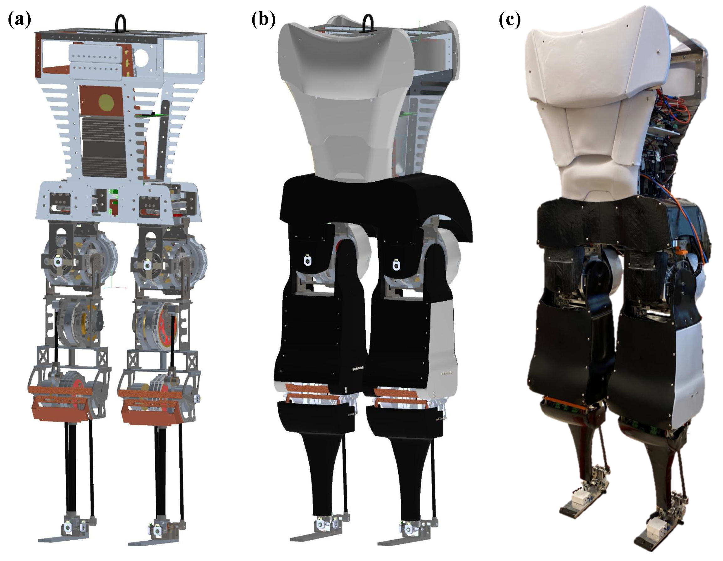
35], the ankle joint actuation setup was designed using a parallel four-bar linkage mechanism with coupled actuation driven by two geared brushless DC (BLDC) motors, each equipped with a single-stage planetary gearbox (Figure 2b,c). 
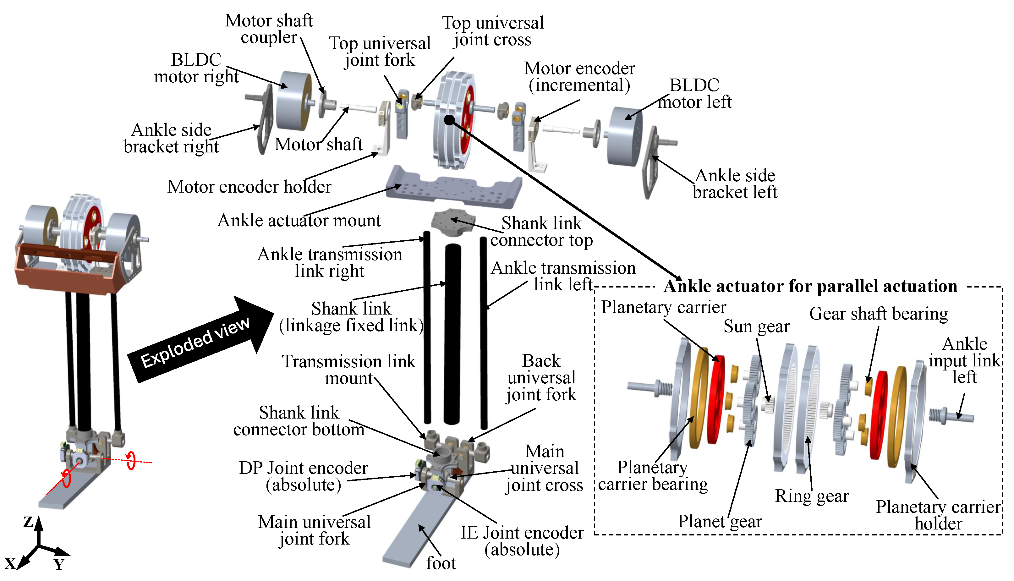
Figure 8 illustrates the design of the ankle actuation system for Mithra.
Each gearbox output connects to the foot through a transmission link and two universal joints, i.e., top and back (see Figure 8), enabling the ankle joint to achieve two degrees of freedom (2-DoF) motion at the main universal joint located on the foot. The dorsi/plantarflexion motions are achieved by rotating both planetary carriers of the ankle gearboxes in the same direction at the same speed. In contrast, inversion/eversion motions are realized by driving the planetary carriers in opposite directions. With this coupled actuation scheme, the ankle joint can deliver twice the torque of a single actuation setup (comprising a motor, gearbox, and single 4-bar linkage) while retaining its output speed. In other words, this configuration allows the ankle to perform high-torque operations at high joint speeds. The ankle actuator differs from the hip and knee actuators, since it employs an outrunner-type BLDC motor paired with a single-stage planetary gearbox. As shown in Figure 8, the ankle motor is mounted on the ankle side bracket, and its motor shaft is attached via a shaft coupler. The shaft passes through a high-resolution incremental encoder for motor position and velocity measurements, and a sun gear is mounted at the end of the shaft.
The exploded view of the ankle actuator in Figure 8 shows the gearbox assembly, which uses a planetary carrier similar in style to the knee gearbox. However, in this case, the ankle input link shaft, which serves as the gearbox output, is mounted at a radial offset from the center of the planetary carrier disk. To ensure smooth and reliable operation under load, a universal joint (the top universal joint) is used at the distal end of the ankle input link shaft. The ankle actuator mount is a rigid component that secures the actuator and encoders, and serves as the structural connection between the shank and the knee joint. The shank connects to the foot through the main universal joint, while the transmission link connects to the foot through the back universal joint, as shown in Figure 8. The ankle’s four-bar parallel linkage mechanism is illustrated in 2D in Figure 9a, along with the optimal link lengths derived from our actuator optimization process.
Integrating parallel mechanisms into the leg posed several design challenges, particularly in maintaining a desired joint range of motion comparable to those of a human’s while achieving compactness. The ankle, having two degrees of freedom, required the inclusion of two gearboxes and motors within a compact space at the knee joint. This led to a wider knee joint in Mithra’s leg. Despite this, the ankle actuators are positioned higher on Mithra’s leg than in most existing robots, so it reduces the distal mass for enhanced leg dynamic movements. In contrast, robots such as ASIMO [4] and COMAN [48] position their ankle actuators below the knee joint. Although the positional difference is only a few centimeters, the associated reduction in distal mass significantly influences the dynamic behavior of the leg.

3.4.2. Kinematic Analysis of the Ankle Actuation Mechanism

The parallel four-bar linkage mechanism of the ankle actuation requires a closed-form inverse kinematics solution for several reasons, including accurate ankle control, force analysis for structural component design, and determining motor positions at robot startup using feedback from joint encoders. In the inverse kinematics calculation of the ankle, two distinct kinematic chains were defined between the two universal joints located at the end of the shank and the ankle input link. One chain passes through the shank link (highlighted in blue in Figure 9b), while the other passes through the ankle transmission link (highlighted in red). These two kinematic chains are further illustrated on a simplified 3D schematic shown in Figure 9c.
The blue kinematic chain begins at the main universal joint located at the end of the shank. From this point, the transformation proceeds as follows: a translation along the z-axis by a distance of L s to the center of the ankle gearbox, followed by a rotation about the gearbox output axis by an angle θ m representing the geared motor angle; next, a translation along the x-axis from the center of the gearbox to the rotational axis indexed by 1 y ; and finally, a translation along the y-axis to reach the universal joint at the end of the ankle input link. The final homogeneous transformation matrix [49] for this kinematic chain is given by
H j b = cos ( θ m ) 0 sin ( θ m ) L i cos ( θ m ) 0 1 0 L 1 sin ( θ m ) 0 cos ( θ m ) L s L i sin ( θ m ) 0 0 0 1
Likewise, the final homogeneous transformation matrix for the red kinematic chain can be obtained by considering rotations at ankle joint (i.e., θ j x , θ j y ), rotations at linkage joints (i.e., θ 1 x , θ 1 y , θ 2 x , θ 2 y ), and translations in all x, y, and z directions:
H j r = H r 1 H r 2 H r 3 H r 4 H r 5 H r 6 H r 7
where H r 1 = 1 0 0 0 0 cos ( θ j x ) sin ( θ j x ) 0 0 sin ( θ j x ) cos ( θ j x ) 0 0 0 0 1 , H r 2 = cos ( θ j y ) 0 sin ( θ j y ) 0 0 1 0 0 sin ( θ j y ) 0 c o s ( θ j y ) 0 0 0 0 1 , H r 3 = 1 0 0 L 4 0 1 0 L 3 0 0 1 L 5 0 0 0 1 ,
H r 4 = 1 0 0 0 0 cos ( θ 2 x ) sin ( θ 2 x ) 0 0 sin ( θ 2 x ) cos ( θ 2 x ) 0 0 0 0 1 , H r 5 = 1 0 0 0 0 1 0 L 2 0 0 1 0 0 0 0 1 , H r 6 = cos ( θ 2 y ) 0 sin ( θ 2 y ) 0 0 1 0 0 sin ( θ 2 y ) 0 c o s ( θ 2 y ) 0 0 0 0 1 ,
H r 5 = 1 0 0 0 0 1 0 0 0 0 1 L c 0 0 0 1 .
Since L c and L 2 are fixed link lengths in the linkage mechanism, the total distance from the top universal joint (at the ankle input link) to the back universal joint (at the heel) can be computed using the Pythagorean theorem, as follows:
V 1 V 2 = L c 2 + L 2 2
where V 1 and V 2 are the position vectors of the center of top and back universal joints, respectively, relative to the ankle joint (Figure 9d). Note that V 1 can be obtained from H j b . A new homogeneous transformation matrix, H j 2 , which is constructed from the matrix product H r 1 H r 2 H r 3 , can be used for computing V 2 . After expanding Equation (3) and simplifying, the following relation can be derived:
sin θ m + a cos θ m = b
where a and b depend only on the (fixed) linkage lengths and the ankle angles, and not on θ m . Solving Equation (4) we obtain
θ m = sin 1 ( b ± a a 2 b 2 1 1 + a 2 )
where plus and minus correspond to the left and right kinematic chains, respectively, in the coupled actuation of parallel linkage mechanism. Using the previously derived relationship for the ankle gearbox output position, θ m , the corresponding output velocity, θ ˙ m , and acceleration, θ ¨ m , can be obtained by considering the first (Jacobian) and second time derivatives of θ m , respectively. Through further analysis of the kinematic chains, the additional joint angles θ 1 x , θ 1 y , θ 2 x , and θ 2 y can also be determined. These intermediate angles are essential for estimating quasi-static forces acting on the linkage components during both walking and running, which are to be used in the engineering analysis of structural components.

3.4.3. Structural Analysis

As with the hip and knee actuation setups, aluminum 7075-T6 was selected for the construction of all major structural components in the ankle actuation system, except for the shank link rod and transmission link rods, which were designed using carbon fiber tubes. Additionally, stainless steel 410 was chosen for the planetary gearbox output shaft due to its higher strength and wear resistance requirements. All structural components were designed to be lightweight while ensuring structural integrity, resistance to deformation, and the prevention of buckling under the maximum forces anticipated during dynamic activities. All designed components of Mithra’s ankle actuation system were further analyzed and optimized using extensive FEA, following the same methodology applied to the hip and knee actuation setups. Figure 10 presents the FEA results of the final design version of the most critical structures, including the ankle side bracket, ankle actuator mount, ankle planetary carrier assembly with output shaft, transmission link assembly, shank link assembly, main universal joint fork, and main universal joint cross.
The FEA on the ankle side brackets was conducted by applying fixtures at the array of clearance holes that is used to fasten the bracket to the ankle actuator mount and applying the calculated forces to the extruded shaft in all three directions. Figure 10a shows the outcomes of this analysis. The results indicate that the final design version of the bracket has a minimum FoS greater than 2, confirming its structural integrity under the maximum loading conditions. The ankle actuator mount is another critical component, as it houses both ankle geared motors. It experiences high stress during foot–ground impacts due to its direct connection to the shank. Further, during the swing phase, the knee actuator force is applied to and transmitted through this mount. The FEA results for the final design version of this component in Figure 10b shows a minimum FoS of 2 at the worst-case conditions, validating its readiness for integration into Mithra. For the ankle planetary carrier, the FEA was performed similar to the analysis conducted for the knee planetary carrier. Considering that the output shaft is fabricated from stainless steel 410 and is positioned near the boundary of the carrier disk, the analysis was conducted on the assembly of the planetary carrier and the ankle input link. As shown in Figure 10c, the final design version demonstrated a minimum FoS of 2.1, which is sufficient for safe operation under maximum load.
Figure 10d presents the FEA results for the ankle transmission link assembly under the maximum loading conditions. The final design achieved a minimum FoS of 2.3. Given the importance of link length to joint position and power transmission, deflection analysis was also performed. The link was found to deflect only 0.0018 mm at maximum load, which is negligible and does not compromise actuator performance. A higher safety factor was required for components closer to the foot due to the increased impacts experienced at the distal end of the leg. To address this, a minimum FoS of 2.5 was targeted for all foot-level structural components. Figure 10e–g present the FEA results for the final design versions of the shank assembly, main universal joint cross, and the joint fork located below the knee, respectively. All components met or exceeded the FoS threshold of 2.5, ensuring structural integrity, resistance to deformation, and protection against buckling under the maximum dynamic loads. During both piecewise and assembly-level FEA, we aimed to replicate real-world conditions as accurately as possible. For example, in the case of the main universal joint, fixtures were defined to simulate proper support at the roller bearing connections, along with directional fixtures to represent the placement of snap rings that fix the component both radially and axially.

3.5. Fatigue Analysis

All the structural components of Mithra have been optimized with respect to weight, size, and structural integrity to enhance both overall performance and appearance. However, to ensure long-term reliability and durability, fatigue analysis had also been performed on critical components that are subjected to repetitive loading. The critical components for fatigue analysis include those that regularly experience high stress under cyclic loading, parts with complex geometries that are more expensive and time-consuming to manufacture, and components that are difficult to replace, especially if replacement involves disassembling press-fit connections or undertaking labor-intensive procedures. Given that walking is the most common locomotion pattern in humans [50] and align with our study of human-inspired robotic locomotion, fatigue analysis was conducted based on the forces derived from quasi-static analysis scaled to Mithra’s total weight. The analysis considered data from fast walking at a speed of 2.0 m/s, which was chosen as the worst-case scenario for fatigue loading due to the relatively high force repetition involved in this locomotion mode.
Although the S–N curve for Al7075-T6 is available in the published literature (e.g., [51,52]), directly applying these experimentally derived values to custom structural designs is often unrealistic. This is primarily due to variations in factors such as surface finish, loading type, stress concentrations, and operating temperature, all of which significantly influence fatigue performance in real-world applications. To address these discrepancies, a method for adjusting the endurance limit by incorporating six modifying factors has been proposed [53]: surface condition, k s u r f ; size, k s i z e ; loading type, k l o a d ; temperature, k t e m p ; reliability factor, k r e l i ; and miscellaneous items, k m s c . These factors are used to find the material’s endurance limit more accurately to reflect the realistic conditions of the customized structural components during operation. The adjusted endurance limit calculation using Marin’s equation is formulated as
S e = k s u r f k s i z e k l o a d k t e m p k r e l i k m s c S e
Based on the guidelines provided in [54], Mithra’s structural components were assumed to be polished, machined parts. Therefore, the surface condition factor was chosen as k s u r f = 0.9. Since the average sizes of components operate at room temperature, the size and temperature factors were both set to k s i z e =1 and k t e m p = 1, respectively. The loading factor was assigned as k l o a d = 0.85, reflecting the axial nature of the loading condition. For the reliability factor, k r e l i = 0.868 was selected, corresponding to a 95% reliability level, as discussed in [54]. This selection considers the high-performance nature of the robotic applications and the expectation that structural components should endure for the full operational lifespan of the robot with no planned replacements. Since no additional effects such as case hardening or residual stresses were considered, the miscellaneous factor was set to k m s c = 1. After incorporating all these factors, an adjusted endurance limit for Al7075-T6 was found with the consideration of maximum fatigue strength found in the literature [51,52].
From the published data for the S–N curve of Al7075-T6 [51,52], it is observed that the high-cycle fatigue domain extends from 10 3 to 10 8 cycles, with the maximum fatigue strength reaching approximately 150 MPa. To construct an adjusted S–N curve suitable for our customized structural components, we considered the ultimate tensile strength of the material as the reference point at the onset of the high-cycle fatigue domain ( 10 3 cycles) and adjusted endurance limit at the 10 8 cycles. The adjusted S–N curve for Al7075-T6, used in our fatigue analysis, is presented in Figure 11. This curve was derived using the following empirical equation provided in [54]:
σ a = σ f ( 2 N ) β
where σ a is the adjusted stress amplitude, σ f is the ultimate tensile strength of the material, β is the fatigue exponent determined using the endurance strength and its corresponding number of cycles, and N is number of cycles to failure. Using the adjusted S–N curve for Al7075-T6, fatigue analysis was performed on critical structural components of Mithra based on the quasi-static force data derived for a fast walking gait. Among those critical components, the results of the fatigue analysis for the hip internal/external rotation joint back mount, knee input link, ankle side bracket, ankle planetary carrier assembly, and main universal joint cross are presented in Figure 12.
Assuming that a fast-walking scenario with each trial lasts for about 20 min and an average gait cycle duration of approximately 0.8 s, the robot completes around 1500 gait cycles per trial. Over a planned operational lifespan of 5000 trials, the total number of the cycles amounts to approximately 7,500,000. Based on fatigue analysis of critical structural components, the minimum fatigue life is observed at the knee input link, with a simulated total cycles of 11,000,000 for fast-walking conditions. Therefore, it is theoretically evident that Mithra can undergo more than 5000 sessions of 20-minute fast-walking tests without experiencing structural failure or any maintenance requirement due to fatigue.

4. Results and Discussion

Mithra was developed with the goal of providing a reliable and accessible humanoid platform for the advancement of control strategies for human-like locomotion. Mithra’s key anthropometric parameters are available in [35]. Each leg is equipped with six active joints, three at the hip, one at the knee, and two at the ankle, and all actuation systems were carefully engineered and constructed to optimize performance for human-like locomotion. This section presents the design validation and performance assessment of Mithra’s actuators in generating human-like dynamic motions and adapting to external environmental disturbances. In our previous work [35], we reported preliminary actuator performance results, including peak joint torque, joint speed, and range of motion, with comparisons to other well-known humanoid robots. In the present paper, we extend those findings by presenting results from both theoretical and experimental evaluations of Mithra’s actuators. These results are intended to demonstrate the effectiveness of Mithra’s actuators in supporting improved control and overall performance.

4.1. Anthropomorphic Design

As previously mentioned, one of the main objectives in the design of Mithra was achieving kinematic and kinetic attributes similar to those of humans. The outcomes of this anthropomorphic design, as detailed in [35], closely match the target human parameters not only in total mass and height, but in segmental attributes such as mass distribution, link lengths, link inertias, and joint range of motion. We also compared these characteristics with some humanoid robots designed with the same goal (including WALK-MAN [39], TALOS [6], and JAXON3-P [55]), and showed that Mithra outperforms them in almost all metrics. Please refer to [35] for details.

4.2. Hip Joint Configuration

The yaw–roll–pitch configuration is the most commonly implemented hip joint arrangement in humanoid robots [39]. In our design process, we investigated several hip joint configurations to identify the most suitable option that aligns with the design considerations and high-level objectives outlined in Section 2. Table 1 presents the inertia values corresponding to different hip configurations evaluated for Mithra, assuming that the leg structure below the hip remains the same in each case.
The yaw–roll–pitch configuration was confirmed to be the most favorable in terms of effective inertia, as anticipated during the design phase. This configuration is also commonly used in humanoid robots such as Hubo, HRP-2, and Valkyrie. It provides minimal effective inertia at the hip pitch and roll joints, indicating that the actuation setup for these joints contributes to a leg design with lower effective inertia compared to alternative configurations. This reduction in inertia enhances hip joint control by enabling more precise movements that would be difficult to achieve with higher-inertia joints. Moreover, the low inertia at the hip is advantageous for fast stepping motions, as it allows for higher hip swing acceleration. This characteristic supports stable locomotion, particularly in dynamic environments. However, adopting a spherical joint-like hip configuration in Mithra introduced some trade-offs. While it ensures human-comparable ranges of motion, it contributes to a bulkier appearance and limits joint motion compared to robots such as WALK-MAN [39], which employs a non-spherical hip joint with a roll–yaw–pitch configuration that enables larger joint ranges.

4.3. Actuator Bandwidth

In general, a real-world physical system behaves like a low-pass filter, attenuating high-frequency inputs. This characteristic is especially relevant for electric actuators in legged robots, where the cutoff frequency of the actuator system is a critical parameter for characterizing joint responsiveness and agility. Since closed-loop position control is typically employed during the swing phase of bipedal locomotion, we conducted closed-loop position control bandwidth experiments on all joint actuators using benchtop test setups. Figure 13a shows the benchtop setups used for actuators of hip internal/external rotation and hip abduction/adduction. To facilitate continuous testing, the mechanical output of the joint actuators was disconnected, eliminating restrictions imposed by mechanical hard stops. The closed-loop bandwidth test was conducted using a proportional-derivative (PD) controller, with the desired velocity set to zero. Sinusoidal position commands with three different amplitudes, 5, 10, and 15 degrees, were applied as the inputs for controllers whose gains were set to 76.4 Nm/rad for the proportional gain ( k p ) and 0.64 Nm/rad/s for the derivative gain ( k d ). Testing began at a low frequency of 0.1 Hz and gradually increased until the experiment was terminated. The stopping criteria were either the motor current exceeding the 100 A limit imposed by the motor controller or excessive vibration in the fixture.
To compare the experimental results with the theoretical ones, bode plots from the transfer function of the system was also included in Figure 13:
G ( s ) = k p J s 2 + ( k d + B ) s + k p
where k p is 76.4 Nm/rad, k d is 0.64 Nm.s/rad, and J and B are the inertia and damping of the chosen actuator with the values of 0.0007958 kg.m2 and 0.001 Nm.s/rad, respectively. Figure 13b depicts the bode plot containing both theoretical and experimental results. The plots of both experimental and theoretical results indicate that the actuator system exhibits the characteristics of a first-order linear system. In all three cases of sinusoidal position commands, the actuator did not reach the cutoff frequency (3 dB below the low-frequency magnitude), as the experiment had to be stopped before reaching this frequency for the aforementioned reasons. This was due to the fact that the dynamic response of the actuators is so fast that its cutoff frequency is above the practical operation range.
To assess the frequency spectrum relevant to human-like motion, we applied a Fast Fourier Transform (FFT) to the time-domain joint angle data of hip and knee flexion during Mithra’s maximum considered speed, i.e., running at 3 m/s. The resulting frequency spectrum for both hip and knee joint motions are shown in Figure 14, highlighting the dominant frequencies that the actuators must be capable of tracking for the accurate reproduction of human-like running behavior.
In the results derived from the FFT analysis, for the hip and knee joint angles, the representative frequency (after which the amplitudes were negligible) was about 2.8 Hz. The amplitude for the knee at this frequency was 10.6 degrees. For the hip angle, since the amplitude at this frequency was rather small, we focused on the previous significant frequency content point, i.e., 1.4 Hz, at which the amplitude is 11.7 degrees. Based on these results and compared with the frequency response results of Figure 13, it is evident that Mithra’s hip and knee actuators can easily follow these amplitudes with frequencies multiple times higher than the FFT frequency contents. As such, both hip and knee actuators are expected to track human-like joint trajectories for running at 3 m/s with minimal error and sufficient responsiveness.

4.4. Joint Backdrivability

All leg joints in Mithra are designed to be backdrivable, offering several advantages, including improved impact mitigation, enhanced compliance to external forces, and increased battery life through power regeneration. Comparable humanoid robots including WALK-MAN [39], TALOS [6], and JAXON3-P [55], due to their use of transmission systems such as harmonic drives or ball-screws, have mostly non-backdrivable joints. In contrast, through detailed optimization and use of planetary gearing, Mithra’s design led to highly backdrivable joints, which is essential for human-like locomotion. In our previous work [35], we provided a comprehensive analysis of Mithra’s joint backdrivability, including the required backdriving torque for each joint and demonstrations of free-swing behavior in the hip and knee joints. In this paper, we extend that work further by quantitatively assessing and comparing the backdrivability of leg joints and demonstrate the backdrivability of the ankle joint.

4.4.1. Knee Joint

We quantified the backdrivability of Mithra’s joints using the impact mitigation factor (IMF) metric proposed in [31]. This provides a meaningful basis for comparing backdrivability across robotic leg systems by directly accounting for electric actuator design. Also, it emphasizes the importance of actuator design in impact mitigation, particularly considering the inertia-dependent effects on backdrivability. The actuator’s reflected inertia is a crucial parameter, as it governs the peak loads experienced by structural components, gearboxes, and transmission systems during impact events. With this consideration, the IMF metric quantifies how effectively the free dynamics of the actuation system reduce impact impulses on the robot’s floating body by comparing it to a worst-case scenario in which a system with all active joints are rigidly locked, thus reflecting the maximum possible inertia. As noted in [31], the IMF is configuration-dependent and a dimensionless quantity that ranges between 0 and 1. An IMF value of 1 indicates perfect inertial backdrivability, where all impact impulses are fully mitigated by the system’s free dynamics. In contrast, an IMF value of 0 corresponds to a fully non-backdrivable system. In this paper, we present IMF values with respect to the knee joint to assess the backdrivability of Mithra’s leg design. This joint was chosen because the IMF values are strongly correlated with the position of the knee joint, which undergoes a wide range of motion and represents the most powerful joint in the leg system. The calculation of IMF requires access to the detailed design of robots, which are in general not available. However, in [31], the IMF for the humanoid HUBO has been calculated and reported, which we use here as a baseline for comparison with Mithra’s IMF. Figure 15 shows the computed IMF as a function of knee angle, along with a comparison to the IMF values of the HUBO robot [37] and a hypothetical version of HUBO equipped with series elastic actuators (SEAs), as reported in [31].
The low IMF values observed at smaller knee angles in both Mithra and HUBO, as shown in Figure 15, are primarily due to reduced backdrivability in the z-direction, which is less dynamically active during locomotion. In comparison to HUBO, Mithra begins with an IMF value ( ε ) of 0 at a knee angle of zero. This may be attributed to the fact that HUBO defines zero knee flexion in a bent reference position, as it allows for knee hyperextension up to 10 degrees [37], whereas Mithra is limited to 0 degrees at its maximum knee extension, corresponding to a fully straightened leg. However, aside from the low-angle region, Mithra demonstrates significantly higher IMF values across the rest of the knee’s range of motion compared to HUBO. This is due to Mithra’s highly backdrivable knee actuator, in contrast to HUBO’s actuator, which uses a harmonic drive that is known for poor backdrivability at high reduction ratios. Figure 15 also illustrates that while SEAs aim to improve backdrivability in otherwise non-backdrivable systems, Mithra achieves high backdrivability even without incorporating elastic elements. This analysis proves that Mithra’s leg structure is indeed well suited to mitigate ground impacts. Its low mechanical impedance and high sensitivity to external forces contribute to improved force and impedance control, enabling stable and adaptive locomotion.

4.4.2. Ankle Joint

Most robots lack human-like ankle capability, both for flexion and inversion/eversion degrees of freedom, due to the difficulty of placing actuators of considerable size and weight near the foot. As discussed in detail in [35], a main contribution of our novel design framework was an ankle actuator that can accommodate human-like running at 3 m/s without increasing the shank mass and inertia beyond the anthropomorphic range. Further, our multi-objective optimization framework results in other desirable characteristics, including joint backdrivability [35]. In particular, the inversion/eversion motion has been designed to be highly backdrivable in order to naturally adapt to rough terrains and obstacles with minimal control. This is inspired by the findings on how humans adopt passive or minimal proprioceptive control for walking on irregular terrains [56]. To test this property, we conducted a simple experiment where the leg was brought down onto an uneven surface, allowing the ankle to respond passively. Figure 16a shows the ankle joint angle measurements and corresponding snapshots of the inversion/eversion motion (rotation around the x-axis) captured during one of the trials. Note that during these experiments, the dorsiflexion/plantarflexion axis of the ankle was actively controlled to remain at zero by applying appropriate gains in a closed-loop position controller specifically only for that joint movement.
It is evident from the experiment that Mithra’s ankle joint utilizes its backdrivability to adapt to uneven surfaces upon ground contact. Since the closed-loop position controller for the ankle’s x-axis (inversion/eversion) was configured with zero gains, the ankle motion remained unchanged in that direction, even when the leg was subsequently lifted. This behavior demonstrates the natural mechanical compliance of the ankle enabled by its backdrivability, which allows the joint to adapt to irregular terrains without active control and its associated complications and delays.
A less extreme case in interaction with irregular terrains occurs when the actuator is operating using low-gain impedance control. In this case, the actuator behaves similarly to a soft spring-damper, which allows it to adapt to the environment with some resistance. To investigate this behavior, a second experiment was conducted in which non-zero gains were applied to the closed-loop position controller for the inversion/eversion axis as well. As shown in Figure 16b, the joint encoder data and corresponding snapshots illustrate that the ankle adapted to the uneven surface when the foot made contact with the ground, and then returned to its commanded joint angle (zero degrees) when the leg was lifted. Together, these two experiments highlight the backdrivability of Mithra’s ankle joint in enabling the foot to conform to uneven terrain and respond compliantly to external disturbances, rather than rigidly resisting them.

5. Conclusions

To our knowledge and as detailed in our previous paper [35], among the state-of-the-art humanoid robots, Mithra’s kinematics and kinetics are closest to those of an average human. Although the optimization framework proposed in our previous work provided results for actuator selection for our robot, several additional steps were necessary to arrive at a design ready for manufacturing. In particular, this paper addresses key questions such as how the actuators should be arranged, which mechanisms are most appropriate, and how the actuator structure can withstand high running forces. We conducted detailed FEA and fatigue analyses to ensure sufficient structural strength and lifespan, all while preserving human-like inertial and backdrivability characteristics. Further, the performance of the actuators were assessed by benchtop experiments to quantify closed-loop control bandwidth, which proved that the actuators’ agility is indeed higher than what is needed for human-like running. This was achieved through the careful design of the actuators’ outputs, and specifically, their low inertia and friction. These design outcomes also resulted in high backdrivability of the actuators, which was tested through human-like adaptation of the ankle joint to irregular terrains. Future works will include testing the robot for anthropomorphic walking and running, and assessing the performance of the actuators during these tasks.

Author Contributions

Conceptualization, S.R., D.T., and C.S.; methodology, S.R., D.T., and C.S.; software, C.S. and D.T.; validation, C.S. and D.T.; formal analysis, C.S. and D.T.; investigation, C.S. and D.T.; resources, S.R.; data curation, C.S.; writing—original draft preparation, C.S., D.T., and S.R.; writing—review and editing, C.S. and S.R.; visualization, C.S.; supervision, S.R.; project administration, S.R.; funding acquisition, S.R. All authors have read and agreed to the published version of the manuscript.

Funding

This research was in part funded by National Science Foundation, grant number 1953908, subawarded through the University of Michigan with subaward number SUBK00012024.

Data Availability Statement

The raw data supporting the conclusions of this article will be made available by the authors on request.

Acknowledgments

The authors express their thanks for the support of Justin Huff and Harsha Karunanayake for their assistance with development of Mithra and conducting the experiments.

Conflicts of Interest

The authors declare no conflicts of interest.

References

  1. Gu, Z.; Li, J.; Shen, W.; Yu, W.; Xie, Z.; McCrory, S.; Cheng, X.; Shamsah, A.; Griffin, R.; Liu, C.K.; et al. Humanoid locomotion and manipulation: Current progress and challenges in control, planning, and learning. arXiv 2025, arXiv:2501.02116. [Google Scholar]
  2. Ito, S.; Nishio, S.; Ino, M.; Morita, R.; Matsushita, K.; Sasaki, M. Design and adaptive balance control of a biped robot with fewer actuators for slope walking. Mechatronics 2018, 49, 56–66. [Google Scholar] [CrossRef]
  3. Ackerman, E. Boston Dynamics’ Latest Vids Show Atlas Going Hands On. IEEE Spectr. Available online: https://spectrum.ieee.org/boston-dynamics-new-atlas (accessed on 4 November 2024).
  4. Shigemi, S.; Goswami, A.; Vadakkepat, P. ASIMO and humanoid robot research at Honda. In Humanoid Robotics: A Reference; Springer: Dordrecht, The Netherlands, 2018; pp. 55–90. [Google Scholar]
  5. Lohmeier, S. Design and Realization of a Humanoid Robot for Fast and Autonomous Bipedal Locomotion. Ph.D. Thesis, Technische Universität München, Munich, Germany, 2010. [Google Scholar]
  6. Stasse, O.; Flayols, T.; Budhiraja, R.; Giraud-Esclasse, K.; Carpentier, J.; Mirabel, J.; Del Prete, A.; Souères, P.; Mansard, N.; Lamiraux, F.; et al. TALOS: A new humanoid research platform targeted for industrial applications. In Proceedings of the 2017 IEEE-RAS 17th International Conference on Humanoid Robotics (Humanoids), Birmingham, UK, 15–17 November 2017; pp. 689–695. [Google Scholar]
  7. Ackerman, E. Agility Robotics Unveils Upgraded Digit Walking Robot. IEEE Spectr. Available online: https://spectrum.ieee.org/agility-robotics-digit-v2-biped-robot (accessed on 14 October 2019).
  8. Semasinghe, C.; Taylor, D.; Rezazadeh, S. A Unified Optimization Framework and New Set of Performance Metrics for Robot Leg Design. In Proceedings of the 2021 IEEE International Conference on Robotics and Automation (ICRA), Xi’an, China, 30 May–5 June 2021; pp. 4919–4925. [Google Scholar]
  9. Wang, L.; Meng, F.; Kang, R.; Sato, R.; Chen, X.; Yu, Z.; Ming, A.; Huang, Q. Design and Implementation of Symmetric Legged Robot for Highly Dynamic Jumping and Impact Mitigation. Sensors 2021, 21, 6885. [Google Scholar] [CrossRef] [PubMed]
  10. Mikolajczyk, T.; Mikołajewska, E.; Al-Shuka, H.F.; Malinowski, T.; Kłodowski, A.; Pimenov, D.Y.; Paczkowski, T.; Hu, F.; Giasin, K.; Mikołajewski, D.; et al. Recent advances in bipedal walking robots: Review of gait, drive, sensors and control systems. Sensors 2022, 22, 4440. [Google Scholar] [CrossRef]
  11. Park, M.H.; Cho, B.K. Design of New Drive Mechanism for Dynamic Movement of Humanoid Robot Legs. In Proceedings of the 2023 IEEE-RAS 22nd International Conference on Humanoid Robots (Humanoids), Austin, TX, USA, 12–14 December 2023; pp. 1–8. [Google Scholar]
  12. Rezazadeh, S.; Hurst, J.W. On the optimal selection of motors and transmissions for electromechanical and robotic systems. In Proceedings of the 2014 IEEE/RSJ International Conference on Intelligent Robots and Systems, Chicago, IL, USA, 14–18 September 2014; pp. 4605–4611. [Google Scholar]
  13. Rezazadeh, S.; Abate, A.; Hatton, R.L.; Hurst, J.W. Robot leg design: A constructive framework. IEEE Access 2018, 6, 54369–54387. [Google Scholar] [CrossRef]
  14. Ackerman, E. The German robotics company unveils its most ambitious bioinspired robot yet. IEEE Spectr. Available online: https://spectrum.ieee.org/festo-newest-robot-is-a-hopping-bionic-kangaroo (accessed on 2 April 2014).
  15. Song, B.; Lee, D.; Park, S.Y.; Baek, Y.S. Design and Performance of Nonlinear Control for an Electro-Hydraulic Actuator Considering a Wearable Robot. Processes 2019, 7, 389. [Google Scholar] [CrossRef]
  16. Yuan, Z. Current status and prospects of actuator in robotics. Appl. Comput. Eng. 2023, 11, 181–191. [Google Scholar] [CrossRef]
  17. Ackerman, E. Hello, Electric Atlas! Boston Dynamics introduces a fully electric humanoid robot that “exceeds human performance”. IEEE Spectr. Available online: https://spectrum.ieee.org/atlas-humanoid-robot (accessed on 17 April 2024).
  18. Pasch, K.A.; Seering, W.P. On the Drive Systems for High-Performance Machines. J. Mech. Transm. Autom. Des. 1984, 106, 102–108. [Google Scholar] [CrossRef]
  19. Pratt, J.; Krupp, B.; Morse, C. Series elastic actuators for high fidelity force control. Ind. Robot. Int. J. 2002, 29, 234–241. [Google Scholar] [CrossRef]
  20. Yu, L.; Zhao, H.; Qin, S.; Jin, G.; Chen, Y. A Compact Variable Stiffness Actuator for Agile Legged Locomotion. IEEE/ASME Trans. Mechatron. 2024, 30, 1131–1142. [Google Scholar] [CrossRef]
  21. Grimmer, M.; Eslamy, M.; Seyfarth, A. Energetic and Peak Power Advantages of Series Elastic Actuators in an Actuated Prosthetic Leg for Walking and Running. Actuators 2014, 3, 1–19. [Google Scholar] [CrossRef]
  22. Hurst, J.; Rizzi, A.; Hobbelen, D. Series elastic actuation: Potential and pitfalls. In Proceedings of the International Conference on Climbing and Walking Robots, Madrid, Spain, 22–24 September 2004. [Google Scholar]
  23. Wang, S.; van Dijk, W.; van der Kooij, H. Spring uses in exoskeleton actuation design. In Proceedings of the 2011 IEEE International Conference on Rehabilitation Robotics, Zurich, Switzerland, 29 June–1 July 2011; pp. 1–6. [Google Scholar]
  24. Beckerle, P.; Verstraten, T.; Mathijssen, G.; Furnemont, R.; Vanderborght, B.; Lefeber, D. Series and Parallel Elastic Actuation: Influence of Operating Positions on Design and Control. IEEE/ASME Trans. Mechatron. 2017, 22, 521–529. [Google Scholar] [CrossRef]
  25. Chatziandreou, E.; Mathews, C.W.; Braun, D.J. Design of a parallel elastic actuator with a continuously-adjustable equilibrium position. arXiv 2022, arXiv:2212.07601. [Google Scholar]
  26. Sariyildiz, E.; Mutlu, R.; Roberts, J.; Kuo, C.H.; Ugurlu, B. Design and Control of a Novel Variable Stiffness Series Elastic Actuator. IEEE/ASME Trans. Mechatron. 2023, 28, 1534–1545. [Google Scholar] [CrossRef]
  27. Mooney, L.; Herr, H. Continuously-variable series-elastic actuator. In Proceedings of the 2013 IEEE 13th International Conference on Rehabilitation Robotics (ICORR), Seattle, WA, USA, 24–26 June 2013; pp. 1–6. [Google Scholar]
  28. Yu, S.; Huang, T.H.; Yang, X.; Jiao, C.; Yang, J.; Chen, Y.; Yi, J.; Su, H. Quasi-Direct Drive Actuation for a Lightweight Hip Exoskeleton With High Backdrivability and High Bandwidth. IEEE/ASME Trans. Mechatron. 2020, 25, 1794–1802. [Google Scholar]
  29. Meng, F.; Huang, Q.; Yu, Z.; Chen, X.; Fan, X.; Zhang, W.; Ming, A. Explosive Electric Actuator and Control for Legged Robots. Engineering 2022, 12, 39–47. [Google Scholar] [CrossRef]
  30. Seok, S.; Wang, A.; Otten, D.; Kim, S. Actuator design for high force proprioceptive control in fast legged locomotion. In Proceedings of the 2012 IEEE/RSJ International Conference on Intelligent Robots and Systems, Vilamoura-Algarve, Portugal, 7–12 October 2012; pp. 1970–1975. [Google Scholar]
  31. Wensing, P.M.; Wang, A.; Seok, S.; Otten, D.; Lang, J.; Kim, S. Proprioceptive Actuator Design in the MIT Cheetah: Impact Mitigation and High-Bandwidth Physical Interaction for Dynamic Legged Robots. IEEE Trans. Robot. 2017, 33, 509–522. [Google Scholar] [CrossRef]
  32. Arm, P.; Zenkl, R.; Barton, P.; Beglinger, L.; Dietsche, A.; Ferrazzini, L.; Hampp, E.; Hinder, J.; Huber, C.; Schaufelberger, D.; et al. SpaceBok: A Dynamic Legged Robot for Space Exploration. In Proceedings of the 2019 International Conference on Robotics and Automation (ICRA), Montreal, QC, Canada, 20–24 May 2019; pp. 6288–6294. [Google Scholar]
  33. Kernbaum, A.S.; Kitchell, M.; Crittenden, M. An ultra-compact infinitely variable transmission for robotics. In Proceedings of the 2017 IEEE International Conference on Robotics and Automation (ICRA), Singapore, 29 May–3 June 2017; pp. 1800–1807. [Google Scholar]
  34. Naclerio, N.D.; Kerst, C.F.; Haggerty, D.A.; Suresh, S.A.; Singh, S.; Ogawa, K.; Miyazaki, S.; Cutkosky, M.R.; Hawkes, E.W. Low-Cost, Continuously Variable, Strain Wave Transmission Using Gecko-Inspired Adhesives. IEEE Robot. Autom. Lett. 2019, 4, 894–901. [Google Scholar] [CrossRef]
  35. Semasinghe, C.; Taylor, D.; Rezazadeh, S. The Design and Manufacturing of Mithra: A Humanoid Robot with Anthropomorphic Attributes and High-Performance Actuators. Robotics 2025, 14, 28. [Google Scholar] [CrossRef]
  36. Winter, D.A. Biomechanics and Motor Control of Human Movement; John Wiley & Sons: Hoboken, NJ, USA, 2009. [Google Scholar]
  37. Park, I.W.; Kim, J.Y.; Lee, J.; Oh, J.H. Mechanical design of the humanoid robot platform, HUBO. Adv. Robot. 2007, 21, 1305–1322. [Google Scholar] [CrossRef]
  38. Ficht, G.; Behnke, S. Bipedal humanoid hardware design: A technology review. Curr. Robot. Rep. 2021, 2, 201–210. [Google Scholar]
  39. Negrello, F.; Garabini, M.; Catalano, M.G.; Kryczka, P.; Choi, W.; Caldwell, D.G.; Bicchi, A.; Tsagarakis, N.G. Walk-man humanoid lower body design optimization for enhanced physical performance. In Proceedings of the 2016 IEEE International Conference on Robotics and Automation (ICRA), Stockholm, Sweden, 16–21 May 2016; pp. 1817–1824. [Google Scholar]
  40. Sim, Y.; RAmos, J. Tello Leg: The Study of Design Principles and Metrics for Dynamic Humanoid Robots. arXiv 2022, arXiv:2203.00644. [Google Scholar] [CrossRef]
  41. Meyer, J.; Petrou, A. The relative merits of three different power transmission systems for precision tracking space mechanisms. In Proceedings of the 7th European Space Mechanisms and Tribology Symposium, Noordwijk, The Netherlands, 1–3 October 1997; Volume 410, p. 265. [Google Scholar]
  42. Liu, J.; Chen, B.; Matsumura, S.; Li, C.; Houjoh, H. Design of a novel cycloid drive with a cycloid-arc gear and analysis of its meshing characteristic. J. Adv. Mech. Des. Syst. Manuf. 2012, 6, 310–322. [Google Scholar] [CrossRef]
  43. Elery, T.; Rezazadeh, S.; Nesler, C.; Gregg, R.D. Design and validation of a powered knee–ankle prosthesis with high-torque, low-impedance actuators. IEEE Trans. Robot. 2020, 36, 1649–1668. [Google Scholar] [CrossRef]
  44. Gupta, V.; Deb, A. Analysis of variable gear system on energy consumption in electric vehicle using simulation tool. Int. J. Simul. Syst. Sci. Technol. 2012, 13, 7–11. [Google Scholar] [CrossRef]
  45. Fukuchi, R.K.; Fukuchi, C.A.; Duarte, M. A public dataset of running biomechanics and the effects of running speed on lower extremity kinematics and kinetics. PeerJ 2017, 5, e3298. [Google Scholar]
  46. Wojtusch, J.; von Stryk, O. HuMoD—A versatile and open database for the investigation, modeling and simulation of human motion dynamics on actuation level. In Proceedings of the 2015 IEEE-RAS 15th International Conference on Humanoid Robots (Humanoids), Seoul, Republic of Korea, 3–5 November 2015; pp. 74–79. [Google Scholar]
  47. Schmid, S.R.; Hamrock, B.J.; Jacobson, B.O. Fundamentals of Machine Elements; CRC Press: Boca Raton, FL, USA, 2013. [Google Scholar]
  48. Tsagarakis, N.G.; Cerda, G.M.; Caldwell, D.G. Compliant Leg Mechanism of Coman. In Humanoid Robotics: A Reference; Springer: Dordrecht, The Netherlands, 2019; pp. 407–434. [Google Scholar]
  49. Spong, M.W.; Hutchinson, S.; Vidyasagar, M. Robot Modeling and Control; John Wiley: Hoboken, NJ, USA, 2020. [Google Scholar]
  50. Cech, D.J.; Martin, S.T. Chapter 13—Locomotion. In Functional Movement Development Across the Life Span, 3rd ed.; Cech, D.J., Martin, S.T., Eds.; W.B. Saunders: Philadelphia, PA, USA, 2012; pp. 288–308. [Google Scholar]
  51. Zalnezhad, E.; Ahmed, D.; Sarhan, A.; Abd Shukor, M.; Asri, B. A Fuzzy Logic Based Model to Predict the Fretting Fatigue Life of Aerospace Al7075-T6 Alloy. J. Appl. Sci. 2012, 1, 39–48. [Google Scholar]
  52. Zapletal, J.; Vechet, S.; Kohout, J.; Liskutin, P. Fatigue Lifetime of 7075 Aluminium Alloy from Ultimate Tensile Strength to Permanent Fatigue Limit. Komunikacie 2009, 11, 17–21. [Google Scholar] [CrossRef]
  53. Courtney, T.H. Mechanical Behavior of Materials; Waveland Press: Long Grove, IL, USA, 2005. [Google Scholar]
  54. Budynas, R.G.; Nisbett, K.J.; Nisbett, J.K.; Shigley, J.E. Shigley’s Mechanical Engineering Design; McGraw-Hill Education: New York, NY, USA, 2015. [Google Scholar]
  55. Kojima, K.; Kojio, Y.; Ishikawa, T.; Sugai, F.; Kakiuchi, Y.; Okada, K.; Inaba, M. A robot design method for weight saving aimed at dynamic motions: Design of humanoid JAXON3-P and realization of jump motions. In Proceedings of the 2019 IEEE-RAS 19th International Conference on Humanoid Robots (Humanoids), Toronto, ON, Canada, 15–17 October 2019; pp. 586–593. [Google Scholar]
  56. Segal, A.D.; Yeates, K.H.; Neptune, R.R.; Klute, G.K. Foot and ankle joint biomechanical adaptations to an unpredictable coronally uneven surface. J. Biomech. Eng. 2018, 140, 031004. [Google Scholar] [CrossRef]
Figure 1. Mithra humanoid robot platform. (a) A 3D CAD model of mechanical structure; (b) a 3D CAD model with covers; and (c) the final manufactured version.
Actuators 14 00243 g001
Figure 2. Mithra’s leg structure. (a) Kinematic structure; (b) schematic of the joint actuation; and (c) a 3D model of the leg design.
Actuators 14 00243 g002
Figure 3. Joint actuation system of Mithra. (a) Standard planetary gearbox; (b) compound planetary gearbox; and (c) actuation system configuration for each joint.
Actuators 14 00243 g003
Figure 4. The design of Mithra’s 3-DoF hip joint.
Actuators 14 00243 g004
Figure 5. FEA results of structural components in the hip actuation system. (a) Hip abduction/adduction joint mount; (b) hip flexion/extension joint mount; (c) hip internal/external rotation joint back mount; (d) hip flexion/extension joint mounting frame; and (e) hip internal/external rotation joint mounting frame.
Actuators 14 00243 g005
Figure 6. The design of Mithra’s knee actuator.
Actuators 14 00243 g006
Figure 7. FEA results of structural components in the knee actuation system. (a) Knee side bracket top; (b) knee side bracket bottom; (c) knee planetary carrier; (d) knee input link; (e) knee connecting column; and (f) knee transmission link assembly.
Actuators 14 00243 g007
Figure 8. The 2-DoF actuation for Mithra’s ankles.
Actuators 14 00243 g008
Figure 9. Kinematic chain of the ankle setup. (a) The 2D four-bar linkage; (b) the kinematic loops shown on the spatial actuation mechanism; (c) the kinematic loops shown schematically; and (d) vectors V 1 and V 2 used for solving the inverse kinematics.
Actuators 14 00243 g009
Figure 10. FEA results of the structural components in the ankle actuation system. (a) Ankle side bracket right; (b) ankle actuator mount; (c) ankle planetary carrier with shaft assembly; (d) ankle transmission link assembly; (e) shank assembly; (f) main universal joint cross; and (g) main universal joint fork.
Actuators 14 00243 g010
Figure 11. Adjusted S-N curve for Al7075-T6 used for fatigue analyses.
Actuators 14 00243 g011
Figure 12. Fatigue analysis results of the structural components. (a) Hip internal/external rotation joint back mount, (b) knee input link, (c) ankle side bracket, (d) ankle planetary carrier assembly, and (e) universal joint cross.
Actuators 14 00243 g012
Figure 13. Actuator bandwidth experiment: (a) benchtop setup for testing the actuators and (b) bode plot results from the test on the hip flexion/extension actuator.
Actuators 14 00243 g013
Figure 14. Frequency spectrum of joint trajectories for hip and knee during a human running scenario at 3 m/s.
Actuators 14 00243 g014
Figure 15. Impact mitigation factor in terms of the knee angle for Mithra in comparison with Hubo (with and without SEAs). The vertical green line corresponds to Mithra’s maximum knee flexion angle.
Actuators 14 00243 g015
Figure 16. Ankle backdrivability tests. (a) Passive response and (b) active control of ankle inversion/eversion with low impedance gains.
Actuators 14 00243 g016
Table 1. Inertia comparison for different hip actuator configurations.
Effective Inertia at
Hip Actuator ConfigurationHip YawHip RollHip Pitch
(kgm2)(kgm2)(kgm2)
Roll–Yaw–Pitch0.093.892.15
Roll–Pitch–Yaw0.063.223.21
Pitch–Roll–Yaw0.063.563.61
Yaw–Roll–Pitch0.162.032.10
Disclaimer/Publisher’s Note: The statements, opinions and data contained in all publications are solely those of the individual author(s) and contributor(s) and not of MDPI and/or the editor(s). MDPI and/or the editor(s) disclaim responsibility for any injury to people or property resulting from any ideas, methods, instructions or products referred to in the content.

