1. Introduction
Manual gait physiotherapy has traditionally been the primary form of rehabilitation for individuals recovering from neurological injuries such as stroke, traumatic brain injury, and spinal cord injury [
1,
2,
3]. In recent years, however, rehabilitation robots have been increasingly integrated into treatment programs to assist with repetitive movement training and partially take on the burden of weight-bearing, thus reducing the physical demands on physiotherapists [
4,
5,
6,
7,
8].
Experience gained from the use of rehabilitation robots has led to key insights about optimizing robot-assisted rehabilitation to improve patient outcomes. One of the most widely adopted principles is the concept of the “assist-as-needed” approach [
7,
9,
10,
11]. This approach ensures that the robot provides assistance only when necessary, without diminishing the patient’s voluntary efforts. When the patient’s own movement is sufficient, the robot simply follows their lead, ideally with minimal interaction forces and torques—a characteristic referred to as the high robot’s transparency [
12,
13,
14,
15]. This strategy aligns with the nature of movement impairments, where patients often retain some level of mobility and may require support only in specific ranges of motion. By complementing, rather than replacing, the patient’s voluntary input, assist-as-needed therapy promotes active participation and encourages the restoration of independent movement [
16].
Among the various configurations of rehabilitation robots, cable-driven systems have gained attention as a promising approach [
17,
18,
19], addressing several limitations inherent to rigid-link robots [
5,
20,
21]. Notably, rigid-link designs often introduce weight and inertia that can increase metabolic costs, affect natural movement, particularly when applied to distal, high-acceleration body segments [
22,
23,
24,
25]. Such challenges necessitate the use of complex control strategies, including predictive components, to compensate for these dynamic effects.
Cable-driven rehabilitation robots offer a compelling alternative by relocating motors away from fast-moving joints, such as the knees and ankles, where their mass would have the most pronounced dynamic impact [
22]. Instead, these systems position the motors closer to the body’s center of mass (e.g., the upper body), where the lower accelerations make the dynamic effects of motor mass more manageable. In this design, forces are transmitted to the body segments via cables or Bowden cables, enabling innovative applications such as overground exoskeletons [
17,
18] and myosuits [
26].
Furthermore, an alternative configuration involves completely decoupling the motors from the user’s body. By positioning the motors at fixed external points, such as a stationary frame near a treadmill, their mass and associated inertia are entirely removed from the user, thus increasing their transparency. This setup presents a novel pathway for reducing the mechanical burden on the user and enhancing transparent user experience while improving the system’s effectiveness.
Cable-driven rehabilitation robots face significant challenges due to their reliance on tensile forces. Controlling a robot with n degrees of freedom requires at least n + 1 actuated cables, leading to an over-constrained system [
27,
28]. A key challenge for such systems lies in the precise control of cable tension forces, which directly impacts the interaction forces between the user and the robot. Effective control must prioritize high transparency in user interaction. This entails maintaining negligible tension forces when no assistance is needed while ensuring cables remain just above the threshold of slackness. Achieving this is particularly challenging due to the inherent redundancy of cable-driven systems.
Cable tension control typically involves winding and unwinding cables on motor axes using appropriate current or speed control. This process often relies on various measurement systems, including force sensors to monitor cable forces, kinematic sensors to track body segment or cable attachment positions [
17,
29], and elastic elements to absorb and dissipate undesired forces [
30]. Achieving proper cable tension requires integrating these sensory inputs into sophisticated control strategies, such as impedance [
17,
28] or admittance control [
31], optimization techniques like linear and quadratic programming [
32,
33], or closed-form and geometric techniques [
34,
35]. However, these methods necessitate real-time implementation with high computational demands. High-resolution sensors, minimal delays in control signals, and low control loop times are critical to reducing latencies and improving responsiveness, thereby enhancing transparency.
The quality of haptic interaction is also influenced by the dynamic response characteristics of the motor controller and motors used in low-level control. While conventional servomotors are commonly employed in cable-driven rehabilitation robots, high-density torque motors are sometimes preferred due to their superior dynamic response to kinematic and torque/force errors, which reduces latency. However, these motors are heavier, posing challenges for rehabilitation robotics, especially in wearable devices like exoskeletons. Alternatively, lighter low-torque motors combined with high-reduction gears [
36] can increase actuator torque but at the cost of reduced velocity, diminished back-drivability, increased friction, and higher perceived inertia—all of which negatively affect transparency.
One of the key principles tested in attempts to achieve highly transparent interaction in wearable devices is mimicking anisometric contractions of human muscles, which encompass both concentric (muscle shortening) and eccentric (muscle lengthening under load) phases [
37]. Various approaches have been explored to replicate these contractions effectively. Powered cable-driven devices, utilizing brushless DC motors driving pulleys, assist during both phases [
38,
39]. However, these systems often consume unnecessary electrical power, particularly during eccentric contractions. Some designs address this challenge by employing techniques like cable slack management [
40] or zero-torque control [
41], but issues such as cable derailment or limited system bandwidth remain problematic. Alternatively, passive systems using spring-clutch mechanisms [
36,
42] or electromechanical/electromagnetic clutches [
43,
44] offer more efficient and transparent assistance by decoupling the motor from the joint. These systems, however, come with trade-offs, including the need for an additional power source for clutch control, which may increase the system’s size, inertia, and control complexity.
This paper presents a novel actuation approach, the PACE-R module, designed to apply force impulses to human body segments in a transparent manner. The proposed lightweight system is a cable-driven, remotely actuated mechanism featuring a key innovation: The cable attached to the target body segment is in general not wound around or fixed to the motor or the pulley mounted on it. Instead, it passes through a gap in a pulley-like component mounted on the motor and connects on the opposite side to a nearly constant-force spring, which in this configuration passively maintains low cable tension. This design allows the cable to remain decoupled from the motor when no assistance is required, with the tension spring ensuring a consistent, minimal tension during movement. When movement assistance is needed—as determined by the operator—the motor rotates to clamp the cable, ensuring mechanical coupling between the two, and pulls the connected body segment toward the module to provide the desired assistive force. Such design enables a simple, open-loop, on–off control strategy that switches only between assistive and non-assistive phases, eliminating the need for complex, continuous cable force or tension control as required in closed-loop systems. As a result, it bypasses the negative effects of motor inertia, mechanical friction, and latency associated with traditional impedance- or admittance-controlled systems. Consequently, the transparency of the PACE-R module is governed solely by the low stiffness of the tension spring, offering a highly responsive and natural interaction for the user. The performance of this mechanism was evaluated through benchtop experiments and real-world applications using an ankle orthosis designed for push-off assistance.
2. Materials and Methods
2.1. PACE-R Module
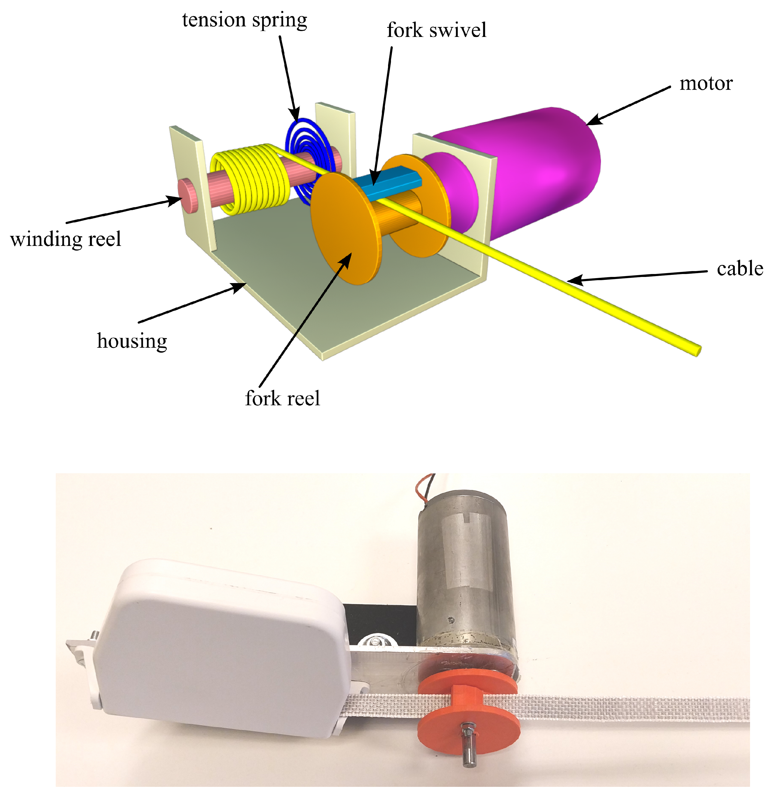
Figure 1 illustrates the schematic design of a PACE-R (Passive Active CablE Robot) module and the actual module. The fork element is composed of a fork reel and a fork swivel, both made of plastic. The fork reel is a cylindrically shaped component with guiding edges and an approximate core radius of 15 mm. It is centrally mounted on the shaft of a DC motor (Dunkermotoren GmbH, Bonndorf im Schwarzwald, Germany). Positioned approximately 20 mm away and parallel to the motor axis is a secondary axis, embedded between the guiding edges of the fork reel and passing through the fork swivel. This allows the fork swivel to rotate passively relative to the fork reel within the limited range, constrained by either edge of the swivel hitting the cable. The design of the fork element resulted in a circumference of approximately 115 mm. The mechanism also features a fabric-based cable and a reel-type tension spring housed within a casing that includes a lightweight winding reel. Reel springs are known for providing almost constant force, even when extended to many times their coiled length. For the PACE-R module, a reel spring was selected with a tension force not exceeding 10 N.
The tension spring is anchored at one end to the housing, with its other end connected to the winding reel, where it applies a light winding torque. This torque generates a gentle pulling force at the cable’s proximal end. The proximal end of the cable is coiled around the winding reel, while the distal end extends through the gap in the fork, defined by the fork reel and fork swivel, and attaches to a designated attachment point.
2.2. Modes of Operation
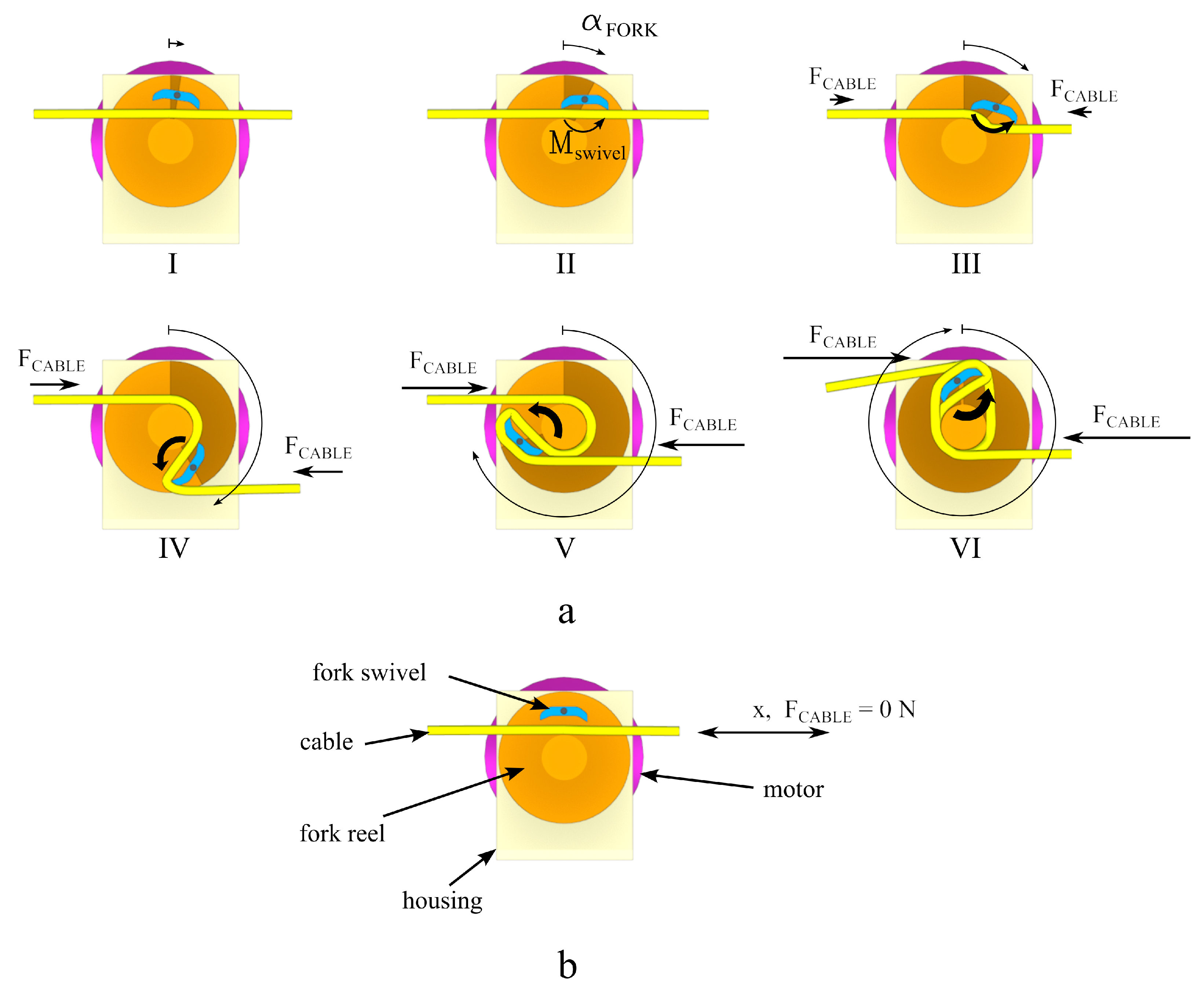
The PACE-R module operates in two distinct modes, depending on whether force is applied to the attachment point at the distal end of the cable or not (
Figure 2):
Active mode (denoted as MACTIVE)—In this mode, the motor is actuated and coupled to the cable, applying force to the cable’s attachment point at its distal end.
Passive mode (denoted as MPASSIVE)—In this mode, the motor is not actuated and is decoupled from the cable, resulting in no force being applied to the cable’s attachment point at the distal end. Instead, the PACE-R module allows the cable to passively follow the movement of its distal attachment point while maintaining minimal tension to prevent its slackness.
During M
ACTIVE (
Figure 2a), the motor first rotates (phase I), causing the fork reel to turn in the same direction. Initially, due to the gap in the fork that is wider than the cable, this rotation at first does not generate any pulling force F
CABLE in the cable. As the one side of the light fork swivel makes contact with the cable (phase II), the cable tension causes the swivel to rotate momentarily along its axis in the opposite direction as indicated by M
swivel. Continued rotation of the fork reel eventually brings both ends of the fork swivel into contact with the cable, blocking the fork swivel in place (phase III). This locking point, referred to as the minimal angle of action of the fork reel, is denoted as
min. When the fork reel rotates past
min (phase IV), the torque on the swivel M
swivel gradually increases (indicated by larger thickness of the M
swivel) which gradually increases pressure of one end of the swivel against the cable, effectively clamping it firmly against the fork reel and winding it around the fork. This action generates a pulling force, F
CABLE, which draws the attachment point and the distal end of the cable toward the PACE-R module. As the fork continues to rotate (phases V and VI), the length of the cable wound onto the fork increases, resulting in a progressively larger pulling force, F
CABLE, at the attachment point (
Figure 2a). At the same time, this F
CABLE also acts on the proximal end of the cable, causing it to unwind from the winding reel.
M
PASSIVE begins once the actuation of the motor is suspended, rendering it passive, and the PACE-R module no longer generates a pulling force F
CABLE on the cable’s distal end. In M
PASSIVE, a tension spring applies a small torque to the winding reel, which when combined with a potential pulling force generated by the movement of the body segment, causes the fork, motor, and cable to unwind. Once the fork reel returns to
min, the fork swivel no longer presses against the cable, allowing it again to slide freely through the fork’s gap. Due to
min, along with the fork’s inertial characteristics, the motor, and the cable tension from the preceding M
ACTIVE, the fork may return to an angle within the range of
-min <
return <
min. Here,
-min defines the angle past the vertical in the opposite direction to which the fork must rotate before both ends of the fork swivel again contact the cable. Together,
-min and
min determine a “dead zone” for the fork, where PACE-R module cannot exert force on the cable’s distal end. Within this range, the cable decouples from the fork and the motor, making it mechanically independent (
Figure 2b).
During MPASSIVE, if the attachment point at the cable’s distal end moves closer to the PACE-R module, the tension spring maintains adequate tension by applying a small torque to the winding reel, winding up any excess cable to prevent its slackness. Conversely, if the attachment point moves away, it overcomes the torque from the tension spring, causing the cable to unwind from the winding reel as needed. The low stiffness of the tension spring and the mechanical decoupling of the cable from the motor minimize the perceived mass and inertia of the PACE-R module, making it highly transparent to the user. This ensures that the PACE-R module does not hinder the movement of the attachment point during MPASSIVE.
2.3. Control
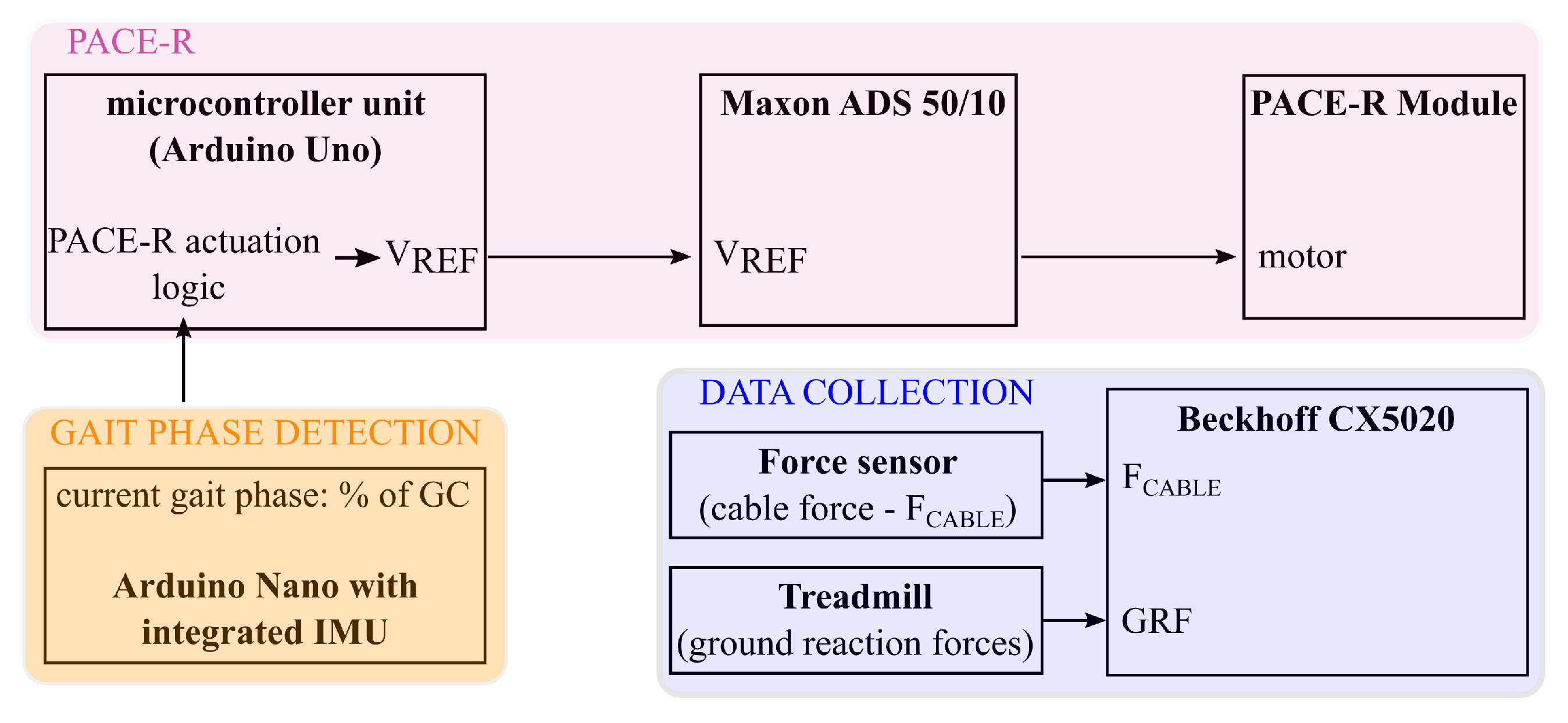
The control logic of the PACE-R module is implemented using an Arduino Uno micro-controller circuit and operates in two control modes, corresponding to the two modes of operation MPASSIVE and MACTIVE, respectively.
In MACTIVE, the PACE-R actuation logic generates a reference voltage signal, VREF (0–10 V), which is sent to the motor controller (Maxon ADS 50/10, Maxon Group, Sachseln, Switzerland). VREF is a pulse signal with adjustable amplitude and duration. The motor controller is set to current control mode, making the amplitude of VREF proportional to the desired current supplied to the motor—effectively setting the reference torque at the motor axis. The control scheme in MACTIVE implements an open-loop control and does not implement any regulation relationship between the VREF and FCABLE, resulting in an unregulated FCABLE. Instead, the amplitude and duration of the VREF are adjusted by the operator to achieve the desired movement effect and remain constant unless modified.
In MPASSIVE mode, no motor actuation is required. The VREF is therefore set to zero, meaning the motor controller supplies no current to the PACE-R motor. This renders the motor passive, allowing its rotation to be influenced solely by external force. Consequently, the cable can fully unwind from the fork at the beginning of MPASSIVE, allowing the fork to return to a position within the range -min < return < min, where the cable can slide freely through the gap in the fork.
2.4. Benchtop Experiment
2.4.1. Experiment Setup
To characterize the dynamic characteristics of the PACE-R module, a benchtop experiment was designed using the module under controlled conditions (
Figure 3). The cable of the PACE-R module was attached directly to the force sensor (U9C 0.5 kN, HBK, Darmstadt, Germany). Due to the compliant tension spring, the cable was inherently tensioned. Since the attachment point of the cable was fixed and therefore immobile, the pulling force, F
CABLE, was propagated almost instantaneously from the cable to the force sensor. This experimental configuration simulates a scenario where the PACE-R module is attached to an object with infinite mass, imposing extremely high mechanical demands on the system. Such conditions are unlikely in rehabilitation settings, where forces are typically applied to body segments with finite mass.
2.4.2. Experimental Conditions
Each benchtop experiment was conducted under nine experimental conditions, combining one of three force amplitudes (determined by the V
REF: 3.3 V, 6.6 V, and 10 V) with one of three durations of M
ACTIVE (T
ACTIVE: 250 ms, 500 ms, and 750 ms). For each experimental condition, the angle of rotation of the fork was initially set to the neutral (vertical) position. The experiment then included 15 repetitions of M
ACTIVE, with the first five serving as test repetitions, which were excluded from the analysis. During these initial test repetitions, the
return (see
Section 2.2) was allowed to stabilize at a stationary value. This value was then used as the initial angle of rotation of the fork for the remaining 10 repetitions.
2.4.3. Data Collection and Data Analysis
The tension force in the cable, FCABLE, was measured using a force sensor (U9C 0.5 kN, HBK, Darmstadt, Germany), with the force sensor signal amplified by an analog amplifier (GSV-1A4 DSub37/2, ME-Meßsysteme GmbH, Hennigsdorf, Germany). A rotary absolute magnetic encoder (RM44, RLS, d.o.o, Komenda, Slovenia) was also employed to record the rotation angle of the fork. All signals, including the VREF signal, were recorded using an embedded computer (Beckhoff CX5020, Beckhoff, Verl, Germany).
The recorded signals were segmented into time windows spanning from 250 ms before to 1250 ms after the onset of MACTIVE, (defined as VREF > 0). These segments were then averaged across ten repetitions.
A critical design feature of the PACE-R module that significantly influences the force and fork’s rotation angle profiles is the configuration of the fork reel and fork swivel, which together constitute the fork element. As described in
Section 2.2, the geometry of the fork reel and fork swivel defines a minimal angle of action,
min, which the fork reel must rotate before the cable is coupled with the motor to generate any cable force F
CABLE at its distal end. As a result, there is typically a delay time, t
delay, after the onset of the M
ACTIVE mode of operation before any F
CABLE can be generated at the attachment point.
Similarly, when switching from MACTIVE to MPASSIVE, a time interval, treturn, is required for the tension spring to fully unwind the cable from the fork. During this interval, the rotation angle of the fork gradually returns within the range -min < return < min. Notably, the return angle, return, does not typically align with the neutral position. Both return and treturn are influenced by factors such as the stiffness of the tension spring, the cable force (FCABLE), and angle of rotation of the fork during the preceding MACTIVE mode.
In addition, the dynamic characteristics of the PACE-R module are inherently influenced by the properties of its components. Specifically, these include the limited stiffness of the cable, the low stiffness, friction, and inertia from the tension spring, and the winding reel. These factors collectively result in an underdamped response, characterized by the following parameters:
where tp is the time of the first peak in the FCABLE response, adjusted for tdelay and OS is the overshoot ratio, defined as the amount by which the first peak of the FCABLE response surpasses its steady state level relative to its steady state.
Data analysis was conducted as follows:
The average min, return, treturn, and tdelay, along with their corresponding standard deviations, were calculated across ten repetitions for each experimental condition.
The average K,
and
, along with their corresponding standard deviations, were calculated across ten repetitions according to Equations (
1)–(
3) only for the experimental conditions where T
ACTIVE = 750 ms. It was assumed that T
ACTIVE does not affect K,
and
.
2.5. Real World Demonstration—Push-Off Assistance
2.5.1. Participant
The push-off assistance experiment was conducted as a case study. A neurologically and orthopedically healthy participant was recruited for the study. The participant received information about the experiment and provided written consent to participate. This study was approved by the Institutional Commission for Professional, Medical, and Ethical Issues.
2.5.2. Experiment Setup—Ankle Orthosis
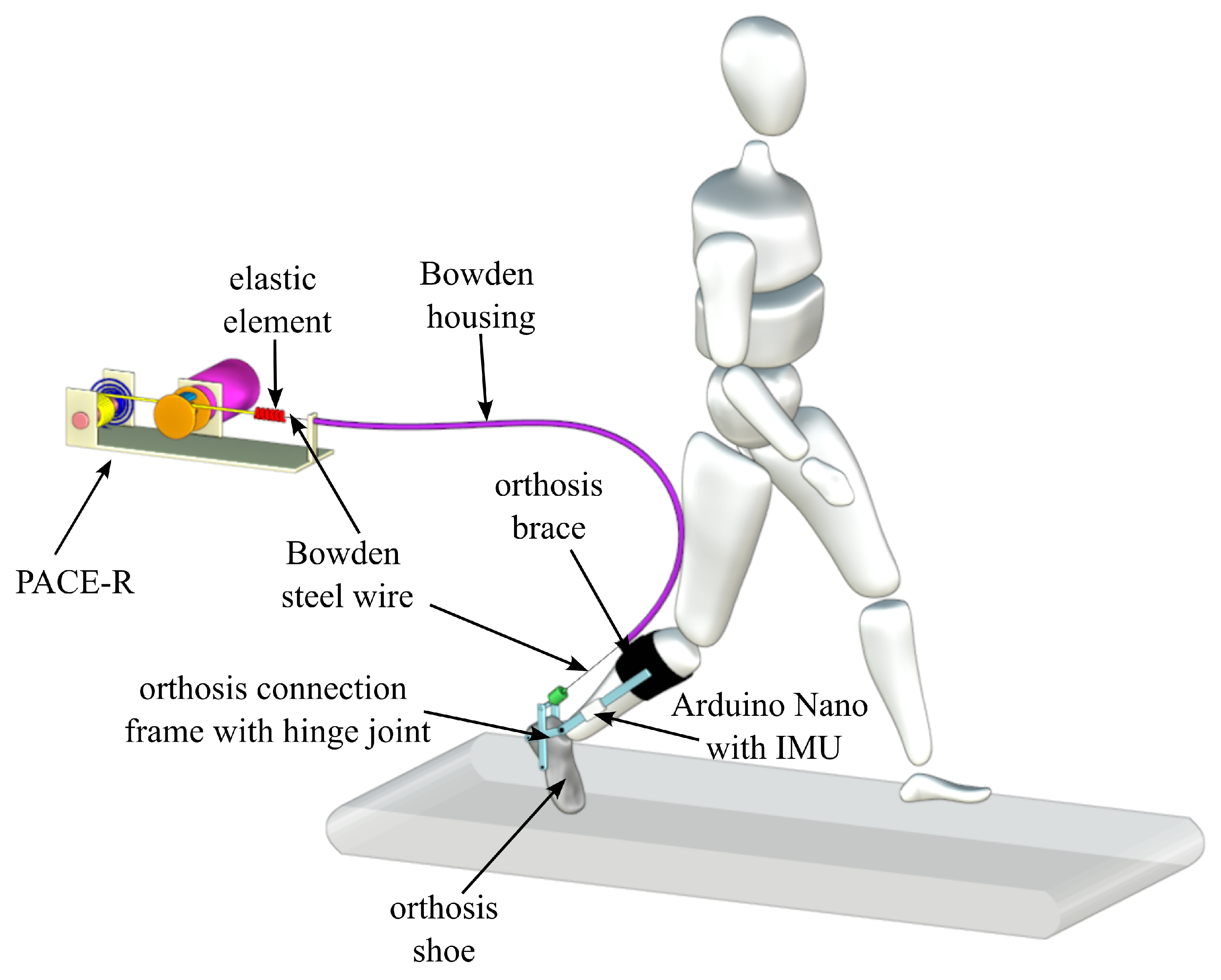
In the real-world demonstration, the PACE-R module was used to assist push-off in the ankle joint, as shown in
Figure 4. The experiment took place on a dual treadmill, with the PACE-R module securely mounted on a fixed frame located behind the participant.
The cable of the PACE-R module was connected to a Bowden steel wire through an elastic element, to attenuate the force impulse transition from the PACE-R module to the attachment point—unlike the near-instantaneous transition observed in the benchtop experiment. This resulted in a more comfortable user experience. Additional criteria included that the elastic element should function as an elastic tendon and possess a stiffness significantly greater than that of the tension spring. The optimal elastic element, with a stiffness of approximately 2050 N/m, was selected based on preliminary tests in which participants qualitatively evaluated comfort using elements of varying stiffness. Tests included randomized force amplitudes and durations, and the element rated most comfortable was chosen.
The Bowden steel wire was enclosed within a Bowden housing that was anchored to the frame near the PACE-R module. The Bowden cable extended from the PACE-R module to the ankle orthosis, where its distal end was attached to the orthosis brace on the shank, just below the knee.
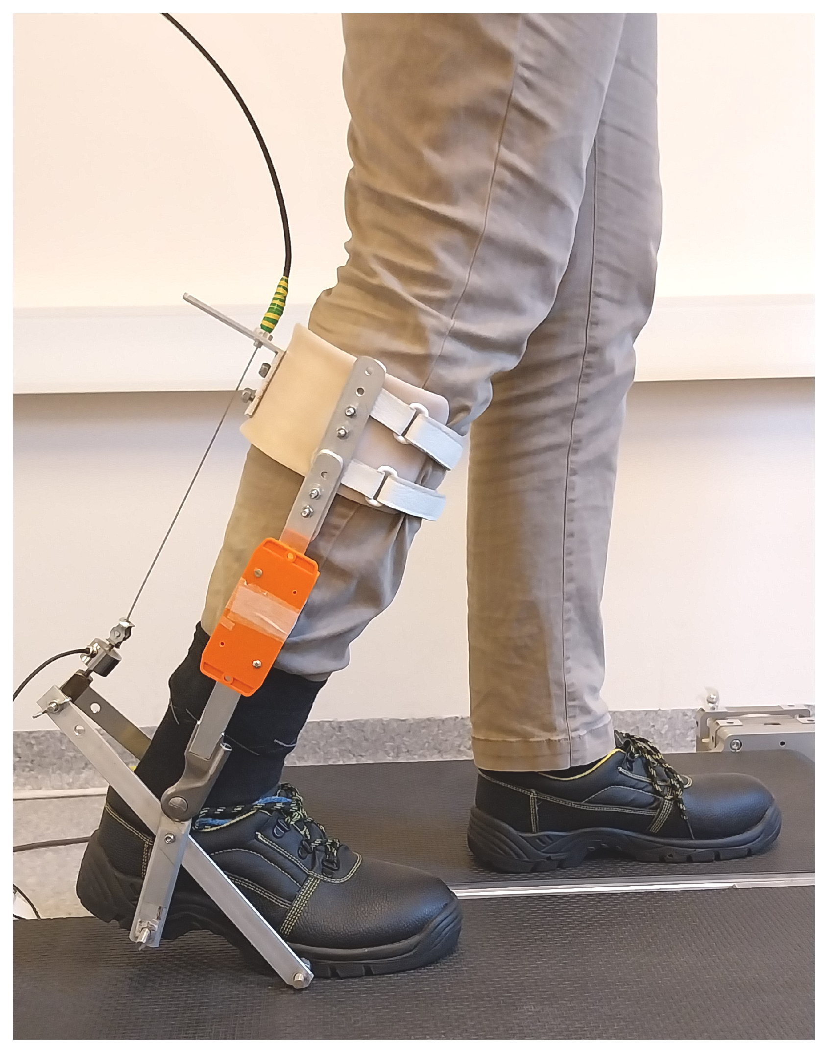
The orthosis brace was connected to a standard shoe through a metal linkage with hinge joints positioned on both the medial and lateral sides of the anatomical ankle joint (
Figure 5). Together, these hinge joints formed an axis of rotation approximately aligned with the anatomical rotation axis of the ankle joint. The distal segment of the hinge joint was secured to the shoe using two bolts tightly fitted and fastened through the rubber sole of the shoe. This provided the necessary structural rigidity and ensured negligible relative movement between the shoe, the metal linkage, and the shank brace. This setup allowed the orthosis brace to rotate freely in both the dorsal and plantar directions, mirroring the movement of the ankle joint.
At the orthosis end, the Bowden steel wire passed through the Bowden housing and attached to a force sensor (U9C 0.5 kN, HBK, Germany) on the heel side of the orthosis shoe. As the ankle joint moved through its full range of movement, the position of the wire with respect to the ankle joint varied slightly. To take a conservative approach in our analysis, the shortest distance was used as the lever arm, set to r
wire = 10 cm (
Figure 4).
Through this configuration, the PACE-R module was able to supplement the user’s voluntary biological ankle moment during MACTIVE by generating additional plantar flexion torque, mimicking the action of the soleus muscle.
2.5.3. Push-Off Assistance
The push-off mechanism at the ankle joint during human walking is characterized by a substantial burst of power generation occurring in late stance. This phase begins at approximately 40% of the gait cycle, peaks around 50%, and concludes just before foot lift-off, at approximately 60% of the gait cycle. To enable effective push-off assistance from the PACE-R module at the ankle joint, it must deliver a similar power burst in the plantar direction, synchronized precisely with the biological push-off. Outside this push-off phase, the cable of the PACE-R module should follow the attachment point’s movement—where the Bowden steel wire connects to the force sensor—with minimal, ideally zero, resistance.
Achieving this behavior requires the PACE-R actuation logic to receive an appropriate signal for detecting the onset of the push-off phase during walking (
Figure 6). Developing a gait event detection algorithm was not within the scope of this study, as numerous methods for identifying gait events such as foot strike, heel-off, and foot-off are well documented in the literature [
45]. Instead, we employed an Arduino Nano 33 BLE microcontroller with an on-board IMU to implement adaptive frequency oscillators, enabling real-time extraction of the gait phase signal (%
GC) [
46].
The extracted %
GC was input to the PACE-R actuation logic (
Figure 6), where it was compared against a predefined %
PUSH-OFF threshold, indicating the expected timing of push-off. When %
GC surpassed the %
PUSH-OFF threshold, the PACE-R module entered the M
ACTIVE mode, with the reference voltage (V
REF) set to a target value greater than 0 V for a designated duration (T
ACTIVE). The %
PUSH-OFF and T
ACTIVE values were determined experimentally, set to 40% of the GC and approximately 350 ms, respectively. Outside this interval, the PACE-R module was operating in M
PASSIVE mode (V
REF = 0 V).
2.5.4. Experimental Conditions
The push-off assistance experiment was conducted on a dual treadmill at a walking speed of 0.5 m/s, which approximates the average walking speed of stroke patients at discharge, as reported in the literature [
47].
The experiment consisted of three trials. In all trials, the participant wore the ankle orthosis connected to the PACE-R module via a Bowden cable as shown in
Figure 5. In the first trial (NoAssist), the PACE-R module remained passive (V
REF = 0 V) throughout the gait cycle, providing no assistance to the biological push-off. In the second and third trials, push-off assistance was provided at two levels, corresponding to V
REF values of 5 V (LowAssist trial) and 10 V (HighAssist trial), respectively.
Each trial lasted approximately two minutes, with a resting period of approximately two minutes between trials.
2.5.5. Data Collection and Data Analysis
The experiment was conducted using a custom-built dual treadmill, where one treadmill was equipped with force sensors to enable measurement of ground reaction forces (GRF) in three planes of movement and center of pressure (CoP) for one side of the body. Reflective markers were placed on predefined anatomical landmarks of the participant’s lower body following the Plug-In-Gait model, and an OptiTrack motion capture system (NaturalPoint, Inc., Corvallis, OR, USA) was used to record three-dimensional marker positions. Lower-body joint angles were calculated using the Plug-In-Gait model, and these data were then combined with CoP and GRF measurements to calculate joint moments and powers for the right lower limb.
The measured ankle plantar flexion moment and power represented both the user’s biological input as well as the contribution from the PACE-R module:
To distinguish these two contributions, the cable force (F
CABLE) generated by the PACE-R module was recorded at the point where it attaches to a force sensor (U9C 0.5 kN, HBK, Germany) (see
Figure 5). Both GRF and F
CABLE signals were recorded with an embedded computer (Beckhoff CX5020, Beckhoff, Germany).
The contributions of the PACE-R module, M
PACE-R and P
PACE-R, to the total ankle plantar flexion moment and power (M
TOTAL and P
TOTAL) were calculated as follows:
where
ankle is the angular velocity of the ankle joint.
This contribution was then subtracted from the total measured joint moment to isolate the biological moment generated by the user:
All data—including joint angles, moments, powers, and the individual contributions from the biological and PACE-R sources to the total ankle moment and power—were segmented into strides. Left and right strides were defined as the intervals between two consecutive foot strikes of the left and right feet, respectively, and results were averaged across strides.
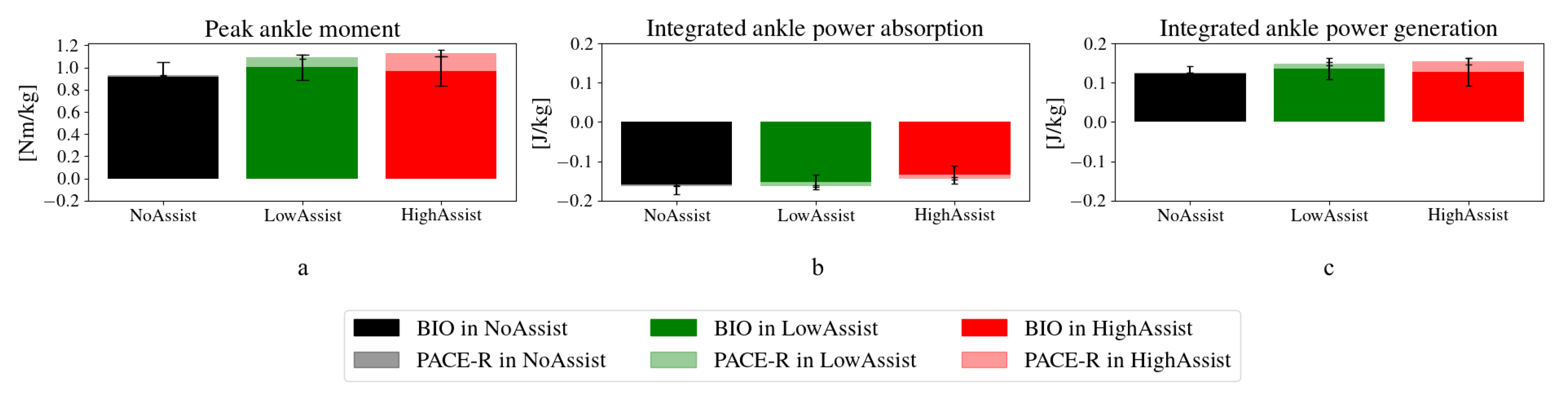
Finally, for all experimental conditions, both contributions to the peak ankle moment were quantified. Additionally, the power was integrated separately over periods of power absorption and power generation to calculate the energy absorbed and generated. The contributions to each of these energy components were also identified for all experimental conditions.
2.5.6. Analysis of Transparency
The transparency of a cable-driven mechanism in rehabilitation refers to its ability to allow the body segments it is attached to move freely with minimal resistance during periods when mechanical intervention is not needed. In this study, the transparency of the experimental setup, consisting of the orthosis and the PACE-R module, was assessed across all three experimental conditions: NoAssist, LowAssist, and HighAssist. This evaluation focused on the contributions of the PACE-R module, MPACE-R and PPACE-R, respectively, to the total ankle moment and power, MTOTAL and PTOTAL, respectively, during periods outside of push-off assistance. These periods correspond to intervals when the PACE-R module operated in passive mode (MPASSIVE). Within each stride, the peak MPACE-R and PPACE-R values during those intervals were averaged across the three trial conditions to quantify the transparency of the experimental setup. The analysis also focused on comparing the cable force during periods with and without push-off assistance.
3. Results
3.1. Benchtop Experiment
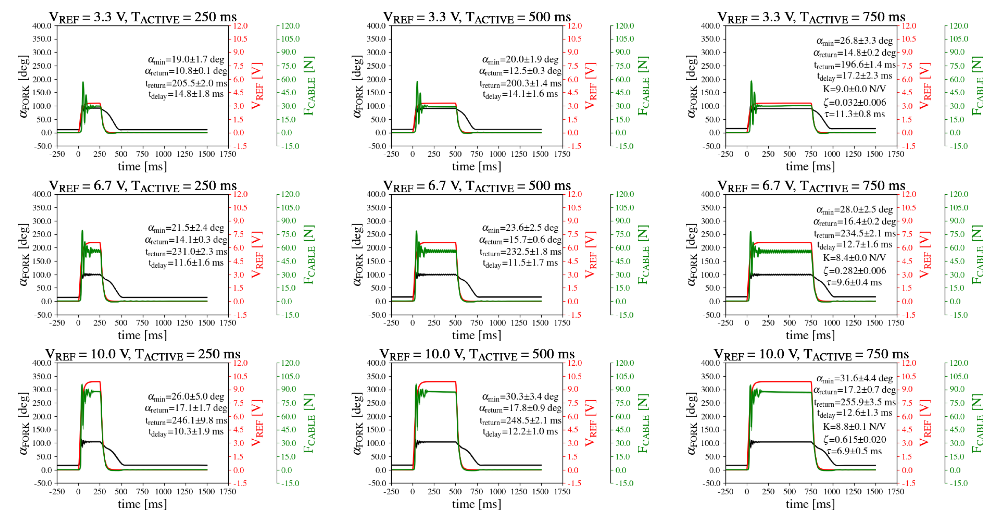
Figure 7 presents average V
REF, F
CABLE,
FORK, and selected descriptive statistics along with their corresponding standard deviations across nine experimental conditions from the benchtop experiment.
Under all experimental conditions, the FCABLE profile revealed characteristics of an underdamped system. This behavior was marked by relatively large, short-term oscillations occurring shortly after the onset of the actuation VREF, before eventually stabilizing at the steady-state level. A delay in the onset of FCABLE relative to VREF was observed, with delays (tdelay) ranging from 10.5 ms to 17.2 ms. Following the initial delay, FCABLE exponentially approached its steady-state value with a time constant () between 6.9 ms and 14.8 ms. The damping factor () was calculated to be between 0.032 and 0.615.
The results further demonstrate that after the transient period, FCABLE stabilized at approximately 28 N, 59 N, and 90 N for VREF values of 3.3 V, 6.7 V, and 10 V, respectively. This relationship was nearly linear, with gain ratio (K) ranging from 8.4 N/V to 9 N/V. Upon switching from the active mode (MACTIVE) to the passive mode (MPASSIVE), FCABLE promptly followed the VREF profile, terminating the pulling action at the attachment point.
The rotation profile of the fork, denoted as FORK, shows its onset time synchronized with the reference voltage (VREF). At t = tdelay, we recorded FORK = min ranging from 19.0 deg (VREF = 3.3 V, TACTIVE = 250 ms) to 31.6 deg (VREF = 10 V, TACTIVE = 750 ms). The graphs also indicate that at the lowest VREF = 3.3 V, the fork stabilized at a steady-state value of approximately FORK = 90 deg. For the intermediate actuation levels, the steady-state values increased to approximately FORK = 95 deg, and at the highest VREF = 10 V, it reached approximately FORK = 100 deg.
Following the transition from the active mode (MACTIVE) to the passive mode (MPASSIVE), a gradual decrease in fork angle (FORK) was observed. This decrease continued over a time interval referred to as treturn, corresponding to the time required for the cable to fully unwind from the fork. Eventually, the fork angle (FORK) stabilized at a steady-state return angle (return). The measured treturn ranged from 196.6 ms to 255.9 ms. After this interval, FORK stabilized at 10.6 deg < return < 17.8 deg.
Finally, under all experimental conditions of the benchtop experiment, the standard deviations of the measured signal profiles (FORK, FCABLE, and VREF) were found to be nearly negligible.
3.2. Push-Off Assistance Demonstration
3.2.1. Analysis of Gait Kinematics and Kinetics
Figure 8 illustrates the averaged gait kinematics (joint angles) and kinetics (joint moments and powers) for the ankle, knee, and hip joints, along with their respective standard deviations, for the right side where push-off assistance was applied. The comparison spans three experimental conditions: NoAssist, LowAssist, and HighAssist. The results demonstrate that push-off assistance most profoundly affected the ankle joint.
Specifically, compared with the NoAssist experimental condition, both LowAssist and HighAssist conditions resulted in slight reductions in peak ankle dorsal flexion during terminal stance. The reduction was more pronounced under the HighAssist experimental condition. Conversely, the subsequent peak plantar flexion during the initial swing increased by approximately five degrees when push-off assistance was provided.
The ankle joint moments revealed the immediate impact of push-off assistance during mid-stance (approximately 40% of the gait cycle). In both the LowAssist and HighAssist experimental conditions, the ankle moments exceeded those recorded under the NoAssist condition, with the largest discrepancy observed at the peak moment. At this point, the ankle moment was approximately 0.9 Nm/kg for NoAssist, compared with approximately 1.1 Nm/kg for both LowAssist and HighAssist conditions.
Push-off assistance also had a twofold effect on ankle joint power. During the power absorption phase (around 50% of the gait cycle), peak power absorption was significantly reduced under HighAssist, with values halving those observed in the NoAssist condition. In contrast, the LowAssist condition showed minimal deviation from the NoAssist level. During the subsequent power generation phase, also called push-off (approximately 60–75% of the gait cycle), peak power generation increased in both LowAssist and HighAssist conditions, reaching approximately 1 W/kg compared with 0.8 W/kg in the NoAssist condition.
In contrast, the effects of push-off assistance on the knee and hip joints were minimal. The most notable adaptations included a small increase of up to 5 degrees in hip flexion during the swing phase under both LowAssist and HighAssist conditions compared with NoAssist. This increase coincided with a moderate rise in hip power generation during the initial swing phase (around 70% of the gait cycle).
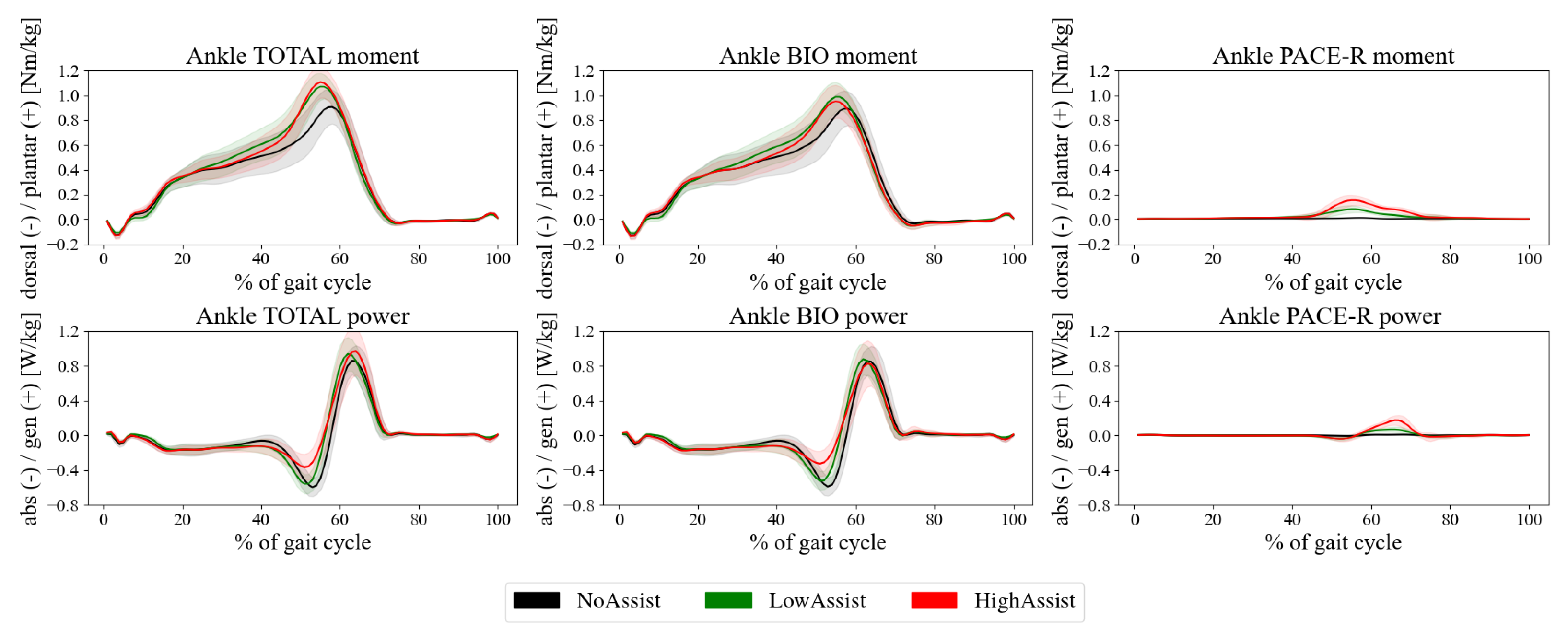
3.2.2. Analysis of the Contributions to the Ankle Total Moments and Powers
The total ankle moment and total power (denoted as TOTAL) were further decomposed into two components: The contribution from the biological ankle joint (denoted as BIO) and the combined contribution from the PACE-R module and the orthosis (denoted as PACE-R), as illustrated in
Figure 9. The results indicate that the moments generated by the biological ankle joint closely mirrored the total joint moment, albeit with a slightly reduced magnitude. Under the LowAssist and HighAssist conditions, the biological joint moment increased compared with the NoAssist condition. Specifically, the biological joint moment reached approximately 1 Nm/kg in both the LowAssist and HighAssist conditions, compared with about 0.9 Nm/kg under the NoAssist condition.
The contribution of the PACE-R module to the total ankle moment was negligible in the NoAssist condition. However, with the introduction of push-off assistance, the PACE-R contribution began increasing at approximately 40% of the gait cycle, reaching peak values of approximately 0.1 Nm/kg and 0.2 Nm/kg in the LowAssist and HighAssist conditions, respectively. This contribution then declined after the peak, tapering off by around 80% of the gait cycle. Detailed information on the individual contributions to the peak ankle moment is presented in
Figure 10a.
An analysis of total ankle power and the ankle PACE-R power during the NoAssist condition revealed no significant input attributable to the orthosis or to the PACE-R module. Under the LowAssist and HighAssist conditions, the total ankle power in the absorption phase (up to 55% of the gait cycle) was primarily derived from biological contributions. Notably, under the HighAssist condition, the PACE-R module contributed to power absorption, albeit minimally (
Figure 9).
When contributions from the biological joint (BIO) and from the PACE-R module (PACE-R) were integrated over the absorption period (
Figure 10b), representing the total energy absorbed during the gait cycle, the PACE-R module’s contribution remained negligible in the NoAssist condition and was small under both the LowAssist and HighAssist conditions. The total absorbed energy was slightly lower under the HighAssist condition (approximately 0.14 J/kg) compared with the NoAssist and LowAssist conditions (approximately 0.16 J/kg).
In contrast, during the power generation phase (approximately 55–75% of the gait cycle), the PACE-R module made a substantial contribution to total power generation, peaking at approximately 0.1 W/kg and 0.2 W/kg under the LowAssist and HighAssist conditions, respectively. The biological contribution to peak ankle power generation during push-off remained consistent across all experimental conditions.
Further analysis of the integrated total power during the generation phases (total energy generation) is shown in
Figure 10c. This analysis revealed progressively larger total energy generation with increasing push-off assistance (LowAssist and HighAssist). The PACE-R module’s contribution to total energy generation was higher in the HighAssist condition, accounting for approximately 0.03 J/kg out of the total 0.15 J/kg, compared with approximately 0.01 J/kg in the LowAssist condition.
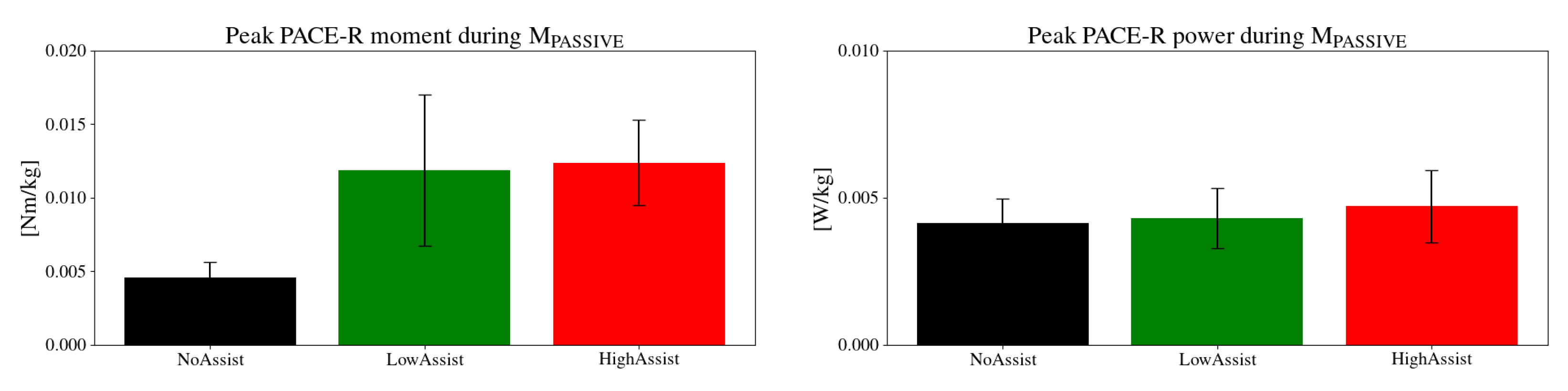
3.2.3. Transparency Analysis
Figure 11 illustrates the peak contributions of the PACE-R module to the peak ankle moments and powers during periods outside of push-off assistance, under all three experimental conditions: NoAssist, LowAssist, and HighAssist. Under the NoAssist condition, the peak PACE-R moment reached almost 0.005 Nm/kg, contributing approximately 0.5% to the peak ankle joint moment. In contrast, with push-off assistance (LowAssist and HighAssist), the peak PACE-R moment increased to approximately 0.012 Nm/kg, representing approximately 1% of the peak ankle joint moment. Conversely, the peak contribution of the PACE-R module to the peak total ankle power remained consistent across all experimental conditions, staying below 0.005 W/kg, or approximately 0.5% of the peak total ankle power.
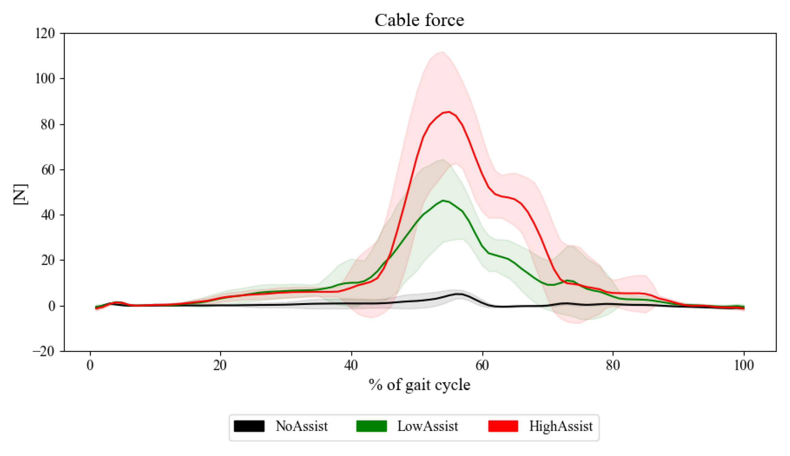
Figure 12 further illustrates the average cable force throughout the gait cycle under NoAssist, LowAssist, and HighAssist experimental conditions. In the NoAssist condition, cable force was nearly non-existent across the entire gait cycle, with only a minor peak observed around 60 % of the gait cycle - coinciding with the rapid transition of the ankle from extreme dorsiflexion to plantar flexion during push-off. In contrast, both the LowAssist and HighAssist conditions exhibited a distinct, approximately bell-shaped cable force profile only during the push-off phase, reflecting the active assistance provided by PACE-R. Outside of the push-off phase, during the M
PASSIVE mode of operation, cable force consistently remained well below 10 N.
4. Discussion
4.1. Characteristics of the PACE-R Module
A benchtop experiment demonstrated that the PACE-R module can generate force impulses with various amplitudes and durations in a highly repeatable manner. The stationary force amplitudes were found to be proportional to the motor controller set value (VREF), making them highly predictable.
The observed delay times were very small and consistent across all experimental conditions. They were attributed to the design characteristics of the fork, particularly the fork’s gap being wider than the cable. This necessitates a minimal rotational angle of the fork before it can apply a pulling force on the cable, which is associated with the delay time. Future development efforts will focus on minimizing this delay by refining the geometry of the fork reel and the swivel to better match the gap width to the cable dimension.
Oscillations in the force profiles are likely related to the limited stiffness of the cable used in the experiment. The cable, composed of densely woven fabric threads forming a flat, narrow belt, ensures a large contact surface for clamping against the fork reel. However, this design inherently introduces a degree of elasticity. Future plans include reducing these oscillations by replacing the fabric-based cable with more rigid alternatives, such as steel wire cables.
Finally, the benchtop experiments revealed a return time required for the cable to fully unwind from the fork, with the longest duration measured at approximately 250 ms. This return time effectively defines the minimum interval required between two consecutive MACTIVE modes of operation. Adjustments to the return time may be possible by replacing the tension springs in the PACE-R module with springs of different stiffness. Increasing the stiffness could shorten the return time by applying greater torque to the winding reel, while decreasing the stiffness would likely extend the return time due to reduced torque.
However, altering spring stiffness also affects the tension force of the cable during the MPASSIVE mode of operation, thereby affecting the transparency of the PACE-R module. Specifically, higher stiffness would increase the tension force, reducing the transparency, whereas lower stiffness would decrease the tension force, enhancing the transparency. As the winding reel is designed to be lightweight with minimal inertia, its dynamic properties have a minimal effect on the transparency. Conversely, the low tension force exerted by the compliant tension spring is the primary factor determining the transparency of the PACE-R module, whereas the inertial contributions remain minimal. Appropriate compromises must be made to balance acceptable tension forces and return times, tailored to the specific requirements of rehabilitation scenarios.
4.2. Push-Off Assistance Demonstration
The demonstration of push-off assistance in consecutive strides highlights an example in the field of rehabilitation where the PACE-R module was effectively utilized. The results indicate that the proposed PACE-R module, together with an orthosis, contributed approximately 0.2 Nm/kg and 0.2 W/kg of additional plantar flexion moment and power, respectively, to the biological ankle moment and power. These contributions represent roughly 20% of the peak total ankle moment and power, aligning with values reported in the literature for state-of-the-art ankle exoskeleton emulators providing bilateral assistance at the ankle joints [
48]. The additional joint moment facilitated by the PACE-R module resulted in an increase in energy generation by approximately 0.03 J/kg, accounting for about 20% of the total generated energy.
Furthermore, the PACE-R module, in combination with the orthosis, demonstrated high transparency during intervals outside the push-off assistance phases. Transparency analysis revealed that the PACE-R module’s contributions to the peak total ankle moment and power were approximately 0.012 Nm/kg and 0.005 W/kg, respectively, corresponding to about only 1% and 0.5% of the peak total values, respectively. Consequently, gait kinematics and kinetics remained effectively unchanged across all gait subphases except during push-off, where assistance was provided under LowAssist and HighAssist experimental conditions.
4.3. Control
The control scheme implemented with the PACE-R module exhibits a simple behavior analogous to an on–off switch: The PACE-R motor is either engaged or disengaged based on whether the module’s intervention is required, and the level of assistance is determined by the VREF and the duration of the impulse. This strategy, combined with the primary design feature of the PACE-R module—mechanical coupling of the cable with the motor only when the motor is engaged—provides several key advantages for rehabilitation applications, as highlighted in the literature.
First, such a simple design and control inherently enhance safety, as the user is exposed to the source of energy only during interventions, while mechanical decoupling during non-intervention periods minimizes potential risks.
Also, the mechanical decoupling of the motor and the cable eliminates the need for complex closed-loop control schemes. Advanced techniques, often employed to regulate cable tension in the state-of-the-art systems, frequently rely on additional measurement systems such as force and kinematic sensors. In the PACE-R module, such complexities are avoided, as tension is managed entirely by a passive tension spring. This design, to a great extent, bypasses issues such as motor inertia effects and latencies caused by control, contributing to more efficient operation. The passive tension spring ensures a highly transparent behavior, a critical mechanical characteristic for rehabilitation robots. This feature enhances the user experience while maintaining a simplistic design and control.
The simplicity of the design and control makes the PACE-R module robust, reliable, and capable of delivering consistent results, as demonstrated in benchtop and push-off assistance experiments. Furthermore, the straightforward design contributes to relatively low production costs, while its ease of operation allows for quick donning and doffing. These features are particularly desirable in rehabilitation settings [
49], as they promote greater accessibility and usability for patients and practitioners alike.
4.4. Potential Use of PACE-R Module in Rehabilitation
The PACE-R module exhibits potential for effective utilization across various rehabilitation scenarios. One application involves augmenting ankle joint moment and power generation during the push-off phase, as successfully demonstrated in this study in the experiment on push-off assistance.
Another promising application is perturbation-based training, which is aimed at improving dynamic balance during walking. This approach employs various methods to induce controlled perturbations, such as delivering short impulses in different directions to the pelvis, simulating slips with moving walking surfaces, or presenting sudden obstacles to the swing leg to emulate trips. The PACE-R module could serve as a versatile source of force impulses, generating targeted forces to the pelvis in arbitrary directions, pulling the foot upon contact to mimic slips, or exerting posterior pulls on the swing leg during the swing phase to emulate trips.
Additional scenarios include swing assistance, which requires short bursts of energy to initiate the ballistic movement of the swinging leg, or gait symmetry training for stroke rehabilitation. In the latter, force impulses directed toward the paretic side during the early stance phase could prolong the stance duration on the affected side, promoting improved symmetry. These tasks are often performed manually in conventional rehabilitation settings.
A key advantage of the PACE-R module lies in its modularity and portability. A single module could be positioned near existing treadmills in rehabilitation facilities, allowing for versatile use across multiple scenarios. Alternatively, multiple modules could be employed simultaneously to combine and enhance various training approaches. When combined with the additional benefits outlined earlier, this system offers a cost-effective and versatile solution that has the potential to increase access to some of the essential rehabilitation methods.
4.5. Limitations of the Study
4.5.1. Open-Loop Control
While mechanical decoupling in the PACE-R module offers significant advantages—most notably, the ability to passively maintain cable tension using a tension spring, which enables simple open-loop, on–off-style control—it also introduces a key limitation: an inherent “dead zone”. This dead zone, a result of the mechanical decoupling, allows the cable to disengage from the motor but limits the ability to achieve precise force or position control during transitions between active and passive modes. Such precision is often essential in admittance- or impedance-controlled rehabilitation robotics. As a result, the PACE-R module is not intended to provide continuous guidance throughout the gait cycle based on predefined kinematic or force profiles, as is common in traditional rehabilitation robots. Instead, it is better suited for rehabilitation applications that require targeted energy impulses during specific subphases of the gait cycle.
4.5.2. Transition from MACTIVE to MPASSIVE During Push-Off Assistance Demonstration
The results of the benchtop experiments cannot be directly extrapolated to the push-off assistance demonstration, particularly regarding the transition from MACTIVE to MPASSIVE, which represents the initial and very brief period of the MPASSIVE mode of operation. In real-use scenarios, the fork element is typically rotated by a certain angle, with a portion of the cable wound around it, and the user may apply a pulling force on the distal end of the cable—especially when moving away from the PACE-R module. These dynamics are absent in the benchtop setup due to its simplified design.
At the end of the MACTIVE phase, the VREF signal drops almost instantaneously from a high to a low value, effectively switching the motor to a passive state. This marks the beginning of the transition phase. During this period, the unwinding torque needed to return the fork element to its minimum angle position (min) is generated by the tension spring and any user-applied pulling force. The transition concludes once the fork element reaches min.
It is only during this transition that the user is subjected to the combined inertia of the motor rotor and the fork element, which may introduce a transient force and affect perceived transparency. The magnitude of this effect depends on several factors, including the rotational inertia of the system components, the rate of transition, and the user’s interaction dynamics.
First, if the fork element were to rotate multiple times during the MACTIVE phase, the cable would be wound in multiple layers, leading to overlapping. This overlap could delay the unwinding process of the fork, cable, and motor, potentially prolonging the transition phase and increasing unwanted cable forces. However, in the case of push-off assistance, the amount of cable wound onto the fork reel is directly linked to the movement range of the Bowden wire attachment point on the orthosis, which itself corresponds to the ankle joint’s range of motion during push-off.
Assuming the ankle moves from 15 degrees dorsiflexion to 15 degrees plantar flexion during push-off, and given a wire lever arm rwire = 10 cm, approximately 5 cm of cable would be wound onto the fork. With the fork element having a circumference of about 115 mm, this translates to less than half a full rotation during MACTIVE. Therefore, in the context of the push-off demonstration, cable overlapping is not possible.
Second, since the fork element rotates less than half a turn during MACTIVE, the time required for unwinding is relatively short. In fact, if an additional distal force is present—such as from a body segment moving away from the PACE-R module—this force actively assists the unwinding process. As a result, the transition from MACTIVE to MPASSIVE is shortened compared with a scenario where the unwinding is driven solely by the tension spring. This assistance reduces the duration during which the user is exposed to the inertia of the fork element and motor, thereby improving the overall transparency of the system.
Finally, the effects of unwinding would be most noticeable if the selected body segment were to move rapidly away from the PACE-R module. However, this scenario is unlikely, as the primary purpose of the assistive force is to guide and support the desired movement. For the body segment to move rapidly in the opposite direction, it would first need to decelerate, reverse direction, and then accelerate quickly away from the device—an unlikely sequence during typical assisted gait.
Considering the low inertia of both the fork element and the motor, we believe that although a cable force is present during the transition phase, it decreases rapidly and has minimal impact due to the short duration of this force. This observation is supported by
Figure 12, where the low tension force during M
PASSIVE is clearly distinguishable from the high assistive force during M
ACTIVE, indicating that the system reliably switches between the two modes across consecutive gait cycles. Other gait velocities will be considered in the future. No further formal analysis of the transition phase was conducted because V
REF and the fork element’s rotation—both of which could be used to accurately determine the transition period—were only recorded during benchtop experiments. In contrast, the push-off assistance experiment focused primarily on capturing gait kinematics and kinetics.
4.5.3. Presence of Elastic Element in the Push-Off Demonstration Experiment
To attenuate the force impulse during the transition from the PACE-R module to the attachment point, the cable in the push-off demonstration experiment was connected to a Bowden steel wire through an elastic element. In general, a series of springs can introduce complex dynamics when subjected to external forces, potentially impacting the overall system dynamics. To ensure that the elastic element primarily influences the MACTIVE phase while minimizing its impact during MPASSIVE, two criteria were applied during the selection process.
First, the selected elastic element was an elastic tendon rather than a spring, which is particularly important for the transition from MACTIVE to MPASSIVE. In this transition, the elastic element shifts from being fully loaded due to motor actuation in MACTIVE to nearly unloaded in MPASSIVE. Unlike a spring, which alternates between compression and tension and can introduce oscillatory behavior, an elastic tendon in the absence of external force simply returns to its prestretched neutral length without compressing, effectively attenuating further oscillations.
Second, the stiffness of the elastic element must be significantly higher (we selected one with stiffness approximately 2050 N/m) compared with that of the tension spring, which has an almost flat stiffness profile. In general, when a series of two springs is subjected to external forces, the resulting dynamics can become quite complex. If both springs have equal stiffness, they act as a single combined spring, with neither spring dominating the other. When their stiffnesses differ moderately, applying force introduces complex dynamics. However, if one spring is considerably stiffer than the other, the system’s dynamics is dominated by the more compliant spring while the other behaves as a rigid component. In the case of the PACE-R module, this ensures that during MPASSIVE, the system’s behavior is dominated by the tension spring, while the elastic element effectively acts as a rigid segment. This design mitigates complex and potentially unstable dynamics in the cable.
An analysis of the cable force in
Figure 12 shows that the addition of the elastic element results in a bell-shaped force profile during M
ACTIVE, rather than the impulse-like profile observed in the benchtop experiment. However, throughout the rest of the gait cycle, the cable force does not appear to be influenced by the added elastic element.
However, the addition of the elastic element and the resulting challenging dynamics could potentially be mitigated by replacing the impulse-like profile of the motor controller reference (VREF) with an alternative that exhibits a more gradual rise. Future work will explore different VREF profiles, such as ramped or sinusoidal profiles, which may reduce the sudden occurrence of large forces at the attachment point and enable smoother force transitions.
5. Conclusions
In this study, we present a novel principle for applying force impulses in cable-driven rehabilitation robots, embodied in the PACE-R module. The key feature of this design is the mechanical decoupling of the cable from the motor when intervention is not required. During these periods, cable tension is maintained by a low-stiffness tension spring. This approach eliminates undesirable inertial effects from the motor and obviates the need for complex tension control strategies, which often introduce latencies and limit the level of transparency achievable in cable-driven robotic systems.
As a result, the PACE-R module achieves a highly transparent mechanism, as demonstrated in a push-off assistance experiment. Additional advantages of this design include reliability, robustness, short donning and doffing times, and cost-effectiveness—characteristics that are particularly desirable in rehabilitation applications. Beyond push-off assistance, the PACE-R module has potential applications in gait symmetry training, perturbation-based training, swing assistance, and other rehabilitation tasks, making it a versatile and valuable tool for clinical use.


 ,
, 