Article

Design, Fabrication, and Experimental Validation of Optical Microbots

by
Menaka Konara
1,
Mishal Pokharel
2,
Md Mainuddin Sagar
1,
Yeongjin Kim
3,* and
Kihan Park
1,*
1
Department of Mechanical Engineering, University of Massachusetts, Dartmouth, MA 02747, USA
2
Department of Biomedical Engineering and Biotechnology, University of Massachusetts, Dartmouth, MA 02747, USA
3
Department of Mechanical Engineering, Incheon National University, Incheon 22012, Republic of Korea
*
Authors to whom correspondence should be addressed.
Actuators 2025, 14(5), 229; https://doi.org/10.3390/act14050229
Submission received: 4 March 2025 / Revised: 21 April 2025 / Accepted: 23 April 2025 / Published: 5 May 2025
(This article belongs to the Special Issue Actuation and Biomedical Development of Micro/Nano Robotics)

Abstract

:
Light-actuated microbots have been studied as a viable tool for interacting with micro/nano environments. Considering their applicability to a wide range of biomedical applications, novel designs, fabrication techniques, and control methodologies are being developed. Especially, micro/nanoscale three-dimensional fabrication techniques have opened many possibilities for developing microbots with complex geometries using resins as materials. Here, we developed microbots that can be actuated with tightly focused laser beams to be used in targeted drug delivery, cell poking, and cell characterization studies. These microbots were fabricated in batches using two-photon polymerization (TPP). Each microbot utilizes a deposited metal layer inside its body to manipulate convective microfluidic flows. Additionally, micro-sized end effectors allow them to make measurable physical contact with biological objects. Their expected performance was evaluated using numerical simulations with the use of multiphysics software. Furthermore, laser-induced loading and unloading of micro-sized cargo show their capability for in vitro applications.

1. Introduction

Microelectromechanical Systems (MEMSs) are devices with design features at micro/nanoscale dimensions. They have a wide range of uses with the development of micromechanical [1,2], micromagentic [3], microthermal [4], micro-optical [5], and microfluidic [6] devices. Among them, microfluidics has gained significant interest due to its applicability in small volumes of fluids. This has led to the emergence of microrobotics as a new research field for making miniature tools for microfluidic studies. Developing these systems has its own set of challenges. At smaller scales, with the increase in the surface-to-volume ratio of these devices, surface forces become more dominant. Consequently, entirely different approaches are required to design, fabricate, and control microbots for specific microfluidic applications. Non-invasive access to smaller spaces, parallel operation, and the biocompatibility of these units benefit a wide range of biomedical applications [7].
Given the size of the microbots and their working environments, the properties of low Reynolds number (Re < < 1) flows must be considered. In those flows, as E.M. Purcell [8] explained in his well-known article, inertial forces become irrelevant. Viscous forces dominate the interaction between micro-sized objects and the surrounding fluid environment. This is an important factor to be considered while designing microtools for microfluidic applications [2]. When micro-organisms are considered, they rely on asymmetric, non-reciprocal motions [9] to generate thrust for motion in low Re flows. These properties have been used as a propulsion technique for swimming microbots [10,11]. Furthermore, their untethered nature requires design features that help microbots receive forces for motion from external fields. Also, maintaining structural integrity, ensuring stability during motion, and meeting application-specific requirements have to be considered during the design process [12].
The fabrication of miniature devices at smaller scales has been a challenging task. While larger robots at the macro scale can integrate controllers and power sources, microbots cannot due to their limited body volume [13]. Instead, external energy fields such as magnetic [14], electric [15], thermal [16], and optical [17] are mostly used to control microbots. For effective control, microbots need to be fabricated from specialized materials. Dielectric, ferromagnetic, and high-refractive-index materials are chosen based on the actuation principle. In recent years, micro three-dimensional (3D) fabrication techniques have become a valuable tool for transforming complex designs into functional realities. Stereolithography [18], digital light processing [19], continuous liquid interface production [20], laser-induced forward transfer [21], and two-photon polymerization (TPP) [22] are the most commonly used printing techniques. Among these, TPP offers the highest resolution (about 100 nm); however, its point-by-point nature slows down the printing process [23]. These techniques utilize materials such as SU-8, hydrogels, and IP-series resins. Additionally, a growing number of new materials having biocompatible, conductive, and optical characteristics enables the integration of enhanced functionalities into microbots [24]. Microbots fabricated from biocompatible materials have the potential to bridge the gap between proof-of-concept studies and clinical trials, paving the way for real-world medical applications [25].
Different types of light-based control techniques are used to manipulate microrobots. Optical tweezers (OTs) [26], optoelectronic tweezers (OETs) [27], and electrothermoplasmonic nanotweezers [28] are a few examples. Among these, OTs have been the most widely used concept. They use the momentum transfer between light and microscale units to manipulate these miniature units. Although the momentum transfer due to the refraction of light is small, its effect on microunits with smaller mass is considerably high [29]. A high-power focused laser can trap micro/nanounits along the beam axis. This principle, first discovered by Arthur Ashkin, paved the way for diverse applications that leverage light for handling micro/nano-objects [30]. Similarly, microbots need to be trapped using light before executing a motion in a microfluidic channel. The trapped units can then be moved by shifting the optical trap locations in a required trajectory. OTs rely on high-power laser beams, with light tightly focused using high numerical aperture lenses before the light reaches the microbot sample. The maneuverability and complexity of control highly depend on a system that is used for creating optical traps. Most of the microbots with complex 3D geometries require more than a single optical trap for better controllability. In such cases, multiple optical traps must be created. Many systems achieve this using time-sharing techniques, where the light beam moves rapidly between multiple coordinates, simulating the presence of multiple optical traps. Several studies have used spatial light modulators [31] and Galvo scanners [7] to create multiple traps for microrobot manipulation.
As non-tethered tools, light-controlled microbots have shown great potential for a wide range of biomedical studies. Cell manipulation is a process that allows for cell sorting, advanced microscopy, and the selective delivery of biomolecules [32]. However, the direct manipulation of cells using OTs has raised concerns about photodamage to cells. Indirect manipulation of yeast cells by V-shape-headed microbots [33] and fork-shaped tools [34] demonstrate the use of microbots to address this issue. Additionally, novel micromechanisms with rotatable mobile heads have been developed for dexterous cell handling [35]. Cell perforation is a technique used to create openings in the outer membranes of cells, allowing for the insertion of DNA and RNA [36]. Cell puncturing was tested using a hybrid nanobot that uses an integrated carbon nanotube for creating holes on stained cells [37]. Moreover, evaluating the mechanical properties of cells gives useful information for cancer diagnosis and immune status [38]. For instance, increased cell deformability is often an indicator of cancer progression. Studies using microbot-assisted lateral probing have been conducted to determine the Young’s modulus values of endothelial cell walls [39]. Another cell characterization application of microbots is in temperature measurement, with silicon nanowire-based thermal probes offering insights into cellular microenvironments [40].
Targeted drug delivery has been a well-explored topic in microrobotics, enabling higher concentrations of drugs to be delivered to specific therapeutic zones and reducing the effect on healthy tissues. However, the direct manipulation of multiple drug particles by laser light can not only slow down the process but also lead to photodamage [41]. Overcoming this indirect manipulation of drug particles can be performed with the help of microbots that can deliver particles as cargo [42]. Laser-induced thermal convection provides a way to generate microfluidic flows using high-power laser beams for this objective. Previous studies have demonstrated the use of the concept for microfluidic mixing studies [43], functional micropumps [44], and the optofluidic flow control of nanoparticles [45] and cells [46]. Numerical simulations further confirm that laser-induced heating effectively generates convective flows [46]. Microtools with gold-coated disks [47] and microbot vehicles with heat sources [31] have demonstrated the concept of microparticle manipulation using optical microbots. The literature suggests that this concept could serve as a potential microparticle loading technique using optical microbots.
Many current optical microbot studies have been focused on developing microbots for single specific tasks. However, a microunit with multiple functionalities can be highly beneficial. To achieve this versatility, microbots must incorporate specialized design features. In this study, optical microbots were developed for cell characterization, cell poking, and targeted drug delivery. The content of this study is structured as follows. First, three microbot designs are introduced, highlighting their features and expected functionalities. In the later sections, fluid flow simulations, fabrication processes, and cargo loading and unloading experiments are discussed.

2. Design of Microbots

In this study, three main designs have been considered. Although they are intended for the same applications, several design variations have been incorporated to analyze performance differences. Given the common requirement that the microbots must be operated using an OT setup, each design includes optical handlers that serve as actuation points for the microbot. Optical traps will be aligned with these handlers in 3D space. To optimize performance, the size of the optical handlers should be limited [48]. This size constraint primarily ensures higher trap stiffness, which is crucial for maintaining stable microbot motion. Larger optical handlers are more challenging to trap due to the increased scattering force, whereas excessively small handlers generate a weaker refraction effect, reducing trapping efficiency. Optical handlers are connected to the main body of the microbot using leg-type structures. The length of the legs should be long enough not to expose the body to the laser beam during trapping, which can destabilize the microbot and make the trapping process complex. Furthermore, a symmetric design has been maintained to ensure stable manipulation of the microbot using optical traps. Considering the motion capability of the units, all design versions can be moved in a two-dimensional plane by changing the trap locations. They can perform linear motion along longitudinal and lateral directions. Additionally, a rotation around a central axis that goes through the center of traps is also possible. Overall, microbots are proposed to have three degrees of freedom.
Each microbot is designed to function as a cargo-carrying, micro-sized vehicle, with the ability to load, transport, and unload microparticles. The body features a large internal volume with inlets and outlets to facilitate the controlled movement of microparticles. The diameter of the inlet should be large enough so that microparticles can enter through the inlet without getting stuck. It is proposed to use indirect manipulation of cargo to reduce the photodamage to micro/nano-sized cargo. For that, convective flows are a reliable technique. The generation of strong convective flows toward the microbot needs a high-temperature heat source inside the microbot chamber. Depending on the design version, each microbot is equipped with either one or two heat sources, which regulate the inflow and outflow of microparticles. A thin layer of gold will be deposited during the fabrication process to create heat sources for the microbot using a masked sputtering process. Additionally, the microbots are designed for cell poking and contact force measurements. To achieve this, two sharp-ended end effectors are integrated into each microbot.
The microbot designs presented in this study incorporate the aforementioned features, demonstrating multifunctionality and enabling more dexterous performance compared to previously reported microbots. For instance, the microbot with a single heat source described in [31] is capable of loading and unloading microparticles but is not designed for multiple applications. Similarly, the microtool in [47] can manipulate fluid flows only outside its body and lacks the ability to transport cargo. To the best of the authors’ knowledge, the use of a dual-heat-source approach for manipulating microfluidic flows within a microbot has not been previously demonstrated. In addition, the integration of multiple inlets and chambers for separate loading and unloading channels introduces new opportunities for laser-induced microcargo manipulation using optically controlled microbots. Existing microbots with fork-shaped [34] and V-shaped [33] end effectors, developed for cell manipulation, do not include cargo-handling capabilities. Further, microbots designed for cell puncturing [37] and force measurement [39] are limited to specific cell–microbot interaction tasks. The next section details the design features of three multifunctional microbots developed to address these limitations.

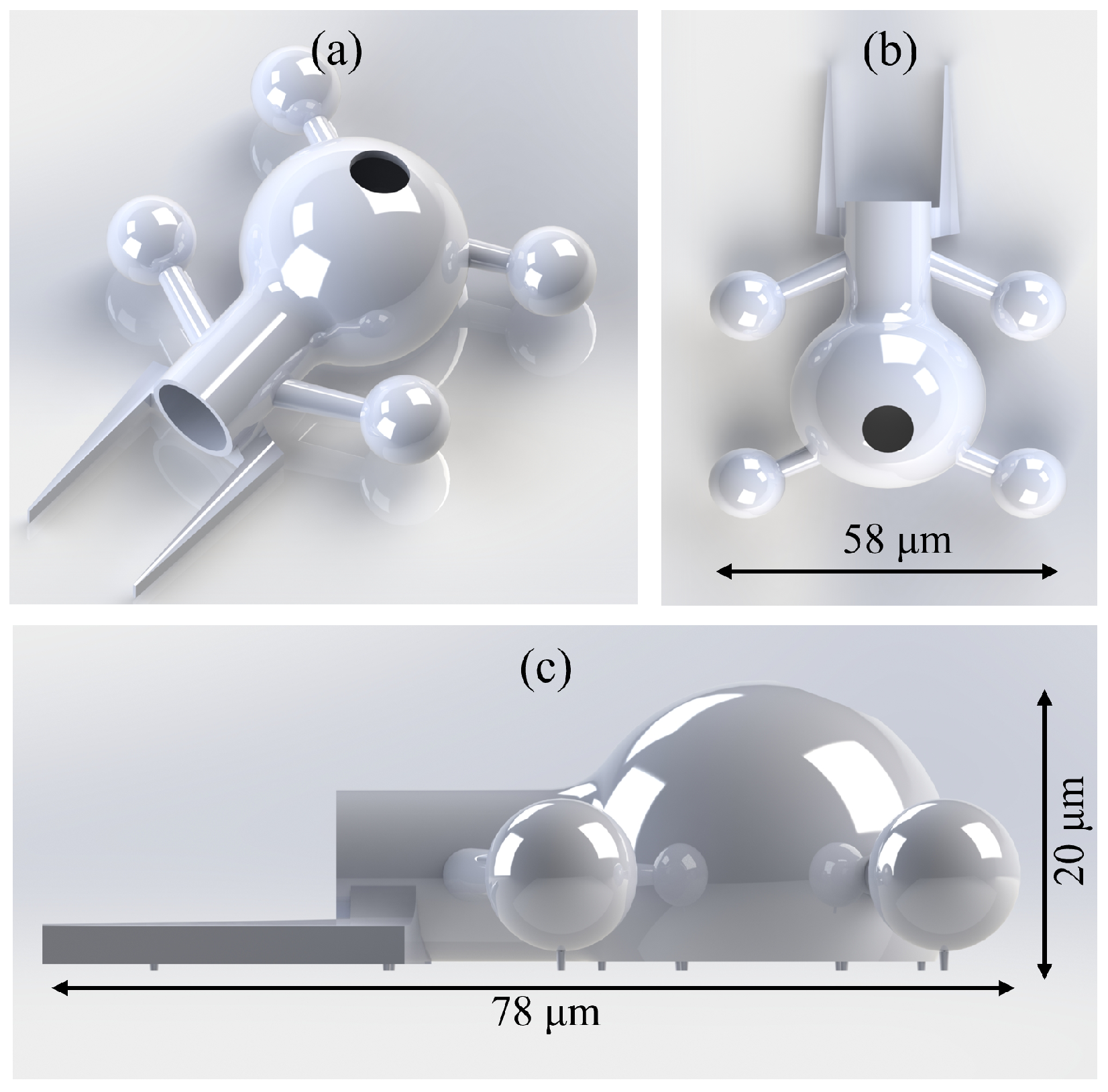
2.1. Design Version 1

The first version is a modified version from our previously presented study [49]. As shown in Figure 1a, the microbot has four optical handlers. Additionally, a front inlet serves as a channel for loading cargo into the microbot chamber. The inlet is designed with a diameter of 10 μ m to facilitate the transport of sufficiently large cargo via convective currents. A top hole with a diameter of 7 μ m is incorporated into the microbot chamber to allow the deposition of a metal layer. A laser beam can be focused on this layer to generate a localized heat source with a high temperature. This heating is expected to induce a convective cycle, creating an inflow toward the microbot chamber. The main dimensions of the microbot are illustrated in the top view in Figure 1b. As shown in Figure 1c, two front spikes are integrated into the design to facilitate interaction with cells. Compared to the previous version, the overall size of the microbot was increased. This scaling up also increased the inlet diameter and metal spot diameter, contributing to stronger convective flows.

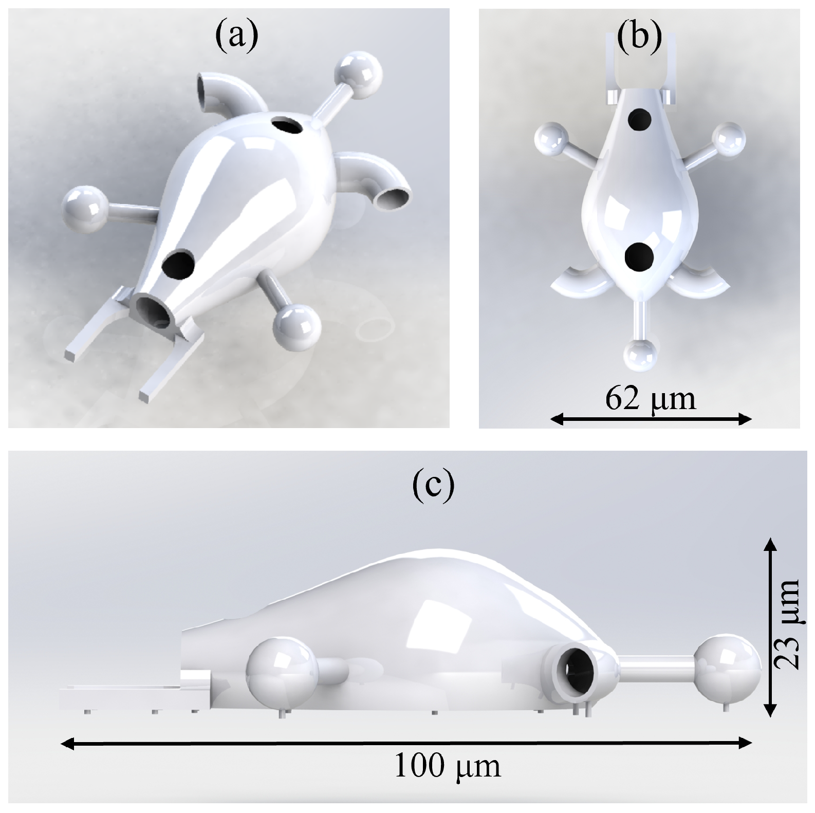
2.2. Design Version 2

The second version has several changes compared to the initial version. The four optical handlers have been reduced to three, providing additional design space. This also enhances the trap stiffness when using time-sharing methods for optical trapping. Furthermore, the design has two inlets and one outlet, as shown in Figure 2a. Two inlets that are on the front of the microbot will be used for the functionality of loading microparticles. Positioning the heat source closer to these inlets is expected to generate stronger convective flows at the openings, enhancing cargo intake from the sides of the microbot. The forward motion direction of the microbot was chosen as the side with one optical handler. To minimize unintended cargo release during motion, the two inlets were designed with a bent shape to reduce inflow. As shown in Figure 2b, the microbot features two top holes, both designated for metal layer deposition to serve as heat sources. The metal layer closer to the inlets has a diameter of 7 μ m and will be used for loading microparticles. The additional one at the back of the microbot with a 5 μ m diameter can be used as an unloading flow generation heat source. About a 40 μ m distance should be maintained between the two heat sources to prevent simultaneous heating. To accommodate this, the microbot’s length has been increased compared to version 1. Additionally, end effectors have been integrated for cell interaction applications at the back of the body.

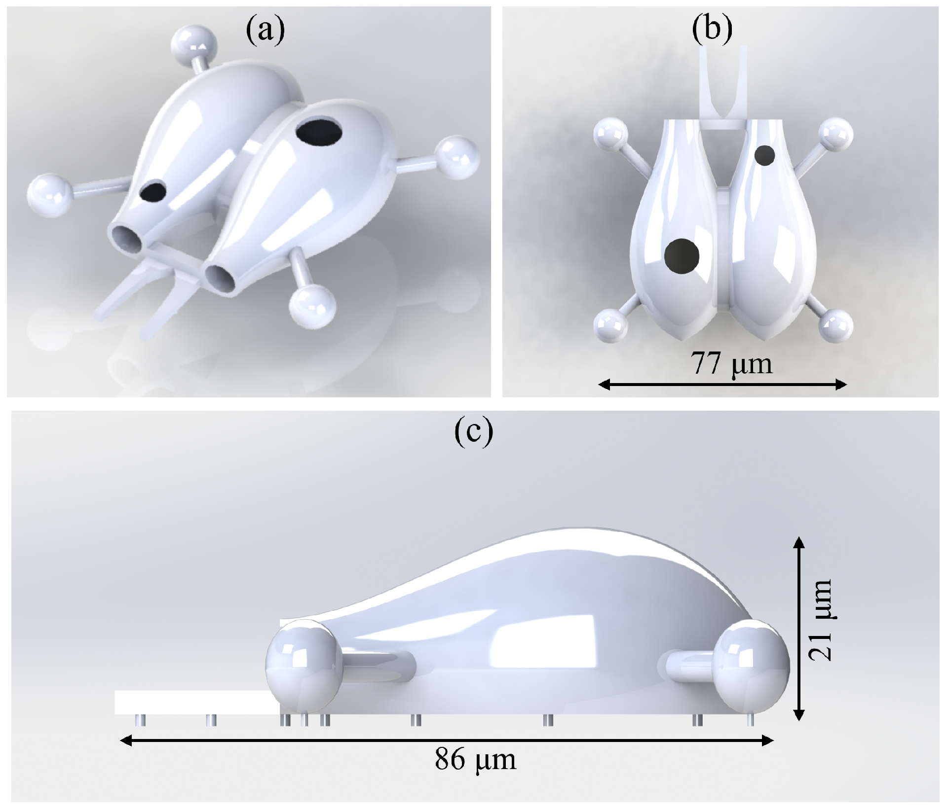
2.3. Design Version 3

The third design features two chambers for storing cargo, increasing the overall cargo capacity of the microbot. Additionally, this version incorporates two heat sources. The left chamber contains a heat source with a 7 μ m diameter, while the right chamber has a spot with a 4.5 μ m diameter. Microparticles will be loaded through the left inlet to the microbot body using the heat source in the left chamber. The second chamber has a heat source positioned closer to the outlet, which will be used for controlled cargo unloading. When the heat source in the right chamber is activated, it should generate an outward flow, directing micro-sized cargo toward the right chamber’s outlet. This configuration allows loading and unloading to be performed independently through separate chambers. Similar to the other two versions, micro-sized end effectors were included in the design for cell interaction studies. The main dimensions of the microbot are shown in Figure 3.

3. Multiphysics Simulations

Multiphysics simulations were conducted to analyze the behavior of convective flows under localized heating and flows during microbot motion. All simulations were performed using COMSOL Multiphysics 6.2 software. Experiments were run on a XPS 15 9530 computer (Dell Technologies, Round Rock, TX, USA) with an Intel 13th Gen Core i9 processor, 32 GB of RAM, and running Windows 11. To reduce the complexity of the convective flow study, a simplified version of the microbot has been used for each simulation. This significantly reduces the computation time and avoids any numerical errors that can be generated during simulations due to the complexity of microbot design. To define the boundary conditions that represent the application, creeping flow, and heat transfer between solid and fluid interfaces has been used, along with non-isothermal multiphysics. During the simulation, laser heating was added as a boundary heating source. The microbot was assumed to be immersed in a 1 × 1 × 1 mm3 cube-shaped well filled with water.

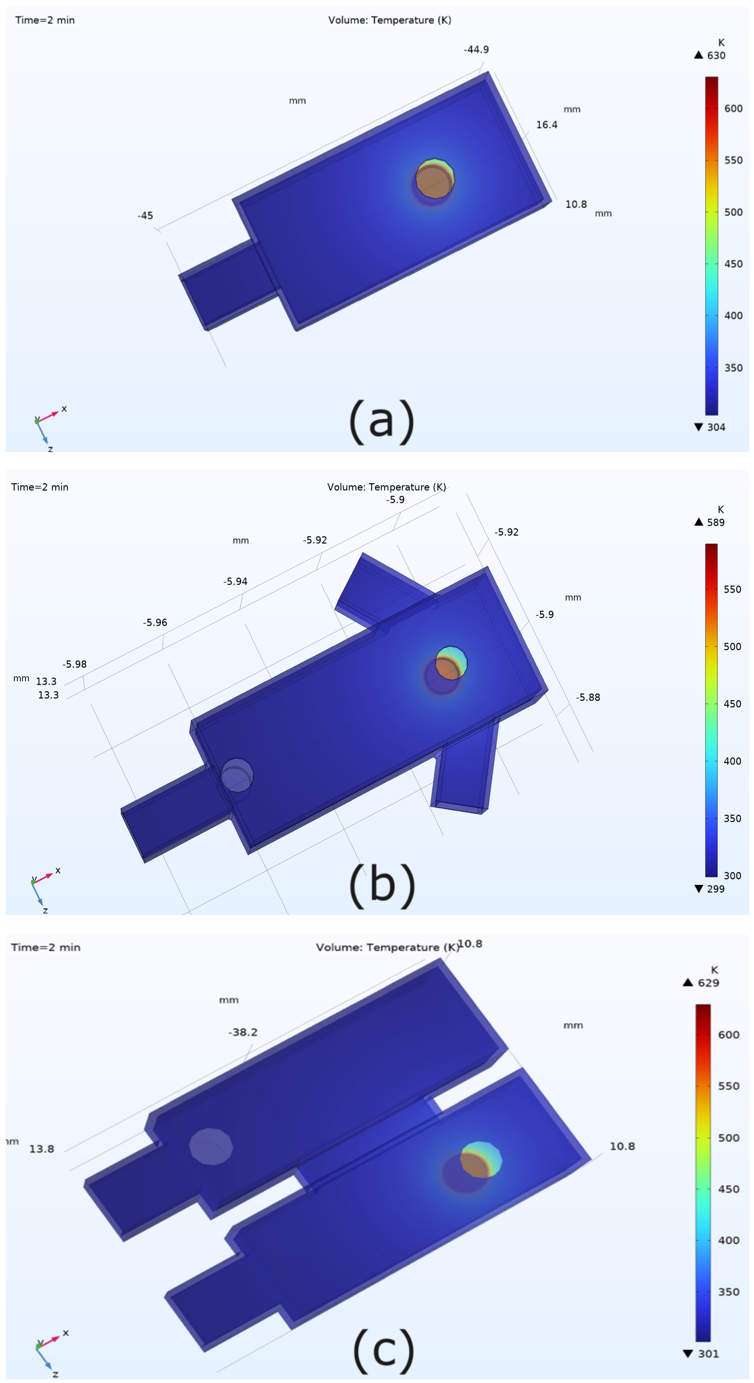
3.1. Temperature Distribution

First, a time-dependent study was conducted to analyze temperature variations inside the microbot under a given heat input. The laser power which was applied as a boundary heating to the metal layer was set to 15 mW. In the COMSOL model, the thin gold spot has a thickness of 15 nm. Simulation results indicated that the temperature increased to approximately 600 K within two minutes for all three models. The temperature distribution results for the three simplified designs are shown in Figure 4. The fluid domains are hidden in the figures to show the temperature distribution near the heat source clearly. The highest temperatures were observed in regions closest to the heat source. The results suggest that higher temperatures can be achieved within a short time period when the thin layer of gold is heated at a power input of 15 mW.

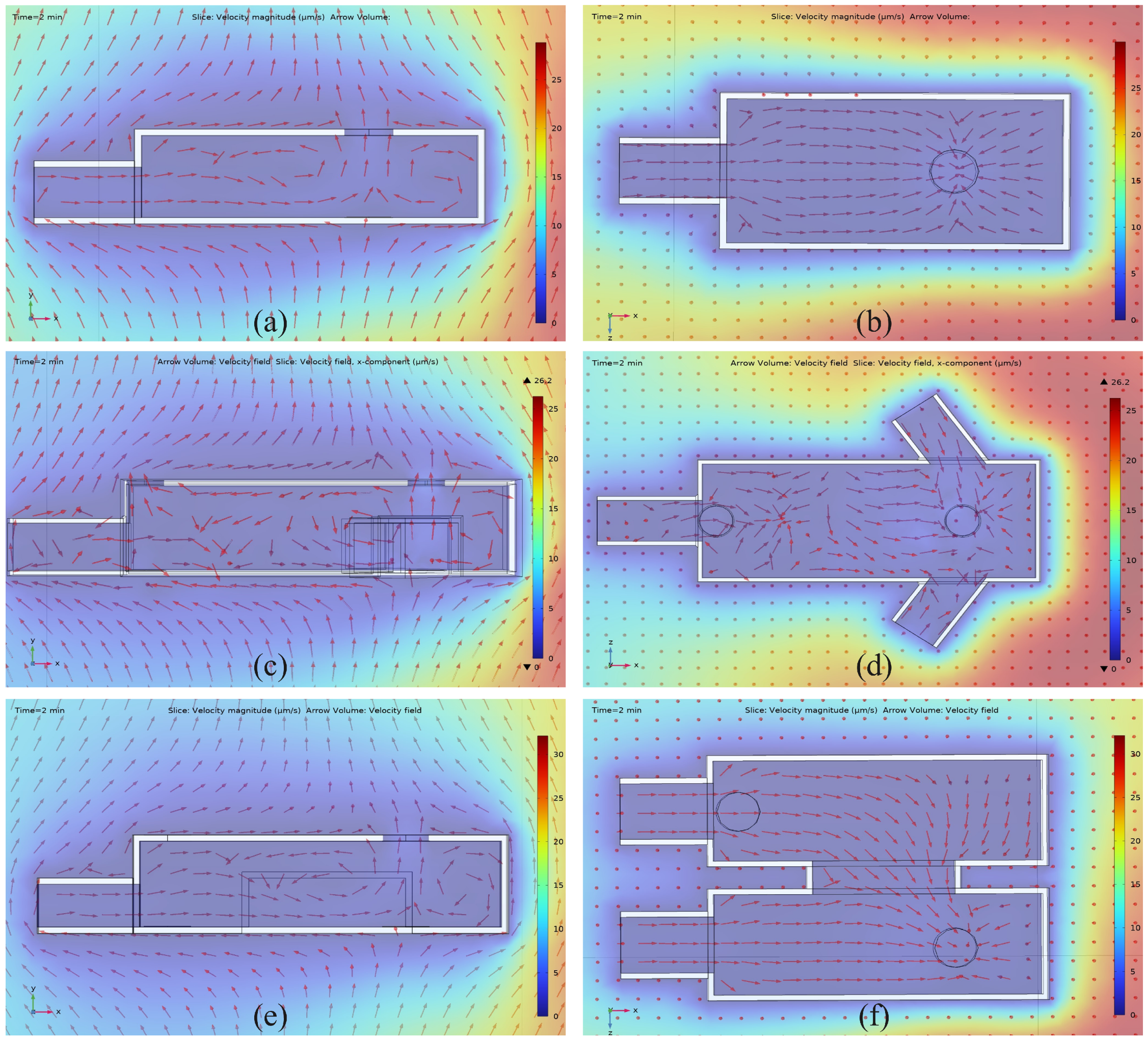
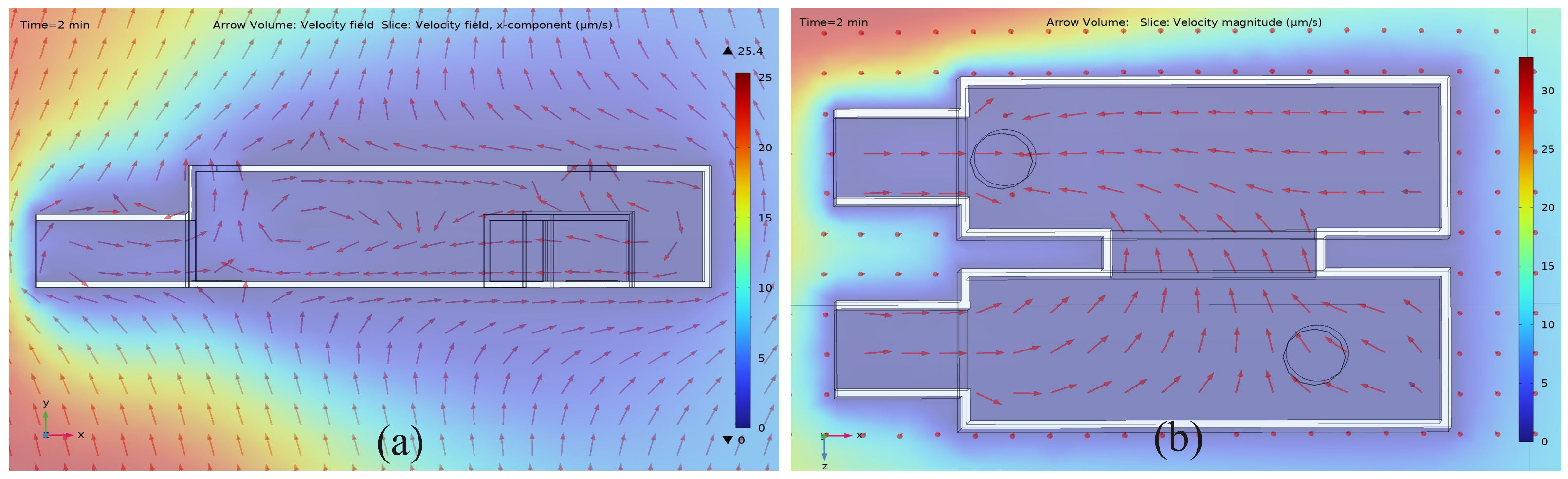
3.2. Microfluidic Flow Velocity Distribution

Loading microparticles as cargo onto a microbot depends on how convective flows behave under laser-induced heating. To analyze this, flow velocity distributions have been studied with a 15 mW heat input. Figure 5 illustrates the variation in flow velocity, with arrows indicating flow directions. For each microbot design, both a top view and a side view are presented to clearly depict the flow distribution using two cut planes. The side view represents the flow distribution extracted using a cut plane that sections the microbot along its longitudinal axis, while the top view was generated using a horizontal plane positioned just above the thin metal layer.
As shown in Figure 5a,b, in the first microbot design, fluid flows from the inlet toward the chamber. Due to the higher temperature near the heat source, the fluid moves vertically from the chamber, creating a convective cycle. The velocity of these flows is approximately 1–5 μ m/s based on the results. For the second version, fluid enters the microbot through two inlets positioned near the heat source, as shown in Figure 5c,d. Additionally, there is an inflow from a third inlet directed toward the chamber. The above results confirm that a high-temperature heat source creates flows toward the microbot chamber. In the third design, the laser needs to illuminate the first metal layer in the left chamber. When this occurs, fluid enters through the front inlets and moves toward the heat source Figure 5e. As seen in Figure 5f, flow velocities from the right chamber also direct fluid toward the heat source in the left chamber. This confirms that heating the metal layer in the left chamber is an effective technique for collecting cargo from inlets into the left chamber.
Both design versions 2 and 3 have an extra metal layer to be utilized for unloading loaded cargo. The simulations were conducted to analyze fluid flows under this condition for both versions two and three. For version 2, there is a fluid flow from the chamber toward the outlet of the microbot, as can be seen from Figure 6a, which confirms the capability to use this concept as a method to move cargo toward the outlet. However, there is also an inflow from the outlet, which will reduce the velocity of the microparticles during unloading. Still, microparticles can be moved closer to the outlet, allowing for convenient unloading by moving the laser trap from the heat source toward the outlet. For the third design, it was necessary to create a flow from the left chamber to the right chamber outlet. When the metal layer in the right chamber is heated, fluid flows from the loading chamber to the unloading chamber. As shown in Figure 6b, the fluid velocity directions indicate movement from the left chamber to the right chamber through the connecting channel (Additional results are included in Supplementary Figure S1). This enables the cargo, initially loaded into the left chamber, to move toward the heat source at the outlet. Simulation results demonstrate that using two metal layers is an effective approach for unloading cargo from the microbots.
In targeted microparticle delivery applications, cargo must be transported from one location to another. However, due to fluid flow, there is a possibility that particles may drift away from the chamber. To study this behavior, a fluid flow analysis was conducted under a flow velocity of 50 μ m/s, assuming that the microbot moved forward at the same velocity. The flow distribution during this motion is shown in Supplementary Figure S2. Although the flow velocities belong to low-velocity regions, there is still a possibility that small microparticles could escape from the chamber, even at lower flow rates. This should be carefully considered in targeted delivery applications, where a microbot must be precisely guided toward a designated location.

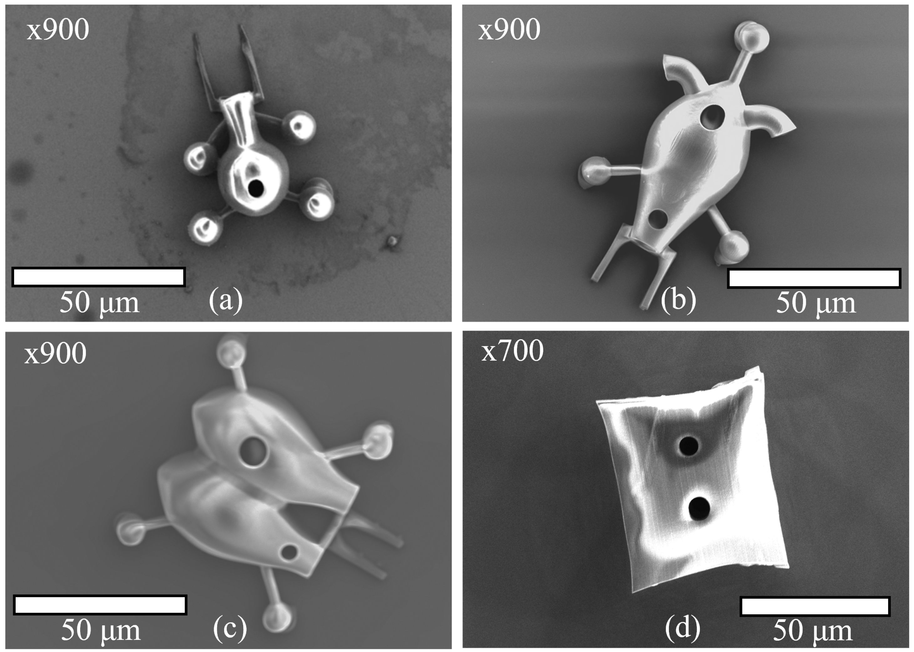
4. Microbot Fabrication

In order to fabricate designs, a commercially available laser writing setup that uses TPP for microfabrication (Nanoscribe Photonic Professional, Nanoscribe GMBH, Eggenstein-Leopoldshafen, Germany) was used. This technique offers significant advantages for fabricating complex geometries at the micro/nanoscale. Mainly, its capability to create complex 3D geometries is highly advantageous for microtool development. During the fabrication process, 3D models are converted to a file format supported by the Nanoscribe machine. Negative photoresist (IP-Dip) drops are placed on silicon 10 × 10 mm2 substrates and during the printing process, and areas of the microbot structure are polymerized by a high-power laser. Considering the properties of the material IP-Dip, it is biocompatible, which is ideal for the microbots developed in this study. It has a Young’s modulus of 2.9 GPa and a density of 1.170 g/cm3. The viscosity of the material is about 2500 times that of water. The material also has a refractive index of 1.552. A single microbot polymerization needs about 5 min for the printing process. During a single printing cycle, a batch of microbots is printed. A printing cycle is followed by a developing process using propylene glycol methyl ether acetate (PGMEA) and isopropyl alcohol (IPA). First, a substrate is submerged in PGMEA for 20 min and then transferred to an IPA solution for a 5-m interval. PGMEA dissolves unpolymerized regions of the resist, leaving behind only the crosslinked structures. IPA is used to remove residual PGMEA from the sample. Then, the sample is dried using a N2 gas flow. SEM images of fabricated microbots without masks are shown in Figure 7a–c.
Fabricated microbots are required to undergo a masked sputtering process to deposit the thin gold layer inside the microbot’s body. Therefore, masks are also included to microbot designs prior to fabrication using TPP. The design details about masks are included in Supplementary Figure S3. A version 2 microbot with the mask is shown in Figure 7d. In this way, only the top holes of the microbot are exposed to the gold sputtering. Samples were sputter-coated with gold for 2 min and 30 s using the Denton Vacuum DESK IV system. Under a 10 mA current input with argon as the process gas, a deposition rate of 0.1 nm/s was provided by the system. In this way, a thin gold layer with 15 nm thickness could be deposited inside the microbot chamber.

5. Experimental Results

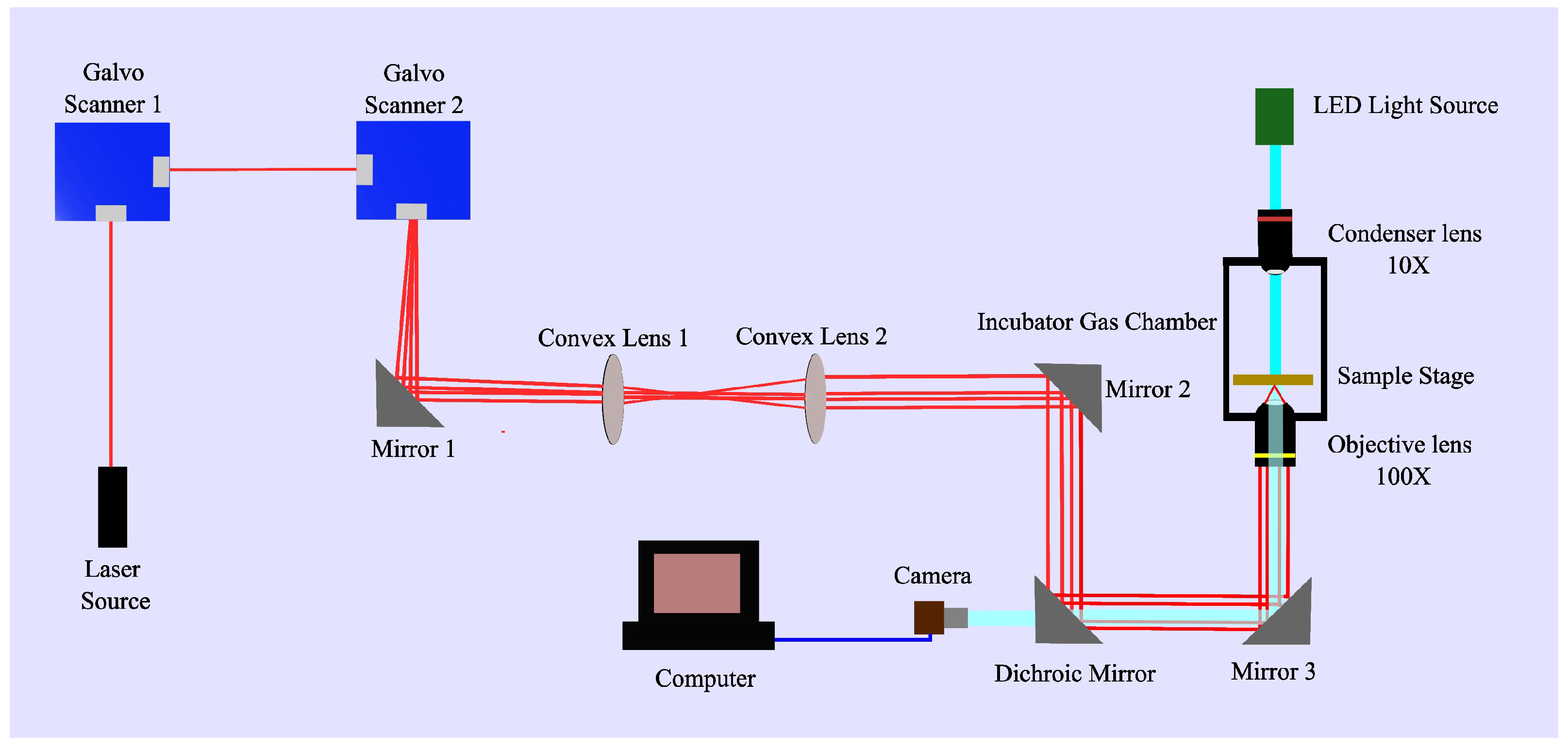
5.1. Experimental Setup

The experimental setup used in this study is a modular optical tweezer system. The OTKB system from Thor Labs has been modified to include useful functionalities to our requirements. The laser source produces near-infrared region light with a wavelength of 976 nm. The maximum attainable power output at the fiber output is 300 mW. As shown in Figure 8, the laser beam first goes through two Galvo scanners. They are used to create multiple optical traps, which are essential to manipulate microbots. After the Galvo scanners, multiple mirrors and convex lenses are utilized to create a collimated beam to fill the back focal of the 100× objective. It has a numerical aperture of 1.25, which helps to create stronger traps by focusing the laser beam to the sample, resulting in a higher gradient force. In order to illuminate the sample, an LED light source is used. A dichroic mirror allows only the LED light to pass toward the CCD camera in the system. Microbot samples can be placed on the movable 3-Axis NanoMax stage. The position of the sample can be shifted with an on-axis accuracy of 1 μ m/s using stepper motors. Using the camera feed, visual feedback of the microbot can be received. A stage-top incubator (OKOLAB, Pozzuoli, Italy) was integrated with the optical tweezer system to carry out studies with biological samples. It maintained the cells at ambient conditions maintained at 37 °C in a humidified atmosphere containing 5% CO2.

5.2. Microbot Extraction

After fabrication, it is required to transfer microbots from silicon substrates to microwell plates for experiments. This was carried out by using a stepper motor-driven ThorLabs NanoMax stage and a microsyringe unit (Supplementary Figure S4). First, using the microsyringe, a mixer of deionized water, Tween20, and 2 μ m silica beads were added to the substrate. Tween20 was used to reduce the surface tension forces acting on the microbots, which should help the microbot to flow freely. In addition, diluted silica beads were added to the sample as a tracing agent to find microbots from the microwells. First, using the syringe tip, the masks were removed. Then microbot was released from the substrate carefully. This process is shown in Figure 9. Given the smaller size of the microbot and their fragile nature, it is easy to break the structure of the microbot during this process. Released microbots were then collected using the micro syringe. Then, the fluid volume with the microbot was transferred to the microwell for conducting experiments. Given the higher probability of missing out on a microbot during this process, multiple microbots were collected to ensure a sample amount that could be used for experiments.
Collected samples were placed on the sample stage of the experimental setup, and microbot locations in the sample were found by moving the stage and observing the video feedback from the camera. The previously added silica beads were helpful in finding the area where the microbot was located. Once the positions were known, using the modular optical tweezer setup, experiments could be conducted. In order to preserve the samples, the microwell plates were closed with coverslips, while the edges of the coverslip were covered with vacuum grease to seal the sample. Then, the sample was kept in an incubator for long-term use. To prevent the sample from drying out, it is essential to periodically check the water level. The microbot extraction process is shown in the Supplementary Video S5. The steps were recorded using an BX51 microscope (Olympus, Tokyo, Japan) with 20×. magnification.

5.3. Laser-Induced Microparticle Loading and Unloading

To generate convective flows, the microbot’s heat sources were precisely targeted using the laser beam. The experiments were carried out using microbot design version 2. Silica beads with a 2 μ m diameter served as the cargo. No significant movement of the silica beads in the fluid was observed until the laser power output reached 21 mW, as shown in the Supplementary Video S6 at low power outputs. The laser output was measured closer to the front lens of the 100× objective. A laser power meter (PM100D, THORLABS, Newton, New Jersey, United States) with a photodiode sensor that can measure beams with a wavelength range of 400–1100 nm was used. At a 21 mW output under 105 mA input current, the silica beads in the surrounding area began moving toward the microbot’s inlets. Figure 10 illustrates the trajectory of a silica bead, highlighted by a red circle, as it moved toward the microbot’s inlet. This motion is shown in Supplementary Video S7. For this motion, trajectory data were extracted using the Python (Version 3.13.0) library Trackpy, which uses a set of image processing algorithms [50]. Using position data, for a 20 s period, the silica bead velocity variation was analyzed and is shown in Figure 11. The velocity values were in the range of 0.5–2 μ m/s until the beads got closer to the microbot inlet. Near the inlet, the velocity increased to over 3 μ m/s.
Increasing the power output further intensified the convective flows, resulting in rapid motion of the silica beads. Fast flow generation under 34 mW power output is shown in the Supplementary Video S8. At this power output, tracing of a particle loading through a microbot inlet with a velocity value of about 45 μ m/s is shown in the Figure 12. The reported value is much faster than previously reported silica bead velocities under laser-induced loading [31]. By giving a laser-guided disturbance to a microbot loaded with particles, it has been confirmed that the loaded particles remained in the microbot chamber (Supplementary Video S9).
At approximately 60 mW power output with an input current of 310 mA to the laser, structural damage to the microbot was observed, indicating excessive heat generation. This threshold has been identified as the upper limit for heat generation in the current microbot design.
Loaded particles were required to be unloaded at the target location. In microbot version 2, the second heating source, which was located closer to the outlet, was used for this task. Figure 13 shows the stepwise unloading of particles with time stamps under a laser power output of 21 mW. Furthermore, Supplementary Video S10 shows the recorded video for this process. At t = 0 s, it can be seen that there were loaded particles in the microbot chamber. Then, the laser was focused on the area marked by the yellow circle. This resulted in the generation of convective currents that were strong enough to draw silica beads from the microbot chamber toward the outlet.
At t = 90 s, it can be observed that most of the loaded particles had been moved out of the chamber. Then, to move all beads out of the microbot, the laser was moved along the dashed red line. This resulted in moving all beads as a cluster, demonstrating the capability of the concept to unload loaded particles. Unloaded particles can be seen outside of the microbot at t = 100 s. Furthermore, at a high power output of about 34 mW, a faster motion of silica beads through the outlet was recorded, as shown in the Supplementary Video S11. The results have shown the capability to use the unloading heat source for removing microparticles from the microbot body.

6. Conclusions

In this study, optical microbots were developed to be used in biomedical applications. During the design process, several design features were included in the microbots to successfully carry out the expected tasks. Three models were designed using Solidworks 2023 3D modeling software, and different features were considered in this study. Multiphysics simulations were used to analyze fluid flow distribution under laser-induced heating and linear motion of the microbot using COMSOL Multiphysics software. The simulation results have proven that laser-induced flow can be used to manipulate fluid flows inside microbots in a microfluidic solution. Using an advanced TPP 3D microfabrication technique, microbots were fabricated. These microbots will be useful for applications such as optically guided microparticle manipulation, cell poking, and cell characterization applications. Microbots consist of two heat sources in the body for the loading and unloading tasks. Using a modular optical tweezer setup, micro-sized cargo loading and unloading to microbots were demonstrated with silica beads. The introduction of high-power laser input resulted in faster silica bead motion, with velocities exceeding those reported in the current literature. Furthermore, the observed results show a strong agreement with the simulation results. Future experiments will be conducted on cell poking and cell characterization applications with the multifunctional microbots presented in this study.

Supplementary Materials

The following supporting information can be downloaded at https://www.mdpi.com/article/10.3390/act14050229/s1. Figure S1: Unloading simulations; Figure S2: Fluid flow distribution during microbot motion; Figure S3: Microbot mask fabrication; Figure S4: Microbot extraction setup; Video S5: S5 Extraction process; Video S6: S6 Low power response 15 mW; Video S7: S7 Silica bead loading 21 mW; Video S8: S8 High power loading 34 mW; Video S9: S9 Microbot with beads;Video S10: S10 Unloading 21 mW; Video S11: S11 High power unloading 34 mW.

Author Contributions

Methodology, M.K.; investigation, M.K. and M.P.; resources, M.P.; writing—original draft preparation, M.K. and M.P; writing—review and editing, M.M.S. and K.P.; visualization, M.M.S.; supervision, K.P. and Y.K.; project administration, K.P.; funding acquisition, Y.K. All authors have read and agreed to the published version of the manuscript.

Funding

This work was supported by the Incheon National University Research Grant in 2021.

Institutional Review Board Statement

Not applicable.

Informed Consent Statement

Not applicable.

Data Availability Statement

The original contributions presented in this study are included in the article/Supplementary Material. Further inquiries can be directed to the corresponding author.

Conflicts of Interest

The authors declare no conflicts of interest.

References

  1. Konara, K.; Amarasinghe, Y. Design and Simulation of a 4-DoF Vibratory Gyroscope. In Proceedings of the 2021 Moratuwa Engineering Research Conference (MERCon), Virtual, 27–29 July 2021; pp. 728–733. [Google Scholar]
  2. Perera, K.; Premachandra, H.; Amarasinghe, Y. Design of a Magnetostrictive Bimorph for Micromanipulation. In Proceedings of the 14th International Research Conference of the General Sir John Kotelawala Defence University, Dehiwala-Mount Lavinia, Sri Lanka, 9–10 September 2021. [Google Scholar]
  3. Paul, K.; Mallick, D.; Roy, S. Performance improvement of MEMS electromagnetic vibration energy harvester using optimized patterns of micromagnet arrays. IEEE Magn. Lett. 2021, 12, 2101805. [Google Scholar] [CrossRef]
  4. Cho, M.O.; Jang, W.; Lim, S.H. Fabrication and evaluation of a flexible MEMS-based microthermal flow sensor. Sensors 2021, 21, 8153. [Google Scholar] [CrossRef] [PubMed]
  5. Stella, G.; Saitta, L.; Ongaro, A.E.; Cicala, G.; Kersaudy-Kerhoas, M.; Bucolo, M. Advanced technologies in the fabrication of a micro-optical light splitter. Micro 2023, 3, 338–352. [Google Scholar] [CrossRef]
  6. Mudugamuwa, A.; Roshan, U.; Hettiarachchi, S.; Cha, H.; Musharaf, H.; Kang, X.; Trinh, Q.T.; Xia, H.M.; Nguyen, N.T.; Zhang, J. Periodic Flows in Microfluidics. Small 2024, 20, 2404685. [Google Scholar] [CrossRef]
  7. Jamil, M.F.; Pokharel, M.; Park, K. Dexterous In-plane Manipulation of Light-controlled Microbots in Fluids. IEEE Robot. Autom. Lett. 2023, 8, 5600–5607. [Google Scholar] [CrossRef]
  8. Purcell, E.M. Life at low Reynolds number. In Physics and Our World: Reissue of the Proceedings of a Symposium in Honor of Victor F Weisskopf; World Scientific: Singapore, 2014; pp. 47–67. [Google Scholar]
  9. Qiu, T.; Gibbs, J.G.; Schamel, D.; Mark, A.G.; Choudhury, U.; Fischer, P. From nanohelices to magnetically actuated microdrills: A universal platform for some of the smallest untethered microrobotic systems for low Reynolds number and biological environments. In Proceedings of the Small-Scale Robotics, From Nano-to-Millimeter-Sized Robotic Systems and Applications: First International Workshop at ICRA 2013, Karlsruhe, Germany, 6 May 2013; Revised and Extended Papers 1. Springer: Berlin/Heidelberg, Germany, 2014; pp. 53–65. [Google Scholar]
  10. Lim, S.; Du, Y.; Lee, Y.; Panda, S.K.; Tong, D.; Jawed, M.K. Fabrication, control, and modeling of robots inspired by flagella and cilia. Bioinspiration Biomim. 2022, 18, 011003. [Google Scholar] [CrossRef]
  11. Palagi, S.; Fischer, P. Bioinspired microrobots. Nat. Rev. Mater. 2018, 3, 113–124. [Google Scholar] [CrossRef]
  12. Jamil, M.F.; Pokharel, M.; Park, K. Design and fabrication of untethered light-actuated microbots in fluid for biomedical applications. Appl. Mech. 2022, 3, 1240–1253. [Google Scholar] [CrossRef]
  13. Konara, M.; Mudugamuwa, A.; Dodampegama, S.; Roshan, U.; Amarasinghe, R.; Dao, D.V. Formation Techniques Used in Shape-Forming Microrobotic Systems with Multiple Microrobots: A Review. Micromachines 2022, 13, 1987. [Google Scholar] [CrossRef]
  14. Dodampegama, S.; Mudugamuwa, A.; Konara, M.; Perera, N.; De Silva, D.; Roshan, U.; Amarasinghe, R.; Jayaweera, N.; Tamura, H. A review on the motion of magnetically actuated bio-inspired microrobots. Appl. Sci. 2022, 12, 11542. [Google Scholar] [CrossRef]
  15. Han, K.; Shields, C.W., IV; Velev, O.D. Engineering of self-propelling microbots and microdevices powered by magnetic and electric fields. Adv. Funct. Mater. 2018, 28, 1705953. [Google Scholar] [CrossRef]
  16. Erdem, E.Y.; Chen, Y.M.; Mohebbi, M.; Suh, J.W.; Kovacs, G.T.; Darling, R.B.; Böhringer, K.F. Thermally actuated omnidirectional walking microrobot. J. Microelectromech. Syst. 2010, 19, 433–442. [Google Scholar] [CrossRef]
  17. Nocentini, S.; Parmeggiani, C.; Martella, D.; Wiersma, D.S. Optically driven soft micro robotics. Adv. Opt. Mater. 2018, 6, 1800207. [Google Scholar] [CrossRef]
  18. Ge, Q.; Li, Z.; Wang, Z.; Kowsari, K.; Zhang, W.; He, X.; Zhou, J.; Fang, N.X. Projection micro stereolithography based 3D printing and its applications. Int. J. Extrem. Manuf. 2020, 2, 022004. [Google Scholar] [CrossRef]
  19. Ertugrul, I. The fabrication of micro beam from photopolymer by digital light processing 3D printing technology. Micromachines 2020, 11, 518. [Google Scholar] [CrossRef]
  20. Tumbleston, J.R.; Shirvanyants, D.; Ermoshkin, N.; Janusziewicz, R.; Johnson, A.R.; Kelly, D.; Chen, K.; Pinschmidt, R.; Rolland, J.P.; Ermoshkin, A.; et al. Continuous liquid interface production of 3D objects. Science 2015, 347, 1349–1352. [Google Scholar] [CrossRef]
  21. Piqué, A.; Charipar, K.M. Laser-induced forward transfer applications in micro-engineering. In Handbook of Laser Micro-and Nano-Engineering; Springer: Berlin/Heidelberg, Germany, 2021; pp. 1325–1359. [Google Scholar]
  22. Bunea, A.I.; del Castillo Iniesta, N.; Droumpali, A.; Wetzel, A.E.; Engay, E.; Taboryski, R. Micro 3D printing by two-photon polymerization: Configurations and parameters for the nanoscribe system. Micro 2021, 1, 164–180. [Google Scholar] [CrossRef]
  23. Dabbagh, S.R.; Sarabi, M.R.; Birtek, M.T.; Seyfi, S.; Sitti, M.; Tasoglu, S. 3D-printed microrobots from design to translation. Nat. Commun. 2022, 13, 5875. [Google Scholar] [CrossRef]
  24. Carlotti, M.; Mattoli, V. Functional materials for two-photon polymerization in microfabrication. Small 2019, 15, 1902687. [Google Scholar] [CrossRef]
  25. Lee, J.G.; Raj, R.R.; Day, N.B.; Shields, C.W., IV. Microrobots for biomedicine: Unsolved challenges and opportunities for translation. ACS Nano 2023, 17, 14196–14204. [Google Scholar] [CrossRef]
  26. Jamil, M.F.; Pokharel, M.; Park, K. Light-controlled microbots in biomedical application: A review. Appl. Sci. 2022, 12, 11013. [Google Scholar] [CrossRef]
  27. Zhang, S.; Xu, B.; Elsayed, M.; Nan, F.; Liang, W.; Valley, J.K.; Liu, L.; Huang, Q.; Wu, M.C.; Wheeler, A.R. Optoelectronic tweezers: A versatile toolbox for nano-/micro-manipulation. Chem. Soc. Rev. 2022, 51, 9203–9242. [Google Scholar] [CrossRef] [PubMed]
  28. Zhang, Y.; Min, C.; Dou, X.; Wang, X.; Urbach, H.P.; Somekh, M.G.; Yuan, X. Plasmonic tweezers: For nanoscale optical trapping and beyond. Light Sci. Appl. 2021, 10, 59. [Google Scholar] [CrossRef]
  29. Bradac, C. Nanoscale optical trapping: A review. Adv. Opt. Mater. 2018, 6, 1800005. [Google Scholar] [CrossRef]
  30. Ashkin, A.; Dziedzic, J.M.; Bjorkholm, J.E.; Chu, S. Observation of a single-beam gradient force optical trap for dielectric particles. Opt. Lett. 1986, 11, 288–290. [Google Scholar] [CrossRef]
  31. Villangca, M.J.; Palima, D.; Banas, A.R.; Glückstad, J. Light-driven micro-tool equipped with a syringe function. Light Sci. Appl. 2016, 5, e16148. [Google Scholar] [CrossRef]
  32. Rivas, D.; Mallick, S.; Sokolich, M.; Das, S. Cellular manipulation using rolling microrobots. In Proceedings of the 2022 International Conference on Manipulation, Automation and Robotics at Small Scales (MARSS), Toronto, ON, Canada, 25–29 July 2022; pp. 1–6. [Google Scholar]
  33. Hu, S.; Xie, H.; Wei, T.; Chen, S.; Sun, D. Automated indirect transportation of biological cells with optical tweezers and a 3D printed microtool. Appl. Sci. 2019, 9, 2883. [Google Scholar] [CrossRef]
  34. Shishkin, I.; Markovich, H.; Roichman, Y.; Ginzburg, P. Auxiliary optomechanical tools for 3d cell manipulation. Micromachines 2020, 11, 90. [Google Scholar] [CrossRef]
  35. Avci, E.; Grammatikopoulou, M.; Yang, G.Z. Laser-printing and 3D optical-control of untethered microrobots. Adv. Opt. Mater. 2017, 5, 1700031. [Google Scholar] [CrossRef]
  36. Gao, W.; Bai, Y.; Yang, Y.; Jia, L.; Mi, Y.; Cui, W.; Liu, D.; Shakoor, A.; Zhao, L.; Li, J.; et al. Intelligent sensing for the autonomous manipulation of microrobots toward minimally invasive cell surgery. Appl. Phys. Rev. 2024, 11, 041302. [Google Scholar] [CrossRef]
  37. Hayakawa, T.; Fukada, S.; Arai, F. Fabrication of an on-chip nanorobot integrating functional nanomaterials for single-cell punctures. IEEE Trans. Robot. 2013, 30, 59–67. [Google Scholar] [CrossRef]
  38. Lekka, M.; Pogoda, K.; Gostek, J.; Klymenko, O.; Prauzner-Bechcicki, S.; Wiltowska-Zuber, J.; Jaczewska, J.; Lekki, J.; Stachura, Z. Cancer cell recognition–mechanical phenotype. Micron 2012, 43, 1259–1266. [Google Scholar] [CrossRef] [PubMed]
  39. Grexa, I.; Fekete, T.; Molnár, J.; Molnár, K.; Vizsnyiczai, G.; Ormos, P.; Kelemen, L. Single-cell elasticity measurement with an optically actuated microrobot. Micromachines 2020, 11, 882. [Google Scholar] [CrossRef] [PubMed]
  40. Fukada, S.; Onda, K.; Maruyama, H.; Masuda, T.; Arai, F. 3D fabrication and manipulation of hybrid nanorobots by laser. In Proceedings of the 2013 IEEE International Conference on Robotics and Automation, Karlsruhe, Germany, 6–10 May 2013; pp. 2594–2599. [Google Scholar]
  41. Yang, Y.; Long, K.; Chu, Y.; Lu, H.; Wang, W.; Zhan, C. Photoresponsive Drug Delivery Systems: Challenges and Progress. Adv. Funct. Mater. 2024, 34, 2402975. [Google Scholar] [CrossRef]
  42. Zhang, S.; Scott, E.Y.; Singh, J.; Chen, Y.; Zhang, Y.; Elsayed, M.; Chamberlain, M.D.; Shakiba, N.; Adams, K.; Yu, S.; et al. The optoelectronic microrobot: A versatile toolbox for micromanipulation. Proc. Natl. Acad. Sci. USA 2019, 116, 14823–14828. [Google Scholar] [CrossRef]
  43. Miao, X.; Wilson, B.K.; Lin, L.Y. Localized surface plasmon assisted microfluidic mixing. Appl. Phys. Lett. 2008, 92, 124108. [Google Scholar] [CrossRef]
  44. Zhang, K.; Jian, A.; Zhang, X.; Wang, Y.; Li, Z.; Tam, H.y. Laser-induced thermal bubbles for microfluidic applications. Lab Chip 2011, 11, 1389–1395. [Google Scholar] [CrossRef]
  45. Liu, G.L.; Kim, J.; Lu, Y.; Lee, L.P. Optofluidic control using photothermal nanoparticles. Nat. Mater. 2006, 5, 27–32. [Google Scholar] [CrossRef]
  46. Qian, Y.; Neale, S.L.; Marsh, J.H. Microparticle manipulation using laser-induced thermophoresis and thermal convection flow. Sci. Rep. 2020, 10, 19169. [Google Scholar] [CrossRef]
  47. Engay, E.; Bunea, A.I.; Chouliara, M.; Bañas, A.; Glückstad, J. Natural convection induced by an optically fabricated and actuated microtool with a thermoplasmonic disk. Opt. Lett. 2018, 43, 3870–3873. [Google Scholar] [CrossRef]
  48. Alinezhad, H.G.; Reihani, S.N.S. Optimal condition for optical trapping of large particles: Tuning the laser power and numerical aperture of the objective. J. Opt. Soc. Am. B 2019, 36, 3053–3059. [Google Scholar] [CrossRef]
  49. Jamil, M.F.; Konara, M.; Pokhare, M.; Park, K. Design and Fabrication of Multi-Functional Optical Microbots. In Proceedings of the 2024 21st International Conference on Ubiquitous Robots (UR), New York, NY, USA, 24–27 June 2024; pp. 330–334. [Google Scholar]
  50. Crocker, J.C.; Grier, D.G. Methods of digital video microscopy for colloidal studies. J. Colloid Interface Sci. 1996, 179, 298–310. [Google Scholar] [CrossRef]
Figure 1. Design version 1 dimensions: (a) isometric view, (b) top view, and (c) side view.
Actuators 14 00229 g001
Figure 2. Design version 2 dimensions: (a) isometric view, (b) top view, and (c) side view.
Actuators 14 00229 g002
Figure 3. Design version 3 dimensions: (a) isometric view, (b) top view, and (c) side view.
Actuators 14 00229 g003
Figure 4. Temperature distribution: (a) version 1 microbot model, (b) version 2 microbot model, and (c) version 3 microbot model.
Actuators 14 00229 g004
Figure 5. Flow velocity distribution during loading: (a) version 1 side view, (b) version 1 top view, (c) version 2 side view, (d) version 2 top view, (e) version 3 side view, and (f) version 3 top view.
Actuators 14 00229 g005
Figure 6. Flow velocity distribution during unloading: (a) design version 2 side view and (b) design version 3 top view.
Actuators 14 00229 g006
Figure 7. SEM images: (a) version 1 microbot at a 900× magnification, (b) version 2 microbot at a 900× magnification, (c) version 3 microbot at a 900× magnification, (d) masked microbot at a 700× magnification.
Actuators 14 00229 g007
Figure 8. Experimental setup.
Actuators 14 00229 g008
Figure 9. Stepwise extraction process of a version 2 microbot. (a) The syringe tip is moved to the same level as the microbot sample. (b) Using the syringe the mask is slowly pushed away. (c) Parts of the microbot are released from the mask. (d) With a few more attempts, the mask is completely removed from the microbot. (e) Microbot is collected by pulling the syringe plunger back. (f) Substrate after collection process.
Actuators 14 00229 g009
Figure 10. Silica bead trajectory during loading.
Actuators 14 00229 g010
Figure 11. Velocity variation of the silica bead during cargo loading experiment.
Actuators 14 00229 g011
Figure 12. Silica bead trajectory during high-power loading.
Actuators 14 00229 g012
Figure 13. Unloading silica beads.
Actuators 14 00229 g013
Disclaimer/Publisher’s Note: The statements, opinions and data contained in all publications are solely those of the individual author(s) and contributor(s) and not of MDPI and/or the editor(s). MDPI and/or the editor(s) disclaim responsibility for any injury to people or property resulting from any ideas, methods, instructions or products referred to in the content.

