1. Introduction
Numerous studies have demonstrated the importance of physical activity for individual health. Walking is a simple and effective activity for maintaining cardiovascular, muscular, and neurological well-being and preventing many chronic diseases. With an aging population, the number of mobility aids is expected to significantly increase in the upcoming years. These aids can improve and support the daily lives of individuals experiencing postural and balance issues. Several walking assistive devices are available in the market, with canes and walkers being the most widely utilized. Walkers serve to alleviate the load experienced by the lower limbs, particularly in users who are overweight, and they facilitate mobility for those facing challenges related to balance. Among the category of mobility aids, walkers are straightforward mechanical structures that play a significant role in enabling and encouraging individuals with walking difficulties to continue ambulating. This is vital for preventing health issues associated with a sedentary lifestyle, as reported by [
1].
Conventional passive walkers assist the user’s walking and provide only physical support to the user. To overcome this limit, smart walkers have been introduced by combining the stability of conventional walkers with the sensing, planning, and navigational capabilities of mobile robots. These walkers are equipped with sensors to control the walker’s motion and to perceive the surrounding environment to ensure safe and facilitated mobility for the user [
2]. The crucial aspects of such devices lie in the human–device interface and motion control, as corrective actions taken by the smart walker based on its environment perception should be in accordance with the user’s intent, as mentioned by [
3], where two expensive three-axis force sensors are employed to achieve this alignment. The handles are linked to the force sensors via a long pipe, which may result in false positive readings due to vibrations within the system. The user feels in control of driving the device, giving them a sense of independence [
2].
The current project focuses on developing an advanced smart walker designed to enhance the quality of life of elderly or disabled individuals. This walker aims to promote independence and autonomy while minimizing the risk of falls and injuries. In a previous version of the smart walker [
4], it was capable of avoiding obstacles by detecting objects in the user’s path.
The primary innovation presented is the implementation of a shared control strategy, which affords users real-time, interactive driving control. Using onboard sensors, the proposed algorithm effectively interprets the user’s intent and facilitates safe movement in the desired direction. This smart walker represents a custom-built platform developed exclusively within our laboratory. It has been designed to integrate LiDAR, force–torque sensors, and a pair of motors. A torque/force sensor tracks the force applied to the handlebar, and a 2D LIDAR (light detection and ranging) constantly scans the surrounding area to detect obstacles and monitors the user’s stride in such a way as to determine the user’s direction. Our algorithm creates a personalized and optimized patient experience, providing comfort and support through our state-of-the-art prototype. The walker now has a novel touchscreen interface with a graphical user interface (GUI) installed on top. This allows the user to interact with the device more conveniently and intuitively. The GUI also allows the user to easily navigate through the features of the walker, making it a more user-friendly and efficient device. Individuals experiencing memory challenges can utilize the GUI to choose a specific room (such as kitchen, bathroom, or bedroom), and the device will navigate them to that location. This functionality activates only after a map of the area has been established and points of interest identified.
The main contributions of the present solution are as follows:
Design and development of a sensed handlebar;
Semi-autonomous navigation system;
Integrated shared control.
2. Related Work
Various control strategies have been proposed for managing active smart walkers, ranging from basic control buttons to sophisticated console solutions. Nevertheless, the concept of shared control in smart walkers has been insufficiently investigated within the existing literature.
Ref. [
5] presented an approach designed to meet the mobility needs of elderly individuals while also addressing the service requirements of nursing staff. This implementation is based on a commercial omnidirectional mobile platform equipped with two force-sensing handlebars. The authors explore mixed modes of user assistance, including controlled robot motion and visual signals, to facilitate navigation without intruding upon user preferences. Ref. [
6] developed a multi-stage shared control methodology founded on a fuzzy logic policy that integrates data from an obstacle avoidance algorithm with user intent, ensuring safe arrival at the intended destination. Replicating the same approach presents significant challenges, as the acquisition of data from strain gauges is influenced by the installation phase. Furthermore, the data obtained are contingent upon the deformation of the material to which the gauge is affixed. This method lacks the same monitoring capability as force/torque sensors. Ref. [
3] introduced a robust framework for human–walker interaction, which also prioritizes user-environment safety. Their proposed interface enhances user experience by estimating gait cadence and discerning user intentions. Ref. [
7] created a user-friendly haptic feedback system designed to aid users in perceiving surrounding obstacles, thereby simplifying the experience of walking. This system operates on a virtual potential field that adjusts according to the distance and direction of the nearest obstacle, generating an appropriate repulsive force. This resisting force, applied to the handlebar, enables users to identify the locations of nearby obstacles quickly. Ref. [
8] proposed a passive steering system that adjusts the direction of its front wheel based on the inferred user intention to navigate around potential obstacles. In [
9], the authors designed a walker with infrared sensors to detect users’ legs, allowing control over walking speed. They presented an omnidirectional platform that ensures effective maneuverability. Refs. [
10,
11,
12,
13] have explored different sensing technologies, including ultrasound-based sensors, infrared depth cameras, and RGB cameras with advanced computer vision processing, each providing specific advantages based on the application. Ref. [
3] further developed a solution on a differential drive platform that includes a human–robot interface tailored for smart walkers. This walker is equipped with a people detection system and enables medical personnel to perform remote operations while simultaneously responding to user movement intentions. In [
14], users are guided away from obstacles through a braking strategy that is activated based on data from an onboard time-of-flight (ToF) sensor, as opposed to traditional active walkers, which typically utilize actuated wheels for environmental navigation.
3. Proposed Solution
This article presents a cutting-edge prototype of an intelligent, active walker. This innovative solution has great potential to improve the quality of life for those with mobility impairments. The developed system was designed to support individuals with visual difficulties, loss of spatial perception, or cognitive problems related to memory. The integration of the LIDAR sensor enables the device to perceive its surroundings and react in real time, compensating for the user’s limitations in perceiving obstacles, orienting themselves, or recalling usual routes. The intelligent walker assists patients during daily walking, improving autonomy, safety, and quality of life. The modular structure allows for quick and easy customization, providing tailor-made mobility and targeted interaction with elderly users. The walker processes information gathered from its onboard sensors to continuously monitor the user’s applied force and distance from the frame, enabling it to detect the user, identify faults, and avoid obstacles while navigating. This section introduces the developed platform and presents all the sensors installed above. This comprehensive overview will facilitate an in-depth comprehension of the platform’s capabilities and the sensors’ functions, thus enhancing insight into the system.
3.1. Mobile Platform
The prototype is based on the structure presented by [
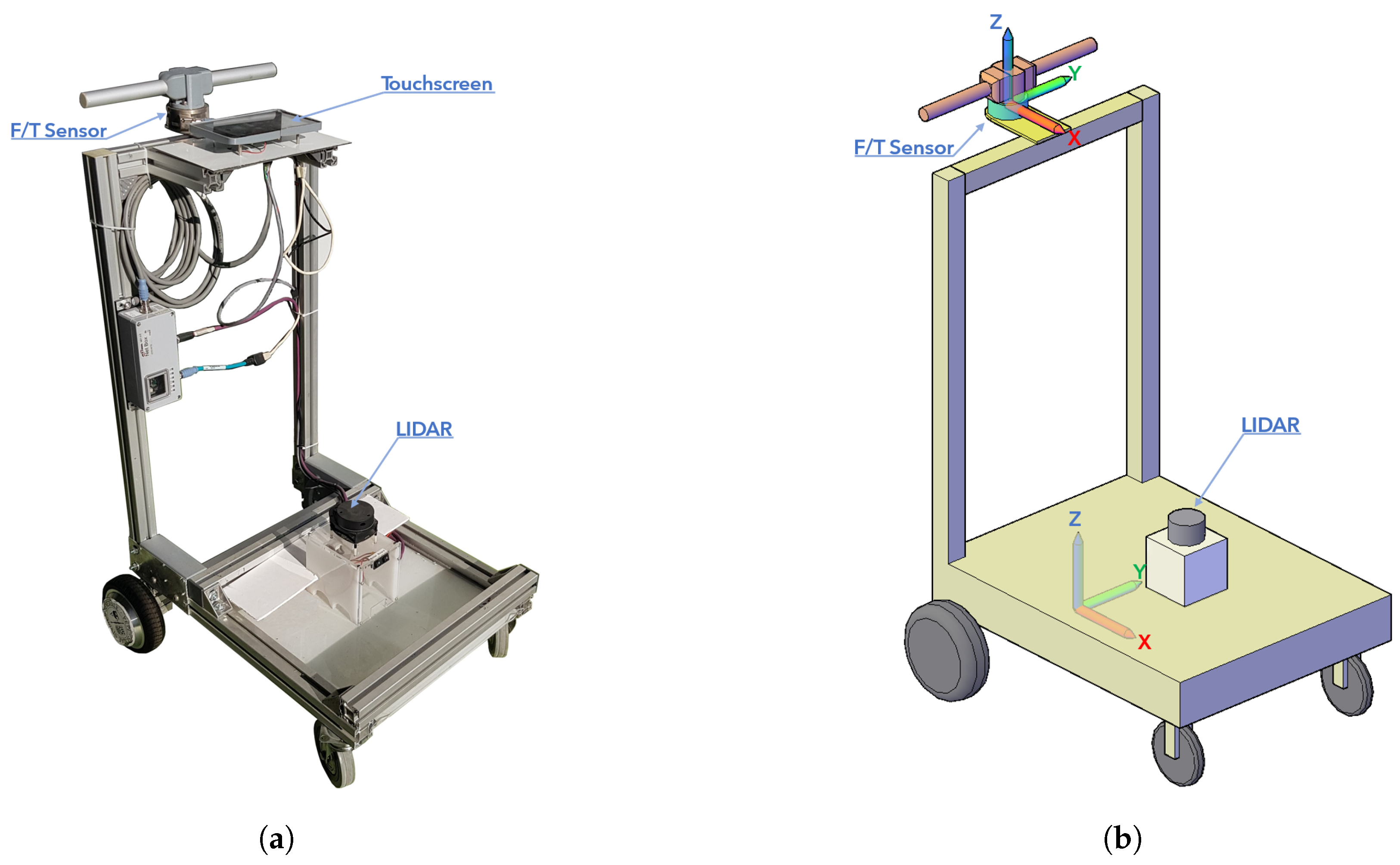
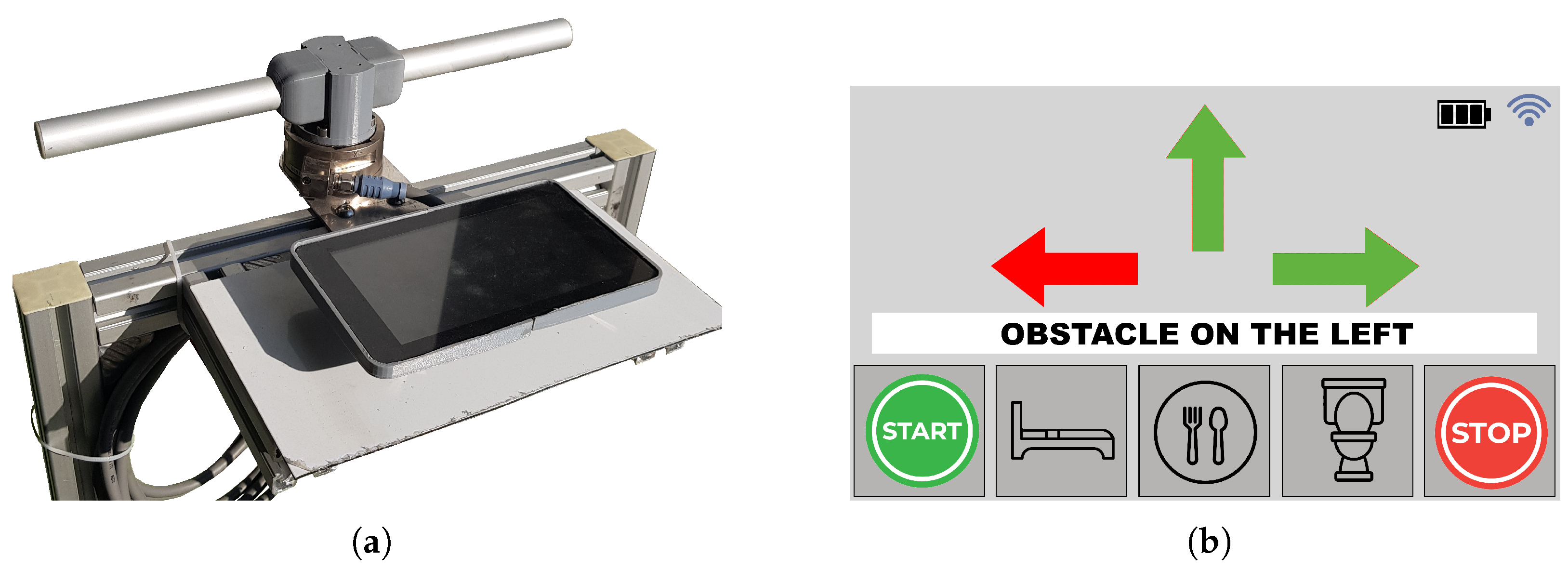
4], which has been enhanced and improved to serve as a model for future developments. The walker, shown in
Figure 1a, is a robust platform with two passive castor wheels at the front and two drive wheels at the rear, firmly attached to a robust frame made of commercial aluminum bars. The drive system consists of two motor-in-wheels in a differential configuration. This ensures optimal maneuverability and precise control, making it ideal for moving in tight spaces. The design of our modular and customizable walker may not be as polished as that of commercial models, as it is a laboratory prototype undergoing continuous development. It is designed with larger dimensions to ensure that there is enough space for all current and future components. The adaptable frame provides essential flexibility for a lab platform engaged in ongoing experimentation and enhancements. The prototype is 0.6 × 0.65 m, and the maximum height is 1.16 m from the ground and corresponds with the handlebar, as illustrated in
Figure 1. The structure allows the adjustment of the handlebar height to the patient. Several specs of the prototype are reported in the
Table 1.
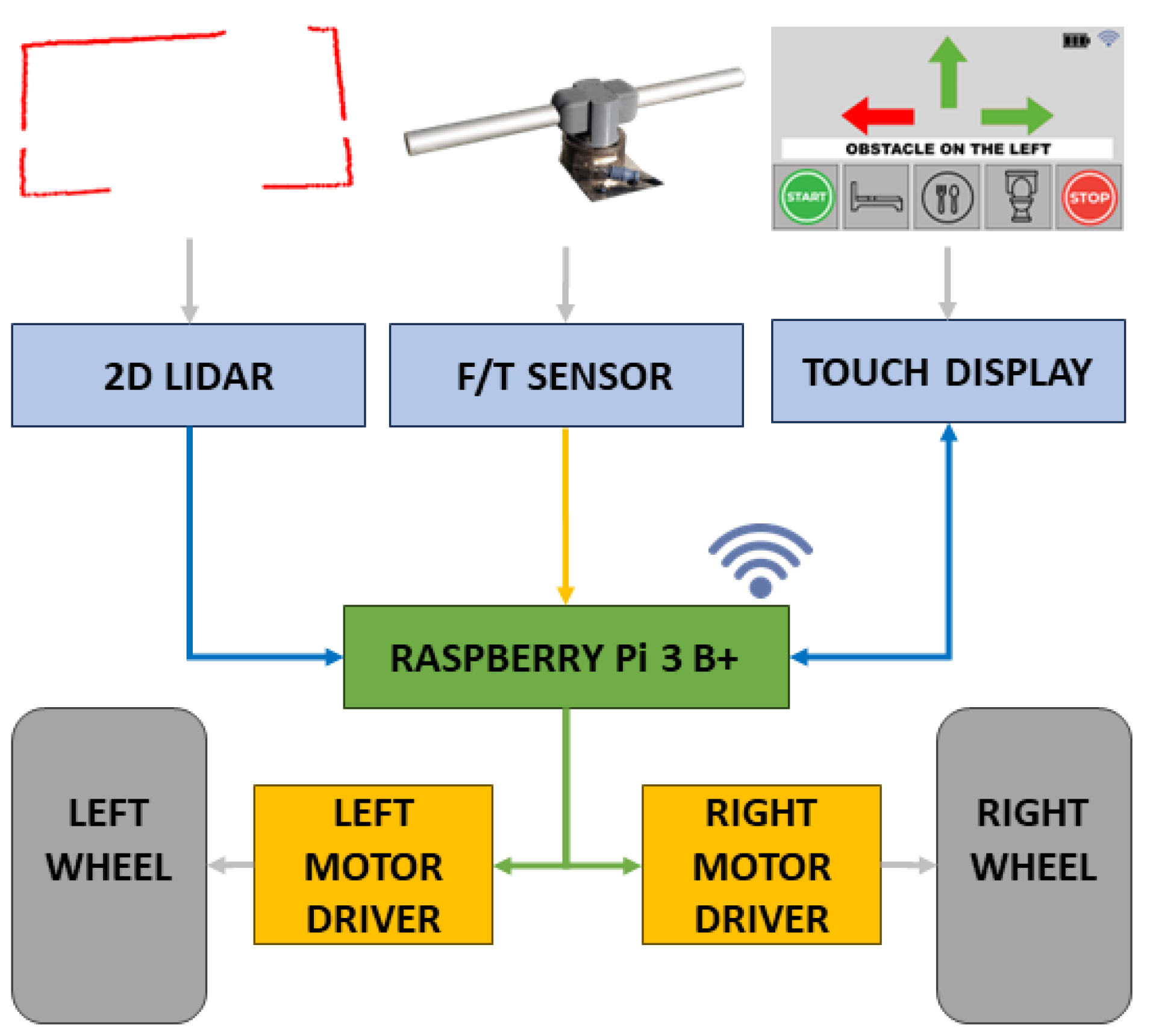
The smart walker utilizes Raspberry Pi 3 Model B+ as its main computing unit and runs the Robot Operating System (ROS) framework [
15]. Created to provide a common standard for robots, ROS offers a modular architecture that simplifies the design and development of complex robotic applications. Its flexibility makes it suitable for various robots, from drones to industrial robots. ROS provides a wide range of libraries, tools, and resources to help developers handle tasks such as perception, motion planning, and control. ROS middleware processes all input data, which are then used to execute the walker’s motion. Raspberry Pi communicates directly with the motor drive board through serial communication, allowing it to control both wheels.
Figure 2 shows the hardware used and the different types of connections indicated by the different colors.
To ensure operational safety, the platform features a dual emergency stop mechanism that combines both hardware and software components. The hardware-based stop is achieved through an external remote control, which enables the immediate interruption of the motor power supply, ensuring manual intervention capability during testing phases. The software-level emergency stop is implemented by continuously monitoring the data streams from the LIDAR and the force/torque (F/T) sensor. If either sensor fails to detect the user’s presence, either due to loss of signal or deviation from expected thresholds, the control system triggers an immediate cutoff of the power supply to the motors. This redundancy enhances the system’s robustness and ensures fail-safe behavior in the event of unexpected conditions.
Our proposal for a smart walker stands out due to its innovative shared control approach. An innovative navigation approach considers the user’s behavior and the surrounding environment. Using sensors with a long measuring range significantly improves obstacle perception. Our approach is rooted in deeply studying and understanding user needs and how people interact with their surroundings. These features make the proposed smart walker a significant technological advancement.
3.2. Sensing and Actuation
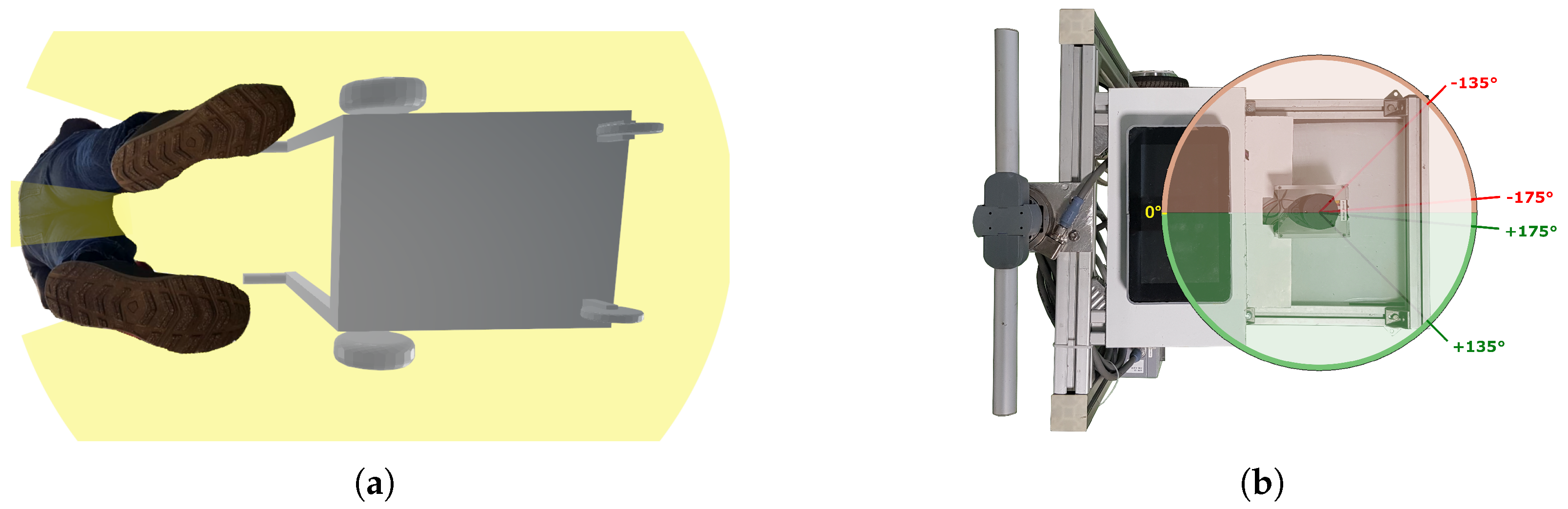
The RP LIDAR A1, by Slamtec, is a low-cost 2D laser sensor mounted on a platform. It can acquire 360 data points per rotation at 5.5 Hz, with a 6 m radius of the surrounding acquisition. This sensor provides information about the environment in which it is used. A rotating laser beam creates a 2D map of the surrounding space, including any obstacles detected within its operating range at the sensor height. The sensor also monitors the user’s stride and the distance between the walker, as depicted in
Figure 3a. This figure demonstrates how LIDAR technology can provide insights regarding the user’s presence by tracking the position of their legs. The analysis of leg positioning provides valuable information regarding the user’s orientation and enables the effective assessment of their intentions. According to
Figure 3b, the heading angle is the angle from the laser scanner to the obstacle. The human body can be divided into two halves along the sagittal plane. Similarly, the sensor data obtained from the LIDAR can also be divided into positive and negative ranges, with 0° representing the back position and 179° representing the front position on either side of the sensor. The platform is specifically designed for indoor applications, thereby mitigating challenges associated with ground variations. In such environments, the primary ground variation encountered is stairs, which the platform is not equipped to traverse. The LIDAR sensor is strategically positioned at a height that facilitates the detection of typical household obstacles, including chairs, tables, plants, walls, and doors. However, lower obstacles were excluded to ensure that the patient’s walking experience remains manageable. The experiments utilized common household objects, such as chairs, tables, and boxes of varying sizes, as obstacles. Although employing real objects would enhance the realism of the scenarios, the use of boxes permitted greater control and reproducibility in the laboratory settings. The LIDAR system is proficient in detecting obstacles of various sizes within designated categories. The redundancy provided by multiple laser acquisitions enhances the system’s ability to perceive objects accurately.
The walker handlebar is proposed as a solution to the challenge of driving the platform by understanding the user’s intent. The handlebar serves as a mechanism to facilitate the user’s control of the platform while simultaneously providing insight into their intended movements. This device can potentially revolutionize the platform’s usability, enhancing the user experience and promoting greater ease of use. The ATI Multi-Axis Gamma force–torque sensor is rigidly fixed between the walker frame and the handlebar, as illustrated in
Figure 4a. The sensor measures the six-dimensional wrench vector representation of forces and torques in the sensor’s reference frame shown in
Figure 1b, namely
. Through the force–torque sensor, the walker senses the user’s intent as the pressure is applied to the handlebar. The proposed method allows the walker to be easily maneuvered by the users through natural gestures. Currently, a commercial force–torque sensor is used to characterize the specifications required by the considered application. These specifications can eventually be exploited to develop a customized and low-cost device, as reported by [
16].
3.3. Assistive Mode
Shared control is paramount for ensuring seamless and secure navigation. The approach leverages an algorithm to integrate data from LIDAR and the handlebar, continuously monitoring the environment for potential obstacles. When obstacles are detected in the route, the system guides the user to avoid them by controlling the walker, ensuring smooth movement. Autonomous navigation and obstacle avoidance have been previously introduced in [
4].
The strategy prioritizes safety while simultaneously fostering user confidence and independence. By dynamically adjusting speed and direction based on real-time environmental acquisitions, the walker provides adaptive navigation solutions tailored to diverse scenarios. A six-axis sensor fixed below the handlebar translates the user intentions into actionable commands for the walker’s autonomous system. The strategic positioning of the handlebar ensures that the system accurately detects the user’s intentions, free from the interference typically caused by the pressure applied when using a traditional walker for support. This prototype is designed to assist users in navigation and enhance their spatial perception significantly.
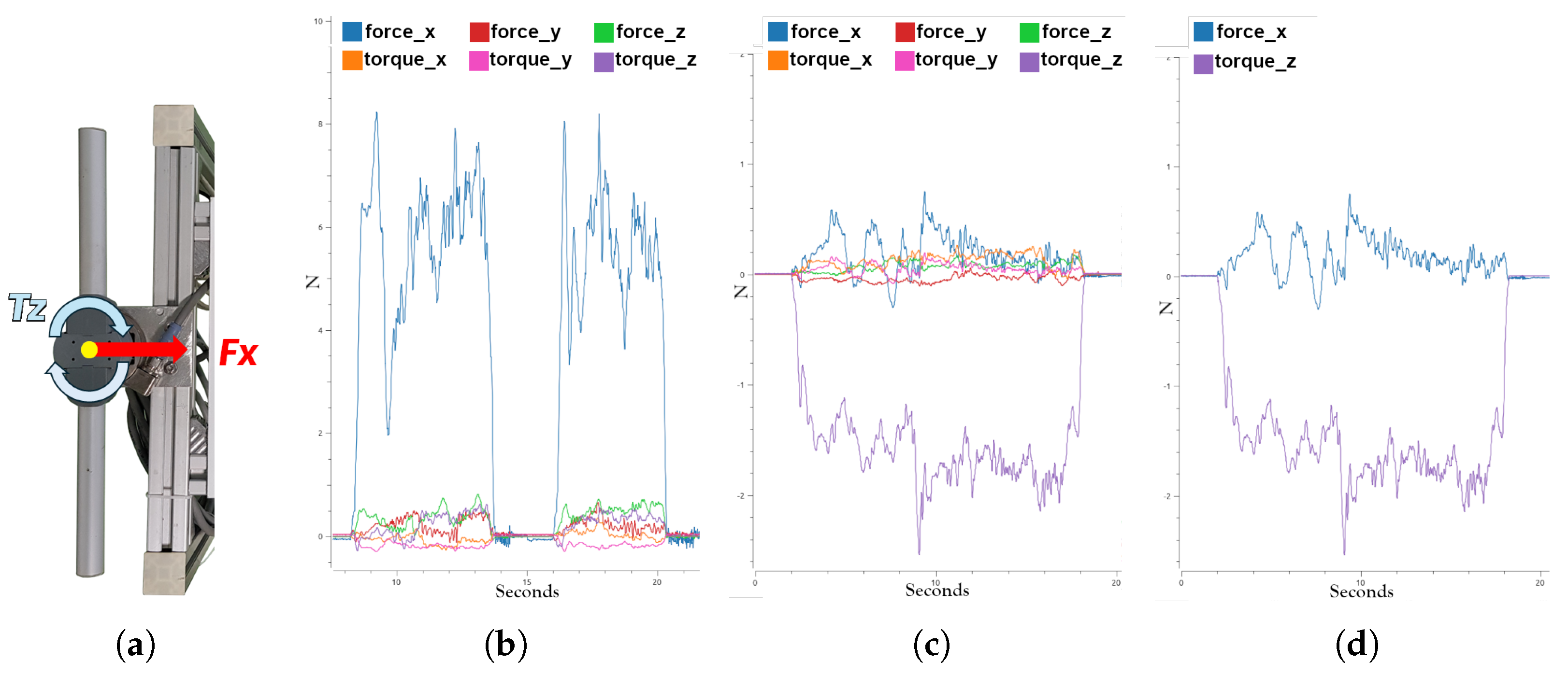
Through the force and torque readings along the three axes provided by the sensor (F
x, F
y, F
z, T
x, T
y, and T
z), the system demonstrates that not all input force–torque components are necessary to understand the user’s intentions. The F
x and T
z components, as shown in
Figure 5a, represent the only two components of the wrench vector that are crucial for detecting the user’s potential movements, such as moving forward, turning right, turning left, and stopping.
Figure 5 provides comprehensive insight into the data acquisition process carried out by the sensor, and it illustrates two test scenarios featuring data obtained from the force–torque sensor. A detailed analysis of this figure reveals how the sensor captures different component values based on the route. Both tests cover a distance of six meters and represent two typical phases in the daily use of a patient walker.
Figure 5b,c plot all of the six components provided by the force–torque sensor during two different scenarios. In the first scenario, the user pushes and releases the walker twice by the handlebar, with F
x being the most significant signal indicating forward movement. T
z, as shown in
Figure 5c, is used to understand the user’s intention to turn.
Figure 5d simplifies
Figure 5c by plotting only the two relevant components. This plot depicts a single turn on one side of the walker, showing both F
x and T
z components. These components indicate that the user applies torque to the handlebar for turning while simultaneously pushing forward. This is necessary as the scenario simulates a turn rather than a stationary rotation.
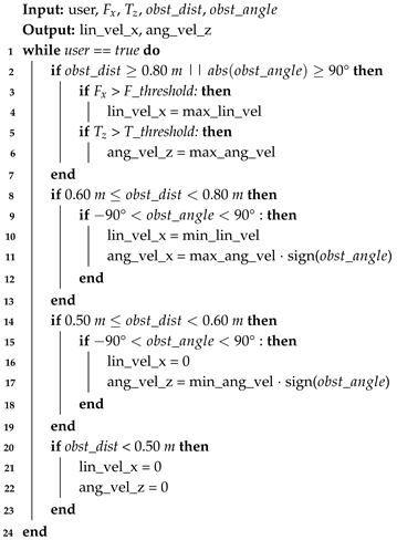
Figure 3b illustrates the LIDAR configuration, where each ray represents a single beam within a 360° range. This setup enables the detection of an obstacle’s position, allowing the platform to avoid it effectively. For instance, if the obstacle is on the right side, the platform rotates to the left, and vice versa, ensuring collision avoidance. When obstacles are present but unseen by the user, the walker guides the user safely around the obstacle. This obstacle avoidance and shared control are executed according to Algorithm 1. The algorithm utilizes data from LIDAR and force–torque sensors on the handlebars to monitor the user’s presence and constantly evaluates the distance and angle of surrounding obstacles. This allows the robot to avoid collisions and navigate safely through the environment. During the decision-making phase, the platform combines the obstacle’s position with the available maneuver space to execute the appropriate action. The algorithm uses these data to adjust the robot’s linear and angular speed, allowing it to adapt to various situations. As the distance between the object and the platform changes, the algorithm modifies its behavior accordingly to ensure safe navigation.
| Algorithm 1: Shared control algorithm |
![Actuators 14 00224 i001]() |
4. Experimental Results
The members of our research group conducted the experiments in compliance with the Declaration of Helsinki. Each member has been informed about the purpose of the tests and the data collected. Volunteers can request access to their data for verification or cancellation at any time.
The current experimental results were obtained from tests conducted with a limited number of users to validate the platform’s feasibility. To better understand the acceptance and experience of elderly individuals and those with mobility impairments, it is necessary to conduct a larger number of user surveys or usability tests.
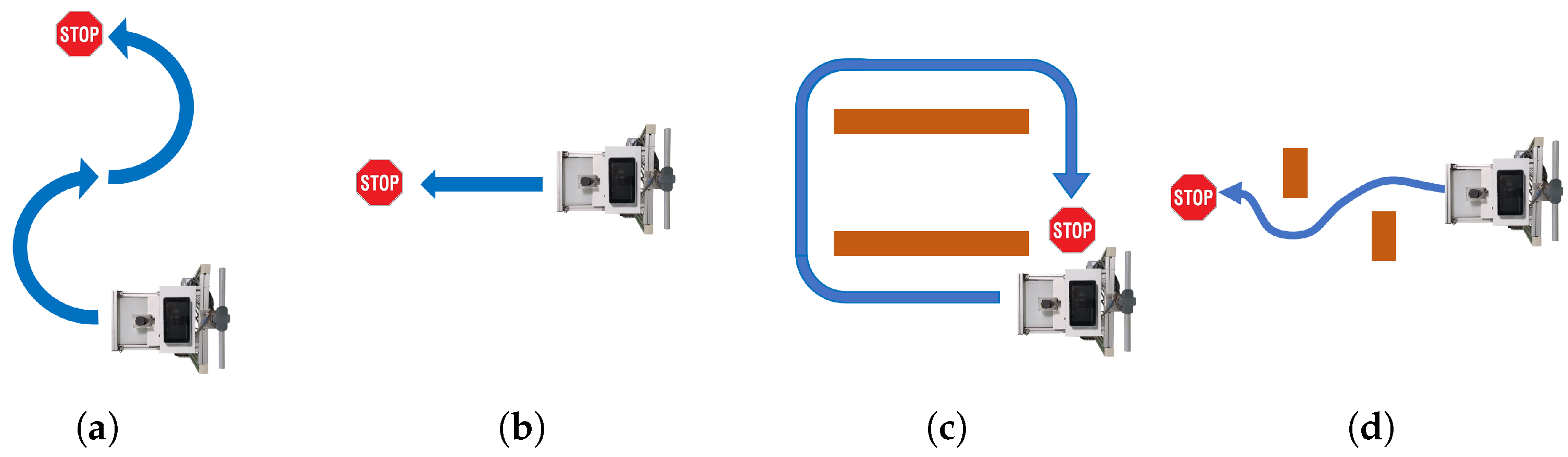
Each volunteer was provided with essential information about operating the walker and a general outline of the tests to be conducted across four different scenarios. The proposed scenario illustrates a standard hospital environment in which a patient navigates a corridor to reach a specific area on the same floor. Transitioning to a different floor, stairs, or a single step is not included in this scenario due to safety considerations. The detailed data collection methods and specific metrics were deliberately withheld to ensure that the participants’ behavior remained natural and unaffected during the trials. The scenarios are as follows:
Scenario 1: Turn right and then turn left;
Scenario 2: Alternate forward moves and stopping;
Scenario 3: Go straight and then immediately turn;
Scenario 4: Move forward and avoid the next two obstacles.
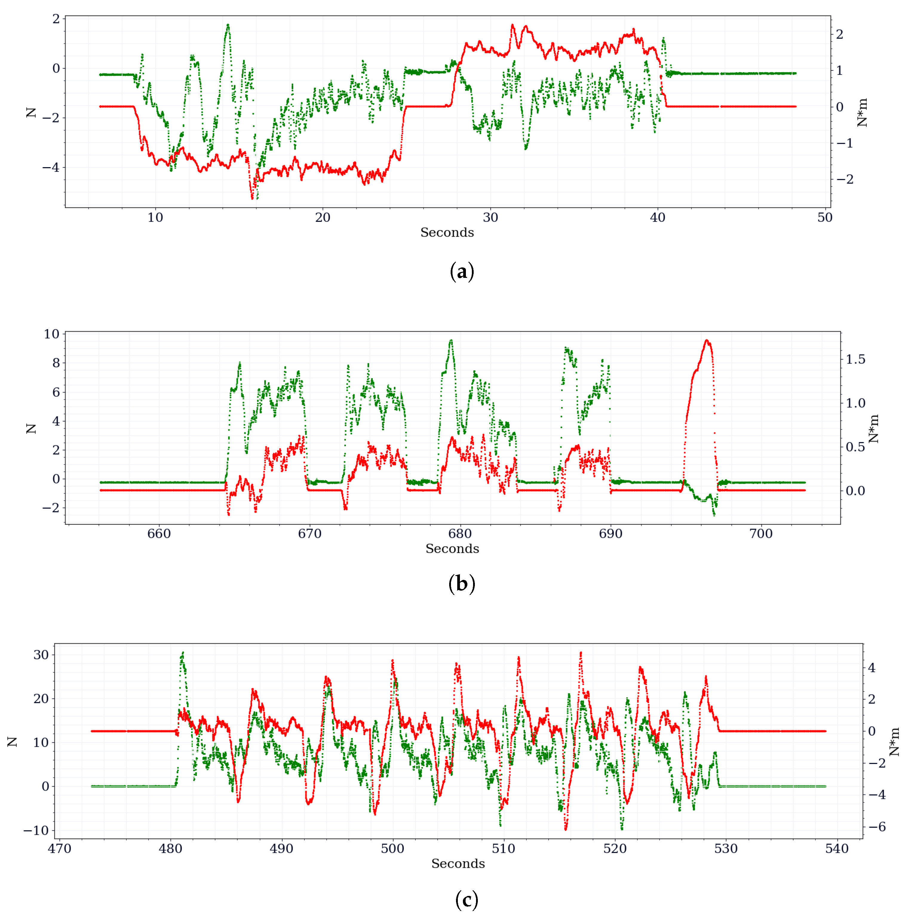
In scenario 1, volunteers begin by rotating clockwise for 10–15 s and then counterclockwise for the same duration. Users impart torque on the handlebars, which allows the system to process the patient’s intent to rotate. The test is shown in
Figure 6a, according to
Figure 7a in which it is possible to observe the data captured by the force–torque sensor.
For Scenario 2, volunteers move one meter forward, stop in place, and release the handler. The previous routine was repeated several times. The device tracks the intermittent force with which the users push and release the handlebars while maintaining an acceptable distance from the walker, as illustrated in
Figure 7b.
Figure 6b shows the proposed test.
Scenario 3 involves volunteers going straight and executing a swift 90-degree turn. The procedure is repeated multiple times within a clearly defined square area. The test is visually depicted in
Figure 6c, providing a better understanding of the exercise. The data acquired are shown in
Figure 6c.
In Scenario 4, volunteers face the toughest challenge: moving forward while avoiding two obstacles.
Figure 6d depicts the test to understand users’ path to reach the final point. The rotation to avoid the obstacle was left free to the volunteer, but everyone followed the same path.
This study emphasizes the importance of assisting users in avoiding collisions rather than adhering to predefined trajectories. It entails the identification of specific starting and ending points while continuously monitoring user movement. It is important to note that employing a ground truth approach would not facilitate the data export necessary for evaluating the proposed system. The experimental data reported in this paper are related to Scenario 4 because it represents more realistic human movement than previous random scenarios. The results of other tests conducted by volunteers are excluded from the discussion, as they exhibited notable similarities to the data presented herein.
Figure 7 and
Figure 8 are presented in a manner such that one signal corresponds to one axle, while the other signal corresponds to the alternative axle. This configuration facilitates the simultaneous plotting of both signals, thereby optimizing space utilization and ensuring temporal synchronization between the signals.
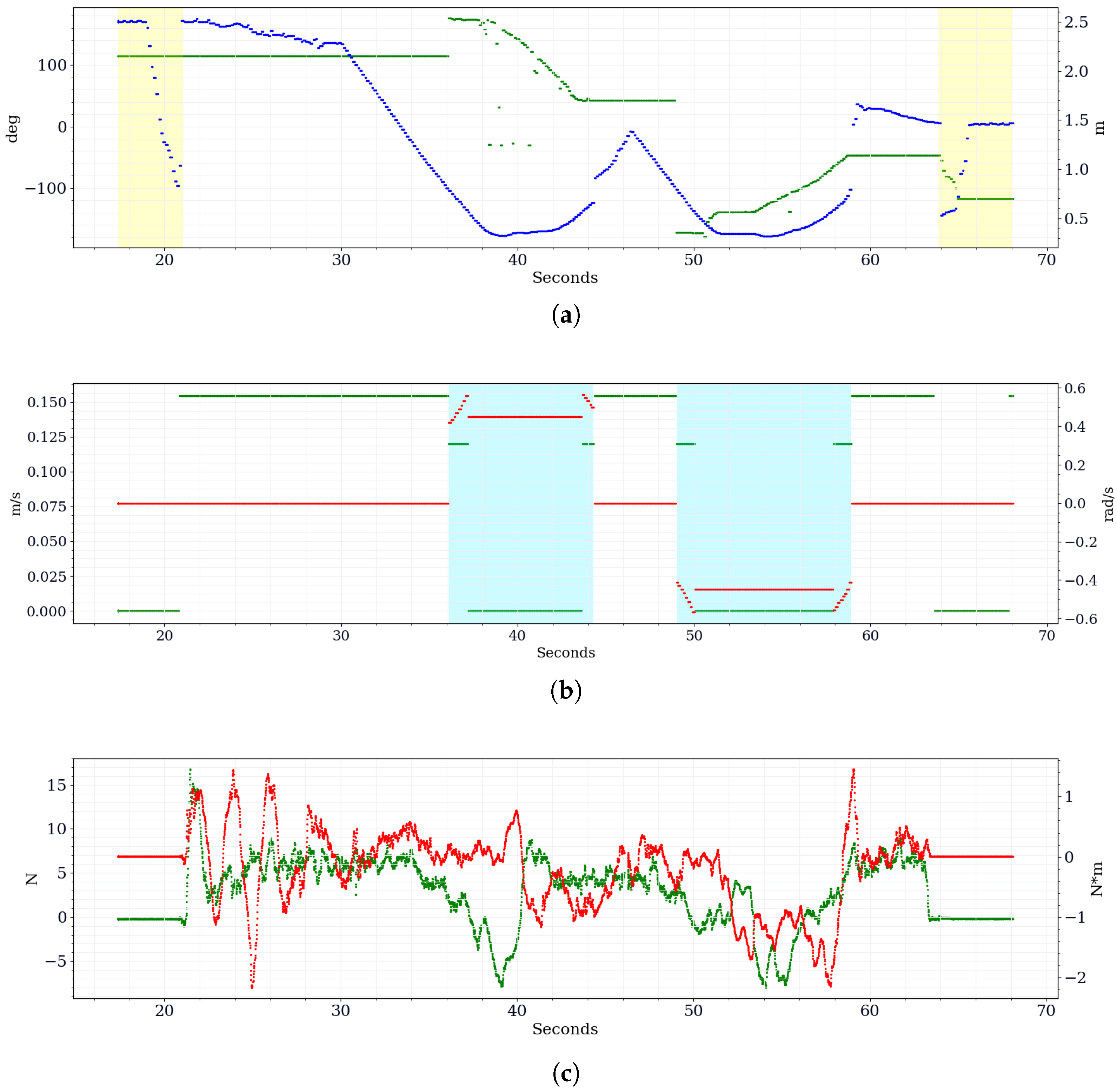
Figure 8 shows the three graphs of the data obtained during the trial aligned along the temporal axis. The top graph (
Figure 8a) shows the distance and the heading angle between the walker and the closest obstacle detected by the 2D LIDAR. The yellow overlay indicates when the user is close to the walker but above the activation threshold. Specifically, the control software determines that the user wants to use the walker if they are within a 90 cm threshold.
It is worth noting that the highlighted portions in
Figure 8a start with decreasing or increasing distance values over time, representing the user approaching or leaving the smart walker. However, once the user is within the distance activation threshold, they are no longer detected by LIDAR, as laser scan readings are properly filtered by considering the user’s position concerning the LIDAR itself and the walker.
In
Figure 8b, the computed linear and angular velocities are plotted. The green points represent the linear speed and reach the maximum value of 0.155 m/s without obstacles. The areas highlighted in cyan represent the phases in which the walker activates autonomous obstacle avoidance to help and guide the user in overcoming the obstacle. During the autonomous maneuver, the linear speed is reduced in the initial and final stages, while it is forced to zero in the central part when the platform is rotating in place. Still, in
Figure 8b, the red points represent the angular speed, which assumes opposite values over time, i.e., clockwise (CW) or counterclockwise (CCW) rotations, depending on the side the obstacles are detected along the path.
Figure 8c shows the values that the force–torque sensor acquires when the user touches the handlebar fixed on it. The X-axis detects the handlebar’s linear push, corresponding to the pressure of the user who wants to start a forward movement. This is indicated by the green points in
Figure 8c and is exploited by the control algorithm to translate the user’s will into linear velocity commands. The Z-axis torque is used to identify the direction that the user intends to take. Both hands impart rotations on the handlebar, which are sensed as a moment on the sensor and translated as angular velocity commands to the platform.
Finally, even if the user is within the activation threshold, a force must be applied on the handlebar so that the walker can elaborate the user’s will and compute the desired linear and angular speed. Otherwise, the velocity commands are set to zero. Such a situation can be observed from
Figure 8b at around 63 s, slightly before the yellow overlay starting at 64 s in
Figure 8a, when the user no longer touches the handlebar, as can be noticed by the null force and torque values in
Figure 8c, but it remains within the operating threshold. On the other hand, in correspondence with the yellow overlays, the speed is forced to zero because the activation check is not passed, as seen in
Figure 8b.


