Article

Speed Sensorless Motion Control Scheme for a Robotic Manipulator Under External Forces and Payload Changes

Facultad de Ingeniería, Universidad Autónoma del Carmen, Av. Central S/N & Fracc. Mundo Maya, Ciudad del Carmen C.P. 24115, Campeche, Mexico
*
Author to whom correspondence should be addressed.
Actuators 2025, 14(5), 209; https://doi.org/10.3390/act14050209
Submission received: 20 March 2025 / Revised: 17 April 2025 / Accepted: 23 April 2025 / Published: 24 April 2025
(This article belongs to the Section Control Systems)

Abstract

:
This paper proposes the design of a speed sensorless robust discontinuous controller for the trajectory tracking problem of a 5-DOF robotic manipulator under payload changes and torque disturbances in the joints. The developed observer-based controller is capable of performing trajectory tracking, ensuring stability, fast error convergence and speed sensorless operation. In order to avoid joint speed measurement, an estimation scheme based on a differentiation algorithm is implemented to estimate it. Simulation tests developed in MATLAB/Simulink are presented to show the high performance of the proposed scheme for two different trajectories with the model of the CRS Catalyst-5 by Thermo Electron®, Burlington, ON, Canada.

1. Introduction

Trajectory tracking for industrial robotic manipulators requires high-speed, high-accuracy movements to improve productivity and product quality. Controllers must account for factors like the robot mass, inertia, friction and model uncertainties to ensure smooth operation. External factors such as the sensor resolution, actuator quality and disturbances in areas like link masses, payloads and joint torques must also be considered, as neglecting them can impact system performance and stability [1].
A wide range of control techniques, from conventional schemes to advanced modern strategies, have been developed to address these challenges and ensure efficient operation. Conventional control schemes such as PID controllers have demonstrated good characteristics when operating with robotic manipulator systems. However, they have certain limitations when working in systems containing strong nonlinearities or under unknown external disturbances and noise. Additionally, such techniques’ operating ranges are often limited to a linearized region of the system. Another drawback is the lack of robustness when the system presents uncertainties in the model [2]. These limitations highlight the need for more robust and efficient control systems for robotic manipulators under disturbance and uncertainty conditions, leading to the development and application of modern control techniques.
One approach to address model uncertainties or the absence of a model is through fuzzy logic control, but it requires extensive knowledge of the system and may struggle with significant uncertainty or disturbances [3,4]. To improve the performance, hybrid approaches combining fuzzy logic with adaptive and robust control have been proposed, offering stable tracking despite uncertainties and disturbances [5,6,7]. However, these methods often overlook disturbances in joint torques. Neural network-based controllers, such as recurrent neural networks (RNNs), offer another model-free approach to estimating robotic manipulator parameters, with promising results in trajectory tracking under external disturbances [8,9,10]. However, these techniques have the disadvantage of requiring large training datasets, long computation times and large amounts of computational resources, which can limit their practical deployment in real-time control systems.
On the other hand, for cases when a mathematical model is available, several studies have explored model-based techniques as alternatives to achieve trajectory tracking in robotic systems. In [11], model predictive control (MPC) was applied to trajectory tracking in mobile robots, yielding good results. However, MPC requires a highly accurate model and has the disadvantage of using more powerful microprocessors, which can increase the total cost. Additionally, it is sensitive to uncertainties in the model parameters. In contrast, control schemes using discontinuous actions, like sliding mode (SM) control, are less sensitive to disturbances. For example, SM was used to stabilize a non-inertial inverted pendulum in [12], and several robotic manipulator applications employing SM controllers can be found in [13,14,15]. However, these methods often overlook disturbances in joint torques. The super-twisting (ST) algorithm, another robust discontinuous control approach, has been applied for trajectory tracking in [16,17,18]. While it incorporates robust control and accounts for some external disturbances, it does not address joint torque disturbances combined with payload variations, thus not ensuring stability under such conditions.
When certain variables in a system’s model are unavailable or noisy, estimation techniques like numerical differentiation can be used [19]. However, numerical differentiation can be imprecise at high speeds due to sampling frequency limitations. High-pass filters provide better estimates but produce “dirty derivatives”, while high-gain observers are sensitive to high-frequency noise and can cause infinite overshoot during transients [20,21]. Observers based on a mathematical model may provide good estimates, but their effectiveness depends on the model’s constraints, and they may not ensure finite-time convergence. Sliding mode differentiators, however, guarantee finite-time convergence [22], reduce overshoot with proper gain selection and are effective in noisy or disturbed environments, without requiring heavy computation [23,24].
To enhance the robustness and efficiency of controllers under the influence of uncertainties and perturbations, various control schemes based on estimations have been proposed [25,26]. For instance, ref. [27] presents a nonlinear functional observer to estimate joint velocities, considering model uncertainties and external disturbances. Similarly, ref. [28] presents a control scheme for a flexible manipulator to reduce vibrations and disturbances while tracking trajectories. One widely used approach for robotic manipulators is disturbance observer (DO)-based control, which focuses on estimating unknown disturbances affecting the manipulator, allowing the controller to compensate for them [29]. However, DO-based controllers require an accurate dynamic model of the system; inaccuracies in parameters such as inertia, friction, payload or common phenomena like saturation and noise can significantly degrade the observer’s performance [30,31]. Furthermore, DO schemes only estimate disturbances and not system states, which limits their application in sensorless operation schemes. To address this limitation, extended state observer (ESO)-based controllers have been proposed as an alternative. These controllers can estimate both disturbances and system states, assuming at least some knowledge of the system model [32]. However, the performance of ESO-based schemes depends heavily on the selection of appropriate observer bandwidths and nonlinear gains, which can be non-intuitive and system-specific. Poor tuning may lead to sensitivity to noise, necessitating additional filtering [33]. Therefore, the use of a differentiator arises as an alternative for sensorless operation even when noise is present, which can enhance systems’ robustness.
This paper proposes the design of a speed sensorless, discontinuous control scheme based on a differentiator for trajectory tracking in the task space of a robotic manipulator—specifically, the Thermo CRS Catalyst 5-DOF robot. The control task must be accomplished even when uncertainties exist, as well as bounded disturbances that affect the actuator’s performance, particularly those acting on the joint torques of the manipulator. The differentiator will be used to estimate the joint velocities, which allows the elimination of speed sensors and simple implementation, guaranteeing finite-time stability and precise estimations even in noisy environments, without requiring system model information. The discontinuous control scheme based on the ST algorithm makes use of such state estimations to operate properly under payload changes, joint disturbances and model uncertainties.
The following sections of this paper are organized as follows: Section 2 describes the mathematical model of the robotic manipulator; Section 3 describes the design of the control algorithm, as well as its corresponding stability test; Section 4 presents the results of this work when two different tracking trajectories are applied, with the purpose of verifying the tuning flexibility of the control algorithm, where the robot shows its inherent versatility in following various trajectories, representing different applications; and Section 5 describes the conclusions.

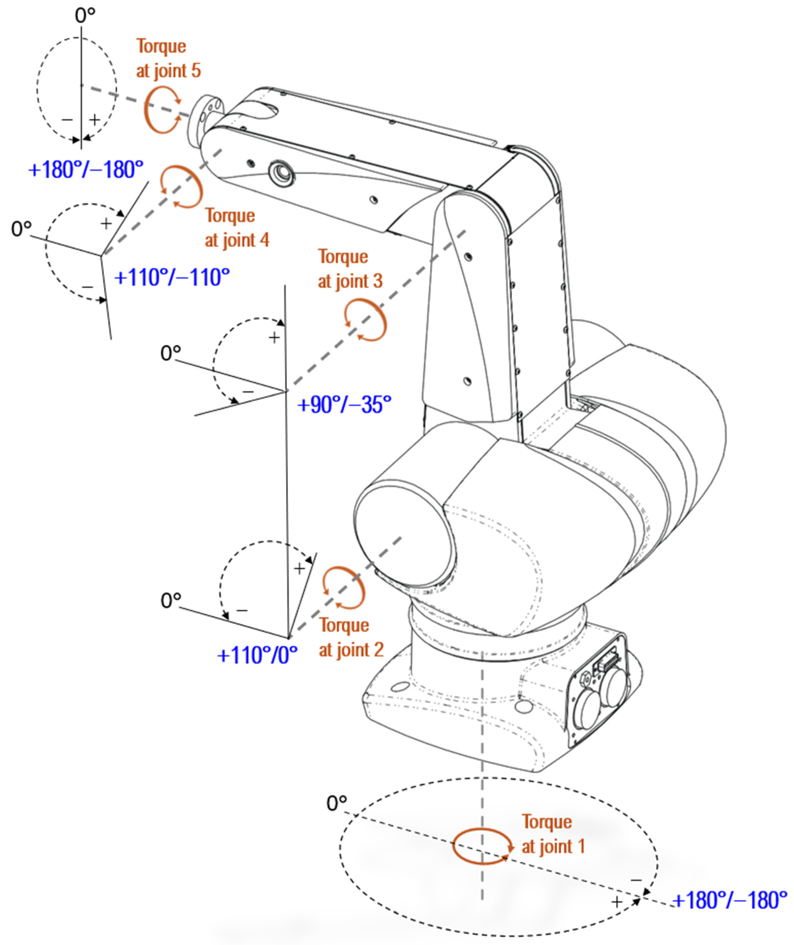
2. Mathematical Model: Thermo CRS Catalyst 5-DOF Manipulator Robot

The mathematical model of the 5-DOF manipulator robot is given by [34]
M i α ¨ + M c α ˙ + v g = τ t
where M i = f 1 α , m , I , l , l c ,   R 5 × 5 is a symmetric positive definite matrix of inertias; M c = f 2 α , α ˙ m , l , l c ,   R 5 × 5 is the matrix of centripetal and Coriolis torques; v g = f 3 ( α , g , m , l , l c , ) R 5 × 1 is the vector of gravitational torques; α R 5 × 1 is the state vector containing the positions of the joint angles; α ˙ R 5 × 1 is the velocity vector of the joints; α ¨ R 5 × 1 is the acceleration vector of the joints; τ ( t ) R 5 × 1 is the input torque vector applied to the joints; g is the gravity force constant; and I, l, lc, m are the parameters of the manipulator robot model, which represent the inertia of the link, the length of the link, the length of the axis to the center of mass and the mass of the link, respectively, and their values are indicated in Table 1.
Now, considering that there are bounded uncertainties in the masses of the links, which can be represented by M i u , M c u , v v g u , these will affect the matrices M i , M c and the vector v g , respectively. In addition, it is also considered that there is the presence of external and bounded disturbances in the force torques applied to the joints; thus, the mathematical model could be represented by
M i u α ¨ + M c u α ˙ + v g u + τ d = τ t
where M i u , M c u , v g u have the following structure: M i u = M i + M i u , M c u = M c + M c u , v g u = v g + v v g u . They represent, respectively, the inertia matrix, the Coriolis matrix and the gravitational force vector, which consider the effects caused by the uncertainties in the masses of the links. τ d represents the vector of external and bounded disturbances that are added to the input torque vector applied to the joints. Equation (2) can be expressed in state variables with the following state variable selection:
x 1 x 2 = α α ˙
This results in
x ˙ 1 x ˙ 2 = x 2 M i u 1 τ t τ d M c u x 2 v g u
The parameters of the Thermo CRS Catalyst 5-DOF robotic manipulator are established in Table 1; Figure 1 shows a drawing of this robot, highlighting its joint position range.

3. Problem Statement

The main problem lies in accurately tracking trajectories with fast response times, even in the presence of disturbances, without requiring speed measurements. While previous research has considered perturbations in the payload, it has largely overlooked the effects of force torques applied to the robot’s joints, together with speed sensorless operation. To address this gap, a control scheme is developed for the Thermo CRS Catalyst 5-DOF robotic manipulator. This scheme will enable the actuators to control the robotic arm such that it can perform rapid and precise movements, even under bounded disturbances affecting various parts of the manipulator, such as joint torques, as well as payload perturbations at the end effector, which directly influence the mass of the final link. The proposed approach combines a discontinuous control scheme with a state estimator based on a differentiator, as illustrated in Figure 2. This configuration takes advantage of the fact that the measurements of the variables will not depend entirely on the mathematical model but on the differentiator; at the same time, we take advantage of its effective characteristics when there is the presence of noise in the measurements.
The position and velocity of the joint angles can be estimated from the following two expressions arising from the sliding mode-based differentiation algorithm [24]:
α 0 ˙ ^ = λ 1 L α 0 ^ α s i g n α 0 ^ α + α 1 ˙ ^
α 1 ¨ ^ = λ 0   L   s i g n α 1 ˙ ^ α 0 ˙ ^
where α 0 ˙ ^ and α 1 ¨ ^ R 5 x 1 are the estimated velocity and acceleration, respectively, of the joint angles; λ 1 > 0 , λ 0 > 0 , are the gains to adjust the estimated variables; and L > 0 is a Lipschitz constant. The convergence for this differentiator to α 0 ˙ ^ = α is guaranteed if the function α has a derivative with Lipschitz constant L > 0 and the condition λ 0 > L is fulfilled, as shown in [22].
By integrating Equations (4) and (5), the estimated positions and velocities of the joint angles are obtained; thus, the corresponding tracking errors of the position and velocity can be obtained as follows:
e = α d α 0 ^ = x 1 d x ^ 1 0
e ˙ = α d ˙ α 1 ˙ ^ = x 2 d x ^ 2 1
where x 1 d ,   x 2 d represent the desired position and velocity vectors, and x ^ 1 0 ,   x ^ 2 1 are the estimated position and velocity vectors of the joint angles, respectively. Then, the position and velocity estimation errors can be expressed as
e x 1 = x 1 x ^ 1 0
e x 2 = x 2 x ^ 2 1
The law of the proposed discontinuous scheme based on the differentiator is stated as
τ t = M i u v S M C S T + e ˙ + α d ¨ + M c u α ˙ + v g u
where v S M C S T is the ST algorithm and is defined by [24]
v S M C S T = a   σ   s i g n σ b 0 t s i g n σ d σ ;     a > 0 ,   b > 0
where σ is the chosen sliding surface and is defined taking into consideration the position and velocity errors as follows:
σ e = c e + e ˙ ; c > 0
The objective of this algorithm is to force the error and the derivative of the error to the origin of the system represented by the model given in Equation (3). We obtain the derivative of Equation (12):
σ ˙ = c e ˙ + x ˙ 2 d M i u 1 τ t τ d M c u x 2 v g u
The stability of the proposed controller Equation (10) is based on the following positive definite function [16]:
V = 1 2 σ σ T
whose derivative can be expressed as
V ˙ = σ T c e ˙ + x ˙ 2 d M i u 1 τ t τ d M c u x 2 v g u
By substituting Equations (10) and (11) into Equation (15) and considering that σ = σ T s i g n σ , we obtain
V ˙ a σ 1 2 σ b 0 t σ d t
Therefore, Equation (16) ensures the stability of the discontinuous observer-based controller and the convergence of errors if the condition ( a + b > 0 ) is fulfilled.

4. Results and Discussion

This section presents the simulation results obtained using MATLAB® R2024a/Simulink version 24.1, (Natick, MA, USA) to test the proposed discontinuous control scheme based on the sliding mode differentiator. Two distinct trajectories in a three-dimensional task space were used to evaluate the controller’s performance. The first trajectory, a circular path, was chosen to demonstrate the proper operation of the control scheme in a relatively simple task. A more complex trajectory, in the form of a four-petal rose, was then used to assess the performance of the proposed approach in a more challenging scenario. Additionally, the results were compared with those of a disturbance observer (DO)-based controller, as proposed by Chen [35], which utilizes the widely used computed torque control (CTC) technique.
Figure 3 and Figure 4 show the ideal tracking trajectories. However, these trajectories are not suitable for direct implementation, as they do not consider the physical limitations specified by the robot manufacturer. Using them without modification could lead to mechanical overstress and trajectory-tracking overshoots [36]. Therefore, a modified reference trajectory was used for each of these trajectories, which considers the necessary physical constraints and ensures the safe operation of the robotic manipulator. The modified reference trajectory for the circumference is shown in Figure 5a.
The values of the control scheme parameters λ 1 , λ 0 and L , expressed in Equations (4) and (5) for the differentiator; the parameters a , b , expressed in Equation (9) for the control law; and the value of c, expressed in Equation (10) for the sliding surface, are indicated in Table 2 and Table 3. These are used for both trajectories.
The simulations represent the application of a robust discontinuous control scheme, as described in Section 3, for the trajectory tracking of the Thermo CRS Catalyst 5-DOF robotic manipulator. In these simulations, external bounded noise and disturbances affecting the torques of the first four joints were included. Additionally, the effects of unknown bounded changes in the payload were also considered.
(A)
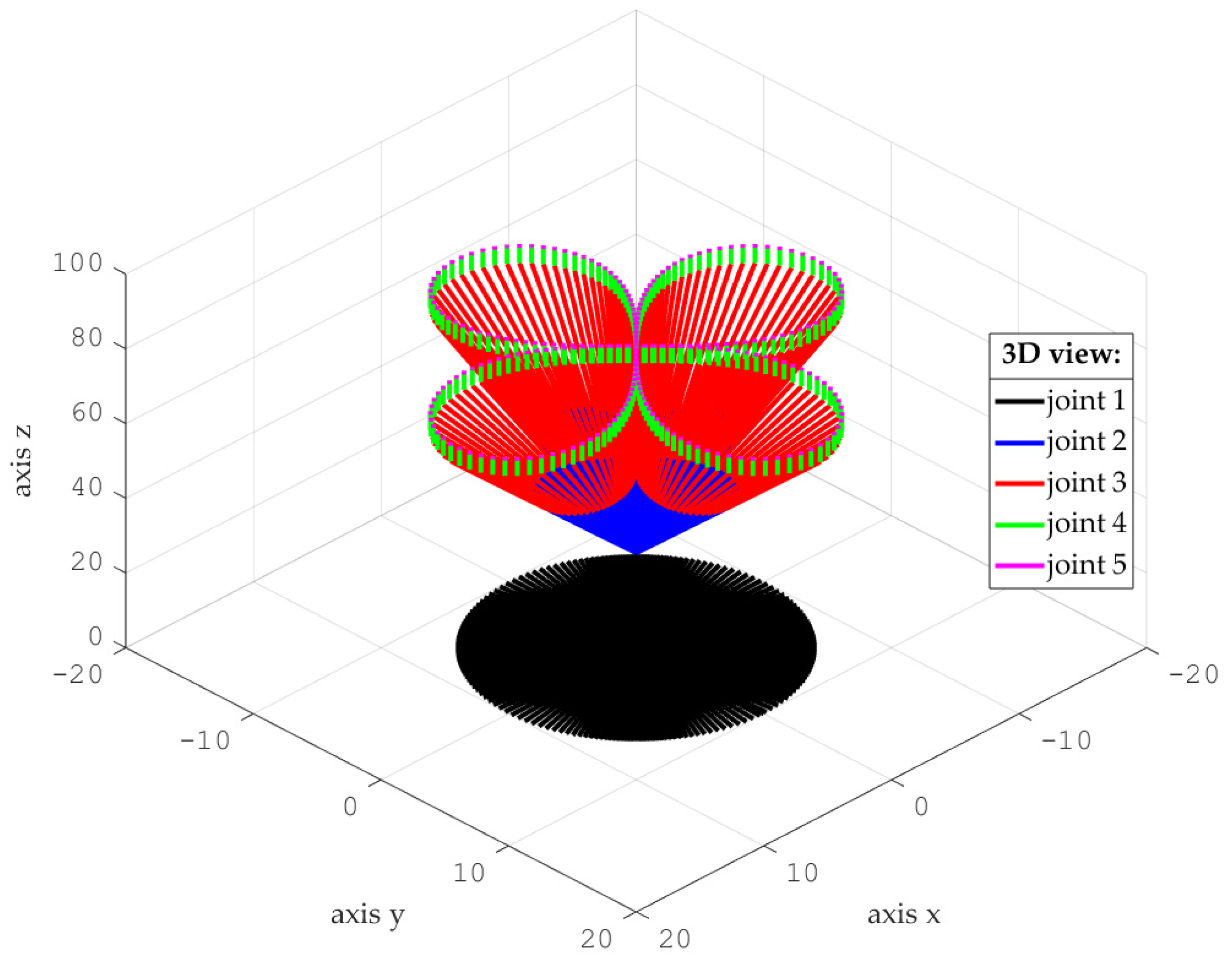
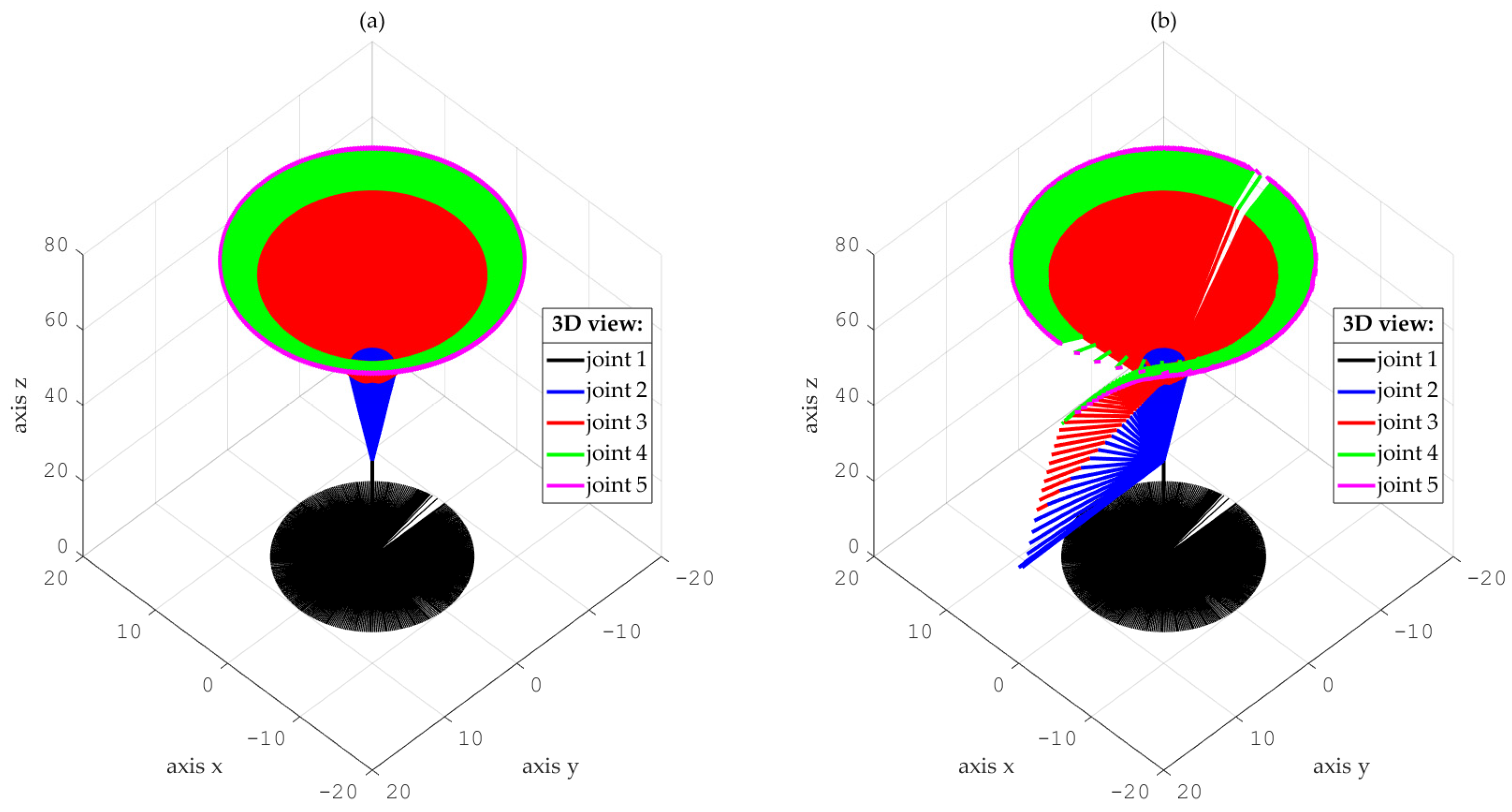
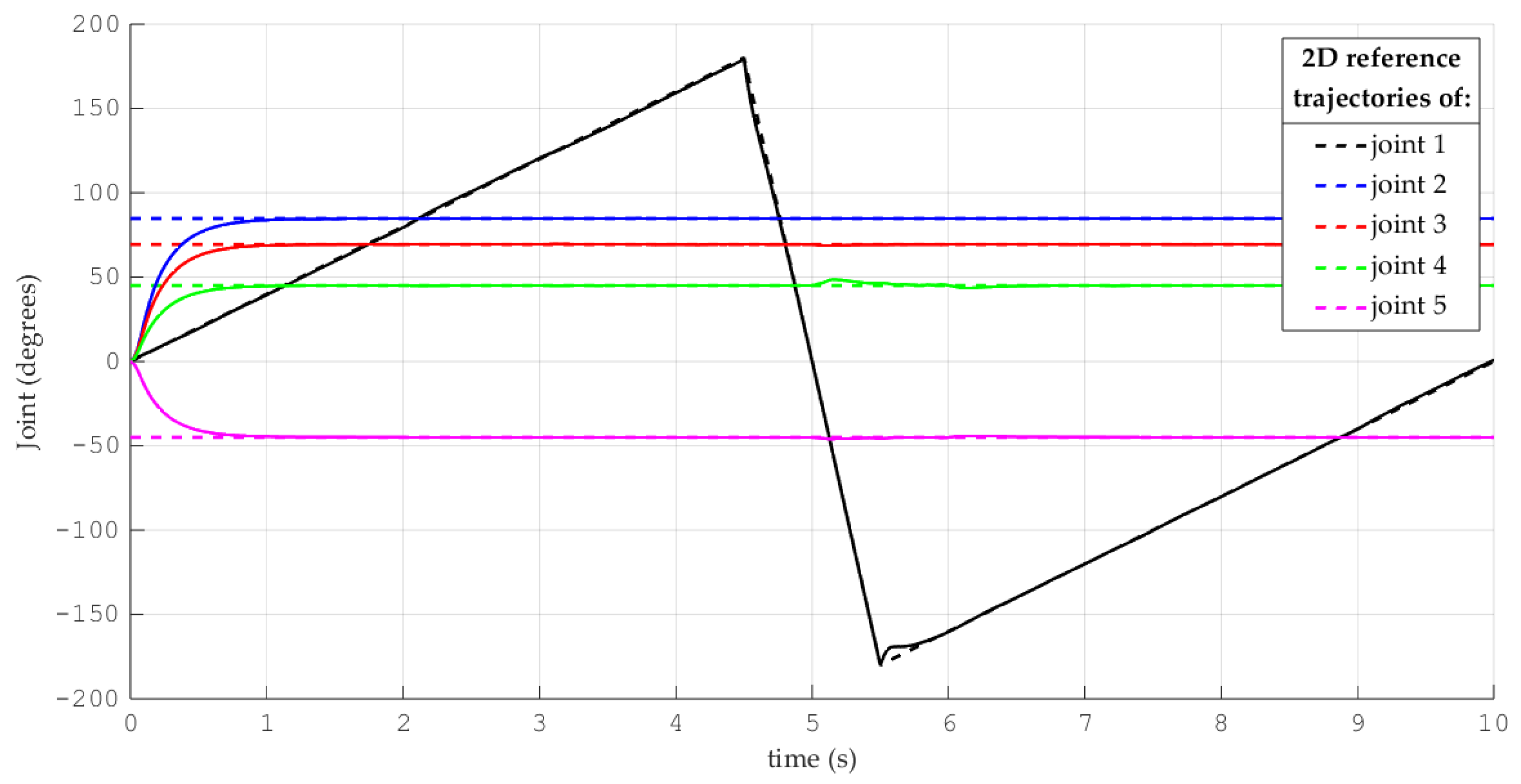
Simulations for the reference trajectory: circumference in three-dimensional space
Figure 5a shows the desired reference trajectory in 3D, and Figure 5b shows the resulting 3D tracking of the system for such a trajectory. It can be observed that the last joint movement corresponds to the desired circular trajectory.
The angles of the desired trajectory (segmented line) and the corresponding system tracking response (solid line) for each joint are depicted in Figure 6. After a duration of 1.25 s, the precise tracking of the reference trajectory is obtained for each one of the joints. It is also observed that there is a slight overshoot when joint 1 suddenly changes from a value of 180° to −180°, which is explained by the inherent link inertia.
To evaluate the performance of the system under payload changes, a sudden change in mass is considered in the last link of the robotic manipulator, as illustrated in Figure 7. The uncertainty is bounded by a maximum value of 1 kg because the manufacturer’s specifications allow working with a maximum payload of this value.
The external bounded disturbances that affect the torques of the first four joints of the robotic manipulator are shown in Figure 8. These types of disturbances represent sudden forces directly applied on the links, generating torques that modify the input torque vector.
Figure 9 shows the tracking errors in the joint angles for the circular trajectory. Although the system is permanently subject to disturbances, as seen in Figure 8, the trend of the errors towards zero can be observed, even when the reference that corresponds to joint 1 presents a sudden change in the time period of 4.5 to 5.5 s. This increase in the tracking error is related to the inertia generated by the strong and sudden changes in the angle of the reference signal for joint 1 and not to the external disturbances affecting the system.
On the other hand, Figure 10 and Figure 11 show the graphs of the position and speed estimation errors of the differentiator, respectively, where the convergence to the real value is verified.
(B)
Comparison of the performance of the proposed control scheme versus a disturbance observer-based control scheme
In order to verify the appropriate performance of the proposed controller, a comparison is performed against a DO-based control scheme, as presented in [35], which is based on a CTC scheme with the following form:
u t = M θ K p θ θ d + K v θ ˙ θ ˙ d θ ¨ d G θ , θ ˙
where G ( θ , θ ˙ ) contains the coupled disturbances, Coriolis forces and gravity forces, and the selected values for the gain matrices are
K p = d i a g ( 375   2375   2375   1375   1125 ) K v = d i a g ( 300   700   900   300   400 )
For such comparison, a test was developed for the trajectory shown in Figure 12a, describing a four-petal rose in 3D space. The uncertainty and disturbance conditions are the same as for the last case, which are depicted in Figure 7 and Figure 8. The tracking result of the proposed controller in a 3D view is depicted in Figure 12b, showing that, even when the trajectory is more complex, the scheme performs appropriately.
Figure 13 depicts the joint angles of the desired trajectory (segmented line) and the corresponding system response for both control schemes (solid line for the proposal and dotted line for ref. [35]), under the same disturbance conditions. After a period of 1.25 s, the precise tracking of the reference trajectory is obtained for each one of the joints with our sensorless proposal, while the reference scheme requires around 2 s. The joint angle tracking errors for both controllers (solid black line for our proposal and segmented blue line for ref. [35]) when following the trajectory of the four-petal rose are shown in Figure 14. It can be seen that, although the system is constantly subject to uncertainties and disturbances and the references are time-varying, the errors converge to a small region near zero.
Furthermore, the proposed control scheme shows the precise tracking of the desired joint angles even when aggressive changes in direction are present, as shown in the first joint from 3.7 s to 4.7 s. Table 4 presents the values of the integral absolute error (IAE) for every joint of the robot, which shows that the proposed observer-based scheme has smaller errors in almost every joint over the DO-based controller proposed by Chen, which indicates overall good performance. Such performance regarding the control signal force is obtained taking into account that the gain parameters of the proposed controller shown in Table 3 are lower than the DO-CTC in Equation (17).
The estimation errors are illustrated in Figure 15 and Figure 16, respectively. Similarly to the previous case, the errors are small enough, which confirms the ability of the differentiator to perform precise estimation regardless of the complexity of the selected trajectory.

5. Conclusions

This paper proposes a speed sensorless, robust, discontinuous differentiator-based control algorithm for the motion control of the Thermo CRS Catalyst 5-DOF robotic manipulator. The system achieved accurate and fast trajectory tracking in 3D space across all manipulator joints. The controller operated effectively without relying on speed measurements, even in the presence of bounded uncertainties in the end-effector payload and external torque disturbances affecting the first four joints. The performance of the proposed controller was evaluated and compared with a disturbance observer (DO)-based computed torque control (CTC) method, showing improved tracking accuracy, reflected in lower integral absolute error (IAE) values for nearly all joints, while requiring lower controller gains, highlighting its improved efficiency.

Author Contributions

Methodology, H.A.; Software, J.P.; Validation, D.C.-V.; Writing—original draft, J.P. and D.C.-V.; Writing—review & editing, D.C.-V. and H.A.; Supervision, H.A. All authors have read and agreed to the published version of the manuscript.

Funding

This research received no external funding.

Data Availability Statement

Data is contained within the article.

Conflicts of Interest

The authors declare no conflict of interest.

References

  1. Reboucas Filho, P.P.; da Silva, S.P.P.; Praxedes, V.N.; Hemanth, J.; de Albuquerque, V.H.C. Control of singularity trajectory tracking for robotic manipulator by genetic algorithms. J. Comput. Sci. 2019, 30, 55–64. [Google Scholar] [CrossRef]
  2. Božek, P.; Nikitin, Y. The Development of an Optimally-Tuned PID Control for the Actuator of a Transport Robot. Actuators 2021, 10, 195. [Google Scholar] [CrossRef]
  3. Yilmaz, B.M.; Tatlicioglu, E.; Savran, A.; Alci, M. Self-adjusting fuzzy logic based control of robot manipulators in task space. IEEE Trans. Ind. Electron. 2021, 69, 1620–1629. [Google Scholar] [CrossRef]
  4. Urrea, C.; Kern, J.; Alvarado, J. Design and evaluation of a new fuzzy control algorithm applied to a manipulator robot. Appl. Sci. 2020, 10, 7482. [Google Scholar] [CrossRef]
  5. Bae, H.J.; Jin, M.; Suh, J.; Lee, J.Y.; Chang, P.H.; Ahn, D.S. Control of robot manipulators using time-delay estimation and fuzzy logic systems. J. Electr. Eng. Technol. 2017, 12, 1271–1279. [Google Scholar] [CrossRef]
  6. Chang, W.; Li, Y.; Tong, S. Adaptive fuzzy backstepping tracking control for flexible robotic manipulator. IEEE/CAA J. Autom. Sin. 2018, 8, 1923–1930. [Google Scholar] [CrossRef]
  7. Djelal, N.; Saadia, N.; Ramdane-Cherif, A. Adaptive force-vision control of robot manipulator using sliding mode and fuzzy logic. Autom. Control Comput. Sci. 2019, 53, 203–213. [Google Scholar] [CrossRef]
  8. Huang, H.L.; Cheng, M.Y.; Huang, T.Y. A Rapid Base Parameter Physical Feasibility Test Algorithm for Industrial Robot Manipulator Identification Using a Recurrent Neural Network. IEEE Access 2023, 11, 145692–145705. [Google Scholar] [CrossRef]
  9. Li, T.; Zhang, G.; Zhang, T.; Pan, J. Adaptive neural network tracking control of robotic manipulators based on disturbance observer. Processes 2024, 12, 499. [Google Scholar] [CrossRef]
  10. Zhang, Z.; Zheng, L.; Yu, J.; Li, Y.; Yu, Z. Three recurrent neural networks and three numerical methods for solving a repetitive motion planning scheme of redundant robot manipulators. IEEE/ASME Trans. Mechatron. 2017, 22, 1423–1434. [Google Scholar] [CrossRef]
  11. Klančar, G.; Škrjanc, I. Tracking-error model-based predictive control for mobile robots in real time. Robot. Auton. Syst. 2007, 55, 460–469. [Google Scholar] [CrossRef]
  12. Trejo-Sosa, L.E.; Alazki, H. Control Robusto Adaptable para Sistema no inercial: Acrobot sobre un carro Robust Adaptive Control for System non-inertial: Acrobot on a cart. Diseño Innov. 2019, 3, 8–15. [Google Scholar] [CrossRef]
  13. Wang, Y.; Zhang, Z.; Li, C.; Buss, M. Adaptive incremental sliding mode control for a robot manipulator. Mechatronics 2022, 82, 102717. [Google Scholar] [CrossRef]
  14. Mobayen, S.; Mofid, O.; Din, S.U.; Bartoszewicz, A. Finite-Time Tracking Controller Design of Perturbed Robotic Manipulator Based on Adaptive Second Order Sliding Mode Control Method. IEEE Access 2021, 9, 71159–71169. [Google Scholar] [CrossRef]
  15. Truc, L.N.; Vu, L.A.; Thoan, T.V.; Thanh, B.T.; Nguyen, T.L. Adaptive Sliding Mode Control Anticipating Proportional Degradation of Actuator Torque in Uncertain Serial Industrial Robots. Symmetry 2022, 14, 957. [Google Scholar] [CrossRef]
  16. Lopez-Cruz, G.; Alazki, H.; Cortes-Vega, D.; Rullán-Lara, J.L. Application of robust discontinuous control algorithm for a 5-DOF industrial robotic manipulator in real-time. J. Intell. Robot. Syst. 2021, 101, 75. [Google Scholar] [CrossRef]
  17. Al-Dujaili, A.Q.; Falah, A.; Humaidi, A.J.; Pereira, D.A.; Ibraheem, I.K. Optimal super-twisting sliding mode control design of robot manipulator: Design and comparison study. Int. J. Adv. Robot. Syst. 2020, 2020, 1–17. [Google Scholar] [CrossRef]
  18. Ahmed, S.; Ahmed, A.; Mansoor, I.; Junejo, F.; Saeed, A. Output feedback adaptive fractional-order super-twisting sliding mode control of robotic manipulator. Iran. J. Sci. Technol. Trans. Electr. Eng. 2021, 45, 335–347. [Google Scholar] [CrossRef]
  19. Loria, A. Observers are unnecessary for output-feedback control of Lagrangian systems. IEEE Trans. Autom. Control 2015, 61, 905–920. [Google Scholar] [CrossRef]
  20. Stotsky, A.; Hedrick, J.K.; Yip, P.P. The use of sliding modes to simplify the backstepping control method. In Proceedings of the 1997 American Control Conference, Albuquerque, NM, USA, 6 June 1997; Volume 3, pp. 1703–1708. [Google Scholar] [CrossRef]
  21. Brunot, M. Comparison of Numerical Differentiation Techniques for Aircraft Identification. J. Aerosp. Eng. 2019, 32, 06019002. [Google Scholar] [CrossRef]
  22. Levant, A. Robust exact differentiation via sliding mode technique. Automatica 1998, 34, 379–384. [Google Scholar] [CrossRef]
  23. Levant, A. Higher-order sliding modes, differentiation and output-feedback control. Int. J. Control 2003, 76, 924–941. [Google Scholar] [CrossRef]
  24. Shtessel, Y.; Edwards, C.; Fridman, L.; Levant, A. Sliding Mode Control and Observation; Springer: New York, NY, USA, 2014; Volume 10. [Google Scholar] [CrossRef]
  25. Cao, P.; Gan, Y.; Dai, X. Finite-time disturbance observer for robotic manipulators. Sensors 2019, 19, 1943. [Google Scholar] [CrossRef]
  26. Vo, A.T.; Truong, T.N.; Kang, H.-J. A Novel Tracking Control Algorithm with Finite-Time Disturbance Observer for a Class of Second-Order Nonlinear Systems and its Applications. IEEE Access 2021, 9, 31373–31389. [Google Scholar] [CrossRef]
  27. Dao, H.V.; Nguyen, M.H.; Ahn, K.K. Nonlinear functional observer design for robot manipulators. Mathematics 2023, 11, 4033. [Google Scholar] [CrossRef]
  28. Liu, Y.; Chen, X.; Mei, Y.; Wu, Y. Observer-based boundary control for an asymmetric output-constrained flexible robotic manipulator. Sci. China Inf. Sci. 2022, 65, 139203. [Google Scholar] [CrossRef]
  29. Li, S.; Yang, J.; Chen, W.H.; Chen, X. Disturbance Observer-Based Control: Methods and Applications; CRC Press: Boca Raton, FL, USA, 2016. [Google Scholar]
  30. Sariyildiz, E.; Ohnishi, K. Stability and robustness of disturbance-observer-based motion control systems. IEEE Trans. Ind. Electron. 2014, 62, 414–422. [Google Scholar] [CrossRef]
  31. Na, G.; Jo, N.H.; Eun, Y. Performance degradation due to measurement noise in control systems with disturbance observers and saturating actuators. J. Frankl. Inst. 2019, 356, 3922–3947. [Google Scholar] [CrossRef]
  32. Ali, M.; Alexander, C.K. Robust tracking control of a robot manipulator using a passivity-based extended-state observer approach. IET Cyber-Syst. Robot. 2019, 1, 63–71. [Google Scholar] [CrossRef]
  33. Sinan, S.; Kali, Y.; Fareh, R.; Saad, M.; Bettayeb, M. Extended state observer-based synergetic control for n-DOF robot manipulators using joint position measurements only. Adv. Robot. 2023, 37, 766–778. [Google Scholar] [CrossRef]
  34. Lavín-Delgado, J.E.; Solís-Pérez, J.E.; Gómez-Aguilar, J.F.; Escobar-Jiménez, R.F. Trajectory tracking control based on non-singular fractional derivatives for the PUMA 560 robot arm. Multibody Syst. Dyn. 2020, 50, 259–303. [Google Scholar] [CrossRef]
  35. Chen, W.H. Disturbance observer based control for nonlinear systems. IEEE/ASME Trans. Mechatron. 2004, 9, 706–710. [Google Scholar] [CrossRef]
  36. Haselirad, A.; Neubert, J. A comparison of three trajectory planning methods for smooth motion in 5-DOF manipulators. In Proceedings of the IEEE International Conference on Mechatronics and Automation, Tianjin, China, 3–6 August 2014; Volume 60, p. 6. [Google Scholar]
Figure 1. Thermo CRS Catalyst 5-DOF robotic manipulator.
Actuators 14 00209 g001
Figure 2. Block diagram of the differentiator-based discontinuous control scheme.
Actuators 14 00209 g002
Figure 3. The 3D desired reference trajectory: circumference in three-dimensional space.
Actuators 14 00209 g003
Figure 4. The 3D desired reference trajectory: four-petal rose in three-dimensional space.
Actuators 14 00209 g004
Figure 5. (a) The desired 3D reference trajectory for the circumference and (b) 3D trajectory tracking.
Actuators 14 00209 g005
Figure 6. Graphs of the angles of the desired circular trajectory in 3D space and their tracking for each joint.
Actuators 14 00209 g006
Figure 7. Representation of the bounded uncertainty in the payload.
Actuators 14 00209 g007
Figure 8. External and limited disturbances that affect the force torques of the first four joints of the manipulator robot.
Actuators 14 00209 g008
Figure 9. Tracking errors in each of the joints for the circle trajectory.
Actuators 14 00209 g009
Figure 10. Position estimation errors for the circle trajectory.
Actuators 14 00209 g010
Figure 11. Speed estimation errors for the circle trajectory.
Actuators 14 00209 g011
Figure 12. (a) The desired 3D reference trajectory for the 4-petal rose and (b) 3D trajectory tracking.
Actuators 14 00209 g012
Figure 13. Joint angles in 3D space.
Actuators 14 00209 g013
Figure 14. Tracking errors in each of the joints for the four-petal rose trajectory.
Actuators 14 00209 g014
Figure 15. Error in estimated position by differentiator for four-petal rose trajectory.
Actuators 14 00209 g015
Figure 16. Error in estimated speed by differentiator for four-petal rose trajectory.
Actuators 14 00209 g016
Table 1. Parameters provided by the manufacturer for the Thermo CRS Catalyst 5-DOF robotic manipulator.
Link Mass
(kg)
Link Length
(m)
Link Inertia
(kg-m2)
Axis Length to Center of Mass (m)Working Angle of Each Joint
m1 = 5.47l1 = 0.254I1 = 0.08822lc1 = 0.127J1: +180°/−180°
m2 = 2.09l2 = 0.254I2 = 0.03370lc2 = 0.127J2: +110°/0°
m3 = 1.36l3 = 0.254I3 = 0.02193lc3 = 0.127J3: +90°/−35°
m4 = 0.006l4 = 0.0508I4 = 0.02193lc4 = 0.0254J4: +110°/−110°
m5 = 0.6l5 = 0.01I5 = 0.00000039lc5 = 0.005J5: +180°/−180°
Table 2. Tuning gains λ 1 , λ 0 and Lipschitz constant L for the estimation of the variables.
ParameterValues Associated with the Joints
12345
λ 0 2020202020
λ 1 51552.55
L 1555515
Table 3. Gains a and b of the proposed scheme and gain c of the sliding surface.
ParameterValues Associated with the Joints
12345
a 4040404040
b 150150150150150
c 55555
Table 4. Performance indices for both controllers.
Performance IndexValues Associated with the Joints
12345
I A E P r o p o s a l 0.16730.47280.31100.41020.7478
I A E Ref. [35]0.07560.57010.54050.45991.1516
Disclaimer/Publisher’s Note: The statements, opinions and data contained in all publications are solely those of the individual author(s) and contributor(s) and not of MDPI and/or the editor(s). MDPI and/or the editor(s) disclaim responsibility for any injury to people or property resulting from any ideas, methods, instructions or products referred to in the content.

