Article

Nonlinear Backstepping Fault-Tolerant Controllers with Extended State Observers for Aircraft Wing Failures

1
School of Aeronautics, Northwestern Polytechnical University, Xi’an 710072, China
2
School of Automation, Northwestern Polytechnical University, Xi’an 710072, China
*
Author to whom correspondence should be addressed.
Actuators 2025, 14(5), 206; https://doi.org/10.3390/act14050206
Submission received: 11 March 2025 / Revised: 8 April 2025 / Accepted: 22 April 2025 / Published: 24 April 2025
(This article belongs to the Special Issue Actuation and Robust Control Technologies for Aerospace Applications)

Abstract

:
To effectively overcome changes in aircraft aerodynamic and control characteristics caused by wing surface damage, this paper proposes a fault-tolerant control method based on an extended state observer (ESO) to ensure flight mission requirements under wing surface and control surface failures. First, considering the characteristics and requirements of backstepping control in addressing nonlinear problems, an extended observer is designed to estimate disturbances and uncertainties induced by wing surface failures, and its stability is analyzed by using the Lyapunov method. Next, a backstepping control law for the airflow angle loop is designed based on the extended observer. The serial-chain method is introduced as an allocation algorithm for fault-tolerant flight control in order to compensate for the changes in control efficiency caused by wing surface faults. And stability analysis is conducted by integrating the control characteristics of the aircraft’s airflow angle loop, proving the uniformly bounded stability of the controller. Finally, fault-tolerant control simulations are performed under scenarios of wing damage, elevator damage, and actuator jamming faults. The simulation results demonstrate that the proposed method achieves excellent control performance during wing surface failures.

1. Introduction

Loss of control due to aircraft damage or faults is one of the leading causes of fatal aviation accidents worldwide. The factors leading to aircraft damage or faults are highly complex and can be categorized into external and internal causes. External factors typically include collisions with other airborne objects, extreme weather, or harsh environmental conditions. For instance, collisions with birds or other aircraft may result in varying degrees of structural damage. Internal causes primarily relate to the aircraft’s design, manufacturing, and maintenance. Common internal issues include structural design flaws, material aging, fatigue damage, and improper maintenance. For example, during flight, exceeding the critical flutter speed of wings may trigger divergent vibrations, ultimately leading to structural failure. These factors can result in various types of damage, which, once occurring, may lead to catastrophic consequences [1,2,3,4,5]. Wing surface damage and control surface faults are the two most common failure types, both associated with high accident rates. Wing surface damage introduces complex nonlinearities, making it difficult to predict and control. Meanwhile, control surface faults directly impair the aircraft’s maneuverability, potentially causing a loss of critical control capabilities and increasing accident risks.
As aircraft complexity and fault diversity continue to increase, flight controllers designed using linear methods struggle to achieve desired dynamic performance across the entire flight envelope. Since the late 20th century, nonlinear control techniques have emerged as one of the fastest-evolving methodologies. Among these, the backstepping (BS) method has been widely applied in flight control for large/medium-sized aircraft and special-purpose vehicles, garnering significant recognition. For instance, Nuno Miguel employed a cascaded incremental backstepping approach to design control laws for a Boeing 747 aircraft, achieving favorable results [6]. RAFAEL evaluated the robustness of an incremental backstepping strategy for Boeing 747 autopilot systems, demonstrating its effectiveness in flight control applications [7]. Similarly, Ehab Safwat investigated a robust nonlinear flight control strategy for small fixed-wing UAVs using backstepping methodology [8]. Prabhjeet Singh realized the control of non-strict feedback systems for flight path angles using a backstepping-based method [9]. Xuerui Wang proposed an incremental backstepping sliding mode control method capable of handling broader ranges of model uncertainties, abrupt actuator faults, and structural damage [10]. Fei designed a backstepping controller integrated with an extended state observer (ESO) to mitigate the effects of model uncertainties and external disturbances, enhancing UAV control performance [11]. Liu developed an adaptive backstepping control law for fixed-wing UAVs [12]. Li Jun introduced a disturbance observer-based anti-disturbance backstepping control method for drons, effectively suppressing disturbance impacts on tracking control [13]. Zhang Qiang addressed the challenges of strong nonlinearity, uncertainty, and multimodality in a specific UAV type by proposing an incremental backstepping method based on a novel differential tracker, improving the flight quality [14]. Zhuang presented a robust adaptive backstepping control strategy for the tracking control of state/input-constrained uncertain non-affine nonlinear systems [15]. Zhang Qiang combined backstepping, adaptive laws, and robust control to explore attitude control in large aircraft [16]. However, in practical flight scenarios, complex environments and inaccurate aerodynamic parameters pose significant challenges. To address these issues, adaptive backstepping methods have emerged, which are capable of managing uncertainties in general flight control system design [17,18]. Traditional adaptive backstepping exhibits limitations in handling disturbances. Enhancing the robustness of backstepping through the accurate estimation of aircraft uncertainties has thus become a critical research direction. Extended state observers (ESOs), with their simple structure and ease of stability analysis, offer a solution to conventional backstepping limitations. By integrating ESOs into backstepping, superior control performance can be achieved. Hu designed a helicopter position-tracking controller based on a nonlinear disturbance observer [19]. An ESO-based backstepping method is proposed that estimates disturbances via ESO and compensates them in control, improving backstepping performance [20,21]. Liu implemented precise position tracking for shape memory alloy (SMA)-driven systems using an adaptive backstepping sliding mode controller with ESO [22]. Li proposed a predefined time observer for cooperative control [23]. Li Yu designed a predefined-time extended observer for aircraft fault-tolerant control [24]. Ming researched a backstepping flight control method [25].
Considering the parameter variations caused by faults in a fault-tolerant flight control system, integrating observers with backstepping enables the estimation of unknown system states and parameters, effectively addressing uncertainties and external disturbances. Simultaneously, as backstepping inherently suits nonlinear system control, coupling it with observers further strengthens control capabilities for complex nonlinear systems. Based on this analysis, this paper aims to resolve fault-tolerant control for large transport aircraft under wing surface faults by proposing an ESO-based backstepping method to design airflow angle loop control laws. The ESO estimates disturbance signals and compensates the impact of interference of the control system to eliminate their impacts, enhancing the robustness and damage resistance of the flight control system. Additionally, the serial chain method is introduced as a fault-tolerant control allocation algorithm to optimally coordinate functional control surfaces, improving the aircraft’s fault-tolerant flight capability.

2. Design of Expanded State Observer for Aircraft Airflow Angle

2.1. State Observer Design

The airflow angle loop control law is the core of the flight control system design, and its performance directly determines the stability of the airplane. In this subsection, the structure of the expansion state observer is designed for the airflow angle loop. Under the condition of considering the influence of faults, the airflow angle equations of motion are written in matrix form as follows:
Θ ˙ ( t ) = F 1 Θ + G 1 ( Θ ) Ω ( t ) + w 1 ( t ) Ω ˙ ( t ) = F 2 ( Ω ) + G 2 ( Ω ) u ( t ) + w 2 ( t ) y   ( t ) = Θ ( t ) Ω ( t ) T
In the equations, Θ = [ α β μ ] T is the airflow angle of the airplane; Ω = [ p q r ] T is the angular rate of the airplane; u = [ δ e l δ e r δ a l δ a r δ r   δ l e f 1 δ l e f 2 ] T is the control input vector, consisting of left and right elevators, left and right ailerons, a rudder, and left and right flaps; y is the system output; and w 1 ( t ) and w 2 ( t ) are the errors caused by external disturbances and faults with bounded derivatives, which include the model error and changes in aerodynamic parameters caused by wing and control surface failures. F 1 ( Θ ) and G 1 ( Θ ) are the nonlinear parts of the airflow angle equation and the relationship between the airflow angle and the angular rate, respectively. F 2 ( Ω ) is the angular rate loop state matrix of the system; G 2 ( Ω ) is the control input matrix of the system.
The state augmentation of the interference signal in the airflow angle equation is performed, and the equation after augmentation of the original system equation is as follows:
z ˙ 1 ( t ) = F 1 z 1 + G 1 ( z 1 ) z 2 ( t ) + z 3 ( t ) z ˙ 2 ( t ) = F 2 ( z 2 ) + G 2 ( z 2 ) u ( t ) + z 4 ( t ) z ˙ 3 ( t ) = w ˙ 1 ( t ) z ˙ 4 ( t ) = w ˙ 2 ( t )
where the new states z 1 = Θ and z 2 = Ω represent the state vector of the system and the diffuse dimensional states z 3 and z 4 denote the disruptions w 1 and w 2 . Making z ^ 1 , z ^ 2 , z ^ 3 , and z ^ 4 denote the estimated values of z 1 , z 2 , z 3 , and z 4 , respectively, the tracking error of the system can be written as e 1 = z ^ 1 z 1 , e 2 = z ^ 2 z 2 , e 3 = z ^ 3 z 3 , and e 4 = z ^ 4 z 4 . The structure of the expansion state observer is designed as follows:
z ^ ˙ 1 = γ 1 e 1 η 1 sign ( e 1 ) + F 1 z ^ 1 + G 1 ( z ^ 1 ) z ^ 2 ( t ) + z ^ 3 ( t ) z ^ ˙ 2 = γ 2 e 2 η 2 sign ( e 2 ) + F 2 ( z ^ 2 ) + G 2 ( z ^ 2 ) u ( t ) + z ^ 4 ( t ) z ^ ˙ 3 = γ 3 e 1 η 3 sign ( e 1 ) z ^ ˙ 4 = γ 4 e 2 η 4 sign ( e 2 )
where γ 1 , γ 2 , γ 3 , γ 4 > 0 and 0 < η 1 , η 2 , η 3 , η 4 < 1 .

2.2. Observer Stability Analysis

This subsection focuses on analyzing and proving the stability of the designed ESO. Firstly, a few lemmas used in the stability proof are given.
Lemma 1.
Considering a nonlinear system x ˙ = f ( x ( t ) ) , choose V ( x ) as the Lyapunov function, where V ( 0 ) is the initial value of the function, and its derivative V ˙ ( x ) satisfies the following inequality:
V ˙ ( x ) a V ( x ) + d ( t )
where a > 0 . For any perturbation d ( t ) , d ( t ) is bounded, i.e., d ( t ) d ( t ) M , then the systematic error e ( t ) is uniformly ultimately bounded, i.e., e ( t ) e ( t ) M , where the upper error limit is related to d ( t ) M , which denotes the upper bound of the interfering signal.
Lemma 2. (Young’s inequality).
For any a , b > 0 , ε 0 > 0 , and for any real number, m > 1 and n > 0 , if there is
1 m + 1 n = 1
The following inequality holds:
a b ε 0 m a m m + ε 0 n b n n
Differentiating Equations (3) and (2) yields the error equation for ESO as follows:
e ˙ 1 = γ 1 e 1 η 1 sign ( e 1 ) + e 3 e ˙ 2 = γ 2 e 2 η 2 sign ( e 2 ) + e 4 e ˙ 3 = γ 3 e 1 η 3 sign ( e 1 ) w ˙ 1 e ˙ 4 = γ 4 e 2 η 4 sign ( e 2 ) w ˙ 2
Let the Lyapunov function of the expansion state observer error be
V E S O ( e ) = 1 2 e 1 2 + 1 2 e 2 2 + 1 2 e 3 2 + 1 2 e 4 2
The derivation of the Lyapunov function is obtained as follows:
V ˙ e S O ( e ) = e 1 e ˙ 1 + e 2 e ˙ 2 + e 3 e ˙ 3 + e 4 e ˙ 4 = γ 1 e 1 e 1 η 1 γ 2 e 2 e 2 η 2 γ 3 e 3 e 3 η 3 γ 4 e 4 e 4 η 4 + e 1 e 3 + e 2 e 3 e 3 w ˙ 1 e 4 w ˙ 2
According to Young’s inequality in Lemma 2,
e 1 e 3 ε 0 2 e 1 2 2 + e 3 2 2 ε 0 2 ; e 2 e 4 ε 0 2 e 2 2 2 + e 4 2 2 ε 0 2 e 3 w ˙ 1 ε 0 2 e 3 2 2 + w ˙ 1 2 2 ε 0 2 ; e 4 w ˙ 2 ε 0 2 e 4 2 2 + w ˙ 2 2 2 ε 0 2
Due to γ 1 , γ 2 , γ 3 , γ 4 > 0 , 0 < η 1 , η 2 , η 3 , η 4 < 1 , Equation (9) further yields the following:
V ˙ E S O ( e ) ( γ 1 - ε 0 2 ) e 1 e 1 ( γ 2 ε 0 2 ) e 2 e 2 ( γ 3 ε 0 ) e 3 e 3 ( γ 4 ε 0 ) e 4 e 4 ( w ˙ 1 2 + w ˙ 2 2 2 ε 0 2 )
By choosing the right parameters to make
( γ 1 - ε 0 2 ) e 1 e 1 ( γ 2 ε 0 2 ) e 2 e 2 ( γ 3 ε 0 ) e 3 e 3 ( γ 4 ε 0 ) e 4 e 4 a ( 1 2 e 1 2 + 1 2 e 2 2 + 1 2 e 3 2 + 1 2 e 4 2 )
Equation (11) can be further obtained as follows:
V ˙ E S O ( e ) a V E S O ( e ) + ( w ˙ 1 2 + w ˙ 2 2 2 ε 0 2 )
Since the interference signal and its derivatives are bounded, the following holds:
w ˙ 1 2 + w ˙ 2 2 2 ε 0 2 w ˙ M ε 0 2
According to Lemma 1, it can be seen that the observation error e ( t ) is UUB (uniformly ultimately bounded), and its error signal eventually converges to the bounded range, i.e., e 1 ζ ¯ , e 2 ζ ¯ , e 3 ζ ¯ , e 4 ζ ¯ , where ζ ¯ is the upper bound of the estimation error.

3. Backstepping-Based Fault-Tolerant Controller Design

Define the tracking error of the airflow angle as δ 1 = Θ Θ r e f . The derivation of the error is obtained as follows:
δ ˙ 1 = F 1 Θ + G 1 ( Θ ) Ω ( t ) + w 1 ( t ) Θ r e f
where Θ r e f is the desired airflow angle reference signal to be tracked. Construct a Lyapunov function on the tracking error δ 1 :
V 1 = 1 2 δ 1 2
The derivation of the Lyapunov function is obtained as follows:
V ˙ 1 = δ 1 δ ˙ 1
To ensure that the derivative of the Lyapunov function meets the stability requirements, Ω is considered as the control input, and the tracking signal of Ω is selected as follows:
Ω r e f = [ G 1 ( Θ ^ ) ] 1 ( c 1 δ ^ 1 F 1 Θ ^ - w ^ 1 ( t ) + Θ r e f )
where w ^ 1 is the estimate of the unknown disturbance w 1 and Θ ^ is the estimated signal of the airflow angle. Then,
δ 1 = Ω Ω r e f c 1 δ 1
The derivative of the Lyapunov function is modified accordingly:
V ˙ 1 = c 1 δ 1 2 + δ 1 ( Ω Ω r e f )
Define the tracking error of the state Ω as δ 2 = Ω Ω r e f , and construct the Lyapunov function used to evaluate the error δ 1 and δ 2 :
V 2 = V 1 + 1 2 δ 2 2
Derived from the Lyapunov function, V 2 is as follows:
V ˙ 2 = c 1 δ 1 2 + δ 2 ( δ 1 + δ ˙ 2 )
To ensure that Lyapunov satisfies the stability, design
δ 1 + δ ˙ 2 = c 2 δ 2 2
Substituting Equation (1) into Equation (23) yields the control input as follows:
u ( t ) = [ G 2 ( Ω ^ ) ] 1 ( c 2 δ ^ 2 + Ω r e f F 2 Ω ^ G 1 ( Θ ^ ) T δ ^ 1 w ^ 2 ( t ) )
where w ^ 2 is the estimate of the unknown disturbance w 2 and Ω ^ is the estimated signal of the angular rate. Bringing (24) into (22) gives
V ˙ 2 = K δ ^ 1 T δ 1 K δ ^ 2 T δ 2 + G 1 ( Θ ) T e 1 + e 3 T δ 1 + δ 2 T w 2 w ^ 2 = K ( δ 1 e 1 ) T δ 1 K ( δ 2 e 2 ) T δ 2 + G 1 ( Θ ) T e 1 + e 3 T δ 1 + δ 2 T e 4 = K V 2 + K e 1 T δ 1 + K e 2 T δ 2 + e 3 T δ 1 + δ 2 T e 4 + e 1
According to Young’s inequality in Lemma 2,
e 1 T δ 1 ε 0 2 δ 1 2 2 + e 1 2 2 ε 0 2 ; e 2 T δ 2 ε 0 2 δ 2 2 2 + e 2 2 2 ε 0 2 e 3 T δ 1 ε 0 2 δ 1 2 2 + e 3 2 2 ε 0 2 ; e 4 T δ 2 ε 0 2 δ 2 2 2 + e 4 2 2 ε 0 2
Therefore, the derivative of the Lyapunov function can be further derived as follows:
V ˙ 2 = ( K K ε 0 2 + ε 0 2 2 ) V 2 + e 1 2 + e 2 2 + e 3 2 + e 4 2 + 2 ε 0 2 e 1 2 ε 0 2
It was shown in Section 2.2 that the estimation error of ESO can converge in finite time and satisfies e 1 ζ ¯ , e 2 ζ ¯ , e 3 ζ ¯ , e 4 ζ ¯ . Equation (27) can be further collated to obtain the following:
V ˙ 2 ( K K ε 0 2 + ε 0 2 2 ) V 2 + 1 2 ε 0 2 ( ζ ¯ 2 + ζ ¯ )
By choosing the right parameters K , it is possible to establish K 0.5 ( K ε 0 2 + ε 0 2 ) > 0 . According to Lemma 1, the designed ESO-based backstepping controller is UUB.
According to the ESO-based backstepping control law, the inner-loop virtual control volume v r e f is obtained as follows:
v r e f = ( c 2 δ ^ 2 + Ω r e f F 2 Ω ^ G 1 ( Θ ^ ) T δ ^ 1 w ^ 2 ( t ) )
The control allocation of virtual control quantities is performed using a serial chain, which divides the control effectiveness matrix G 2 into G 1 and G 2 according to the following priorities:
u 1 = s a t u 1 G 1 v r e f
u 2 = s a t u 2 ( G 2 1 ( v r e f G 1 u 1 ) )
where s a t ( ) indicates the position limit and rate limit of the maneuvering surface.
Combining the ESO-based backstepping control law and control allocation, the structure of the fault-tolerant control of the aircraft airflow angle can be formulated as shown in Figure 1.

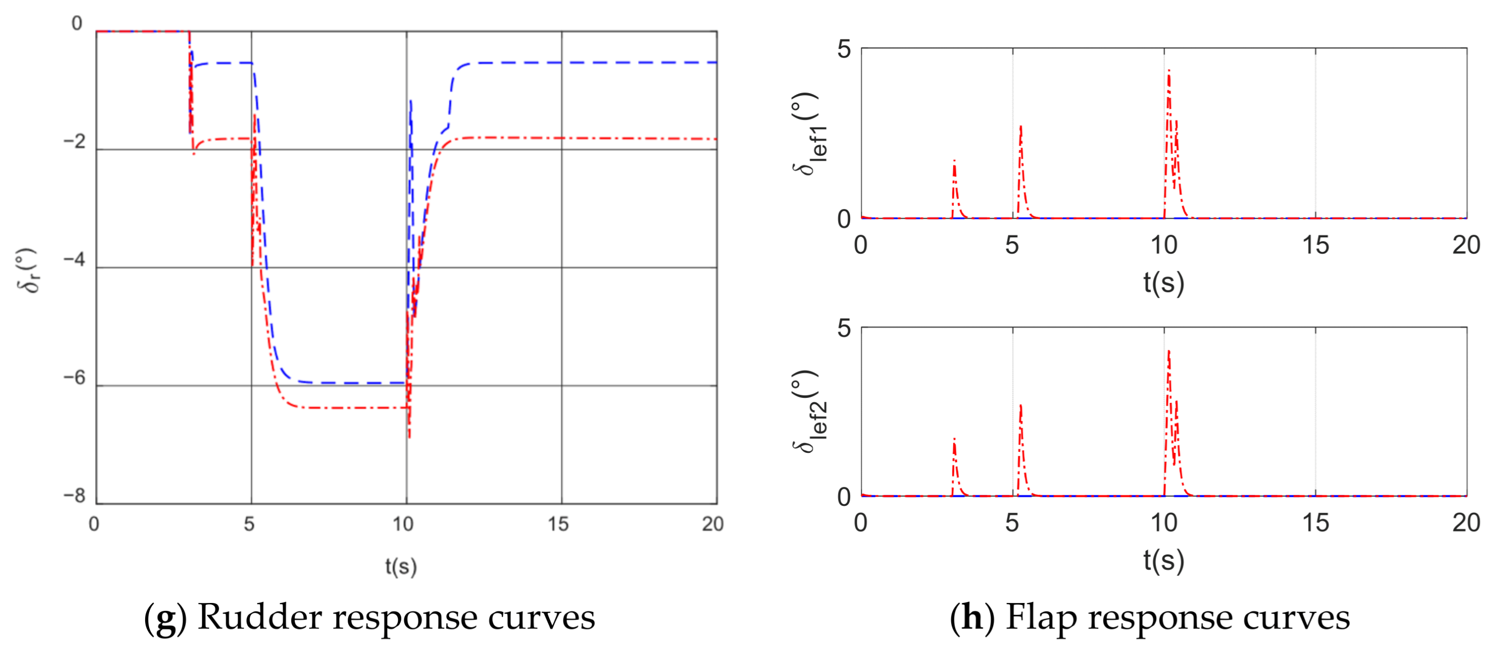
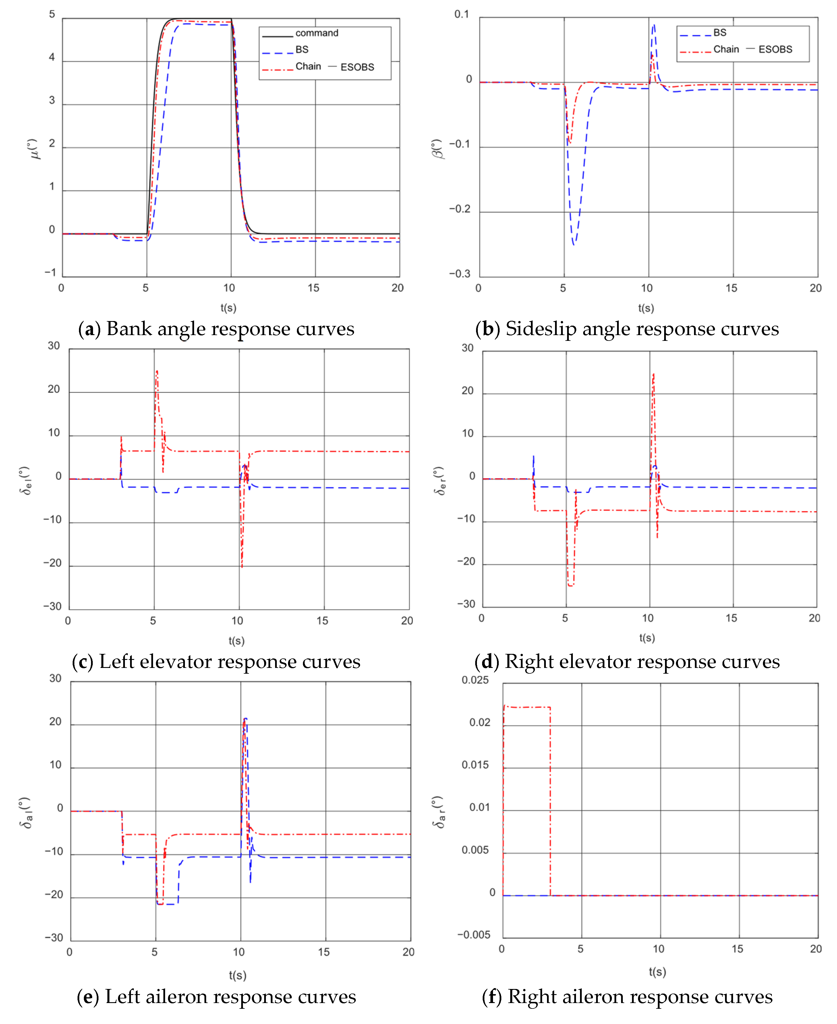
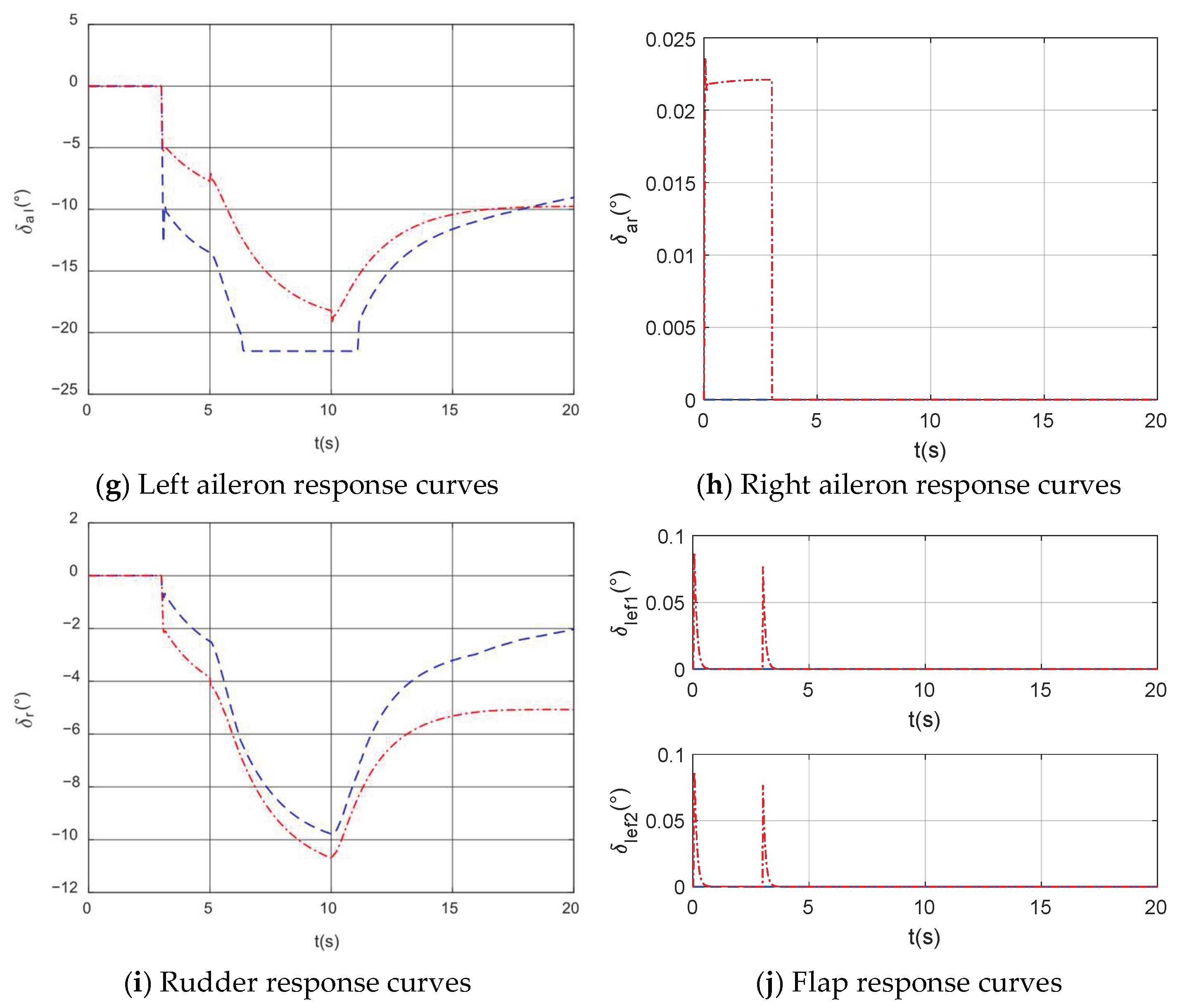
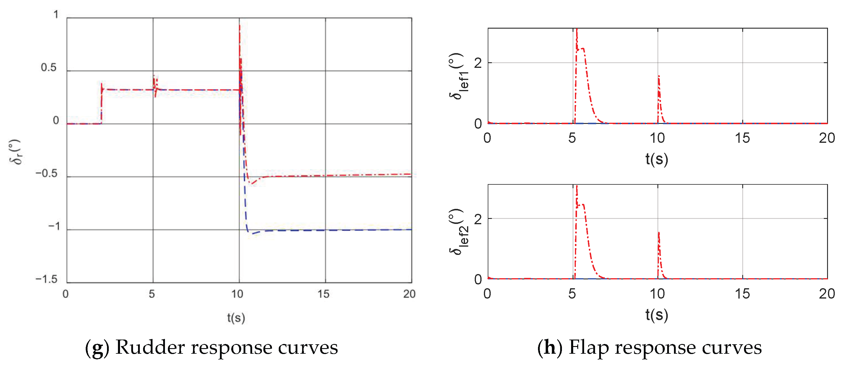
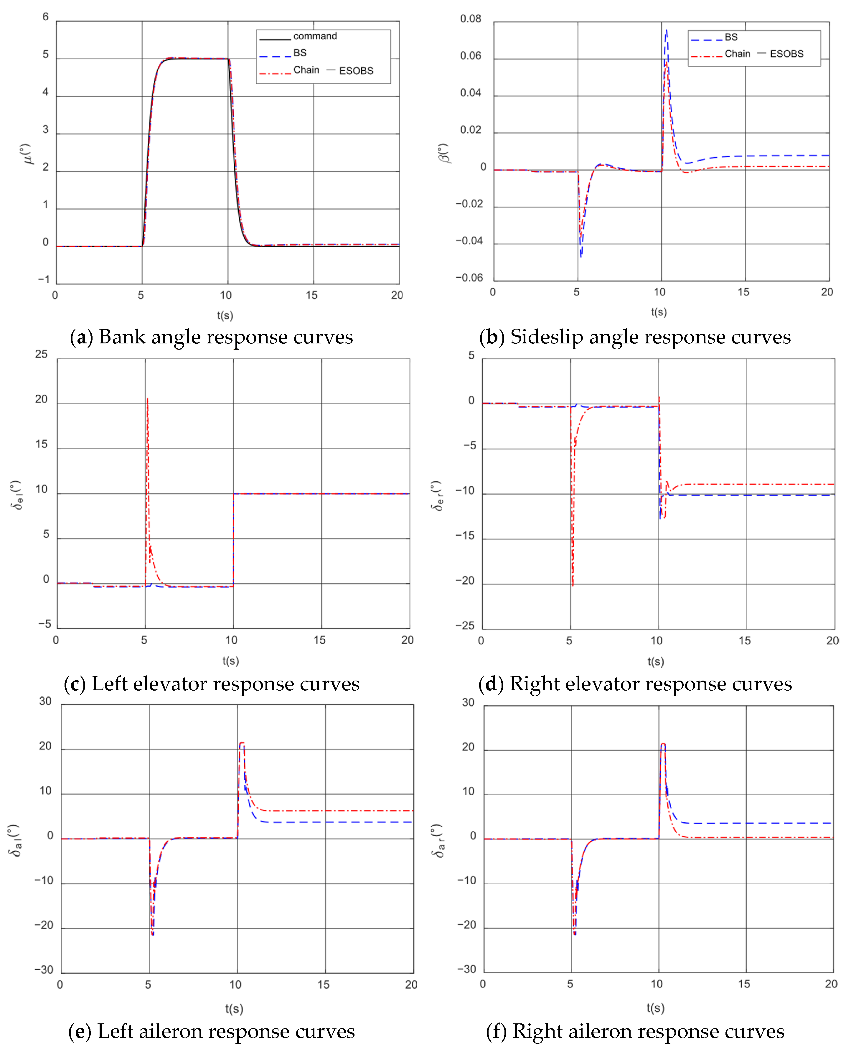
4. Simulation Analysis of Fault-Tolerant Control for Wing Surface Failure

In this section, the control performance and robustness of the backstepping fault-tolerant controller based on the extended state observer are validated under three typical faults (wing damage, control surface damage, and control surface jam). During simulation, the initial states of the aircraft are given in Table 1, the control system update frequency is 50 Hz, and the simulation time is 20 s.

4.1. Simulation of Fault-Tolerant Control for Wing Damage

The fault settings during the simulation process are as follows: The third second after the simulation begins, a fault is introduced to the aircraft, simulating 40% damage to the right wing. At this point, the right aileron is completely detached and becomes inoperative (i.e., the right aileron deflection is fixed at zero), and this condition persists until the end of the simulation. Three sets of simulations are conducted: a set with a square wave signal command for the angle of attack; a set with a square wave signal command for the bank angle; and a set where the airflow angle loop is disconnected, a square wave signal command is given for the pitch rate, and the sideslip angle is maintained at zero.
Under the same command inputs and fault conditions, the control effects of the ESOBS and BS controllers with series connection are compared. BS represents the control effect of backstepping, and Chain-ESOBS represents the control effect of the backstepping of a finite-time observer with a chain. The simulation results are shown in Figure 2, Figure 3 and Figure 4.
According to the simulation results, after the aircraft experiences a 40% wing surface damage fault, the reduction in the right wing area leads to decreased lift on the right wing. Consequently, the lift on the right wing becomes less than that on the left wing, causing the aircraft to roll to the right. Following wing surface damage, the right aileron becomes inoperative, resulting in a constant right aileron deflection of zero. The left aileron deflects negatively to provide a left rolling moment. The extended state observer estimates the adverse disturbances caused by the right aileron fault, compensating for this in the airflow angle and angular rate loops. Compared to conventional backstepping control, the ESOBS with control allocation demonstrates better bank angle control. As shown in Figure 2 and Figure 3, after a 40% wing surface damage, the left aileron deflects approximately −11° to balance the additional rolling moment. Given the aileron’s deflection limit of ±21.5°, the negative deflection margin of the left aileron is only 10.5°, leading to the prolonged maximum deflection of the left aileron during subsequent bank angle command tracking, as observed in Figure 4, thereby degrading control performance. In contrast, the ESOBS with control allocation compensates for the adverse effects of wing damage by effectively utilizing differential elevator control to achieve bank angle control. Wing surface damage significantly impacts lateral-directional dynamics but has a minimal effect on longitudinal dynamics. Therefore, when a 3° angle of attack command is given, the system can essentially track the desired command, maintaining a sideslip angle of zero.
By disconnecting the airflow angle loop and independently testing the control performance of the ESOBS-based angular rate loop, it is observed that when a certain pitch rate signal is given, the ESO-based backstepping can achieve better control performance. This indicates that the ESO-based backstepping control designed in this paper can achieve fault-tolerant control not only in the airflow angle loop but also in the angular rate loop.

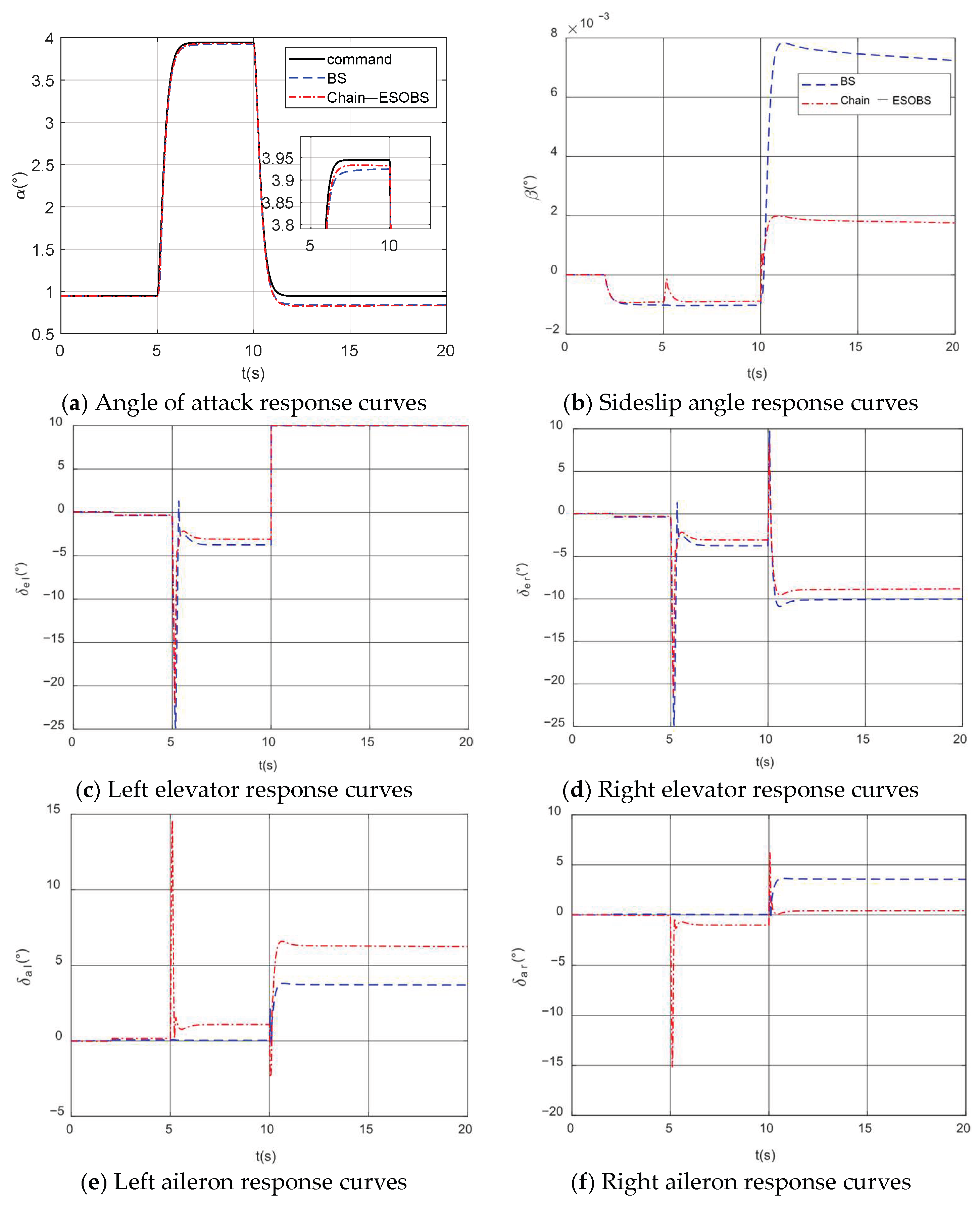
4.2. Simulation of Fault-Tolerant Control for Elevator Failures

Two seconds after the simulation begins, a fault simulating 50% damage to the left elevator is introduced, lasting for 8 s. At 10 s, a left elevator jam fault is introduced, with the jam position at 10° persisting until the end of the simulation. Two sets of simulations are conducted: a set with a square wave signal command for the angle of attack and a set with a square wave signal command for the bank angle, with the sideslip angle maintained at zero.
Under the same command inputs and fault conditions, the control effects of the ESOBS and BS controllers with series connection are compared. The simulation results are shown in Figure 5 and Figure 6.
Figure 5 and Figure 6 demonstrate that the ESOBS control method effectively reconstructs elevator faults. The ESO estimates disturbance signals resulting from elevator faults and feeds them back into the aircraft’s airflow angle and angular rate loops, achieving control over the α and μ . This approach maintains the desired dynamic performance under elevator fault conditions with minimal oscillation, and the sideslip angle remains near zero. However, due to the bounded stability of the ESO, slight tracking errors appear after stabilizing the airflow angles. Compared to standard backstepping control, the ESOBS control with control allocation exhibits superior fault-tolerant performance in the airflow angle loop, providing more precise control. The extended observer is used to estimate the state of the airflow angle and angular velocity and the modeling error of aerodynamic parameters caused by faults in order to solve the problem of the insufficient robustness of traditional backstepping control with faults. Overall, under both controllers, the control surface deflections are smooth without oscillations. With control allocation, the aircraft relies less on the faulty left elevator, instead increasing the deflections of the functional control surfaces and flaps to counteract the moment changes caused by the left elevator fault. This strategy enhances control performance, facilitates quicker fault recovery, and improves command tracking.

5. Conclusions

This paper focuses on fault-tolerant flight control research for aircraft with wing surface faults, utilizing a backstepping approach based on an extended state observer (ESO). Initially, the structure of the ESO is designed for the aircraft’s airflow angle and angular rate loops, and its bounded stability is proven. Subsequently, a fault-tolerant backstepping control law for the airflow angle loop is developed based on the ESO. Finally, the robustness and control performance of the fault-tolerant flight control law are validated under wing surface and control surface faults. Simulation results indicate that the designed ESOBS fault-tolerant controller can effectively overcome parameter uncertainties caused by faults, achieve stable control of airflow angles, and ensure normal flight of the aircraft.

Author Contributions

Conceptualization, Y.G. and B.W.; methodology, Y.G.; software, Y.G.; validation, Y.G.; formal analysis, Y.G.; investigation, Y.G. and B.W.; resources, B.W. and X.L.; data curation, Y.G.; writing—original draft preparation, Y.G., B.W. and X.L.; writing—review and editing, Y.G.; visualization, Y.G.; supervision, Y.G., B.W. and X.L.; project administration, Y.G.; funding acquisition, X.L. All authors have read and agreed to the published version of the manuscript.

Funding

This research is supported by the Key Laboratory of Flight Control Simulation Technology of China.

Data Availability Statement

The data presented in this study are available on request from the corresponding author due to privacy.

Conflicts of Interest

The authors declare no conflicts of interest.

References

  1. Foster, J.; Cunningham, K.; Fremaux, C.; Shah, G.; Stewart, E.; Rivers, R.; Wilborn, J.; Gato, W. Dynamics modeling and simulation of large transport airplanes in upset conditions. In Proceedings of the AIAA Guidance, Navigation, and Control Conference and Exhibit, San Francisco, CA, USA, 15–18 August 2005; p. 5933. [Google Scholar]
  2. Rajagopal, K.; Balakrishnan, S.; Nguyen, N.; Krishnakumar, K. Robust adaptive control of a structurally damaged aircraft. In Proceedings of the AIAA Guidance, Navigation, and Control Conference, Toronto, ON, Canada, 2–5 August 2010. [Google Scholar]
  3. Shah, G. Aerodynamic effects and modeling of damage to transport aircraft. In Proceedings of the AIAA atmospheric flight mechanics conference and exhibit, Honolulu, HI, USA, 18–21 August 2008. [Google Scholar]
  4. Yang, H.; Jiang, B.; Staroswiecki, M. Supervisory fault tolerant control for a class of uncertain nonlinear systems. Automatica 2009, 45, 2319–2324. [Google Scholar] [CrossRef]
  5. Lyu, Y.; Cao, Y.; Zhang, W. Dynamic surface control design of post-stall maneuver under unsteady aerodynamics. Aerosp. Sci. Technol. 2018, 80, 269–280. [Google Scholar] [CrossRef]
  6. Guerreiro, N.M.; Moutinho, A. Robust Incremental Backstepping Controller for the Attitude and Airspeed Tracking of a Commercial Airplane. In Proceedings of the 2019 IEEE 10th International Conference on Mechanical and Aerospace Engineering, Brussels, Belgium, 22–25 July 2019. [Google Scholar]
  7. Cordeiro, R.A.; Azinheira, J.R.; Moutinho, A. Robustness of Incremental Backstepping Flight Controllers: The Boeing 747 Case Study. IEEE Trans. Aerosp. Electron. Syst. 2021, 57, 3492–3505. [Google Scholar] [CrossRef]
  8. Safwat, E.; Zhang, W.; Kassem, M.; Mohsen, A. Robust Nonlinear Flight Controller for Small Unmanned Aircraft Vehicle based on Incremental BackStepping. In Proceedings of the AIAA SciTech Forum, Orlando, FL, USA, 6–10 January 2020. [Google Scholar]
  9. Singh, P.; Salahudden, S.; Karnam, A.; Singh, A. Flight Path Angle Control using Backstepping Dynamic Surface for Non-Strict Feedback System. In Proceedings of the AIAA Aviation Forum and ASCEND co-located Conference Proceedings, Las Vegas, NA, USA, 29 July–2 August 2024. [Google Scholar]
  10. Wang, X.; Van Kampen, E.J. Incremental Backstepping Sliding Mode Fault-Tolerant Flight Control. In Proceedings of the AIAA SciTech Forum, San Diego, CA, USA, 7–11 January 2019. [Google Scholar]
  11. Fei, A.L.; Li, N.; Li, S.Y. Active disturbance rejection backstepping control for UAVs. Control Theory Appl. 2016, 33, 1296–1302. [Google Scholar]
  12. Liu, Y. Research on Fixed-Wing UAV Control Method Based on Backstepping Adaptive; School of Automation, Harbin Engineering University: Harbin, China, 2015. [Google Scholar]
  13. Li, J.; Wang, N.; Hua, Y.; Song, X. Study on Disturbance Observer-Based Backstepping Control for Quadrotor. Comput. Simul. 2020, 37, 28–34. [Google Scholar]
  14. Zhang, Q.; Wang, C.; Xu, D. Robust adaptive backstepping control for a class of non-affine nonlinear system with full states constraints and input saturation. Control Decis. 2020, 35, 769–780. [Google Scholar]
  15. Zhuang, H. Research on Aircraft Attitude Control Method for Strong Disturbance and Maximum Allowable Damage; School of Artificial Intelligence, Nankai University: Tianjin, China, 2021. [Google Scholar]
  16. Zhang, Q.; Xu, H.; Xu, D.; Wang, C. Finite-time convergence backstepping control for a class of uncertain affine nonlinear systems based on disturbance observer. Control Theory Technol. 2020, 37, 747–757. [Google Scholar]
  17. Xu, H.; Yu, D.; Sui, S.; Zhao, Y.-P.; Chen, C.P.; Wang, Z. Nonsingular practical fixed-time adaptive output feedback control of MIMO nonlinear systems. IEEE Trans. Neural Netw. Learn. Syst. 2022, 34, 7222–7234. [Google Scholar] [CrossRef] [PubMed]
  18. Al-Dujaili, A.Q.; Humaidi, A.J.; Pereira, D.A.; Ibraheem, I.K. Adaptive backstepping control design for ball and beam system. Int. Rev. Appl. Sci. Eng. 2021, 12, 211–221. [Google Scholar] [CrossRef]
  19. Hu, J.; Huang, J.; Gao, Z.; Gu, H. Position tracking control of a helicopter in ground effect using nonlinear disturbance observer-based incremental backstepping approach. Aerosp. Sci. Technol. 2018, 81, 167–178. [Google Scholar] [CrossRef]
  20. Wen, Y.; Zhou, Z.; Zhou, W.; Tang, X. Attitude Control of Quadrotor UAV Based on Extended State Observer and Backstepping Method. Meas. Control Technol. 2020, 39, 141–146. [Google Scholar] [CrossRef]
  21. Qin, H.; Chen, Z.; Sun, M. Longitudinal Control of Nonlinear Supercavitating Vehicle Based on Extended State Observer and Backstepping Method. Control Theory Appl. 2023, 40, 373–380. [Google Scholar]
  22. Zhao, M.; Wang, Y.; Wang, Y. Adaptive Backstepping Sliding Mode Control of SMA Drive System Based on Extended Observer. Mech. Electr. Eng. Technol. 2025, 1–7. [Google Scholar]
  23. Li, X.; Wang, C.; Guo, Y.; Li, A. Cooperative control for flight formation of tandem-rotor wheeled UAVs. Acta Aeronaut. Astronaut. Sin. 2022, 45, 1–12. [Google Scholar]
  24. Li, Y.; Wen, C.Y.; Liu, X.; Zhang, W.; Zheng, Y. Prescribed-Time Fault-Tolerant Flight Control for Aircraft Subject to Structural Damage. IEEE Trans. Aerosp. Electron. Syst. 2024, 61, 1848–1859. [Google Scholar] [CrossRef]
  25. Ming, R.; Liu, X.; Li, Y.; Zhang, W. Research on a backstepping flight control method improved by STFT in atmospheric disturbance applications. Proc. Inst. Mech. Eng. Part G J. Aerosp. Eng. 2024, 238, 1534–1547. [Google Scholar] [CrossRef]
Figure 1. Block diagram of ESOBS-based fault-tolerant control structure for airflow angle loop.
Actuators 14 00206 g001
Figure 2. Comparison of aircraft state responses under angle of attack commands with right wing damage.
Actuators 14 00206 g002aActuators 14 00206 g002b
Figure 3. Comparison of aircraft state responses under bank angle commands with right wing damage.
Actuators 14 00206 g003aActuators 14 00206 g003b
Figure 4. Comparison of aircraft state responses under pitch rate commands with right wing damage.
Actuators 14 00206 g004aActuators 14 00206 g004b
Figure 5. Comparison of aircraft state responses under angle of attack commands with left elevator failure.
Actuators 14 00206 g005aActuators 14 00206 g005b
Figure 6. Comparison of aircraft state responses under bank angle commands with left elevator failure.
Actuators 14 00206 g006aActuators 14 00206 g006b
Table 1. Aircraft trim condition during simulation.
StateSymbolUnitTrim Value
Thrust F T N 126,588.7576
Left Elevator Deflection Angle δ e l deg 0.074002
Right Elevator Deflection Angle δ e r deg 0.074002
Left Aileron Deflection Angle δ a l deg 0
Right Aileron Deflection Angle δ a r deg 0
Rudder Deflection Angle δ r deg 0
Flap Deflection Angle δ l e f deg 0
Angle of Attack α deg 0.94483
Sideslip Angle β deg 0
Flight Altitude H m 4000
Flight Velocity V m / s 200
Disclaimer/Publisher’s Note: The statements, opinions and data contained in all publications are solely those of the individual author(s) and contributor(s) and not of MDPI and/or the editor(s). MDPI and/or the editor(s) disclaim responsibility for any injury to people or property resulting from any ideas, methods, instructions or products referred to in the content.

