Abstract
To further solve the problems of commercial vehicle electronic parking brake systems under typical operating conditions, such as manual parking/release, emergency parking, ramp parking leakage, and so on, a new bistable electronic parking brake system (EPB) is proposed and studied in this paper. First, the principle of the proposed bistable electronic parking brake system is described. Then, the control parameters of the electronic parking brake system are presented in detail, and the design scheme of the automatic parking/release control strategy is listed. Subsequently, an experimental road test system is designed, and the excellent performance of the designed bistable EPB is demonstrated by said road experiments. The research results show that the presented bistable EPB can effectively solve the problems of high-speed parking and ramp parking failure and significantly improve the braking safety of the whole vehicle.
1. Introduction
With the acceleration of the automobile industry toward electric, intelligent, network upgrading, coupled with the increasing number of cars, urban road conditions are increasingly congested, and cars start and stop frequently [1]. Although the electronic parking brake system (EPB) integrates the functions of temporary braking and parking long-term braking and uses electronically controlled real parking brake [2,3,4], under the complex and tedious starting, parking, and parking brake operations, especially in the typical operating conditions of commercial vehicles, such as emergency parking [5,6,7] and ramp parking [8,9,10,11], there are problems such as leakage [12,13], which bring trouble to and affect the safety of driving. To further improve the reliability and safety of a commercial vehicle electric parking brake system under these operating conditions, the new electronic parking brake system needs to be studied urgently.
Liu P [14] and others proposed an optimized parking control strategy for electric vehicles driven by a switched reluctance motor. Schlimme [15] and others introduced the redundant design of a line control system given the serious safety problems caused by a single-point failure. Bagherpour [16] and others discussed at length the sensitivity of an air braking system in heavy vehicles to air leakage and found that air leakage will significantly affect braking performance. Jo [17] discussed that human-made braking system actuator stagnation fault would seriously threaten driving safety, which requires optimization to solve the braking problem of commercial vehicles under complex operating conditions. Henderson [18] and others used a fast-acting bistable valve to design a pressure modulator, which shows the unique advantage of a bistable valve in pressure control. The main actuator of the new bistable electronic parking brake system is the solenoid valve [19], which controls chamber pressure and the double-stable valve (SSV). The system improves the accurate control ability of parking brakes through the combination of several solenoid valves and SSV. With its unique bistable structure and two stable states, SSV can maintain the current working state without a continuous power supply, which greatly improves the stability and reliability of the system.
In vehicle braking systems, traditional electronic parking brake (EPB) systems rely on continuous motor operation and complex multi-source information integration. They have numerous components, high failure risks, and high costs and energy consumption [20,21]. The newly designed bistable EPB system uses solenoid valves controlled by pulse signals. It simplifies control logic, is energy-efficient (maintaining the state without continuous power), reduces manufacturing and maintenance costs, and has enhanced reliability due to fewer failure-prone components. Overall, the bistable EPB system outperforms traditional ones in energy efficiency, cost-effectiveness, and reliability.
Thus, this paper will first describe its structure principle and control scheme, and then discuss the design of the typical control logic. Finally, through the design of the road experimental system, the excellent performance of the proposed new bistable EPB system is clarified.
2. Bistable EPB Scheme and Braking Principle
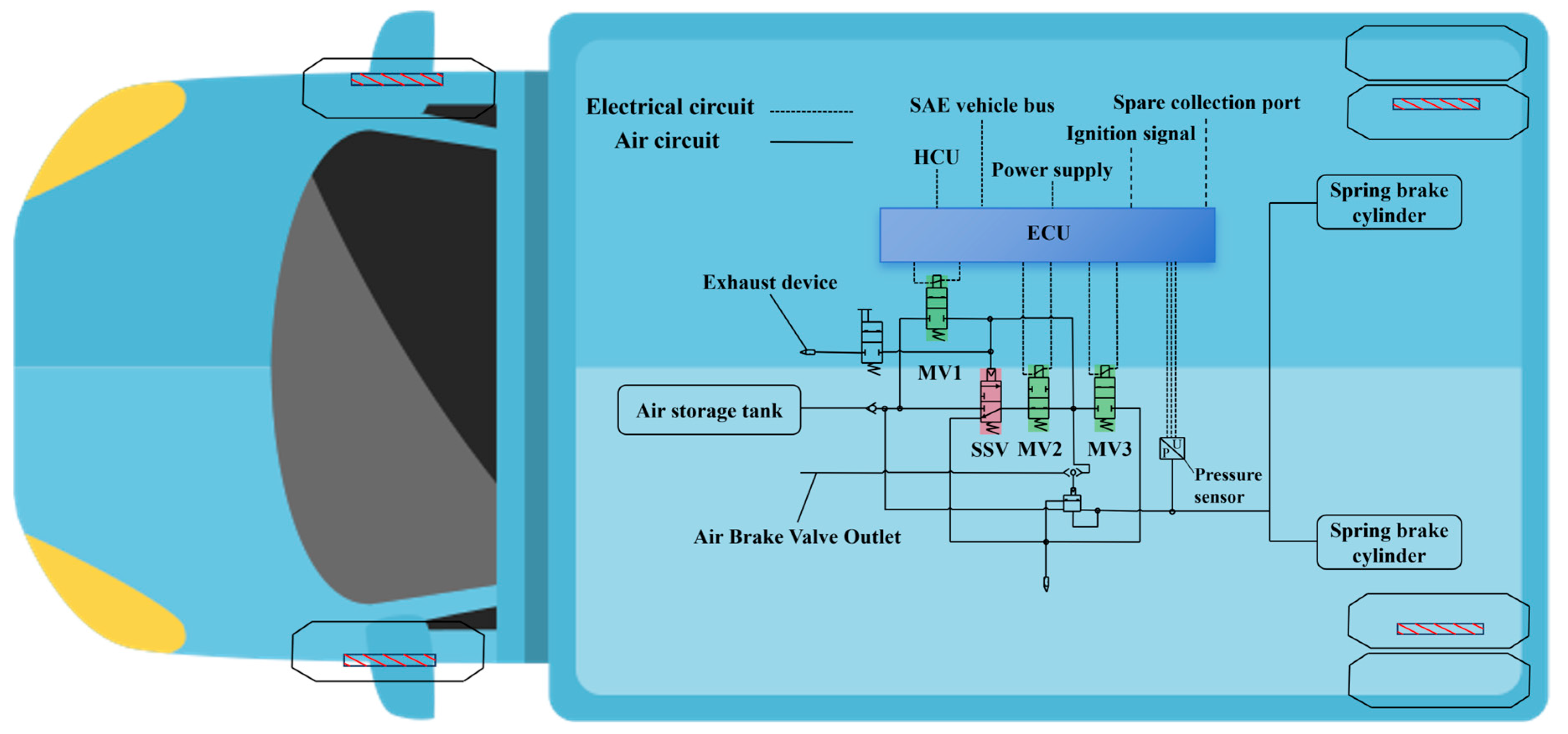
According to the structure and working principle of the bistable electronic parking brake system, Figure 1 illustrates the structural principle diagram of the bistable scheme design. The key part, the SSV valve, is a three-way, two-position, normally closed, directly pneumatically actuated valve with a mechanical spring return, which is monostable by nature. However, when integrated with solenoid valves MV1, MV2, and MV3 in the system, it contributes to system-wide bistability. The system can stably hold two critical states: parking and releasing. By means of signals fed into the solenoid valves and the resultant changes in chamber pressure, it precisely controls the opening/closing and flow direction of the gas path. For example, during parking, certain solenoid valves reset the SSV valve, while during releasing, others pressurize it. This coordinated operation guarantees reliable and stable control of the braking system under diverse working conditions, enabling accurate and stable gas-path switching during the transition between parking and driving brakes. In essence, bistability here does not pertain to the SSV valve alone but to the system’s overall behavior. When the SSV valve collaborates with the solenoid valves and the gas-path control mechanism, the system can sustain the parking and releasing states steadily without a continuous power supply to the SSV valve, which represents the real significance of the system’s bistability.

Figure 1.
Junction principle composition of bistable electronic parking brake system.
The air circuit system takes the air storage tank as the air source to supply compressed air. The ECU receives signals from the vehicle bus, ignition signals, and so on. It controls the opening and closing states of solenoid valves MV1, MV2, and MV3, as well as the SSV valve, thus accurately regulating the on/off status and flow direction of the air within the air circuit. Meanwhile, the pressure sensor monitors the chamber pressure in the air circuit in real-time and sends feedback to the ECU. The compressed air goes through the control area of the air circuit. When braking, it flows to the spring brake cylinder via the outlet of the air brake valve to implement braking. When the brake is released, the exhaust device expels the compressed air in the air circuit, returning the brake cylinder to its original state.
The bistable electronic parking brake system, grounded in the EPB function, features a braking principle where the SSV valve works in concert with solenoid valves MV1, MV2, and MV3 to confer system-wide bistability. When releasing the EPB, MV1 and MV2 are powered on briefly and then de-energized; after which, the SSV valve is pressurized to link the EPB control cavity with the air storage tank mouth. When parking, MV2 and MV3 are powered on and then power-off follows, and the mechanical spring resets the SSV valve, enabling the EPB control cavity to attain a stable state with the atmosphere. In this way, through such precise gas-path control, the system realizes the release, parking, and state-maintenance of the EPB, with its bistability allowing for the reliable and energy-efficient upkeep of these two states without continuous power supply to the SSV valve.
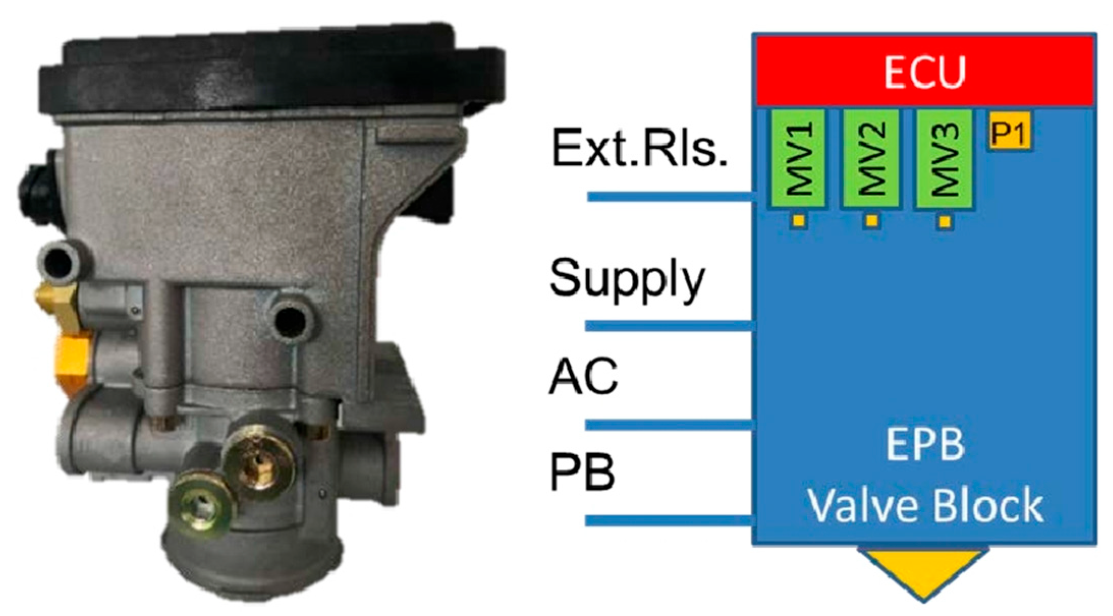
The schematic diagram of the EPB valve module is shown in Figure 2. The ECU, as the control core, sends instructions after processing signals. Solenoid valves MV1, MV2, and MV3 regulate gas flow following these instructions, and the P1 pressure sensor provides pressure feedback. The Ext.Rls. port connects to external release-related devices, and the supply port supplies power. The AC port receives AC signals, which power specific components or are used for communication. The PB port is linked to the parking brake switch, and when the switch is operated, it sends signals to the module to control the parking brake function. All these ports enable the EPB valve module to work in harmony with other vehicle systems.

Figure 2.
EPB valve module scheme diagram.
3. Design of Control Parameters and Control Strategy
3.1. Electronic Parking Control Parameters
In this experiment, many kinds of signals are tested, including solenoid valves MV1, MV2, and MV3; chamber pressure; PB status; HCU stroke; brake switch; key position; vehicle speed; Hill_Mode; and other signals.
- (1)
- Solenoid valve switch signal
By testing the signals of these solenoid valves, we can see whether they are working properly and whether they can be opened and closed accurately according to the instructions of the system, as well as their response speed and other performance indicators. Their working status is shown in Table 1.

Table 1.
Working state of solenoid valve switch signal.
- (2)
- Chamber pressure signal
The pressure signal reflects the pressure in the chamber. By monitoring this signal, we can judge whether the pressure of the system is within the normal range and whether there are problems such as pressure leakage. Its working status is shown in Table 2.
Table 2.
Chamber pressure signal working state.
- (3)
- PB status signal
The PB status signal is used to indicate the working state of the EPB, such as whether it is in the parking brake state, whether the braking is effective, etc., as shown in Table 3.
Table 3.
PB status signal working state.
- (4)
- HCU stroke signal
This signal reflects the opening of the EPB switch, that is, the braking strength adjustment of the EPB system. Its working state is shown in Table 4.
Table 4.
HCU stroke signal working state.
- (5)
- Brake switch signal
The brake switch signal is used to determine whether the driver has pressed the brake pedal and to what extent. This signal is the key input signal of the automobile braking system, which directly determines whether the braking system should start and the braking strength, as well as its working state, as shown in Table 5.
Table 5.
Brake switch signal.
- (6)
- Key position signal
The signal indicates the working state of the vehicle’s ignition system, such as whether it is in the ignition start state, whether the key is in the correct position, and so on. It is of great significance to the start-up of the vehicle, the operation of the engine, and the working of the whole vehicle electrical system. Its working status is shown in Table 6.
Table 6.
Key position signal working state.
- (7)
- Speed signal
Speed signal is one of the important parameters of vehicle operation; it reflects the speed of the vehicle. Its working status is shown in Table 7.
Table 7.
Speed signal working state.
- (8)
- Hill_Mode signal
The Hill_Mode can accurately sense the slope when parking, automatically apply appropriate braking force, prevent vehicles from slipping on a ramp, and ensure safety when parking (Table 8).
Table 8.
Hill_Mode signal working state.
The collaborative analysis of these signals can provide a rich and valuable reference for the performance optimization of the EPB system and the improvement of the overall safety and reliability of vehicles.
3.2. Design of Electronic Parking Control Strategy
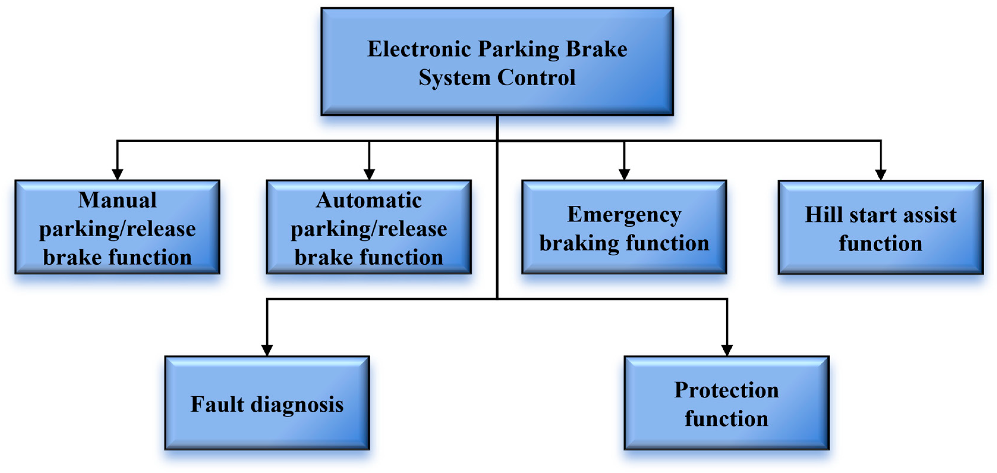
In this paper, to realize the automatic control of the electronic parking brake system and reduce the complexity of vehicle operation, the automatic control function of the system is designed, as shown in Figure 3. According to the driving demand, the parking brake function, automatic parking/release function, emergency braking function, fault diagnosis and protection function, ramp assist function, and other functions are designed.
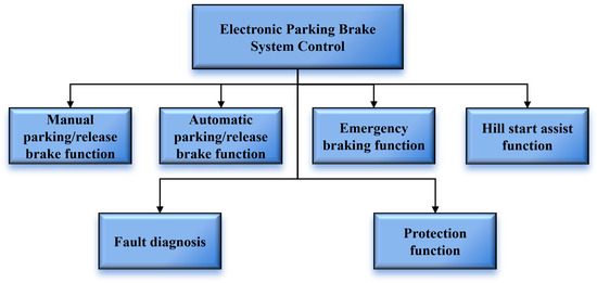
Figure 3.
System function control chart.
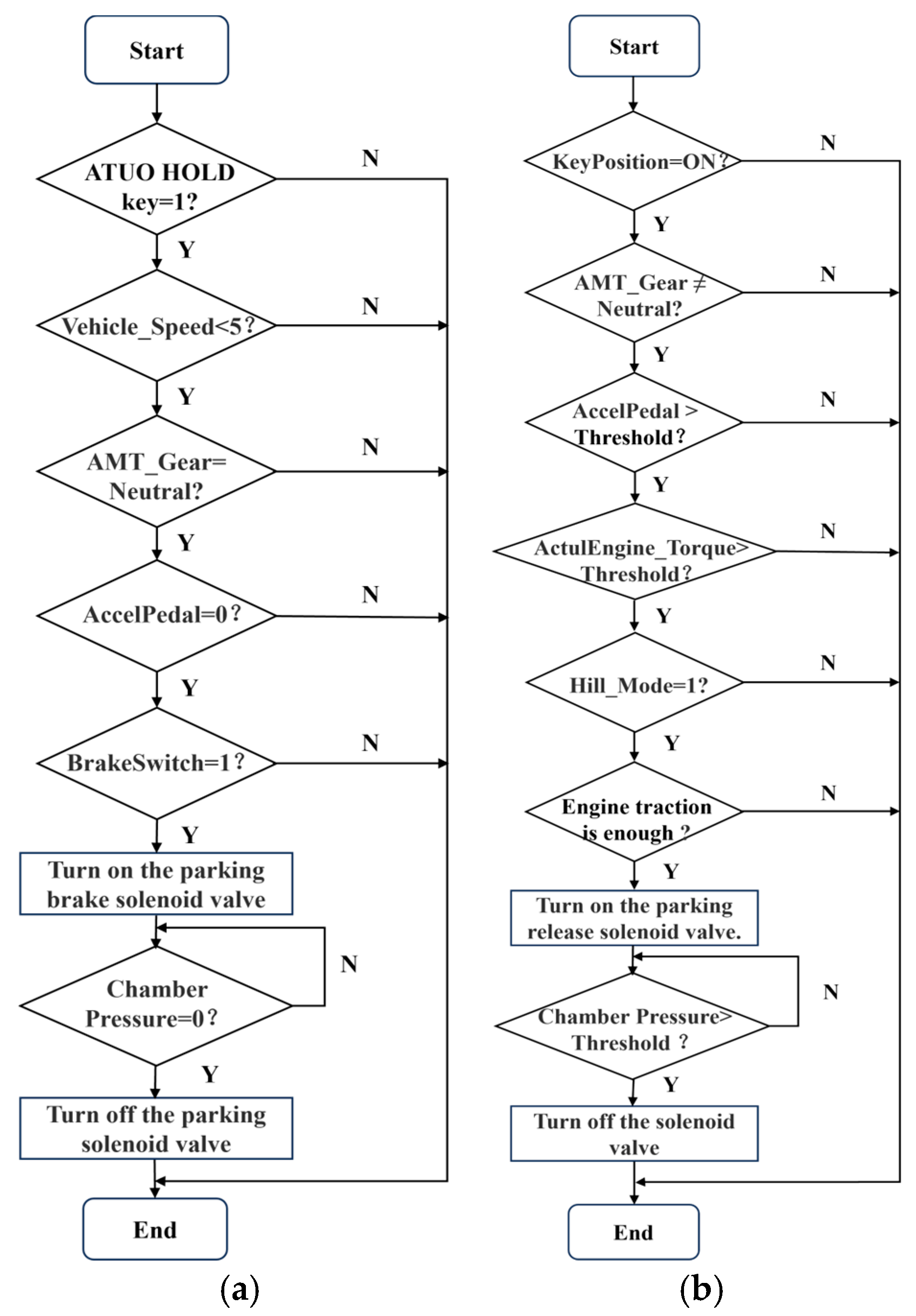
The automatic parking/release function of the vehicle is taken as an example to illustrate the control strategy logic of the system. Its control flow is shown in Figure 4.
(1) The automatic parking brake function operates as follows: after the driver switches off the vehicle and brings it to a stop, the system monitors various pieces of information, including the status of the AUTO HOLD key, vehicle speed, gear position, throttle pedal position, and brake pedal status. By analyzing these data, the system determines whether the driver intends to park. If a parking demand is detected, the system activates the solenoid valves of the EPB system. This action applies the parking brake to the wheels, effectively securing the vehicle in its parked position and ensuring stability.
(2) The automatic release parking function is designed to work in the following manner: when the driver intends to drive away, the system constantly monitors multiple parameters. These include the opening of the acceleration pedal, the current gear position, the status of the ignition switch, the engine speed, the actual torque output, and the road inclination angle (represented by the Hill_Mode signal). By comprehensively analyzing these data, the system determines whether to release the EPB. If the conditions are met, the system activates the solenoid valve to carry out the EPB release operation, enabling the vehicle to move forward smoothly. However, if the detected parameters indicate that the vehicle does not have sufficient power or meets other release-inhibiting conditions, the system will maintain the parking state to prevent any potential danger, such as the vehicle rolling on an incline.
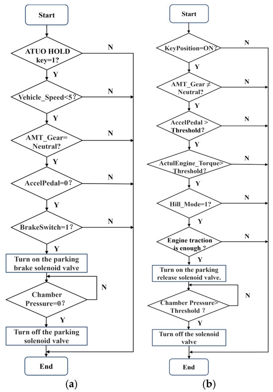
Figure 4.
EPB automatic parking/release control flow chart. (a) Automatic parking brake control flow chart. (b) Flat ground automatic release control flow chart.
4. Experimental Tests and Results
4.1. Test Platform Construction
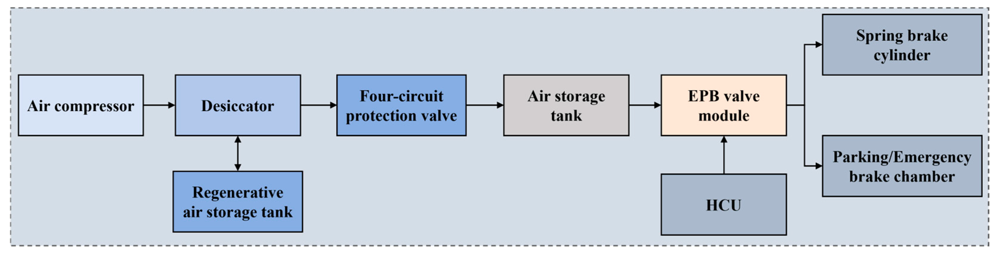
The valve test bench is constructed according to the system scheme diagram. The design scheme of the valve test bench is shown in Figure 5.

Figure 5.
Test schematic diagram.
It is mainly composed of an air compressor, desiccator, four-circuit protection valve, air storage tank, EPB valve module, spring brake cylinder, brake chamber, HCU, and regenerative air storage tank. The function of the air compressor is to compress air and provide an air source for the system. The desiccator removes moisture and other impurities in the compressed air. The four-circuit protection valve distributes compressed air to different independent air paths to ensure safety. The air storage tank is used to store compressed air and stabilize the chamber pressure. The EPB valve module is used to receive signals and control the movement of the brake cylinder and the brake air chamber. The spring brake cylinder is used to perform the parking brake function. The brake chamber is used to perform the braking function. The HCU is used to manually control the braking operation. The regenerative air storage tank is used for storing dry compressed air, providing regenerative air for the desiccator, reducing the water vapor content of the gas, and protecting the braking system. Meanwhile, the JAK tractor is selected as the experimental prototype, and its parameters are shown in Table 9.
Table 9.
Parameters of JAK tractor.
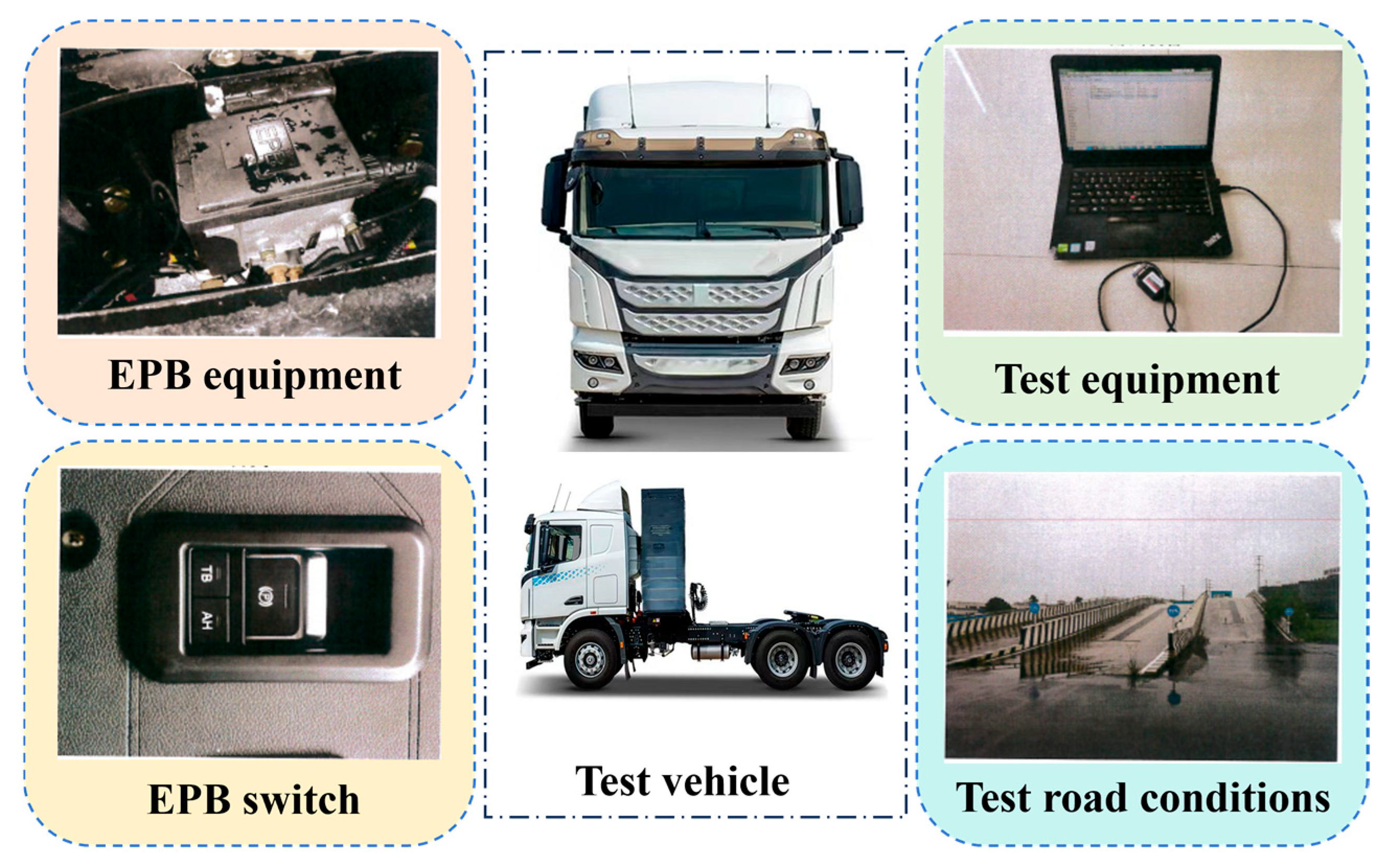
The road test platform is shown in Figure 6. The computer is utilized to collect and analyze vehicle operation data, such as speed, braking pressure, and other parameters. The EPB equipment and switch are the core test objects, which are used to test response speed, braking effect, and other performance indicators and compatibility. The test road conditions include flat roads, ramps, and other types, which can comprehensively evaluate the performance of the braking system in various scenarios and ensure its safety and reliability in practical use. Thus, a real and effective test environment for braking system performance evaluation by integrating vehicles, equipment, braking components, and different road conditions are constructed.
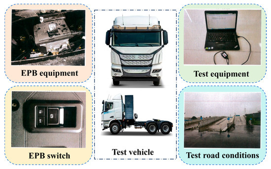
Figure 6.
Road test platform system.
4.2. Road Test Performance
In this paper, the EPB performance of a JAK tractor is tested under typical working conditions, such as manual parking/release, emergency braking, uphill start, downhill start, and so on.
4.2.1. Manual Parking/Release
The EPB system has automatic function and manual operation modes. Testing manual parking and release can ensure the integrity of the system function. Although the automatic function is convenient, it may be affected by electronic system failures, circuit problems, etc. Manual operation as a standby mode and its reliability and stability need to be verified by experiments to ensure that the driver can effectively control the parking state of the vehicle under various conditions.
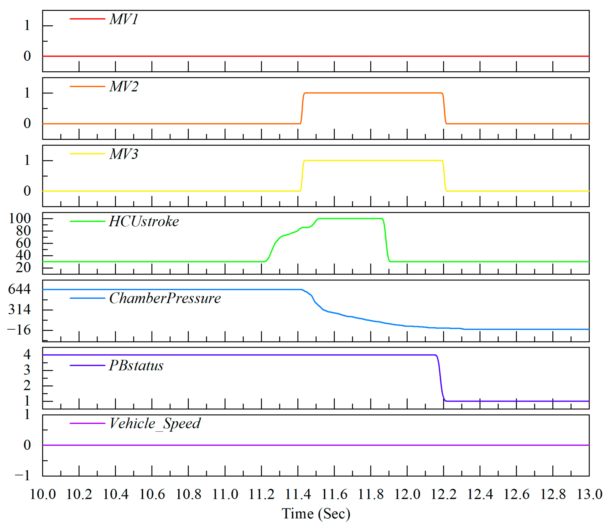
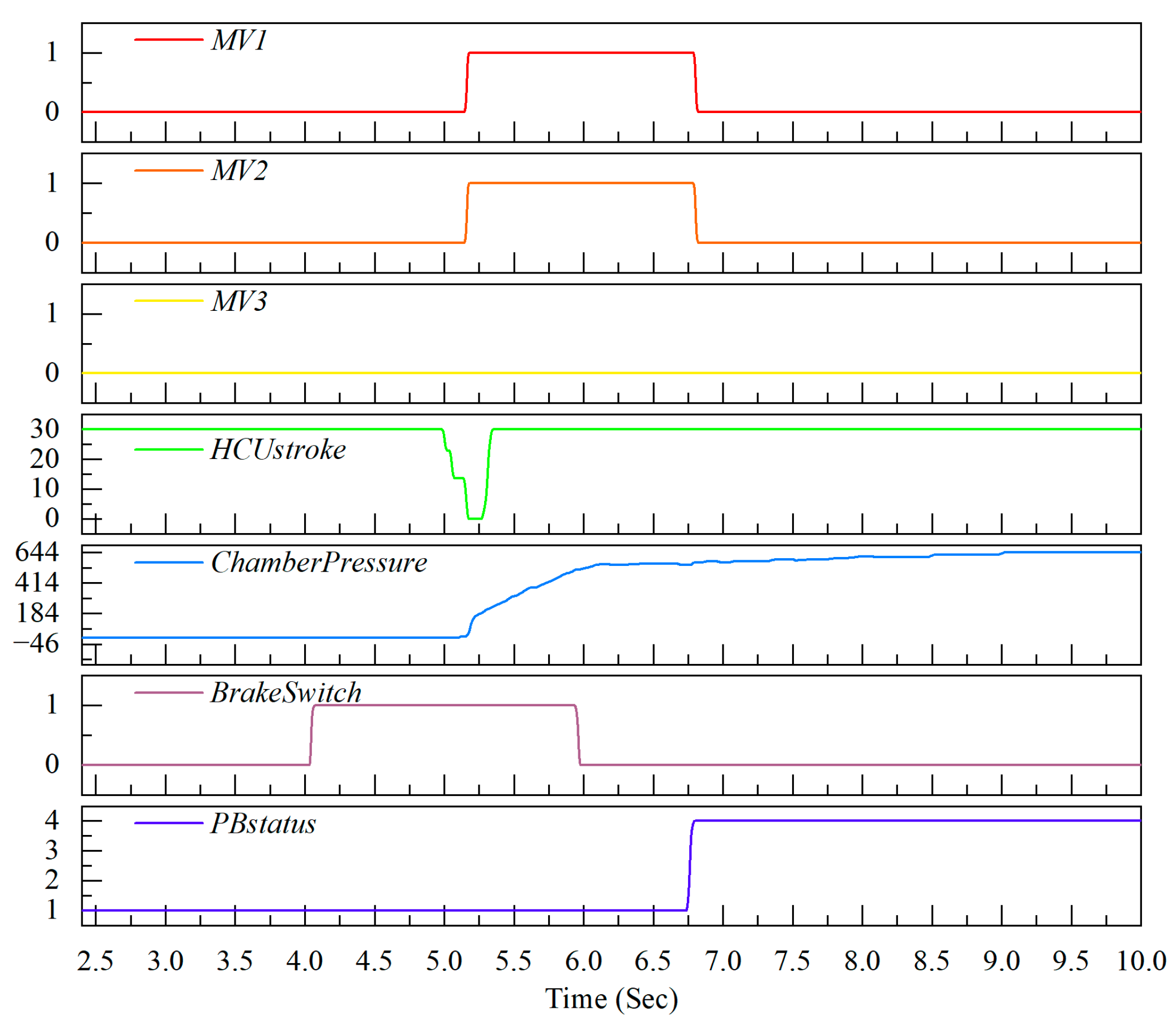
The EPB manual parking test results are shown in Figure 7. During the initial state, the vehicle is at rest and the chamber pressure is 644 kPa. When the EPB switch is pulled up for manual parking operation, the solenoid valves MV2 and MV3 operate, the chamber pressure decreases, the EPB working state changes from release to parking, and the SSV valve is returned.
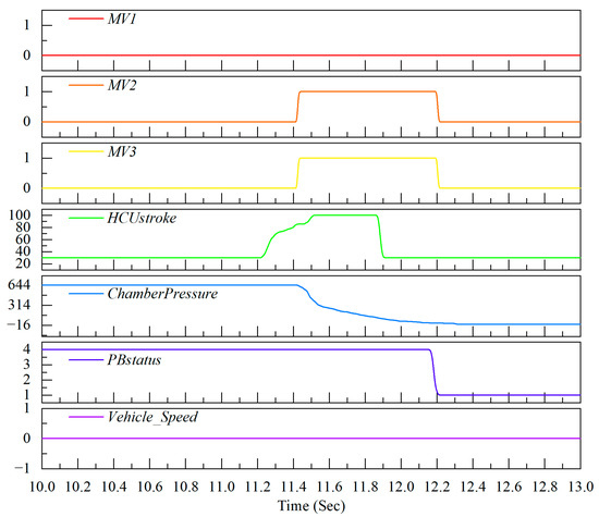
Figure 7.
Manual parking.
The experimental results of the manual release of EPB are shown in Figure 8. In the initial state, the pressure is 0 kpa, the EPB is parked, and the brake pedal is not pressed. When operating, press the brake pedal first, then press the EPB switch. When the solenoid valves MV1 and MV2 move, the chamber pressure rises, the EPB working state changes from parking to release, and the SSV valve is pressed by chamber pressure.
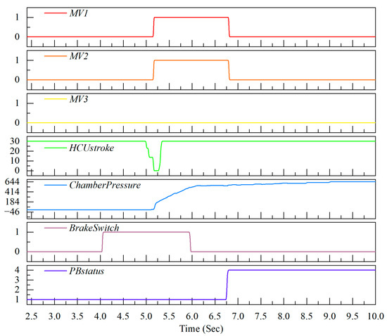
Figure 8.
Manual release.
To summarize, in the manual parking experiment, pulling up the EPB switch makes the solenoid valves MV2 and MV3 operate; the chamber pressure is reduced and the EPB is changed from release to parking. In the manual release experiment, one must first step on the brake pedal and then press the EPB switch; the solenoid valves MV1 and MV2 act, the chamber pressure rises, and the EPB is changed from parking to release. The experimental results show that the manual parking and release function can switch the EPB state according to the preset logic, and the solenoid valves of the system cooperate well and operate stably and reliably.
4.2.2. Emergency Braking Condition
Under emergency braking conditions, the importance of EPB is that it can provide additional braking protection, enhance braking stability, simplify the operation flow, and optimize in coordination with other systems to help vehicles brake more safely and effectively and reduce the risk of accidents [18].
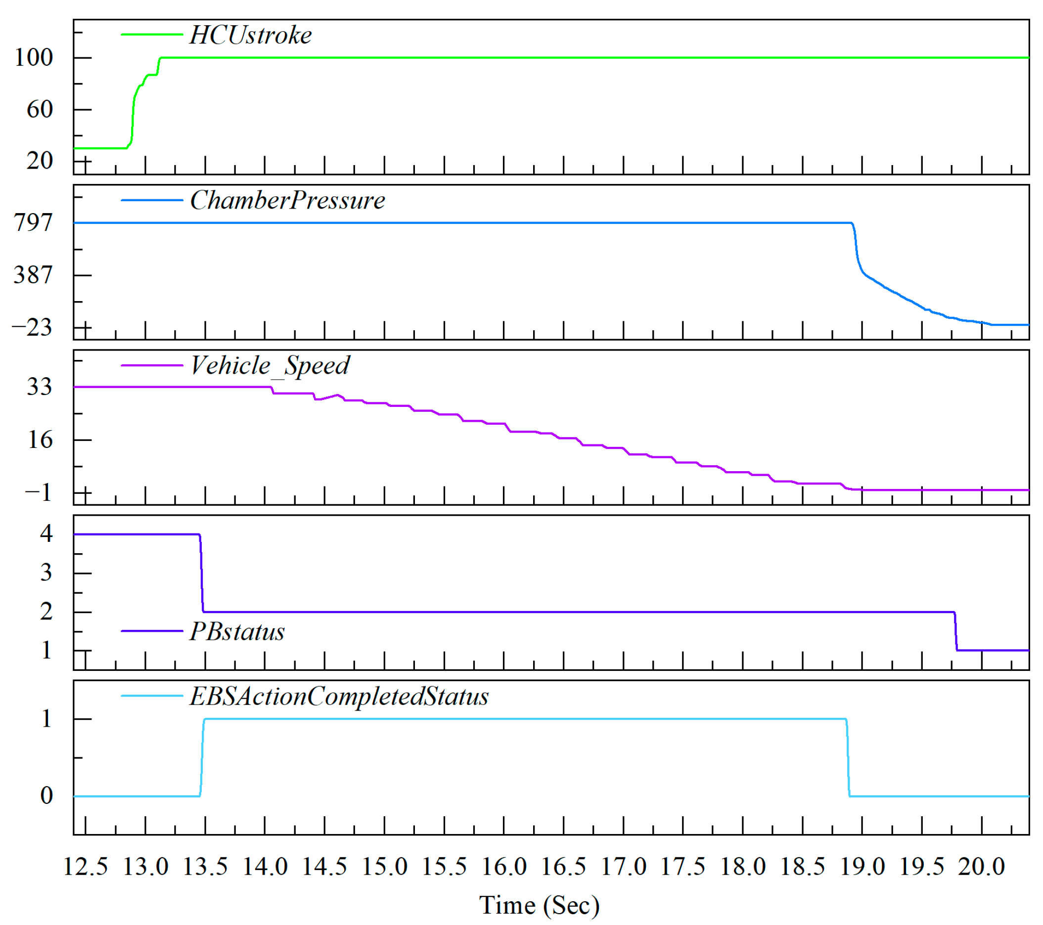
The emergency braking test results are shown in Figure 9. At the start, the chamber pressure was 797 kpa, the vehicle speed was 33 km/h, and the EPB was released. Pulling the EPB switch during driving triggered emergency braking, with the EBS activating simultaneously. The vehicle’s speed dropped to 0, the EBS stopped braking, and the chamber pressure dropped to 0, putting the EPB in the parking state. The average deceleration of emergency braking was about 2.1 m/s2, exceeding the national standard [22].
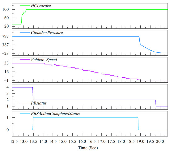
Figure 9.
Emergency braking test result chart.
4.2.3. Hill Start Condition
In this experiment, to prevent vehicle leakage/creep on ramps, three different slope start automatic release conditions were tested; the slopes were 5%, 10%, and 20%, respectively. This comprehensive evaluation aims to assess the performance of the relevant systems under various slope conditions, ensuring that the system can operate stably and safely in all practical scenarios.
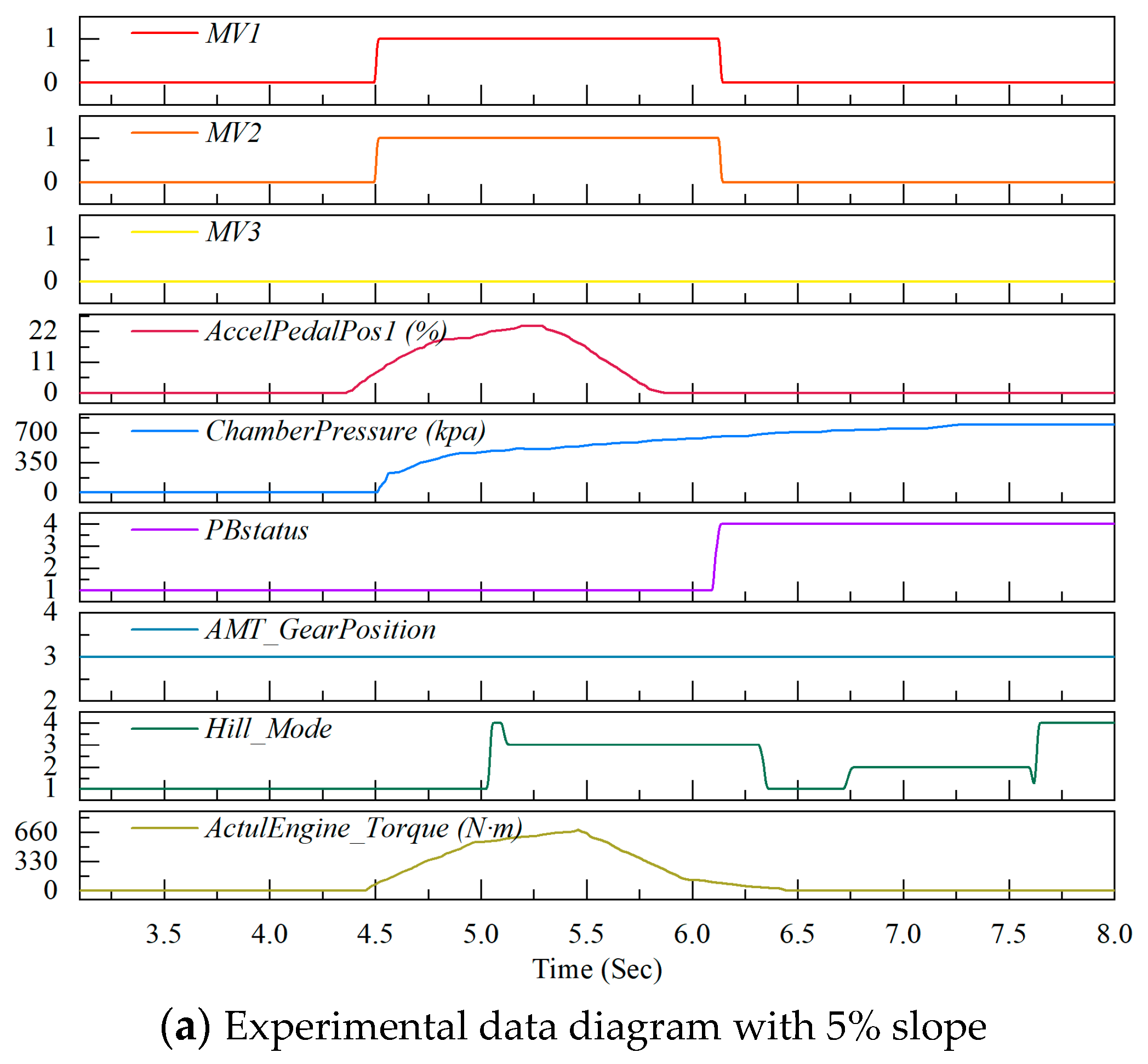
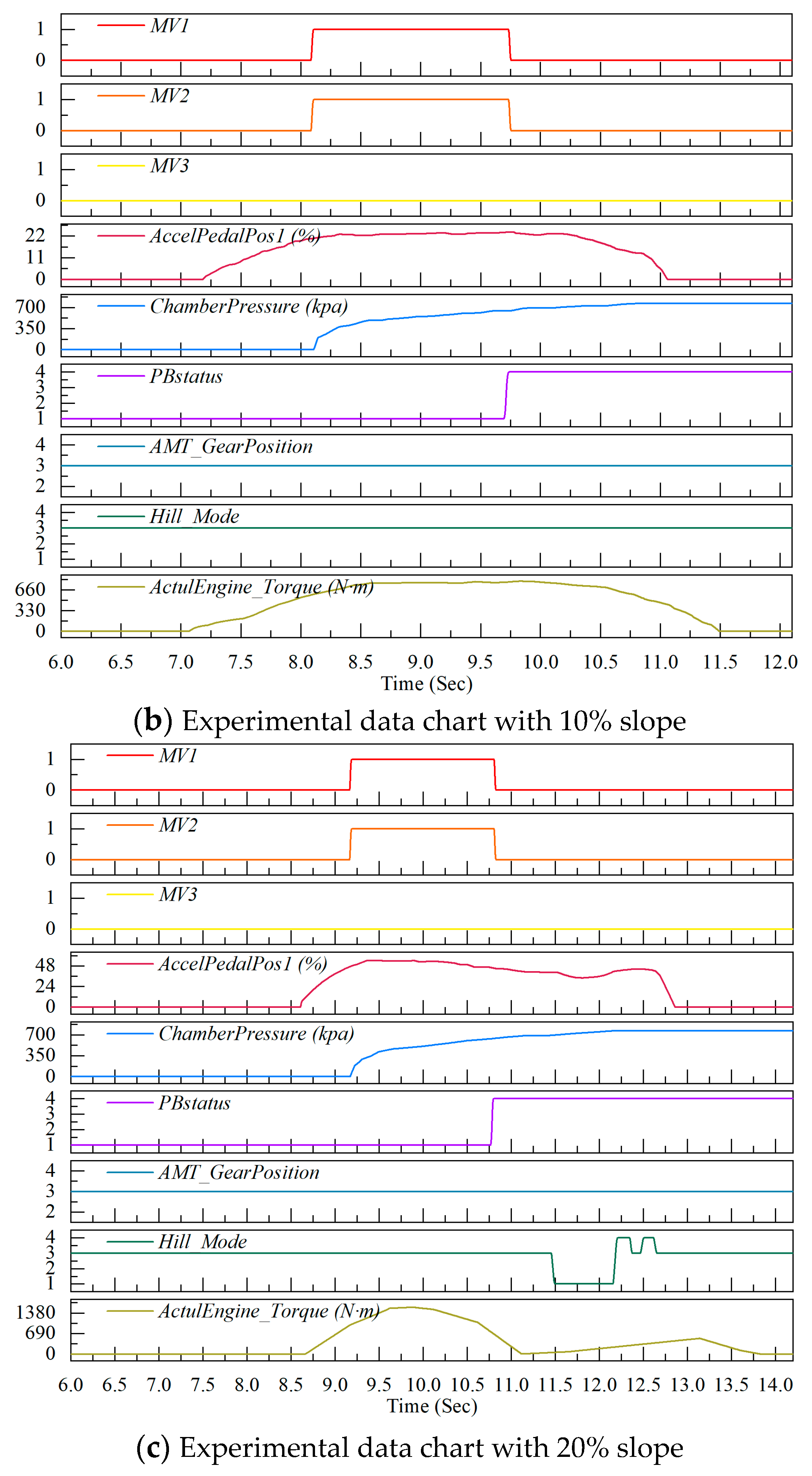
The experimental results of the vehicle starting on the ramps with different slopes are shown in Figure 10. Under the automatic release conditions for starting uphill on three slopes (5%, 10%, and 20%), the initial gear of the vehicle was set to the forward gear AMT Gear Position = 3, the chamber pressure was 0 kpa, the accelerator pedal was not pressed (AccelPedaIPos1 = 0), the EPB was in the parking state, and the actual torque ActuIEngine_Torque was 0. Here, a 5% slope corresponds to a gentle uphill, while 10% and 20% slopes correspond to a steep uphill with Hill Mode = 3.
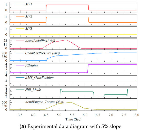
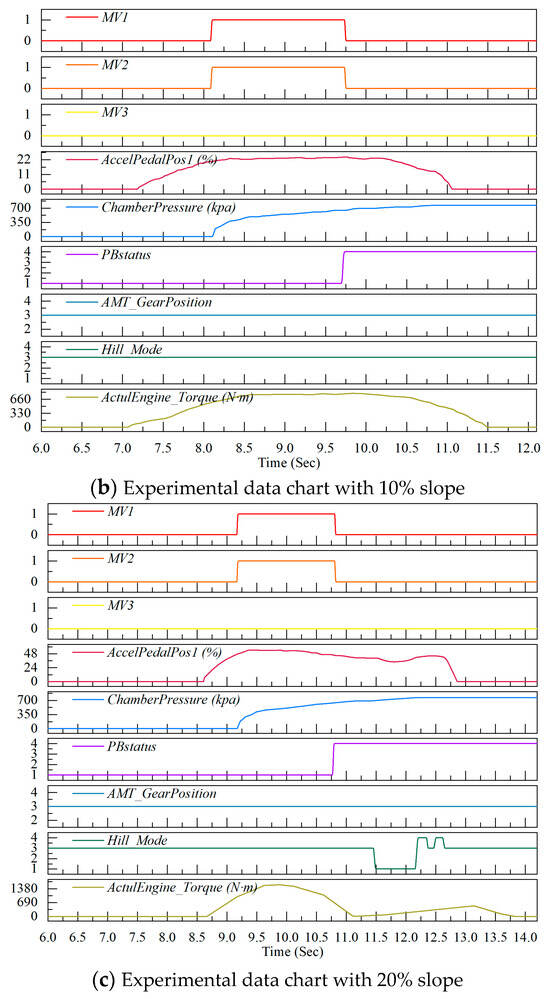
Figure 10.
Hill start conditions on slopes of varying gradients.
During operation, when the accelerator pedal is continuously depressed and the actual torque ActuIEngine_Torque increases to a certain level, the EPB starts to release the parking state. The solenoid valves MV1 and MV2 are energized, causing the chamber pressure to rise. Then, the vehicle starts moving, the working state of the EPB changes to “released”, and the SSV valve is pressed down by the chamber pressure.
The experimental results show that under the uphill starting conditions of 5%, 10%, and 20% slopes, the EPB system can automatically release the parking state according to the change of engine torque and the setting logic and realize the smooth start of the vehicle through the cooperation of solenoid valve action and chamber pressure change.
4.2.4. Downhill Starting Condition
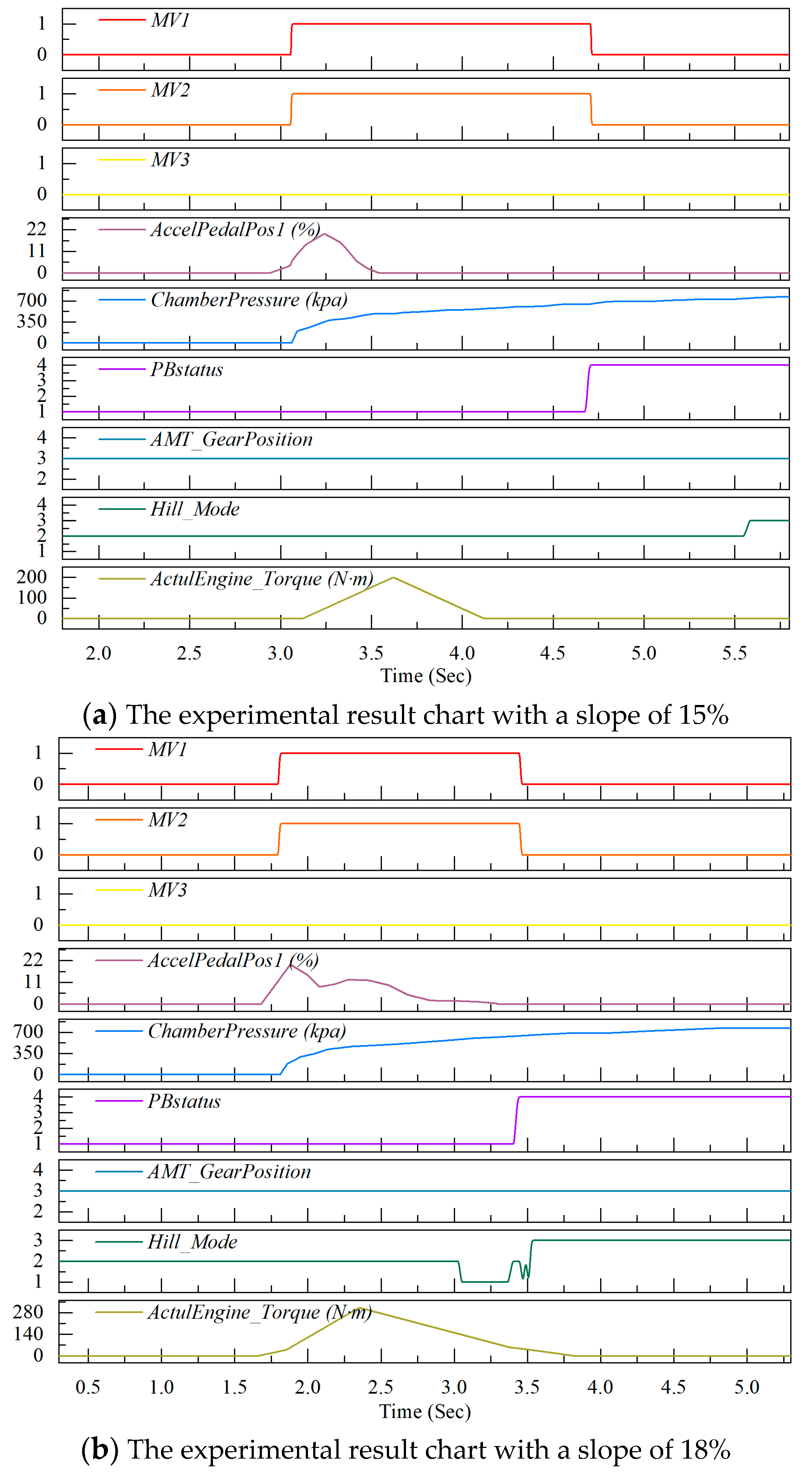
This experiment tests the automatic release condition of the vehicle at the beginning of a downhill incline. After consideration, 15% and 18% slopes are selected to simulate the road conditions of a gentle slope and steep slope, respectively, to obtain key performance data such as vehicle power transmission, braking efficiency, and driving stability, as well as to provide support for vehicle dynamics research.
The experimental results of the starting conditions at different downhill slopes are shown in Figure 11. Under the starting conditions on downhill slopes with gradients of 15% and 18%, the initial gear of the vehicle is AMT Gear Position = 3 (forward gear), the chamber pressure is 0 kPa, the accelerator pedal is not depressed (AccelPedalPos1 = 0), the EPB (electronic parking brake) is in the parking state, and the vehicle is in the downhill mode on the ramp. During operation, when the accelerator pedal is gently depressed, the EPB starts to execute the parking release. The solenoid valves MV1 and MV2 operate, the chamber pressure rises, the vehicle starts moving, the working state of the EPB changes to released, and the SSV valve is pressed downward by the chamber pressure.
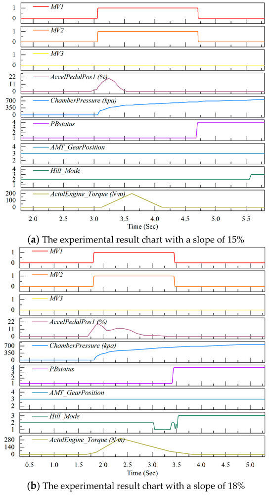
Figure 11.
Starting conditions of different downhill slopes.
The experimental results show that under the downhill starting conditions of 15% and 18% slopes, the EPB system can automatically release the parking state when stepping on the acceleration pedal according to the setting logic and realize the vehicle start with the cooperation of solenoid valve action and chamber pressure change.
5. Conclusions
In this paper, a new bistable electronic parking brake system is designed. By leveraging the SSV valve and multiple solenoid valves, it precisely controls the air path using compressed air to achieve braking and release. Meanwhile, a road experimental test platform is built, and the JAK tractor is selected as the experimental prototype for road tests under full-load conditions in different typical working scenarios. The results show that the manual parking/release function is stable and reliable. The average deceleration during emergency braking is approximately 2.1 m/s2, and its performance exceeds the national standard. Under the conditions of ramp starts and downhill starts with different slopes, the system can automatically release the parking state according to the set logic, ensuring the smooth start of the vehicle, which effectively verifies the performance and reliability of the new bistable EPB system. The new bistable electronic parking brake system designed in this paper has a reference value for solving the braking problems of commercial vehicles under typical working conditions, improving vehicle braking safety, and providing a reference for the optimization and upgrading of subsequent electronic parking brake systems, as well as the development of new systems.
Author Contributions
Conceptualization, F.C. and X.S.; Methodology, B.Q., X.S. and Z.F.; Software, Z.F., G.C. and L.M.; Validation, F.C. and Q.H.; Formal analysis, Z.F. and L.Y.; Investigation, L.Y.; Resources, F.C., B.Q. and Z.F.; Data curation, Z.F., B.Q., Q.H. and L.M.; Writing—original draft, X.M. and L.Y.; Writing—review and editing, F.C., G.C. and X.S.; Visualization, L.Y.; Project administration, F.C., X.S. and Z.F.; Funding acquisition, F.C. and X.S. All authors have read and agreed to the published version of the manuscript.
Funding
This research was supported by the research and application of key components for new energy vehicles and research and application of wire-controlled steering system for new energy vehicles (2022C01241) from the Fellowship of the China Postdoctoral Science Foundation (2022M712835).
Data Availability Statement
Data are contained within the article.
Acknowledgments
The authors would like to thank the useful comments and constructive suggestions from the handling editor and anonymous reviewers.
Conflicts of Interest
Author Feng Chen, Zhiquan Fu, Baoxiang Qiu, Gangqiang Chen, Leyong Mao, Qijiang He, was employed by the company Zhejiang VIE Science & Technology Co., Ltd. The remaining authors declare that the research was conducted in the absence of any commercial or financial relationships that could be construed as a potential conflict of interest.
References
- Sumantran, V.; Fine, C.; Gonsalvez, D. Faster, Smarter, Greener: The Future of the Car and Urban Mobility; MIT Press: Cambridge, MA, USA, 2017. [Google Scholar]
- Wang, B.; Guo, X.; Zhang, C.; Xiong, Z.; Zhang, J. Modeling and control of an integrated electric parking brake system. J. Frankl. Inst. 2015, 352, 626–644. [Google Scholar] [CrossRef]
- Davidyan, G.; Bortman, J.; Kenett, R.S. Development of an Operational Digital Twin of a Locomotive Parking Brake for Fault Diagnosis. Sci. Rep. 2023, 13, 17959. [Google Scholar] [CrossRef] [PubMed]
- Soliman, A.M.E.; Kaldas, M.M.; Soliman, A.M.A.; Huzayyin, A.S. Vehicle Braking Performance Improvement via Electronic Brake Booster. SAE Int. J. Veh. Dyn. Stab. NVH 2024, 8, 63–79. [Google Scholar] [CrossRef]
- Tian, B.; Li, L.; Liao, Y.; Lv, H.; Wang, X.; Hu, Z.; Sun, Y.; Qu, W. An Economical Multilevel Backup Strategy for Electro-Hydraulic Braking System by Integrating Driving and Electronic Parking Brake Systems. SAE Int. J. Veh. Dyn. Stab. NVH 2024, 8, 543–554. [Google Scholar] [CrossRef]
- Wang, B.; Guo, X.; Zhang, W.; Chen, Z. A study of an electric parking brake system for emergency braking. Int. J. Veh. Des. 2015, 67, 315–346. [Google Scholar] [CrossRef]
- Heydrich, M.; Ivanov, V.; Bertagna, A.; Rossi, A.; Mazzoni, M.; Bücner, F. Hardware-in-the-loop testing of a hybrid brake-by-wire system for electric vehicles. SAE Int. J. Veh. Dyn. Stab. NVH 2022, 6, 477–487. [Google Scholar] [CrossRef]
- Wang, B.; Zhang, S.; Ji, W.; Gao, Y. Electronic parking algorithm of new energy vehicle on slope based on FMPC. Heliyon 2023, 9, e21587. [Google Scholar] [CrossRef] [PubMed]
- Wu, L.; Wang, H.; Pi, D.; Wang, E.; Wang, X. Hill-start of distributed drive electric vehicle based on pneumatic electronic parking brake system. IEEE Access 2020, 8, 64382–64398. [Google Scholar] [CrossRef]
- Peng, P.; Wang, H.; Wang, X.; Wang, W.; Pi, D.; Jia, T. Research on the Hill Start Assist of Commercial Vehicles Based on Electronic Parking Brake System. J. Mech. Eng./Stroj. Vestn. 2019, 65, 50. [Google Scholar]
- Soudagar, I.A.K.; Tota, P.D. Modelling and Simulation of Electro-Pneumatic Parking Brake System for Real Time Estimation of Pressure Inside Parking Brake Chamber. 2022. Available online: https://odr.chalmers.se/items/268f3f40-d299-4eaa-846d-ceef0cb76152 (accessed on 3 March 2025).
- Jeon, K.; Hwang, H.; Choi, S.; Hwang, S.; Choi, S.B.; Yi, K. Development of a Fail-safe Control Strategy Based on Evaluation Scenarios for an FCEV Electronic Brake System. Int. J. Automot. Technol. 2012, 13, 10671075. [Google Scholar] [CrossRef]
- Ma, S.; Zhou, X.; Jiang, H.; Li, A.; Han, M.; Tao, T.; Xu, G. A novel intelligent fault diagnosis method for commercial vehicle pneumatic braking system. Proc. Inst. Mech. Eng. Part D J. Automob. Eng. 2024, 09544070241249507. [Google Scholar] [CrossRef]
- Liu, P.; Wang, T.; Chai, Z.; Liu, C.; Zhu, X. Optimized parking control for electric vehicle driven by switched reluctance motor. IEEE Access 2023, 11, 130719–130732. [Google Scholar] [CrossRef]
- Schlimme, H.C.; Henze, R. Brake-by-wire system redundancy concept for the double point of failure scenario. SAE Int. J. Veh. Dyn. Stab. NVH 2023, 7, 329–341. [Google Scholar] [CrossRef]
- Bagherpour, S.; Akbarzadeh, M.R.; Mouloodi, S. Sensitivity analysis of heavy vehicle air brake system to air leakage. SAE Int. J. Commer. Veh. 2020, 14, 69–83. [Google Scholar] [CrossRef]
- Jo, T.; Park, I.; Lee, J.; Yoon, J.; Lee, J.; Kim, H. A fault diagnosis and fault-tolerant anti-lock brake system control for actuator stuck failures in braking system in autonomous vehicles. IEEE Trans. Transp. Electr. 2024, 11, 188–203. [Google Scholar] [CrossRef]
- Henderson, L.; Cebon, D. Design of a pressure modulator using fast-acting bistable valves. Proc. Inst. Mech. Eng. Part C J. Mech. Eng. Sci. 2021, 235, 1133–1147. [Google Scholar] [CrossRef]
- Zhang, Q.; Wang, H.; Gu, W.; Shi, B. Research on matching of control solenoid valve of pneumatic electronic parking brake system. Sci. Technol. Eng. 2016, 16, 99–104+110. [Google Scholar]
- Braeuer, T. Hillholder Assistance System Having a Variable Condition for Releasing the Brake. U.S. Patent 20100262349 A1, 14 October 2010. [Google Scholar]
- Sho, M.; Park, K.; Park, M.B.; Kim, M. Development of a Fail-Safe Control Strategy for Electro-Mechanical Brake System; SAE Technical Paper 2013-01-0055; SAE International: Warrendale, PA, USA, 2013. [Google Scholar]
- GB 12676-2014; Technical Requirements and Test Methods for Braking Systems for Commercial Vehicles and Trailers. Standardization Administration of China: Beijing, China, 2014.
Disclaimer/Publisher’s Note: The statements, opinions and data contained in all publications are solely those of the individual author(s) and contributor(s) and not of MDPI and/or the editor(s). MDPI and/or the editor(s) disclaim responsibility for any injury to people or property resulting from any ideas, methods, instructions or products referred to in the content. |
© 2025 by the authors. Licensee MDPI, Basel, Switzerland. This article is an open access article distributed under the terms and conditions of the Creative Commons Attribution (CC BY) license (https://creativecommons.org/licenses/by/4.0/).