


Abstract
In this paper, an event-triggered (ET) control strategy for a flapping-wing robot aircraft system (FWRA) based on high-gain observers is investigated. To solve the vibration problems of bending deformation and torsional deformation that may be encountered in an FWRA during flight, a novel control method is proposed. Firstly, high-gain observers are used to accurately estimate the unmeasured states of the system, and then output feedback ET controllers are designed by combining ET mechanisms. These controllers can effectively suppress the vibrations and ensure the stability of the system, and the occurrence of the Zeno phenomenon is effectively prevented, while the communication burden is reduced. Finally, the simulation results verify the effectiveness of the proposed method.
1. Introduction
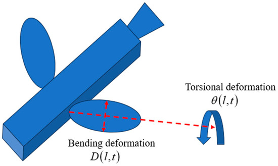
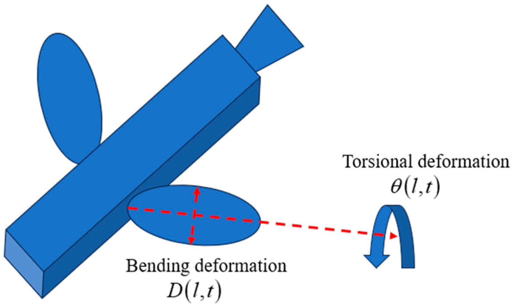
A flapping-wing robot aircraft system (FWRA) is an advanced aerial vehicle that integrates many technologies in bionics, aerodynamics, mechanical manufacturing and intelligent control. The system imitates the flight mode of birds and insects in nature [1,2,3] and generates lift and thrust by flapping its wings to realize flight tasks in complex environments. Compared with a traditional fixed-wing structure, the flexible wing structure has significant advantages, such as a light weight, high flexibility, high energy efficiency and low noise [4,5,6], and has great application potential in military reconnaissance, environmental perception, disaster relief and other fields [7,8]. A 3D model of an FWRA is shown in Figure 1. However, FWRAs often experience significant bending and torsional vibrations during flight due to their complex mechanical structure and high-speed flapping action. These vibrations not only affect the stability and control accuracy of the aircraft but may also cause damage to its structure and shorten its service life. Therefore, vibration control becomes one of the key challenges in the design of FWRAs.
Figure 1.
The 3D model of an FWRA.
Flexible structures include flexible manipulators [9,10,11], flexible beams [12,13,14], flexible risers [15,16,17], etc. Effective vibration suppression in flexible structures is a current research focus. For example, in [18], the problem of vibration control design for an overhead crane system is solved. In [19], a consensus tracking control strategy is proposed for multi-agent systems. The designed controller not only can ensure that the angle and displacement of all agents reach a consensus but can also suppress the elastic deformation and the speed of deformation of each agent. This paper focuses on the vibration control of FWRAs.
In practical engineering, some control signals are not directly measurable due to the influence of noise, and this may result in an inability to accurately control the system [20,21]. In order to solve this problem, observers have come into being. Among these, high-gain observers stand out among the many observers with their unique advantages. Currently, there are many studies on high-gain observers. For example, in [22], a set of high-gain observers is designed to replicate the unmeasurable system states when a system’s states cannot be directly measured. In [23], an enhanced high-gain observer is designed to monitor the posture of a needle tip. In this paper, inspired by the above, high-gain observers are used to estimate the unmeasured states of the system.
In increasingly complex control systems and communication networks, the traditional data transmission and control strategies based on time periodicity are facing many challenges, such as low resource utilization, aggravated network congestion and system response delays. In order to solve these problems, event-triggered (ET) control emerges, as required by the times, and has gradually received extensive attention and research. Compared to traditional periodic sampling, ET control is capable of reducing communication transmissions while maintaining the system’s performance effectively [24,25,26]. At present, many research results have been obtained on ET control. For example, in [27], the communication resources were saved by introducing a relative-threshold-based ET strategy. In [28], an ET output feedback inversion boundary controller is proposed for a 2 × 2 hyperbolic ODE system which determines the trigger time to update the continuous-time control law obtained. In [29], through the design of internal dynamic variables, the communication transmission frequency and control consumption are effectively reduced.
In summary, it is important to develop an output feedback ET controller for an FWRA. The main contributions of this paper are as follows:
- (1)
- The works [30,31,32] assumed that all system states can be accurately obtained through measurements, and their studies were carried out on this basis. However, in practical engineering, some control signals are difficult to detect directly due to the influence of noise. This may lead to inaccurate system control. To overcome this challenge, this paper uses high-gain observers to estimate the boundary states of the system.
- (2)
- ET control can effectively lighten the computational burden and communication requirements of the controller and improve the energy efficiency of the system. This control method has received extensive attention and was utilized in [33,34]. However, although ET control has made remarkable achievements in many fields, there is still a lack of relevant research in the specific field of FWRAs. How to optimize the control performance of FWRAs and reduce their resource consumption through an ET mechanism has become a key problem to solve urgently. Therefore, this paper proposes output feedback ET controllers with which the vibrations of an FWRA are effectively suppressed, while communication resources are saved and the communication burden is reduced.
The rest of this paper is organized as follows: Section 2 presents a dynamic model of the FWRA and the reasonable assumptions and control objectives of this paper. Section 3 outlines the design method for the output feedback ET controllers and analyzes the stability of the closed-loop system. In Section 4, simulation results are presented to validate the effectiveness of the proposed approach. The final part presents the main conclusions of the problem studied in this paper.
Notations: To keep this paper concise, the following notations are consistently utilized, , , , , , , where represents the partial derivative; and represent the first- and second-order partial derivatives of with respect to ; and , , , and represent the first-, second-, third-, and fourth-order partial derivatives of with respect to . In addition, parts of the variables and are omitted, which means that , , and are simplified into , , and , respectively.
2. System Modeling and Preliminaries
The FWRA studied in this paper is characterized by the following PDE dynamic model system for [2]:
where is the length of the flapping wing; represents the mass per unit of span; the polar moment of inertia, denoted by , characterizes the resistance of the wing’s cross-section to torsional or rotational deformation; represents the bending stiffness; represents the torsional stiffness; represents the distance between the wing’s center of mass and its shear center; can be referred to as the distance between the aerodynamic center and the shear center; the term denotes the Kelvin–Voigt damping coefficient; the wing tip is denoted by ; and and correspond to the boundary control inputs that influence the bending and torsional deformations, respectively. Along the flexible wing, a distributed disturbance exists, which is denoted by .
Assumption 1
([30]). For an unknown time-varying distributed disturbance , we suppose the constant is such that it satisfies , .
Control objectives: In this paper, combined with ET mechanisms, output feedback ET controllers for an FWRA are designed to achieve the following objectives: (1) Output feedback ET controllers are proposed to effectively suppress the vibration of bending and torsional deformation of the FWRA. (2) We make sure that all signals are bounded. (3) The Zeno phenomenon is avoided.
3. Controller Design and Stability Analysis
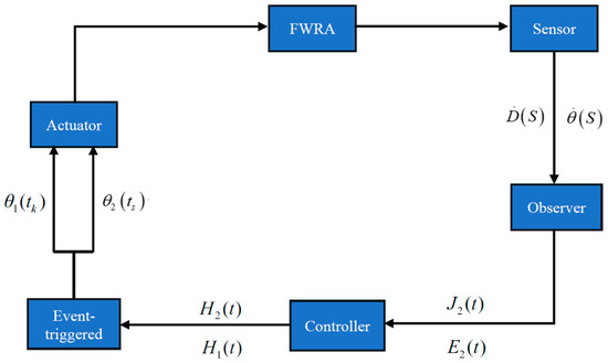
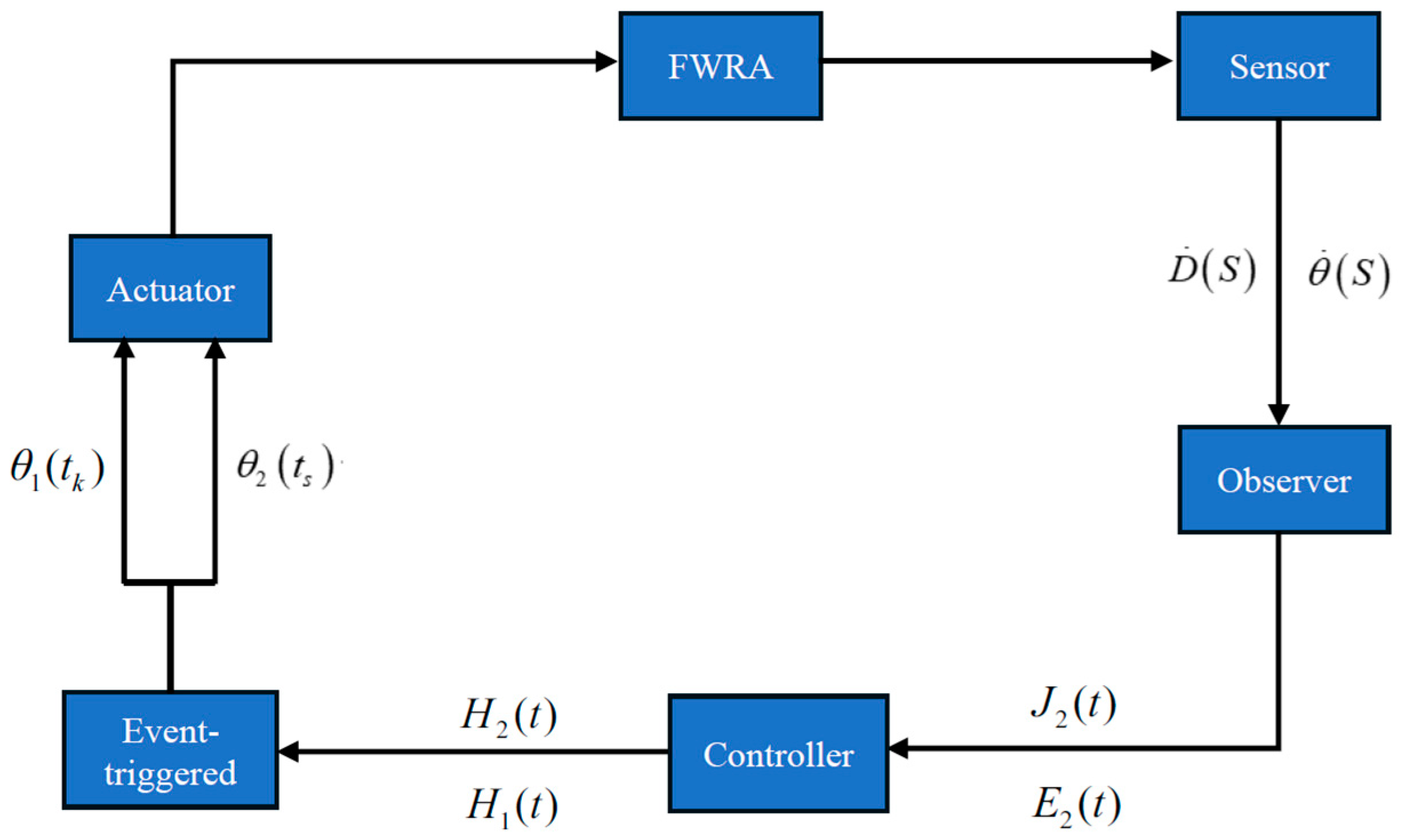
To attain the control objectives, output feedback ET controllers are designed, and the stability of the closed-loop system is analyzed. Figure 2 shows a diagram of the control framework, which clearly shows the control idea in this paper.
Figure 2.
A diagram of the control framework.
3.1. Design of the Output Feedback ET Controllers
The boundary signals and can be measured using sensors, and the backward difference method can be used to obtain the signals and . The presence of noise in the actual system leads to the amplification of the measurement noise generated by the sensors during the calculation of the differentiation, which in turn affects the controller implementation. To mitigate the influence of noise on the system’s signal acquisition, high-gain observers are employed to estimate the unmeasurable states and of the system. Before embarking on the design process, it is essential to consider the following critical lemma.
Lemma 1
([20]). Suppose that we have a system with an output , and its first derivatives are bounded by , where are positive constants; then, the following linear system is considered:
where is any small positive constant, and the parameters , for , are chosen such that the polynomial is a Hurwitz polynomial. We can observe the following property:
where , with denoting the derivative of . In addition, the constants and are such that , and one has , where denotes the standard Euclidean norm.
By applying Lemma 1, it is clear that converges to , which is the derivative of ; this implies that converges to zero due to the high gain . Consequently, it is appropriate to select as an observer to estimate the output signals up to the -order derivative.
Define and ; the estimate of the state is designed as
where and the estimate error are designed as
In the same manner, we define and , and the estimate of the state is designed as
where and the estimate error are designed as
Based on the utilization of the high-gain observers, the following ET mechanisms are proposed for the controller design:
where the intermediate control signals are denoted as and , and the timing for updating the control input and is represented by and , respectively. When ET mechanisms (13) and (15) are triggered, the current times are immediately recorded as and , and the control inputs and at this time are sent to the actuator. , , and are unknown positive constants. and are the measurement errors, and are the control laws to be designed.
There are continuous time-varying coefficients and which satisfy [32]
where
In conjunction with the ET strategies provided, the output feedback ET controllers are formulated as follows:
where and are constants.
3.2. The Stability Analysis
To achieve the control objectives, the Lyapunov function is chosen as
where
Let us create a new function
From (22) and (24), one acquires
where , .
Thanks to Lemma 2 from [35] and using Young’s inequality, (23) is written as follows:
where .
From (25) and (26), it is demonstrated that possesses both an upper bound and a lower bound, i.e.,
We select suitable parameters that satisfy the following two inequalities: .
Then taking the derivative of (21), one has
First of all, taking the derivative of , one has
To facilitate the calculation, we define the following symbols , , and the analysis of and is as follows.
After substituting (1) into , one obtains
Integrating (30) by parts and applying Young’s inequality, Lemma 2 from [35], and boundary condition (4), (30) can be represented in the following manner:
After substituting (2) into , one obtains
The same algorithm as in , (32), can be represented in the following manner:
After integrating systems (31) and (33) into (29), the following can be obtained:
where are constants.
The derivative of with respect to the time can be obtained as
For ease of description, the symbols , are defined, and the analysis of and is as follows:
After substituting (1) into , one obtains
By integrating (36) by parts and utilizing Young’s inequality, Lemma 2 from [35], and boundary condition (4), it is obtained that
After substituting (2) into , one obtains
The same algorithm as in , (38), can be expressed in the following manner:
After putting systems (37) and (39) into (35), the following can be obtained:
where are positive constants.
Substituting (34) and (40) into (28) yields
We select suitable parameters to meet the following conditions:
To facilitate the analysis, and represent and , respectively. The analysis of and is as follows.
Substituting (16) and (19) into , is rewritten as follows:
Using Young’s inequality, (43) can be written as follows:
Similarly, Substituting (16) and (20) into , is rewritten as follows:
Using Young’s inequality, (45) can be written as follows:
After substituting (44) and (46) into (41) and rearranging, (41) can be written as
where , , and and are positive constants.
The remaining pertinent parameters adhere to the following inequalities:
Therefore, an upper bound for exists, i.e.,
where .
Theorem 1.
For the FWRA (1)–(5) and given that the initial conditions are bounded, thanks to Lemma 2 in [35], the ET mechanisms (12)–(15), and the output feedback ET controllers (19)–(20), we achieve the following:
- (1)
- All of the signals are bounded;
- (2)
- The vibrations of bending deformation and torsional deformation in the FWRA are effectively suppressed;
- (3)
- The Zeno phenomenon is avoided.
Proof of Theorem 1.
Multiplying both sides of (49) by and then integrating on , one has
According to Lemma 2 in [35], it follows that
Rewriting (51) and (52), one has
Therefore, as tends to infinity, one has
From (53) and (54), it can be seen that due to the bounded initial values, as approaches infinity, and remain within a small neighborhood. This implies that with , when , the system states and will be close to a small neighborhood around zero.
Since and are bounded , is also bounded. From (22) and (23), it can be seen that , , , and are bounded: . Furthermore, according to the boundedness of the kinetic and potential energy in [2], it can be concluded that the states and are also bounded. Therefore, from (1) and (2), along with the above statements, it can be inferred that and are bounded . Thus, all of the signals are bounded: .
We can see from (55) and (56) that and are bounded; therefore, the vibrations of bending deformation and torsional deformation in the FWRA are effectively suppressed.
Based on the above analysis, it is clear that by appropriately selecting the control parameters, the state variables of the FWRA can converge to the desired values, thereby ensuring the stability of the closed-loop system.
Next, this paper demonstrates in detail that the proposed control scheme can effectively avoid the Zeno phenomenon, which is proven as follows:
Considering , , , and , from (19) and (20), it can be further deduced that and exhibit continuity as a function of and , respectively. Therefore, positive constants and must exist which satisfy , and , and . Again, here, positive constants and mist exist that permit and , and one can find and .
According to the above analysis, the Zeno phenomenon is avoided effectively.
Hence, the proof for Theorem 1 is completed. □
4. The Simulation Example
In this section, the finite difference method is used to simulate the FWRA, and the effectiveness of the designed output feedback ET controllers (19) and (20) is verified using simulation examples.
The parameters for the FWRA (1)–(5) are provided as follows: , , , , , , , and . In the simulation, the parameters related to the output feedback ET controllers (19) and (20) are designed: , , , , , and . The observer’s parameters are , , , and . The distributed disturbance .
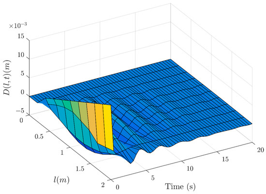
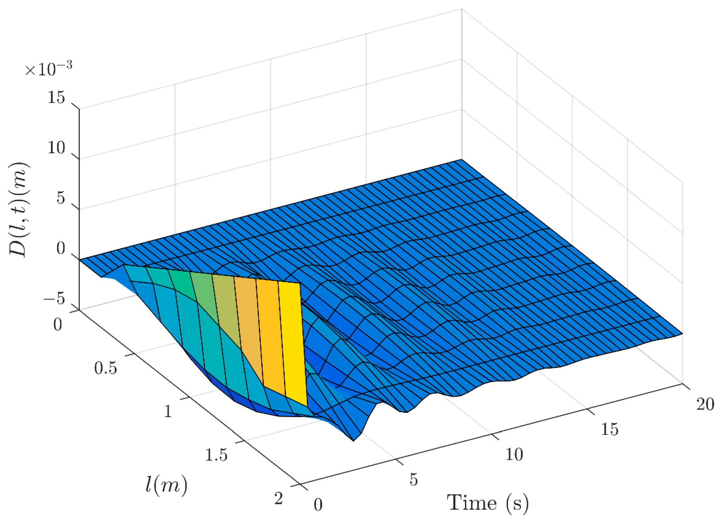
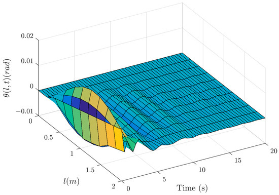
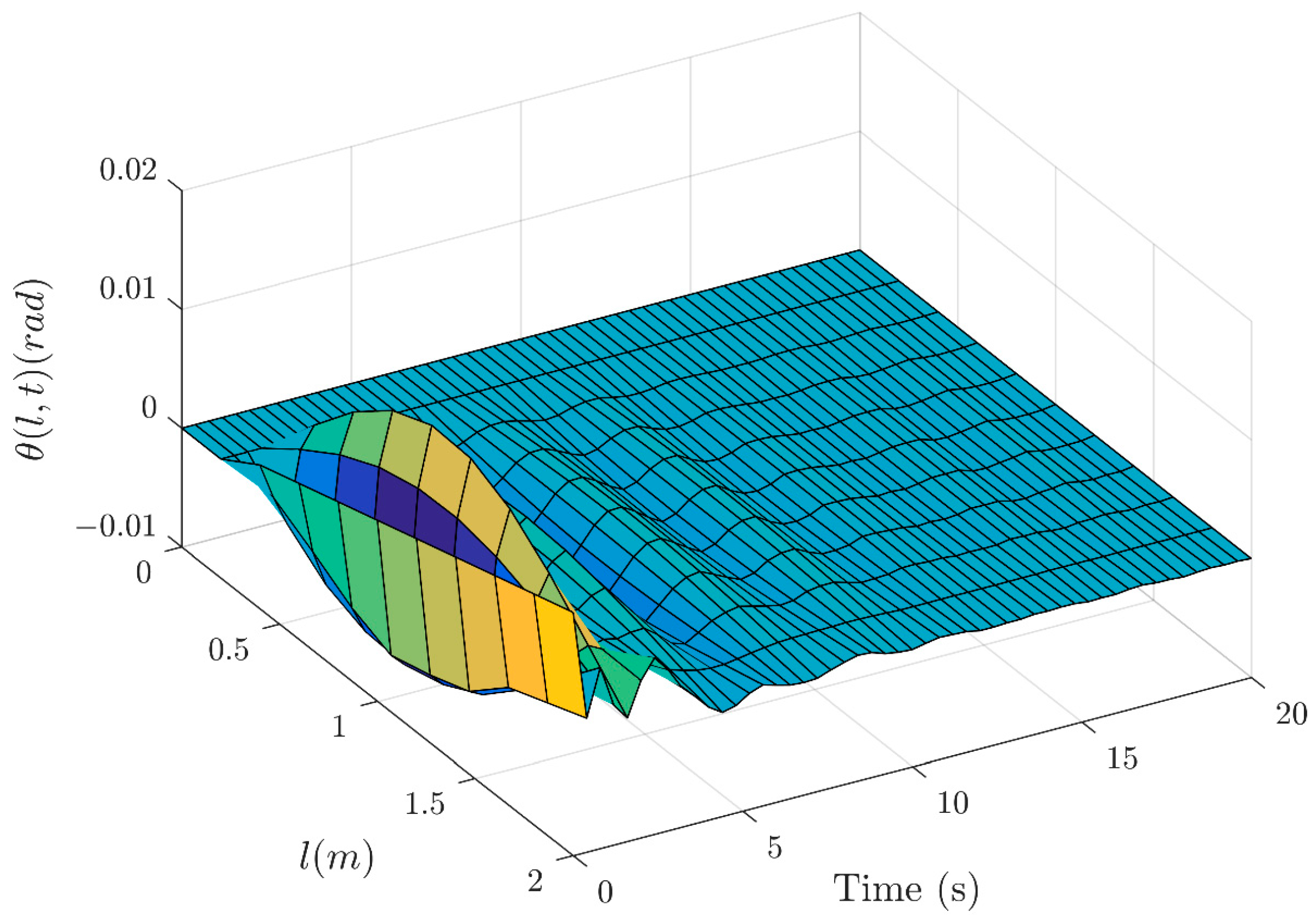
Considering the given initial conditions , . Here, the simulation results are shown in Figure 3, Figure 4, Figure 5, Figure 6, Figure 7, Figure 8, Figure 9 and Figure 10, which provide a visual representation of our findings.
Figure 3.
The bending deformation of the wing with control.
Figure 4.
The torsional deformation of the wing with control.
Figure 5.
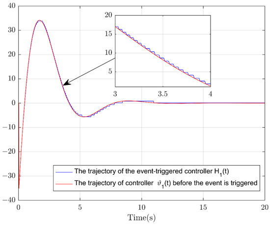
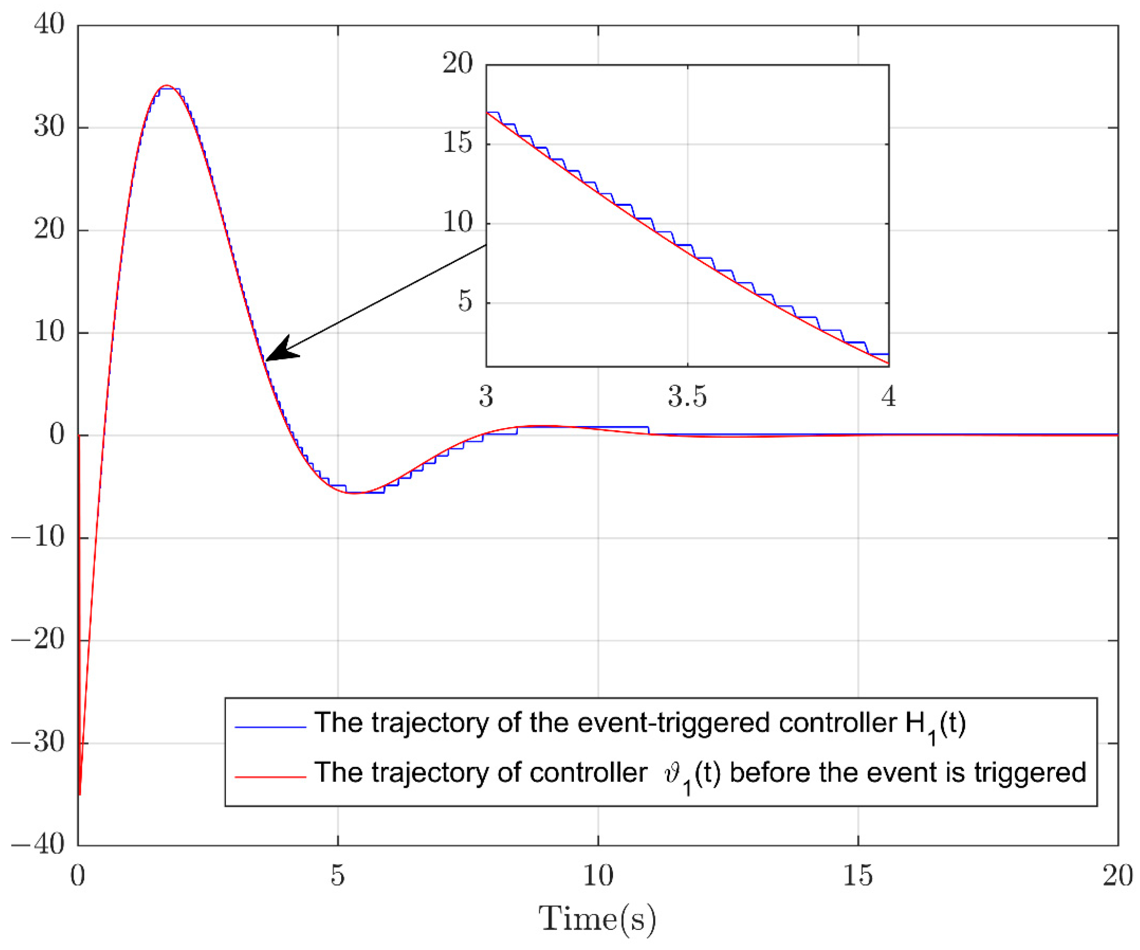
The trajectory followed by the output feedback ET controller and the trajectory of the controller before the event is triggered.
Figure 6.
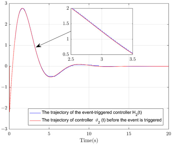
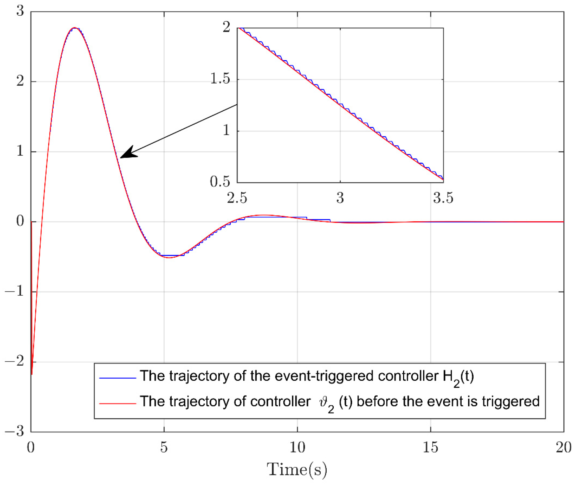
The trajectory followed by the output feedback ET controller and the trajectory of the controller before the event is triggered.
Figure 7.
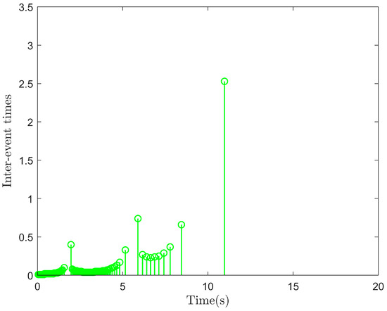
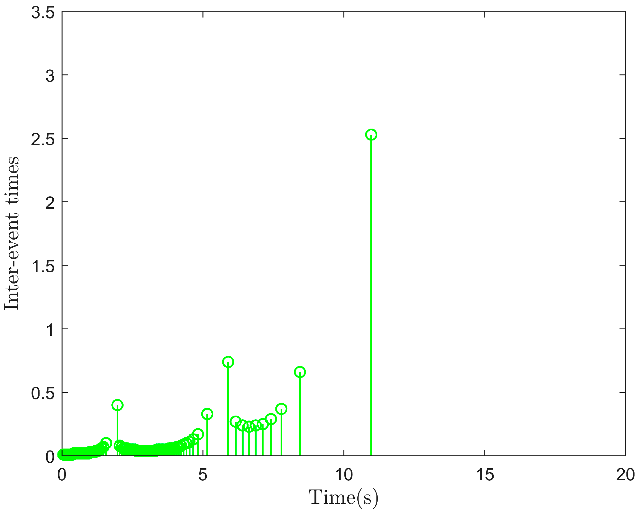
The control triggering the event.
Figure 8.
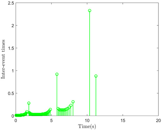
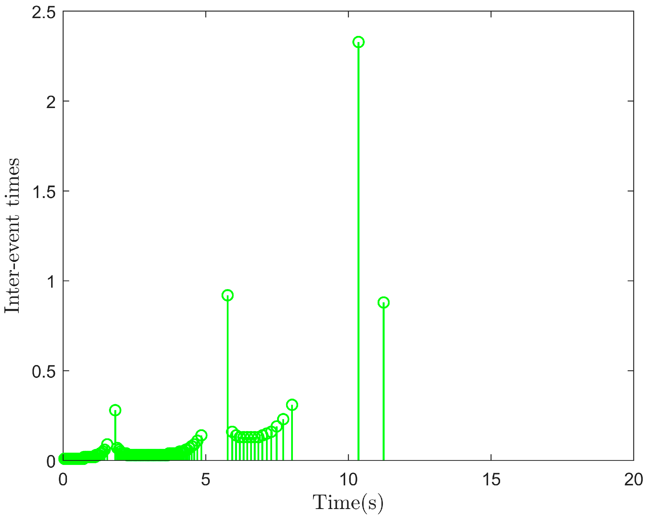
The control in triggering the event.
Figure 9.
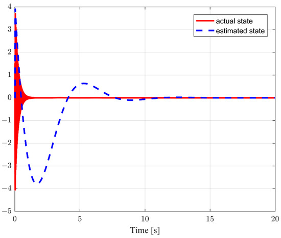
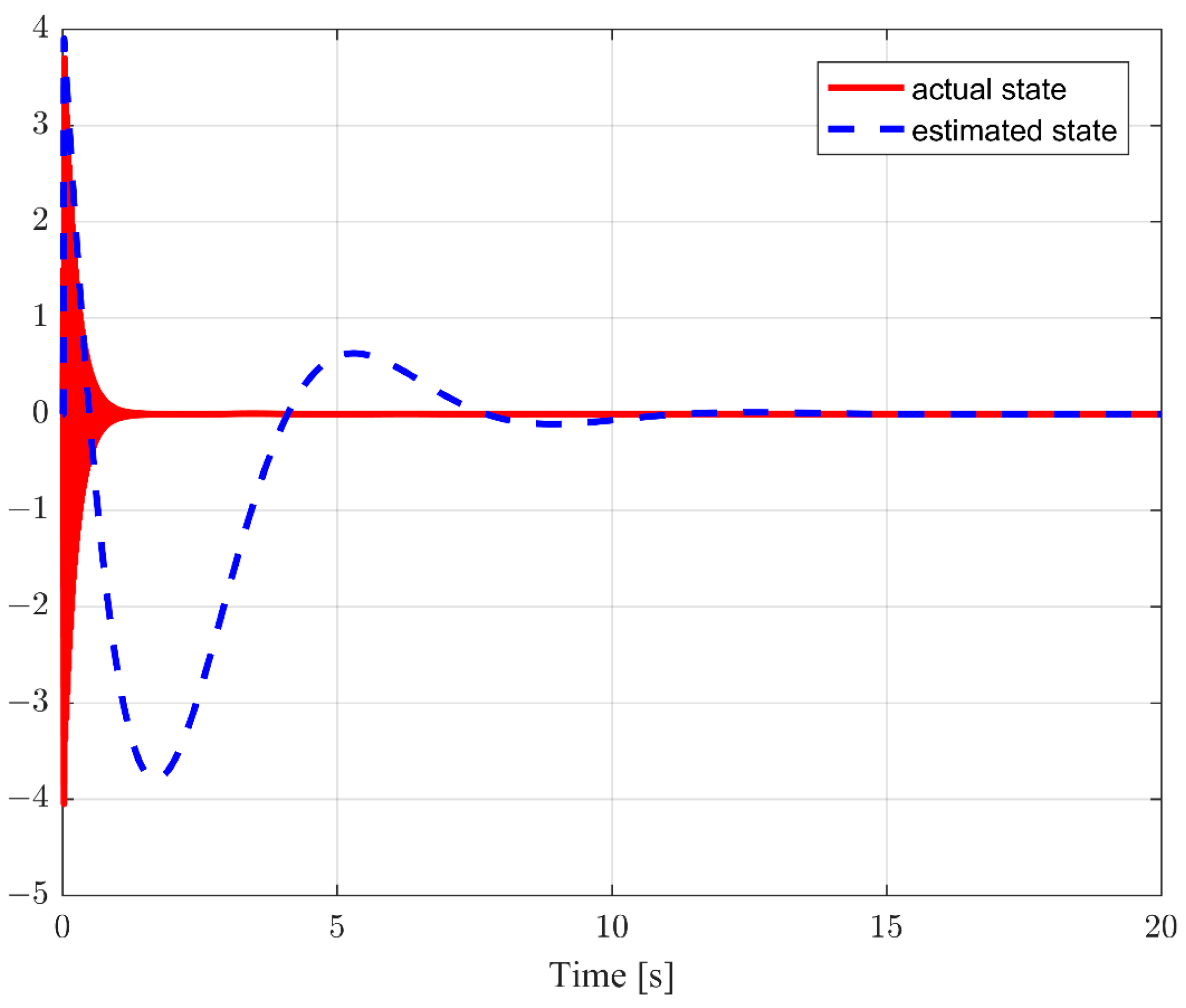
States : the actual state (solid line) and the estimated state (dotted line).
Figure 10.
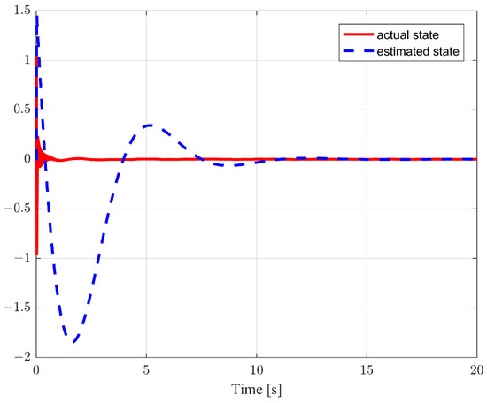
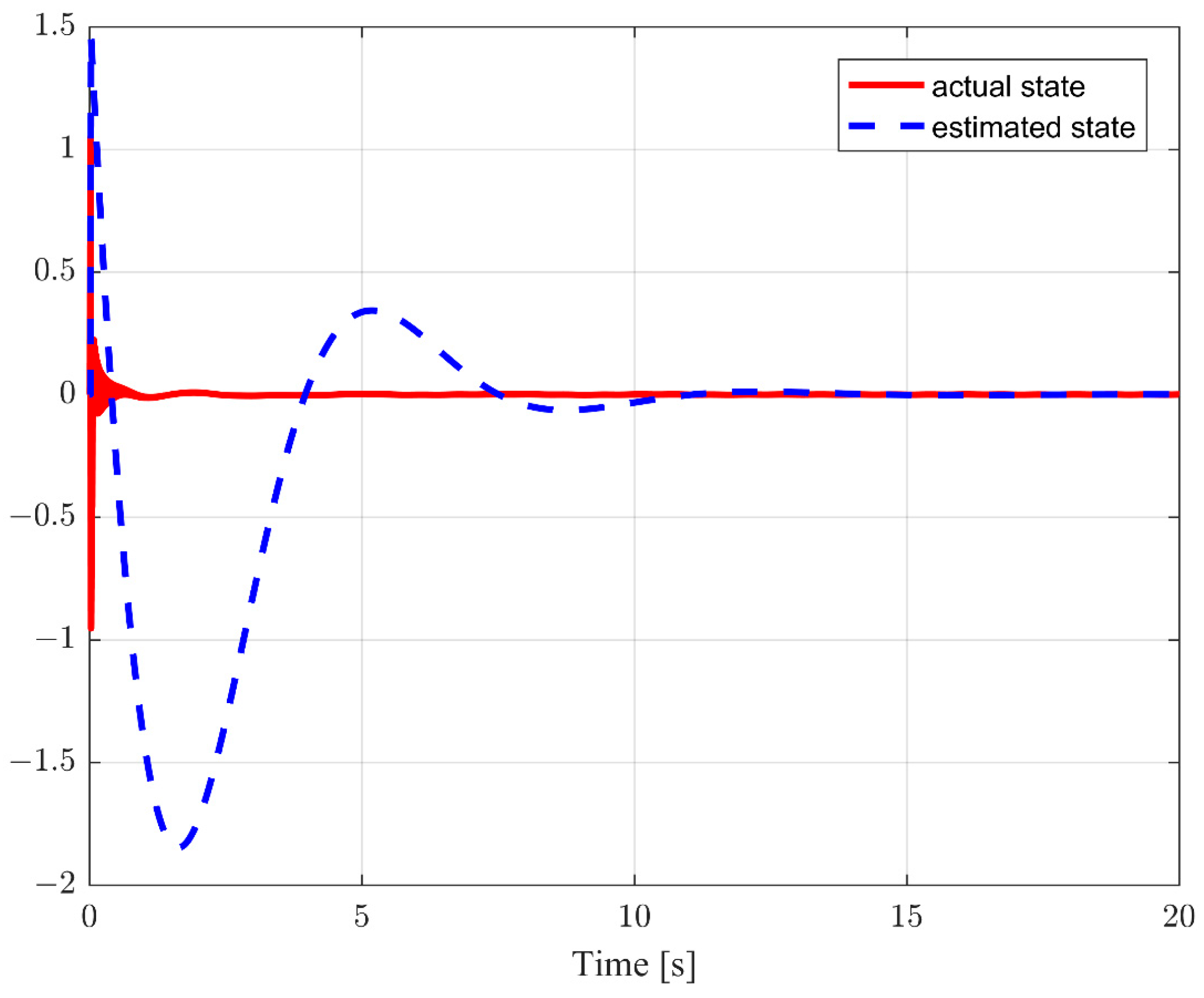
States : the actual state (solid line) and the estimated state (dotted line).
As depicted in Figure 3 and Figure 4, the bending deformation and the torsional deformation of the FWRA under output feedback ET control ultimately converge to zero. Therefore, the output feedback ET control scheme proposed in this paper is successful in suppressing vibrations. That is, (1) and (2) in the control objectives are verified in the simulation results.
Figure 5, Figure 6, Figure 7 and Figure 8 provide valuable insights into the control inputs and of the FWRA, as well as the ET frequency. Figure 5 and Figure 6 show a comparison of the trajectories of the output feedback ET controllers and the trajectories of the controllers before the event is triggered. It can be seen from the figures that the trajectories of the ET controllers are step-like, while the trajectories of the controllers before the ET mechanisms are smooth curves. Therefore, the frequency of transmission of the control values is significantly reduced when utilizing the ET controllers proposed in this paper. The presence of ET trigger nodes is evident in Figure 7 and Figure 8. Therefore, the ET control scheme presented in this paper effectively lowers the redundancy, reduces the reliance on frequent communication channels, and greatly alleviates the communication burden. That is, (3) in the control objectives is verified in the simulation results.
Figure 9 and Figure 10 display the trajectories followed by the actual and estimated values of the system states and , respectively. It can be seen from the figures that the estimated values for and track their actual values well.
In addition, to more intuitively demonstrate the improvement in the efficiency with ET control in terms of the resource utilization compared with traditional time-triggered control, a comparison of the number of ET and time-triggered triggers is made, as shown in Table 1.
Table 1.
Number of ET and time-triggered triggers.
In summary, for an FWRA, the output feedback ET controllers designed can suppress bending deformation and torsional deformation vibrations, the communication burden is effectively reduced, and the working ability of the system is improved in cases of unpredictable system states.
5. Conclusions
In this paper, the vibration suppression problem for an FWRA is studied. High-gain observers are used to estimate certain unmeasured system states. Secondly, the ET mechanism is given, and the output feedback ET controllers are designed based on this ET mechanism to effectively suppress bending and twisting deformation vibrations in FWRAs. In addition, energy consumption for communication is saved, and the Zeno phenomenon is avoided. Finally, the simulation results verify the effectiveness of the proposed control method. However, the ET mechanism proposed in this paper is based on a fixed threshold, which is more conservative. In future work, a dynamic event-triggered technique will be considered to reduce the control consumption further.
Author Contributions
Conceptualization, C.X. and L.T.; methodology, C.X. and H.X.; software, C.X., S.Y. and M.C.; validation, C.X., S.Y. and M.C.; formal analysis, C.X., S.Y. and H.X.; investigation, M.C. and Z.L.; resources, S.Y. and H.X.; data curation, H.X. and Z.L.; writing—original draft preparation, C.X., F.W. and S.Y.; writing—review and editing, L.T., F.W. and Z.L.; visualization, L.T. and F.W.; supervision, L.T.; project administration, L.T.; funding acquisition, L.T. All authors have read and agreed to the published version of the manuscript.
Funding
This work is supported in part by the 2024 Fundamental Research Funding of the Educational Department of Liaoning Province under Grant LJZZ212410154026, and in part by the National Innovation and Entrepreneurship Training Program for Undergraduate under Grant 202410154006, and in part by the National Natural Science Foundation of China under Grant 62273171.
Data Availability Statement
In terms of the data availability, if a researcher requires data from this article, the corresponding author can provide the simulation data.
Conflicts of Interest
The authors have declared no conflicts of interest.
References
- Pan, E.; Liang, X.; Xu, W.F. Development of vision stabilizing system for a large-scale flapping-wing robotic bird. IEEE Sens. J. 2020, 20, 8017–8028. [Google Scholar] [CrossRef] [Scilit]
- He, W.; Mu, X.X.; Chen, Y.N.; He, X.Y.; Yao, Y. Modeling and vibration control of the flapping-wing robotic aircraft with output constraint. J. Sound Vib. 2018, 423, 472–483. [Google Scholar] [CrossRef] [Scilit]
- Gao, H.J.; He, W.; Zhang, Y.M.; Sun, C.Y. Adaptive finite-time fault-tolerant control for uncertain flexible flapping wings based on rigid finite element method. IEEE Trans. Cybern. 2021, 52, 9036–9047. [Google Scholar] [CrossRef] [Scilit]
- Pan, E.; Xu, H.; Yuan, H.; Peng, J.Q.; Xu, W.F. HIT-Hawk and HIT-Phoenix: Two kinds of flapping-wing flying robotic birds with wingspans beyond 2 meters. Biomim. Intell. Robot. 2021, 1, 100002. [Google Scholar] [CrossRef] [Scilit]
- He, W.; Mu, X.X.; Zhang, L.; Zou, Y. Modeling and trajectory tracking control for flapping-wing micro aerial vehicles. IEEE/CAA J. Autom. Sin. 2021, 8, 148–156. [Google Scholar] [CrossRef] [Scilit]
- He, W.; Meng, T.T.; He, X.Y.; Sun, C.Y. Iterative learning control for a flapping wing micro aerial vehicle under distributed disturbances. IEEE Trans. Cybern. 2019, 49, 1524–1535. [Google Scholar] [CrossRef] [Scilit] [PubMed]
- Xu, W.F.; Pan, E.; Liu, J.T.; Li, Y.H.; Yuan, H. Flight control of a large-scale flapping-wing flying robotic bird: System development and flight experiment. Chin. J. Aeronaut. 2022, 35, 235–249. [Google Scholar] [CrossRef] [Scilit]
- He, W.; Yan, Z.C.; Sun, C.Y.; Chen, Y.N. Adaptive neural network control of a flapping wing micro aerial vehicle with disturbance observer. IEEE Trans. Cybern. 2017, 47, 3452–3465. [Google Scholar] [CrossRef] [Scilit]
- Zhao, W.; Liu, Y.; Yao, X.Q. Adaptive fuzzy containment and vibration control for multiple flexible manipulators with model uncertainties. IEEE Trans. Fuzzy Syst. 2023, 31, 1315–1326. [Google Scholar] [CrossRef] [Scilit]
- Zhao, Z.J.; Tan, Z.F.; Liu, Z.J.; Efe, M.O.; Ahn, C.K. Adaptive inverse compensation fault-tolerant control for a flexible manipulator with unknown dead-zone and actuator faults. IEEE Trans. Ind. Electron. 2023, 70, 12698–12707. [Google Scholar] [CrossRef] [Scilit]
- Yao, X.Q.; Liu, Y.; Zhao, W. Adaptive boundary vibration control and angle tracking consensus of networked flexible Timoshenko manipulator systems. IEEE Trans. Syst. Man Cybern. Syst. 2023, 53, 2949–2960. [Google Scholar] [CrossRef] [Scilit]
- Jin, F.F.; Guo, B.Z. Lyapunov approach to output feedback stabilization for the Euler–Bernoulli beam equation with boundary input disturbance. Automatica 2015, 52, 95–102. [Google Scholar] [CrossRef] [Scilit]
- Ji, N.; Liu, J.K. Quantized time-varying fault-tolerant control for a three-dimensional Euler–Bernoulli beam with unknown control directions. IEEE Trans. Autom. Sci. Eng. 2023, 21, 6528–6539. [Google Scholar] [CrossRef] [Scilit]
- Cheng, Y.; Wu, Y.; Guo, B.Z. Boundary stability criterion for a nonlinear axially moving beam. IEEE Trans. Autom. Control 2022, 67, 5714–5729. [Google Scholar] [CrossRef] [Scilit]
- Liu, Y.; Wang, Y.N.; Feng, Y.H.; Wu, Y.L. Neural network-based adaptive boundary control of a flexible riser with input dead zone and output constraint. IEEE Trans. Cybern. 2022, 52, 13120–13128. [Google Scholar] [CrossRef] [Scilit]
- He, W.; Sun, C.; Ge, S.Z.S. Top tension control of a flexible marine riser by using integral-barrier Lyapunov function. IEEE/ASME Trans. Mechatron. 2015, 20, 497–505. [Google Scholar] [CrossRef] [Scilit]
- Zhao, Z.J.; He, X.Y.; Ren, Z.G.; Wen, G.L. Boundary adaptive robust control of a flexible riser system with input nonlinearities. IEEE Trans. Syst. Man Cybern. Syst. 2019, 49, 1971–1980. [Google Scholar] [CrossRef] [Scilit]
- Xing, X.Y.; Liu, J.K. PDE modelling and vibration control of overhead crane bridge with unknown control directions and parametric uncertainties. IET Control Theory Appl. 2020, 14, 116–126. [Google Scholar] [CrossRef] [Scilit]
- Li, L.; Liu, J.K. Consensus tracking control and vibration suppression for nonlinear mobile flexible manipulator multi-agent systems based on PDE model. Nonlinear Dyn. 2023, 111, 3345–3359. [Google Scholar] [CrossRef] [Scilit]
- Zhao, Z.J.; Liu, Y.; Luo, F. Output feedback boundary control of an axially moving system with input saturation constraint. ISA Trans. 2017, 68, 22–32. [Google Scholar] [CrossRef] [Scilit]
- Minowa, A.; Toda, M. A high-gain observer-based approach to robust motion control of towed underwater vehicles. IEEE J. Ocean. Eng. 2019, 44, 997–1010. [Google Scholar] [CrossRef] [Scilit]
- Zhang, S.; Liu, R.; Peng, K.X.; He, W. Boundary output feedback control for a flexible two-link manipulator system with high-gain observers. IEEE Trans. Control Syst. Technol. 2021, 29, 835–840. [Google Scholar] [CrossRef] [Scilit]
- Lou, D.K.; Zhang, D.; Liang, H.G. An improved high-gain observer design for flexible needle steering. IEEE Trans. Circuits Syst. II Express Briefs 2023, 70, 3489–3493. [Google Scholar] [CrossRef] [Scilit]
- Lin, N.; Ling, Q. Dynamic periodic event-triggered consensus protocols for linear multiagent systems with network delay. IEEE Syst. J. 2023, 17, 1204–1215. [Google Scholar] [CrossRef] [Scilit]
- Mu, R.; Wei, A.R.; Li, H.T.; Zhang, X.F.; Qi, Y.N. Bipartite output consensus for heterogeneous multi-agent systems with observer-based adaptive event-triggered strategy. IEEE Syst. J. 2023, 17, 6011–6021. [Google Scholar] [CrossRef] [Scilit]
- Song, X.N.; Zhang, Q.Y.; Song, S.; Ahn, C.K. Event-triggered underactuated control for networked coupled PDE-ODE systems with singular perturbations. IEEE Syst. J. 2023, 17, 4474–4484. [Google Scholar] [CrossRef] [Scilit]
- Zhao, X.N.; Zhang, S.; Liu, Z.L.; Wang, J.Y.; Gao, H.B. Adaptive event-triggered boundary control for a flexible manipulator with input quantization. IEEE/ASME Trans. Mechatron. 2022, 27, 3706–3716. [Google Scholar] [CrossRef] [Scilit]
- Wang, J.; Krstic, M. Event-triggered output-feedback backstepping control of sandwich hyperbolic PDE systems. IEEE Trans. Autom. Control 2022, 67, 220–235. [Google Scholar] [CrossRef] [Scilit]
- Cai, G.; Wu, T.; Hao, M.; Liu, H.; Zhou, B. Dynamic event-triggered gain-scheduled H∞ control for a polytopic LPV model of morphing aircraft. IEEE Trans. Aerosp. Electron. Syst. 2025, 61, 93–106. [Google Scholar] [CrossRef] [Scilit]
- Tang, L.; Wang, F. Improving health operation of flapping-wing robotic aircraft systems using event-triggered vibration control technology. IEEE Trans. Consum. Electron. 2025. [Google Scholar] [CrossRef] [Scilit]
- Long, H.; Zhang, P.; Guo, T.; Zhao, J. Fixed-time adaptive fuzzy fault-tolerant control of flapping wing MAVs with wing damage. IEEE Trans. Aerosp. Electron. Syst. 2024, 60, 6594–6607. [Google Scholar] [CrossRef] [Scilit]
- Meng, T.; Guo, B.Z.; Huang, H.; He, W. Iterative learning control for a flexible wing system under iteration-varying disturbances and references. IEEE Trans. Aerosp. Electron. Syst. 2024, 60, 5973–5981. [Google Scholar] [CrossRef] [Scilit]
- Tang, L.; Li, Y.; Liu, Y.J. Adaptive event-triggered vibration control for crane bridge system with trolley. IEEE Trans. Instrum. Meas. 2023, 72, 5504010. [Google Scholar] [CrossRef] [Scilit]
- Gao, S.Q.; Liu, J.K. Event-triggered vibration control for a class of flexible mechanical systems with bending deformation and torsion deformation based on PDE model. Mech. Syst. Signal Process. 2022, 164, 108255. [Google Scholar] [CrossRef] [Scilit]
- Zhao, W.; Sun, H.; Zhao, Z.; Liu, Y. Adaptive fault-tolerant control for flexible manipulators multiagent systems with unknown dead-zones under switching topology. IEEE Trans. Syst. Man Cybern. Syst. 2024, 54, 5412–5421. [Google Scholar] [CrossRef] [Scilit]

Disclaimer/Publisher’s Note: The statements, opinions and data contained in all publications are solely those of the individual author(s) and contributor(s) and not of MDPI and/or the editor(s). MDPI and/or the editor(s) disclaim responsibility for any injury to people or property resulting from any ideas, methods, instructions or products referred to in the content. |
© 2025 by the authors. Licensee MDPI, Basel, Switzerland. This article is an open access article distributed under the terms and conditions of the Creative Commons Attribution (CC BY) license (https://creativecommons.org/licenses/by/4.0/).