1. Introduction
A harmonic drive (HD) is a lightweight transmission mechanism that aligns with the stringent requirements of spacecraft reducers—namely, light weight, compact dimensions, and exceptional precision—while simultaneously offering robust load-bearing capabilities. Consequently, HD has found extensive applications across diverse fields, including robotics, aerospace systems, and medical devices [
1,
2,
3]. A central challenge in HD research stems from the fluctuating deformations of the flexspline (FS), which has rendered the meshing theory and tooth profile (TP) design enduringly complex and pivotal areas of investigation within this domain.
Numerous research methodologies have been developed to investigate the meshing theory of HD, with the envelope method and the kinematic method being the most widely adopted. Shen et al. [
4] established a generalized formula for calculating the conjugate TP of HDs using the envelope method. Building on this, Chen et al. [
5] introduced a precise envelope algorithm that accounts for the elastic deformation of the FS. Recognizing the influence of the wave generator (WG) shape on the relative motion between the FS and the circular spline (CS) [
6], Yang et al. [
7] developed an exact solution method for determining the conjugate TP based on cam profiles. Further advancing the field, Dong et al. [
8] conceptualized the FS and WG as a cam-follower mechanism, providing a rigorous analysis and detailed description of the planar kinematic model of HDs. In a comparative study, Wang et al. [
9] evaluated the kinematic method and the envelope method through the design outcomes of a double circular arc TP, concluding that the envelope method offers superior accuracy.
In the context of TP design, HD initially employed a straight TP to achieve surface-to-surface contact between tooth surfaces. However, this approach failed to account for the circumferential displacement and normal deflection of the tooth rim. Consequently, the technologically mature, involute TP was later widely adopted in HDs. Maiti [
10] demonstrated that an unmodified involute TP could function effectively through the strategic design of the cam. The application and refinement of involute TPs in HDs have been extensively studied [
11,
12]. Nevertheless, involute HDs exhibit poor conjugate characteristics, relying primarily on cusp meshing at the tooth tips to achieve multi-tooth engagement [
4]. This cusp meshing condition, however, tends to disrupt the lubricant film and accelerate tooth wear, rendering the involute profile suboptimal for HD applications. Additionally, while the involute TP of the CS as an internal gear is concave, Ivanov [
13] proposed that the CS TP should be convex based on an analysis of the motion characteristics of the FS teeth. This insight led Ivanov to pioneer the double-arc TP for HDs. Since its introduction, the double circular arc TP has become the dominant approach in HD profile design [
14,
15]. The double circular arc TP not only significantly enhances the conjugate existence interval of HDs by incorporating a convex TP for the CS [
16,
17] but also further improves meshing performance by synchronizing the convex and concave segments of the CS through the utilization of double-conjugate characteristics [
18,
19].
The distinctive characteristics of the double-arc TP have inspired the development and design of novel TPs for HD. Ishikawa et al. [
20] introduced an S-shaped TP directly derived from the halved mapping of the tooth trajectory using the rack approximation method. This innovative profile incorporates both concave and convex segments. Through appropriate TP modifications [
21], which address the interference caused by the normal deflection angle of the FS, the S-shaped TP achieves continuous contact with similarly designed profiles. In a comparative study, Wang et al. [
22] evaluated the double-arc TP designed via the envelope method and the S-shaped TP developed using the rack approximation method, revealing that the S-shaped profile exhibits smaller and more uniform meshing backlash. As a result, both the double circular arc TP and the S-shaped TP have gained widespread adoption in HD applications.
The studies on the double-arc TP and the S-shaped TP demonstrate that it is both logical and effective to consider the motion characteristics of HD and to design TPs directly based on the motion trajectory of gear teeth. Shen et al. [
4] observed that the relative motion trajectory of HD tooth approximates a cycloid. Building on this insight, Le et al. [
23] proposed a cycloidal TP (CTP) composed of epicycloid and inner cycloid segments for HDs. Subsequently, the CTP was further refined through the TP angle design [
24] to eliminate interference within the backlash [
25]. This CTP exhibits theoretical properties akin to those of the double circular arc TP. However, the current CTP is not directly derived from the tooth trajectory, suggesting that there remains significant potential for further optimization and improvement of this profile.
The objective of this paper is to propose a novel construction and design methodology for a CTP tailored for HD, leveraging the combined advantages of trajectory mapping and the envelope method. First, canonical correlation analysis is employed to validate the cycloidal characteristics of the tooth trajectory, followed by the formulation of a CTP equation for HD with variable coefficients. While this equation is inspired by the trajectory mapping method, it is not constrained by its results; instead, the variable coefficients ensure the design flexibility of the CTP. Subsequently, the CTPs of the FS and CS are meticulously designed using the envelope method and the bidirectional conjugate design flow [
16].
In addition to the Introduction section, this article is structured as follows.
Section 2 analyzes the rationality of the CTP, calculates the HD tooth trajectories, and verifies their cycloidal characteristics.
Section 3 constructs the initial cycloidal equations for the TP based on the trajectory mapping relationship and presents the bidirectional conjugate design process for the CTP using the envelope method.
Section 4 provides an example of a TP design, discussing the designed CTP in terms of its conjugate characteristics and backlash distribution.
Section 5 examines the results of the TP design under varying deformation magnitudes. Finally,
Section 6 summarizes the main conclusions of this paper.
2. Rationality Analysis of Cycloid Tooth Profile
When the WG is installed, the FS undergoes deformation, forming a differential meshing relationship with the CS. As the WG rotates, a periodic “meshing in–meshing out” motion is established between the teeth of the FS and CS. This section calculates the tooth trajectory of the HD, extracts the coordinates of several points on the trajectory as the query array s1, and compares it with a reference array s2 extracted from a general cycloid. By employing canonical correlation analysis, the similarity between the tooth trajectory and the general cycloid is verified using the canonical time warping distance. Furthermore, a cycloidal expression for the tooth trajectory is constructed, thereby validating the rationality of applying a CTP to HDs based on tooth trajectory mapping.
2.1. Calculation of Tooth Trajectory
As illustrated in
Figure 1, the neutral circle of the FS with radius
rm undergoes elliptical deformation under the influence of the WG. The coordinate system
S0-
OXY is fixed to the WG, with point
O at the center of rotation and the
Y-axis aligned with the major axis of the WG. The coordinate system
S1-
O1X1Y1 is fixed to the FS tooth, with point
O1 located on the neutral line of the FS and the
Y1-axis aligned with the symmetry line of the tooth (normal at point
O1).
ρ is the polar radius of point
O1. The coordinate system
S2-
OX2Y2 is fixed to the CS tooth, with the
Y2-axis aligned with the symmetry line of the tooth space. The angle
φ represents the initial position of point
O1 relative to the
Y-axis, while
φ1 denotes the angle between their new positions after deformation.
Assuming negligible elongation of the FS under internal deformation forces [
26], the midline non-elongation assumption is approximately satisfied. Consequently, the angles
φ and
φ1 are related as follows:
here, the integral limit
ϕ is equal to the related angle
φ1 of the polar radius
ρ.
φ2 denotes the angle between the symmetry line of the CS tooth space and the
Y-axis.
here,
z1 and
z2 denote the tooth number of FS and CS, respectively. The angle between the FS tooth positioning point
O1 and the symmetry line of the corresponding CS tooth space is as follows:
Additionally,
θμ represents the deflection angle of the normal to the neutral line of the deformed FS, i.e., the angle between the tooth symmetry line and the polar diameter
ρ. According to the exact algorithm [
5],
θp represents the angle between the symmetry line of the CS tooth space and the symmetry line of the FS tooth, which form the corresponding meshing tooth pair.
The deflection angle
θμ influences the trajectory of any point on the FS’s TP but does not affect the trajectory of the positioning point
O1, which lies on the neutral line. Therefore, to simplify the problem, the trajectory of point
O1 is taken as the tooth trajectory to be studied. As illustrated in
Figure 1, when the FS undergoes deformation,
O1 is allocated a polar diameter
ρ in the coordinate system
S0. Consequently, the coordinates of point
O1 in the coordinate system
S2 are as follows:
here, both
ρ(
φ1) and
θγ are functions of the polar angle
φ1, indicating that when
φ1 varies between 0 and π/2, the tooth trajectory expressed in coordinate system
S2 can be obtained using Equation (6). From Equation (6), it is evident that the tooth trajectory ultimately depends on the deformation shape of the neutral line of the FS, which is determined by
ρ(
φ1).
2.2. Cycloid Characteristic of Tooth Trajectory
Analytically deriving formulas to demonstrate the similarity between the tooth trajectory and a general cycloid is highly challenging. Instead, a discrete point similarity analysis method can be effectively employed to study the cycloidal characteristics of the tooth movement locus. Canonical correlation analysis (CCA), a widely recognized method for identifying correlations between two sets of multidimensional variables [
27], serves as a suitable tool for this purpose. During the analysis, the correlation variables
s1α and
s2β are constructed by introducing projection transformation matrices
α and
β for any sequence
s1 and
s2 and then used to determine the correlation coefficients, with their corresponding transformation matrices
α and
β adhering to the principle of maximum correlation. In CCA, the correspondence of elements in
s1 and
s2 follows the original element order.
Therefore, relying solely on canonical CCA is insufficient to accurately judge the similarity between two curves with distorted shapes. To address this limitation, canonical time warping (CTW) [
28] is introduced. CTW iteratively adjusts the correspondence between the elements of sequences
s1 and
s2 and performs the projection transformations
α and
β to minimize the residual sum of squares (RSS) of the two sequences. The minimum RSS obtained for sequences
s1 and
s2 through two levels of optimization—CCA and CTW—is defined as the canonical warping distance (CWD).
here,
ni and
mi represent the correspondence of sequences
s1 and
s2 after CTW, respectively;
s1[
ni] and
s2[
mi] denote the corresponding elements;
αi and
βi are the elements in the projection matrices, and
k is the elements number of
s1[
ni] and
s2[
mi]. CTW demonstrates superior robustness to spatial transformations, enabling the CWD to accurately capture the similarity between two sequences, even in the presence of relative displacement, rotation, and scaling in space.
An arbitrary model with the parameters listed in
Table 1 is established for the tooth trajectory calculation. The maximum radial displacement coefficient
w0* in
Table 1 is defined as the ratio of the designed maximum radial displacement
w0 of the FS to the modulus
m, i.e.,
w0* =
w0/
m.
Taking the deformation of the FS under the action of the elliptical WG as an example, the polar coordinate expression of the neutral line of the FS after deformation is as follows:
here,
represent the polar diameters of the major axis and the minor axis of the FS’s neutral line, respectively. The tooth trajectory of the model specified in
Table 1 is calculated for
φ1, ranging from 0 to π/2 using Equation (6). The coordinates of 90 points on the trajectory are extracted to form the query sequence
s1.
The general expression of the cycloid formed by the trajectory of a point fixed on a circle as the circle rolls along a straight line is obtained using the following equation [
29]:
Let the radius of the rolling circle be
rg = 1 mm, the coordinates of 90 points on the cycloid are calculated for
t, ranging from 0 to π, by using Equation (9) to form the reference sequence
s2. The tooth trajectory sequence
s1 and the general cycloid sequence
s2 are illustrated in
Figure 2. Perform the CWD calculation between sequences
s1 and
s2 in Mathematica. The result is as follows:
Js is very close to zero, indicating that the tooth trajectory exhibits a high degree of similarity to the cycloid. This result demonstrates that the correlation between the tooth trajectory and the general cycloid is accurately identified after CTW, despite significant differences in the positions and angles of the tooth trajectory and the general cycloid, as shown in
Figure 2.
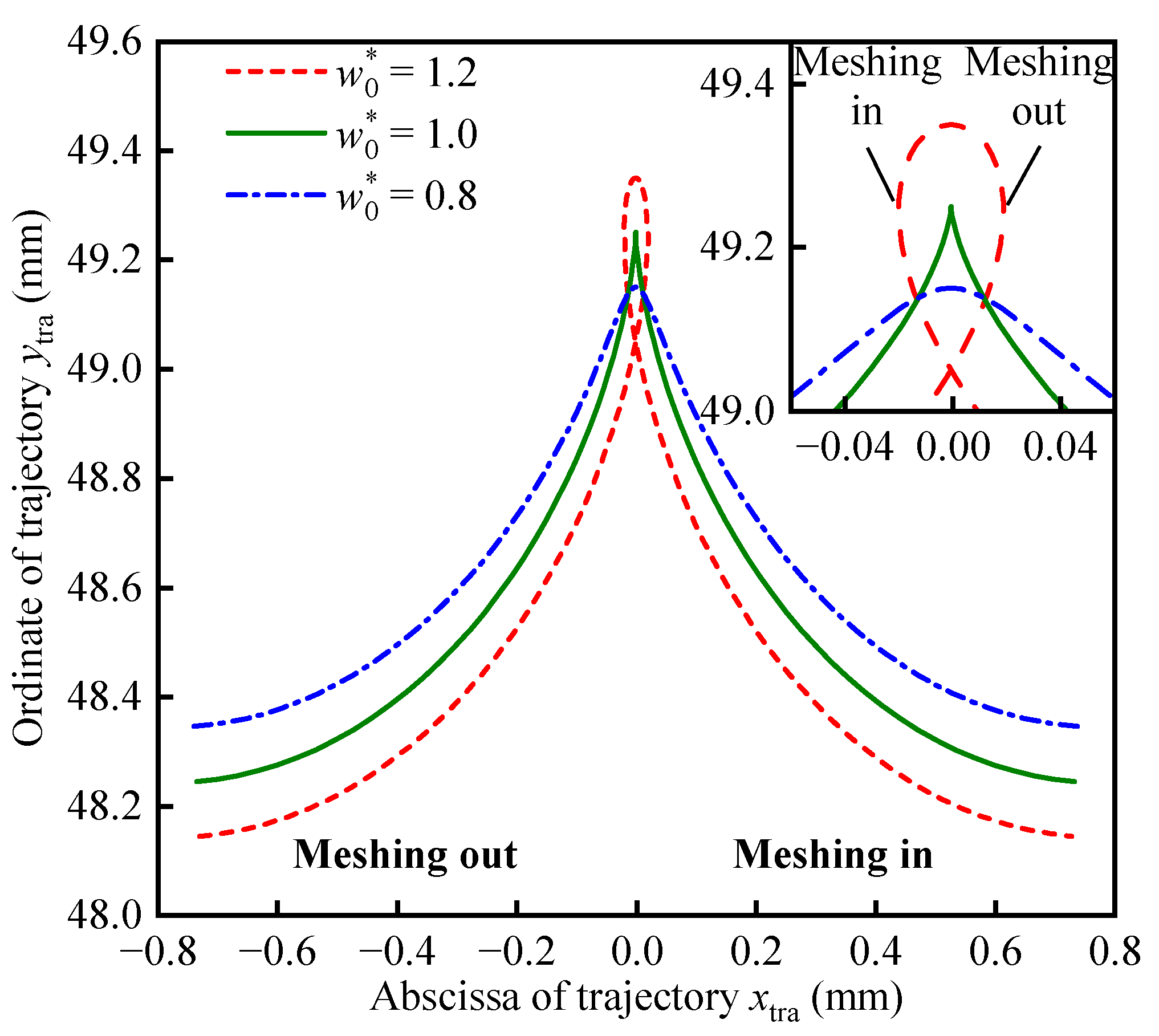
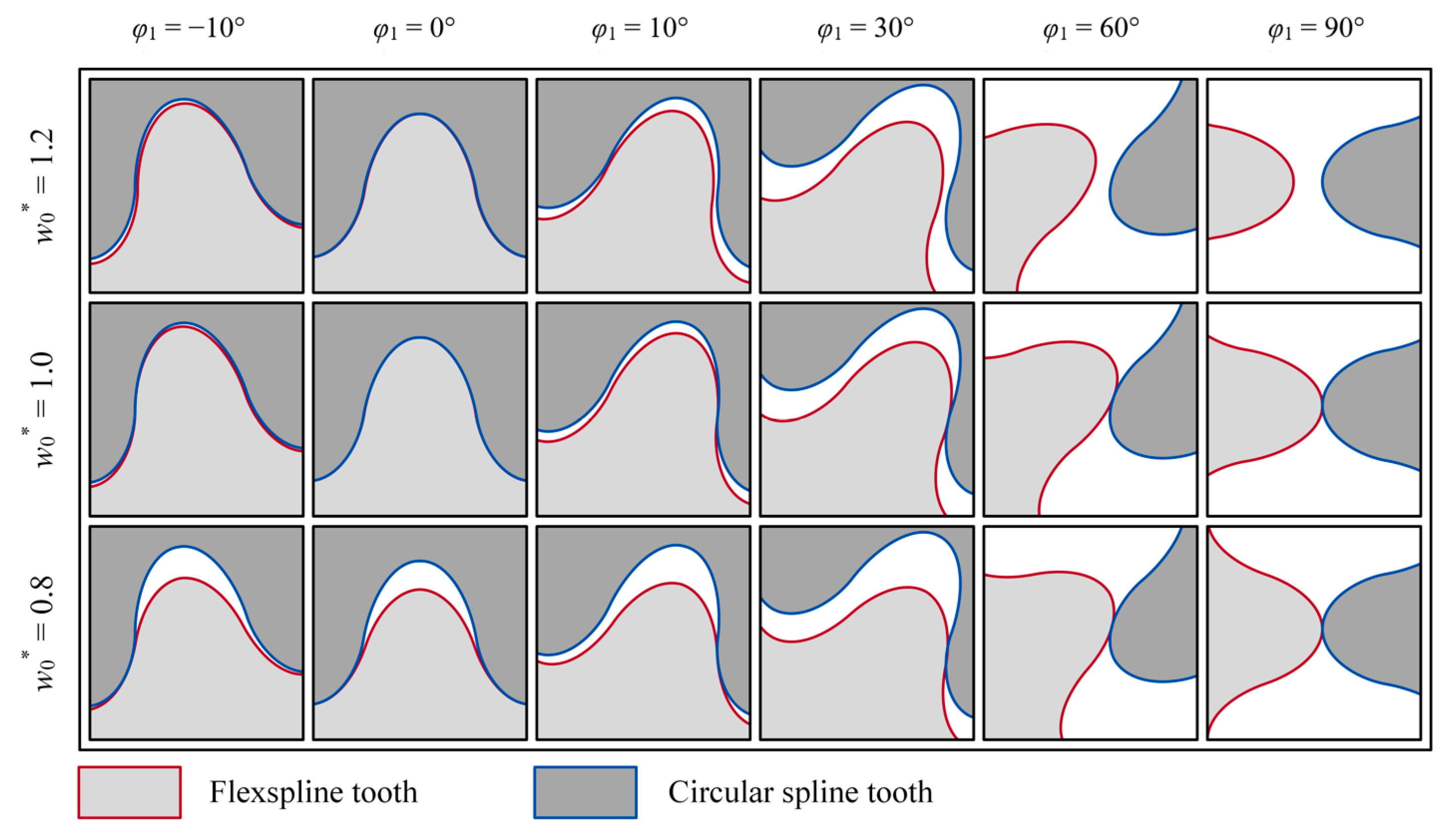
Therefore, the tooth trajectory exhibits cycloid characteristics. While the tooth trajectory can display different characteristics (see Figure 8 for details when w0* = 1.2 and w0* = 0.8), both prolate cycloids and curtate cycloids can effectively match these variations. However, the standard cycloid (Equation (9)), which aligns with the tooth trajectory when w0* = 1.0, is the most convenient for curve mapping calculations.
2.3. X-Halved Cycloid Tooth Trajectory
Let the radius of the rolling circle in Equation (9) be equal to the modulus of the HD, i.e.,
rg =
m. A cycloid with the
x-coordinate compressed by half is constructed as follows:
The geometry, slope, and curvature of the tooth trajectory and the cycloid expressed in Equation (10) are calculated and illustrated in
Figure 3.
Figure 3a illustrates the trajectory (
xtra,
ytra) of a complete meshing process of the FS’s tooth as
φ1 varies from 0 to π/2, alongside the cycloid (
xcyc,
ycyc), with its
x-coordinate halved as
t changes from 0 to π. Although the ordinate ranges of the two curves are not consistent, the geometric shape of the tooth trajectory aligns precisely with the cycloid in which the
x-coordinate is halved. Furthermore, as shown in
Figure 3b,c, the slope and curvature of the tooth trajectory and the cycloid are identical.
The results in
Figure 3 demonstrate that the tooth trajectory can be approximately expressed by a cycloid with its
x-coordinate halved. Since the tooth trajectory is a cycloid, the TP obtained using the halved mapping of the trajectory can also be represented by a cycloid. Therefore, the application of a CTP in HD is justified. Although these results are derived from the trajectory of a specific model under the influence of an elliptical WG, they also reflect, to a certain extent, the common characteristics of the tooth trajectory in harmonic drives.
3. Method of Cycloid Tooth Profile Design
Directly constructing the meshing TPs of the CS and FS based on the trajectory mapping curve represents a fundamentally sound approach. However, to address potential TP interference caused by the normal rotation of the FS, modifications to the TPs are essential [
21]. To meet the requirements of precise conjugation, the TP design can be refined using the envelope method. Additionally, the double-conjugate phenomenon in HD [
15,
18] can be leveraged to form viable conjugate TPs through practical design. The bidirectional conjugate design process [
16] further enhances this by maximizing the double-conjugation effect between meshing tooth pairs. In this section, the addendum profile of the CS is selected as the initial TP, and its CTP equation is formulated based on cycloid mapping. Subsequently, the complete TPs of the CS and FS are achieved through the bidirectional conjugate design process.
3.1. Construction of Initial Cycloid Tooth Profile
As demonstrated in
Section 2, the tooth trajectory can be approximated using the cycloid expressed in Equation (10). Consequently, the initial cycloid is constructed by halving the radius of the rolling circle in Equation (10) (i.e.,
rg =
m/2) as follows:
Point symmetry of Equation (11) about the point (0, 0) is as follows:
In the subsequent description, the cycloid expressed in Equation (11) is referred to as the D-cycloid, and the cycloid expressed in Equation (12) is referred to as the U-cycloid. According to the FS tooth coordinate system
S1 and the CS tooth coordinate system
S2 shown in
Figure 1, Equations (11) and (12) can be transformed to represent the TPs of the FS and CS, respectively.
Research on the double-conjugation phenomenon [
15,
18] has demonstrated that the conjugate result of a convex TP is the primary consideration in TP design. Therefore, the convex TP of either the FS’s tooth addendum or the CS’s tooth addendum can be selected as the initial TP. In this case, the addendum TP of the CS is chosen as the initial TP. According to the coordinate system
S2 in
Figure 1 and the D-cycloid equation expressed in Equation (11), the initial CTP {
xd2(
t),
yd2(
t)} of the CS’s tooth addendum has the following relationship:
here,
Ad2 is the scaling coefficients matrix of the D-cycloid, where axd2 is the x-scaling coefficient, ayd2 is the y-scaling coefficient, and ard2 is the scaling coefficient of the rolling circle radius; Bd2 is the coordinate translation matrix of the initial cycloid (Equation (11)) when expressing the addendum profile of CS in coordinate system S2; et2 is the width of the tooth space on the reference circle of CS, bd2 is the x-translation coefficient, and Ra2 is the addendum circle radius of CS. These coefficients allow for the adjustment of the initial cycloid from multiple perspectives, significantly enhancing the design flexibility of the cycloid.
3.2. Envelope of Initial Cycloid Tooth Profile
According to
Figure 1, the transformation matrix from coordinate system
S2 to
S1 is as follows:
Therefore, the addendum profile of CS shown in Equation (13) is transformed into the coordinate system
S1 as follows:
here, both
xd21 and
yd21 are functions with variables t and
φ1, i.e., they represent a cluster of curves distributed along
φ1. If an envelope curve exists for this curve cluster, the points on the envelope curve satisfy the envelope condition expressed in Equation (15).
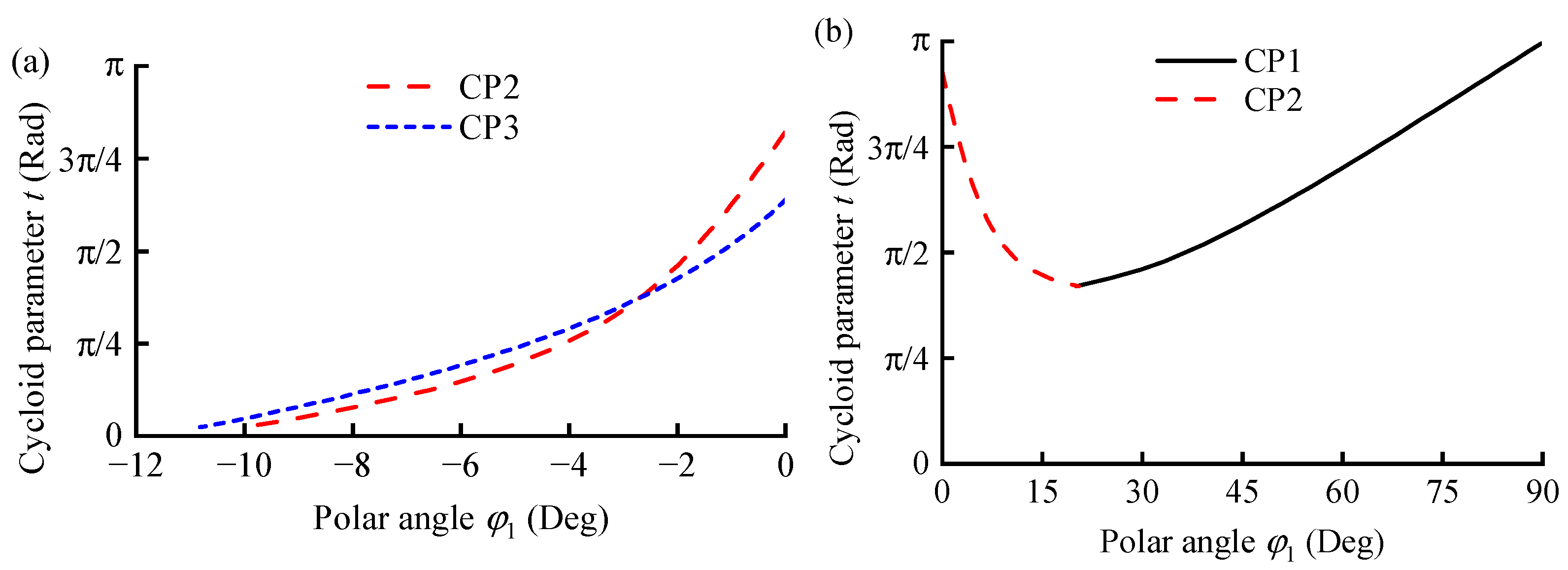
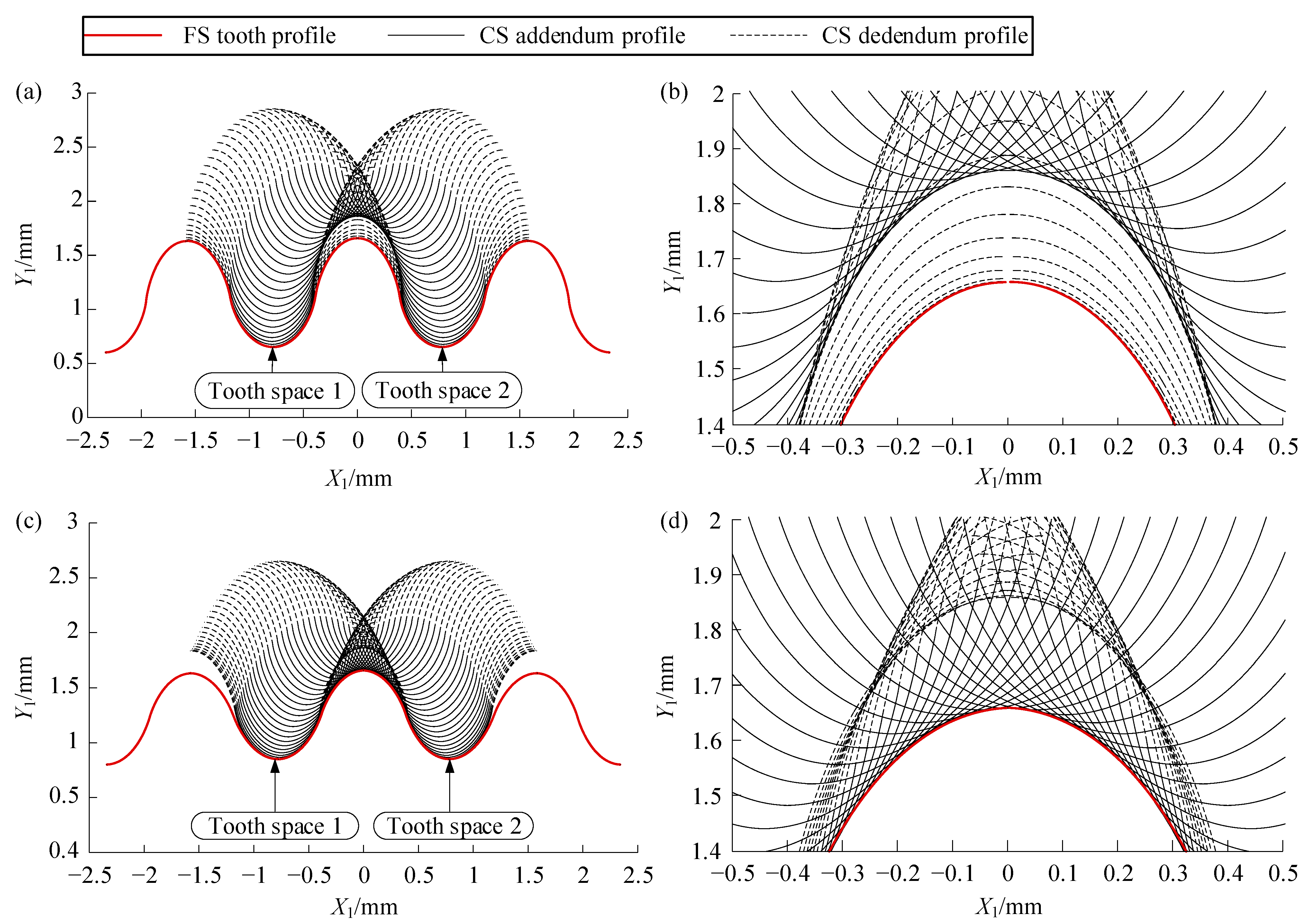
Parameter t of the TP, which satisfies the conjugate condition for any φ1, can be determined using Equation (15). By substituting t and φ1 into Equation (14), the discrete conjugate point of the CS’s addendum can be obtained.
3.3. Cycloid Tooth Profile Design of Flexspline
Preliminary studies on the composite cycloid [
24] indicate that the conjugate points of the CTP retain a cycloidal shape and should incorporate a specific TP angle. Trial calculations of the envelope reveal that the conjugate points forming the FS TP not only appear outside the reference circle but also partially distribute within it. Consequently, a CTP with a non-zero TP angle can be constructed, as illustrated in
Figure 4.
The TP angle at the joint point of the two cycloids can serve as a design variable, thereby further enhancing the design flexibility of the CTP. In
Figure 4, AB represents a U-cycloid, and CD represents a D-cycloid. The tangent angle of
AB at point
E is
α0, and the tangent angle of
CD at point
F is also
α0. By translating
AB, the CTP with TP angle
α0 can be obtained by smoothly connecting
AB and
CD at points
E and
F. The expression {
xd1(
t),
yd1(
t)} of FS’s dedendum CTP has the following relationship:
here,
The initial expression {
xu1(
t),
yu1(
t)} of the FS’s addendum CTP has the following relation:
here,
here,
axd1 and
axu1 are the
x-scaling coefficients;
ayd1 and
ayu1 are the
y-scaling coefficients;
ard1 and
aru1 are the scaling coefficients of the rolling circle radius;
st1 is the tooth thickness of FS on the reference circle (where
st1 =
et2), and
bd1 and
bu1 are the
x-translation coefficients.
Calculate the first-order derivatives of the U-cycloid and D-cycloid of the FS,
Let the tooth angle at the connection of the U-cycloid and D-cycloid of the FS be
α01. The slope at this position is −cot(
α01). Consequently, the tooth parameters at points
E and
F can be determined as follows:
The coordinates of points
E and
F can be determined by substituting
tE1 and
tF1 into Equations (17) and (16), respectively. By translating the U-cycloid to align point
E with point
F, the addendum CTP of the FS is expressed as follows:
here, the independent variable
t takes values in the range from
tE1 to π.
According to Equation (16), the dedendum profile of FS is expressed as follows:
here, the independent variable
t takes values in the range from
tF1 to π.
Among the discrete conjugate points of the CS’s addendum, the points located inside the FS’s reference circle are selected for least-squares fitting, using Equation (19) as the target curve, to determine the coefficient matrices Ad1 and Bd1. Subsequently, the points outside the reference circle are fitted using Equation (18) to determine the coefficient matrices Au1, Bu1, and tooth angle α01 of the addendum cycloid of FS. This completes the design of the FS’s CTP.
3.4. Cycloid Tooth Profile Design of Circular Spline
As the FS’s addendum profile design has been completed, its conjugate calculation can be performed to complete the dedendum profile design of CS, which can realize the double-conjugate meshing. This process of the reverse conjugate design of CS’s dedendum by the addendum of FS, which was previously designed by the presetting CS’s addendum, is called a bidirectional conjugate design [
16].
Among the discrete conjugate points of the FS’s addendum, the points located inside the CS’s reference circle should align with the initial CTP of the CS addendum, while the points outside the CS’s reference circle can be used to design its dedendum TP. According to
Figure 1, the transformation matrix from the coordinate system
S1 to
S2 is
T21−1. According to Equation (13), the CTP of the CS’s dedendum is expressed as follows:
here, the independent variable
t takes values ranging from
tF2 to π.
The expression of the CS dedendum CTP is as follows:
here, the independent variable
t takes values ranging from
tE2 to π.


