Abstract
The geometric parameters of the Null-Flux coil (NFC) are crucial to the load capacity and economic viability of electrodynamic suspension (EDS) systems. This study investigates the influence of NFC geometry on the electromagnetic force characteristics in EDS systems. Through the electromagnetic modeling of EDS mechanisms, an analytical model for EDS systems is established. Systematic experiments compare electromagnetic forces under varying NFC lengths and gaps, supported by a self-developed stationary EDS dynamic simulation platform. The results demonstrate that the average levitation force is positively correlated with the coil length, and it is larger when the coil length is close to its width. Meanwhile, the NFC length has a significant impact on the lift-to-drag ratio, while the NFC gap has a relatively smaller effect on it. This work provides a complete methodology integrating analytical modeling and experimental validation, offering practical guidelines for NFC design in maglev actuators. The findings advance EDS system optimization through quantifiable geometric criteria, particularly for transportation applications requiring precision electromagnetic force control.
1. Introduction
The electromagnetic levitation (EDS) system is a critical technology in the field of magnetic levitation, offering significant potential, particularly in the development of next-generation high-speed transportation systems. The origins of EDS can be traced back to 1966, when the concept was first proposed by Powell and Danby [1]. EDS systems can be categorized into two types based on track structure: Null-Flux Electromagnetic Suspension (Null-Flux EDS) and Plate Electromagnetic Suspension (Plate EDS) [2]. This paper focuses primarily on Null-Flux Electromagnetic Suspension. Since the 1960s, Japan has been a leading force in advancing EDS magnetic levitation technology. The nation’s first EDS test track was established in Miyazaki Prefecture in 1977, where the first unmanned test vehicle, the ML500, achieved a speed of 517 km/h. A full-scale test track was later built in Yamanashi Prefecture in 1996, and in 2015, the L0-900 series train developed by the Central Japan Railway Company set a new speed record of 603 km/h on this track, as shown in Figure 1 [3].
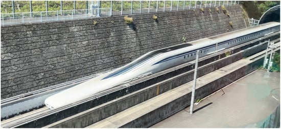
Figure 1.
The L0 series train operates at high speeds on the Yamanashi test line.
In the Null-Flux EDS system, the geometric parameters of the zero magnetic flux coil are pivotal to the system’s electromagnetic performance. These parameters directly affect the electromagnetic interaction between the track and the onboard magnetic field sources, which in turn determines the system’s maximum load capacity, stability, and overall economic feasibility.
Analytical methods are the primary theoretical approach for studying the operational behavior of EDS systems. Carbonari et al. [4] derived the electromagnetic force relationship between the superconducting coil and the ground coil using the energy method. He et al. [5] employed the dynamic circuit theory to analyze the EDS system, developing a comprehensive dynamic circuit model and investigating the dynamic motion characteristics of the train in longitudinal motion through analytical calculations. This approach has become one of the key methods for analyzing EDS systems. A crucial element of this model is the calculation of the mutual inductance between the superconducting coil and the track coil. For this purpose, He et al. [5] utilized a harmonic approximation method. Other approaches, such as empirical formulas, Neumann’s formula [6,7,8,9], the finite element method [10], and direct experimental measurements, can also be employed to compute the mutual inductance.
The finite element method (FEM) is commonly used to analyze EDS systems. In [11], an EDS model was constructed using the FEM, where the components were divided into fixed and moving parts, and overall displacement was applied to the moving components to avoid the deformed mesh method. Additionally, in [7,12], a cross-connected circuit of the upper and lower loops of the zero magnetic flux coil was created, simplifying the geometric model.
Furthermore, to optimize the electromagnetic suspension system, Ref. [13] applied the dynamic circuit theory to optimize the design of the superconducting coil’s dimensions, improving the levitation performance. In [14], the dimensions of the superconducting coil and zero magnetic flux coil were optimized, enhancing the levitation height stability. In [15], a design model for analyzing the EDS system was proposed, analyzing the effect of different ratios between the pole distances of the zero magnetic flux coil and superconducting coil on the levitation force, the guiding force, and their fluctuations.
Currently, apart from a few organizations that have full-scale EDS test lines for conducting research on EDS-related technologies, most researchers can only study and optimize EDS systems through theoretical analysis and simulation. This paper will use a stationary EDS test device to test various NFC geometry parameters and study their impact on the electromagnetic force characteristics of the EDS system.
2. Basic Principle of Null-Flux EDS
The basic principle of the Null-Flux EDS system is illustrated in Figure 2. NFCs are placed along the guideway, with each set consisting of two oppositely connected coils. The train’s bogie is equipped with magnet field sources, typically superconducting magnets or Halbach permanent magnet arrays.
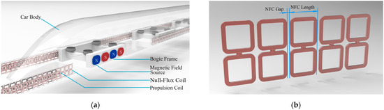
Figure 2.
(a) The basic structure of the Null-Flux EDS system; (b) the NFC structure and arrangement.
As the train moves, the moving magnetic field induces a current in the NFC due to the variation in the magnetic flux, leading to the generation of electromagnetic forces. When the MFS (magnetic field source) is aligned with the NFC, the induced electromotive forces (EMFs) in the upper and lower coils cancel each other out, resulting in no levitation force. However, a vertical displacement causes an imbalance in the EMFs, which in turn generates an induced current that produces a levitation force. The upper coil generates an attractive force, while the lower coil provides a repulsive force, collectively maintaining stable levitation.
More details on EDS can be found in [16,17].
3. Mathematics Modeling of EDS Systems
We establish the EDS mathematical analytical model based on the following assumptions:
NFCs are placed at equal intervals on the track, with identical geometric and electrical parameters. The magnetic field source generates a constant magnetic field, unaffected by external factors. The influence of any objects other than the NFCs and the magnetic field source on the magnetic field and electromagnetic forces is neglected.
The mathematical model is as follows:
where is the resistance of the NFC, is the self-inductance of the NFC, is the EMF in the th NFC, and is the induced current in the th NFC; where , is the total mutual inductance between a certain NFC and its adjacent -th NFC and is the mutual inductance between the coil and coil . represents the mutual inductance between the upper (or lower) coil of a given NFC and the upper (or lower) coil of the th adjacent NFC. is the self-inductance of the upper coil in the NFC and is the self-inductance of the NFC. The calculation method for the coil self-inductance can refer to [18].
The mutual inductance between NFCs can be calculated using the Neumann formula.
where and represent the two NFCs, and are the differential wire segments of the two NFCs, and is the relative distance between the differential elements of the wire segments in space. is the permeability of the free space.
According to Faraday’s law of electromagnetic induction, we have the following:
where is the induced EMF in the th NFC, is the magnetic flux through this NFC, and is the y-component of the magnetic flux density.
The electromagnetic force on the MFS can be calculated using Ampère’s force law. Directly calculating this force requires determining the magnetic field generated by multiple NFCs, which results in high computational complexity. Therefore, the electromagnetic forces acting on the NFCs are calculated instead by Newton’s third law, obtaining the electromagnetic force exerted on the MFS.
where is the magnetic force, is the current flow in the NFC, is a segment of the coil, is the magnetic torque, and is the position vector of the NFC segment. To accurately reflect the influence experienced by the permanent magnet, the origin of the displacement vector is set at the center of the permanent magnet.
Using the above formulas, we can calculate the electromagnetic force and electromagnetic torque of the single-sided EDS system under different operating conditions.
4. Stationary Simulation Platform for Null-Flux EDS
The stationary simulation method [19] for Null-Flux EDS systems allows for simulating the dynamic electromechanical characteristics of the system without the need for high-speed motion. The structure of the experimental setup is shown in Figure 3.
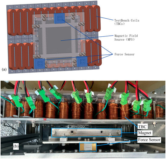
Figure 3.
(a) A schematic diagram of the experimental test device and (b) the actual structure.
This method replaces the traditional moving test platform with a fixed array of test bench coils (TBCs) that are powered by dynamically controlled currents. These TBCs replicate the electromagnetic forces and torques produced by the moving system, thus providing a real-time simulation of the system’s dynamics.
The key principle of the method is to simulate the interaction between the NFCs and the magnetic field source (MFS) using a fixed coil arrangement. The TBCs are designed to have the same vertical dimensions as the NFCs but narrower horizontal dimensions. This allows them to simulate the magnetic fields generated by the moving MFS by applying appropriate currents to the coils. The magnetic force and torque experienced by the MFS are then calculated based on these currents.
In addition, this method can also indirectly obtain the magnetic field characteristics using the TBC unit current electromagnetic force characteristics, without the need to measure the magnetic field, thus accurately reflecting the electromagnetic force characteristics of the NFC when it moves within the magnetic field.
In the experiment, we are able to define virtual NFCs with any length and gap, and use the test bench to reproduce the electromagnetic force and torque generated by the virtual NFCs with given parameters when passing through the magnetic field source of the test bench. To achieve this, we need to pre-calculate the electrical parameters of the virtual NFCs, including the resistance, self-inductance, and mutual inductance with other NFCs. These calculations will provide the necessary foundational data for further experiments and simulations, allowing us to accurately simulate the variations in the electromagnetic force and torque under different configurations.
5. Calculation and Experimental Results
First, we calculated the resistance, self-inductance, and mutual inductance between different NFCs under varying parameters. The NFC length was scanned in the range of 90 mm to 250 mm with a step size of 20 mm. Considering that smaller NFC lengths may result in larger parameter variations, an additional NFC length of 100 mm was included. The NFC gap was scanned in the range of 0 mm to 60 mm with a step size of 10 mm. However, since an NFC gap of 0 mm could introduce significant errors in the mutual inductance calculations, 5 mm was used instead as the minimum parameter. As the distance increases, the mutual inductance between the NFCs decreases sharply, and its influence on the system becomes negligible. Through calculations, we found that when the gap between two NFCs exceeds the length of one NFC, their mutual inductance approaches zero. Therefore, we only considered the mutual inductance between each NFC and the two adjacent NFC groups. The results are shown in Figure 4 and Figure 5.
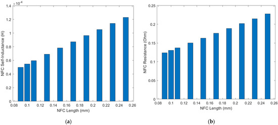
Figure 4.
(a) The self−inductance and (b) resistance of the NFC under different NFC lengths.
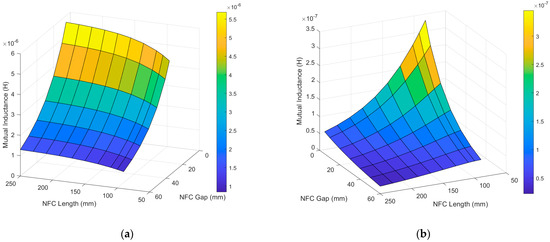
Figure 5.
(a) Mutual inductance between two adjacent NFCs; (b) mutual inductance between two NFCs separated by one NFC.
The self-inductance and resistance of the NFC are intrinsic parameters of the NFC itself and are independent of the distance between the NFCs. Both the self-inductance and resistance increase as the length of the NFC increases.
We also calculated the mutual inductance between the NFCs under different NFC lengths and gaps. Due to the positional relationship between the NFCs, the mutual inductance is negative. In the following discussion, the mutual inductance refers to the absolute value of the mutual inductance.
The results show that the mutual inductance between two adjacent NFCs decreases as the gap increases, while it increases slowly with the NFC length. For two NFCs separated by one NFC, the mutual inductance increases as the gap decreases but decreases as the NFC length increases. This may be due to the fact that, for adjacent NFCs, the gap remains relatively small, so the increase in the coil area leads to a larger increase in the magnetic flux passing through the coil compared to the decrease in the flux caused by the increased coil gap due to the lengthening of the NFC. However, for two NFCs separated by one NFC, the increase in the NFC length significantly increases the gap between the two NFCs, which dominates the effect, causing the mutual inductance to decrease as the coil length increases.
Based on the calculated NFC parameters, we conducted dynamic EDS simulation experiments using a stationary experimental setup. The experimental parameters are shown in Table 1.

Table 1.
Stationary test bench parameters.
We tested the effect of different NFC gaps on the levitation force when the NFC length is 130 mm. The results are shown in Figure 6.
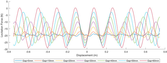
Figure 6.
Levitation force curves under different NFC gaps when NFC length is 130 mm.
As shown in Figure 6, the levitation force fluctuates in a sinusoidal-like manner, with the wavelength approximately equal to the NFC gap. Meanwhile, as the NFC gap increases, the average levitation force decreases, and the fluctuation of the levitation force becomes more intense. This indicates that the NFC gap has an impact on the variability of the levitation force.
Next, we tested the effect of the different NFC lengths on the levitation force when the NFC gap is 30 mm. The results are shown in Figure 7.
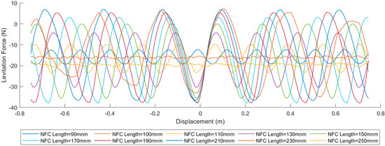
Figure 7.
Levitation force curves under different NFC lengths when the NFC gap is 40 mm.
As shown in Figure 7, when the NFC length increases, the fluctuation of the levitation force first decreases and then increases, while the average levitation force first increases and then decreases. Both of these turning points occur at an NFC length of 110 mm. Furthermore, for the NFC lengths greater than this value, the phase of the levitation force curve is opposite to that of the curve for the NFC lengths less than or equal to this value. This may be due to the levitation force characteristics of the front and rear NFCs. As the NFC length increases, the NFC gap also increases under the same NFC spacing, which leads to a change in the characteristics of the combined levitation force curve after the forces from the NFCs are superimposed.
Next, we tested the levitation force and the lift-to-drag ratio under NFC gaps ranging from 5 mm to 60 mm and NFC lengths ranging from 90 mm to 250 mm. The results are shown in Figure 8.
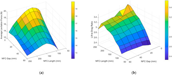
Figure 8.
(a) The average levitation force under the different NFC lengths and NFC gaps and (b) the lift-to-drag ratio.
As shown in Figure 8, under the same NFC gap, the levitation force first increases and then decreases as the NFC length increases. As the NFC gap increases, the turning point of the levitation force gradually shifts from around 150 mm to around 130 mm. Under the same NFC length, the levitation force decreases as the NFC gap increases. The point of the maximum average levitation force occurs at an NFC length of 130 mm and an NFC gap of 5 mm.
The variation of the lift-to-drag ratio is somewhat complex. Under the same NFC length, the lift-to-drag ratio slowly decreases as the NFC gap increases, although this characteristic is not significant when the NFC length is relatively small. Under the same NFC gap, as the NFC length increases, the lift-to-drag ratio first increases and then decreases. Furthermore, as the NFC gap increases, the NFC length corresponding to the turning point of the lift-to-drag ratio continuously decreases, and the corresponding lift-to-drag ratio also decreases. According to the laws of thermodynamics, the work done by the magnetic resistance when the train moves is almost entirely dissipated as Joule heat generated by the current inside the NFC. Meanwhile, due to the self-adaptability of the levitation height in the EDS system, the levitation force experienced by the train remains unchanged regardless of the track type, as long as the train’s mass is constant. Therefore, the lift-to-drag ratio of the train serves as an excellent indicator of energy loss during its operation and can be considered an important metric for assessing the operational efficiency of the train.
Based on the above experimental results, it can be concluded that reducing the NFC gap and simultaneously decreasing the NFC length is beneficial for improving the average levitation force, increasing the lift-to-drag ratio, and reducing the fluctuation of the levitation force. These metrics are crucial for the performance and stability of the train. However, both reducing the NFC gap and decreasing the NFC length led to an increase in the NFC volume per unit length of the track. Considering that NFCs are mainly made of copper wire to reduce resistance, this would significantly increase the amount of copper used and, in turn, raise the cost of the track construction. Worse still, the increase in the NFC volume per unit length due to reducing the NFC gap and length is not linear. We calculated the volume per unit length of the NFC for the different NFC gaps and lengths, as shown in Figure 9.
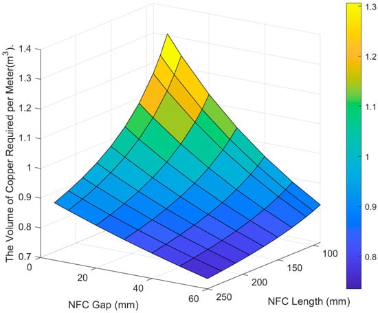
Figure 9.
The volume of copper required per meter under the different NFC gaps and NFC lengths. This figure only calculates the impact of the NFC required for a single-sided track.
As the NFC gap decreases, the NFC volume increases exponentially. Reducing these parameters within a smaller range leads to a rapid increase in the NFC volume per unit length. This is because each NFC consists of both vertical and horizontal wire segments, and shortening the NFC length only reduces the volume contribution of the horizontal wire segments, while the contribution from the vertical wire segments remains unchanged. Considering that in practical applications, there are also cross-connected wires on both sides of the NFC along the track, these wires will not decrease in size as the NFC length reduces. Therefore, the cost increase caused by shortening the NFC length will be even more significant.
6. Conclusions
This study systematically examined the effects of various parameters on the performance of NFCs, particularly focusing on the resistance, self-inductance, and mutual inductance and their influence on levitation forces in EDS systems. Our findings demonstrate that the mutual inductance between NFCs is highly sensitive to the distance between them, becoming negligible when the gap exceeds the NFC length. Additionally, we observed that the self-inductance and resistance increase with NFC length, but these parameters remain largely unaffected by the spacing between the NFCs.
From a practical standpoint, the gap and length of the NFCs significantly impact the levitation forces. As the gap between the NFCs increases, the levitation force fluctuates more intensely, and its average value decreases. This fluctuation is closely related to the NFC gap, which influences the stability of the levitation in EDS systems. Interestingly, an increasing NFC length results in a more complex relationship with the levitation force, with both the fluctuations and average force first increasing and then decreasing after reaching a critical length. This suggests that there is an optimal NFC length for balancing the force stability and efficiency.
Furthermore, the analysis of the lift-to-drag ratio revealed that reducing the NFC gap and length can improve the levitation performance and stability. However, these benefits come with a trade-off: a reduction in the gap and length significantly increases the volume of the NFC material per unit length of track, particularly due to the nonlinear relationship between the NFC volume and the gap/length changes. This increase in the NFC material volume is accompanied by a rise in material costs, especially given the substantial use of copper to minimize resistance.
Ultimately, while minimizing the NFC gap and length improves the system performance, these changes must be carefully balanced with the associated cost and material considerations. The results suggest that a trade-off approach, optimizing the NFC design for both performance and cost efficiency, is essential for future EDS applications.
Author Contributions
Conceptualization, J.L. and J.Z.; methodology, J.L. and J.Z.; software, J.L.; validation, J.L.; writing—original draft preparation, J.L.; writing—review and editing, J.L., J.Z. and Y.Y.; visualization, J.L.; supervision, J.Z.; funding acquisition, J.Z. All authors have read and agreed to the published version of the manuscript.
Funding
This research was funded by the Sichuan Science and Technology Program under Grant 2024JDHJ0002.
Data Availability Statement
Data are contained within the article.
Conflicts of Interest
The authors declare no conflicts of interest.
Abbreviations
The following abbreviations are used in this manuscript:
| EDS | Electrodynamic Suspension |
| NFC | Null-Flux Coil |
| TBC | Test Bench Coil |
| MFS | Magnetic Field Source |
| EMF | Electromotive Force |
References
- Powell, J.R. High-speed transport by magnetically suspended trains. ASME Pap. 1966, 66, 1. [Google Scholar]
- Abdelrahman, A.S.; Sayeed, J.; Youssef, M.Z. Hyperloop transportation system: Analysis, design, control, and implementation. IEEE Trans. Ind. Electron. 2017, 65, 7427–7436. [Google Scholar] [CrossRef]
- He, J.L.; Rote, D.M.; Coffey, H.T. Study of Japanese Electrodynamic-Suspension Maglev Systems. 1994. Available online: https://www.osti.gov/servlets/purl/10150166.Â%C2%A0 (accessed on 8 April 2025).
- Carbonari, N.; Martinelli, G.A.; Morini, A. Calculation of levitation, drag and lateral forces in EDS-MAGLEV transport systems. Arch. Elektrotechnik 1988, 71, 139–148. [Google Scholar] [CrossRef]
- He, J.L.; Rote, D.M.; Coffey, H.T. Electrodynamic Forces of the Cross-Connected Figure-Eight Null-Flux Coil Suspension System; No. ANL/ES/CP-79716, CONF-930550-2; Argonne National Lab.: Lemont, IL, USA, 1993. [Google Scholar]
- Cai, Y.; Ma, G.; Wang, Y.; Gong, T.; Liu, K.; Yao, C.; Yang, W.; Zeng, J. Semi-analytical calculation of superconducting electrodynamic suspension train using figure-eight-shaped ground coil. IEEE Trans. Appl. Supercond. 2020, 30, 3602509. [Google Scholar] [CrossRef]
- Huang, H.; Deng, Z.; Li, H.; Zhu, H.; Shi, H.; Zheng, J. Numerical simulation of dynamic electromagnetic characteristics of superconducting electrodynamic suspension (EDS) train. IEEE Trans. Appl. Supercond. 2021, 31, 3601105. [Google Scholar] [CrossRef]
- Zhu, H.; Huang, H.; Zheng, J.; Shi, H.; Xiang, Y.; Li, K. A numerical calculation model of multi-magnet-array and 8-shaped null-flux coil for permanent magnet EDS vehicle system. IEEE Trans. Magn. 2022, 58, 8300311. [Google Scholar] [CrossRef]
- Su, Z.; Luo, J.; Ma, G.; Liu, K.; Cui, L.; Wang, Y. Fast and precise calculation of mutual inductance for electrodynamic suspension: Methodology and validation. IEEE Trans. Ind. Electron. 2021, 69, 6046–6057. [Google Scholar] [CrossRef]
- Huang, H.; Luo, J.; Ma, G.; Liu, K.; Cui, L.; Wang, Y. Advancements in dynamic characteristics analysis of superconducting electrodynamic suspension systems: Modeling, experiment, and optimization. Superconductivity 2024, 11, 100114. [Google Scholar] [CrossRef]
- Chen, D.; Li, X.; Huang, X.; Sheng, J.; Wu, W.; Hong, Z.; Jin, Z.; Ma, H.; Zhao, T. An FEM model for evaluation of force performance of high-temperature superconducting null-flux electrodynamic maglev system. IEEE Trans. Appl. Supercond. 2021, 31, 3603806. [Google Scholar] [CrossRef]
- Gong, T.; Ma, G.; Wang, R.; Li, S.; Yao, C.; Xiao, L. 3-D FEM modeling of the superconducting EDS train with cross-connected figure-eight-shaped suspension coils. IEEE Trans. Appl. Supercond. 2021, 31, 3600213. [Google Scholar] [CrossRef]
- Gong, T.; Ma, G.; Li, J.; Zhao, Z.; Wang, R. Design optimization of high temperature superconducting magnets and null-flux coils for electrodynamic suspension train. IEEE Trans. Energy Convers. 2022, 37, 526–536. [Google Scholar] [CrossRef]
- Gong, X.; Lu, Q.; Li, Y. Multi-objective optimization for the levitation system of the electrodynamic suspension train with HTS magnets. In Proceedings of the 13th International Symposium on Linear Drives for Industry Applications (LDIA), Wuhan, China, 1–3 July 2021. [Google Scholar]
- Lim, J.; Lee, C.Y.; Lee, J.H.; You, W.; Lee, K.-S.; Choi, S. Design model of null-flux coil electrodynamic suspension for the hyperloop. Energies 2020, 13, 5075. [Google Scholar] [CrossRef]
- Li, H.; Zheng, J.; Huang, H.; Fu, S. A partition-computing mechatronics dynamics modeling for superconducting electrodynamic suspension and the analysis on the discrete-track irregularity. IEEE Trans. Transp. Electrif. 2025, 11, 1901–1914. [Google Scholar] [CrossRef]
- Li, H.; Zhu, H.; Huang, H.; Li, H.; Deng, Z.; Zheng, J. A new suppression strategy of pitching vibration based on the magnetic-electric-mechanical coupling dynamic model for superconducting EDS transport system. Mech. Syst. Signal Process. 2023, 188, 110039. [Google Scholar] [CrossRef]
- Grover, F.W. Inductance Calculations: Working Formulas and Tables; Dover: New York, NY, USA, 1962. [Google Scholar]
- Liu, J.; Zheng, J.; Liu, R.; Luo, Y.; Yuan, Y.; Yan, W. A stationary simulation method for dynamic electromechanical characteristic in null-flux electrodynamic suspension systems. IEEE Trans. Ind. Electron. 2025; submitted. [Google Scholar]
Disclaimer/Publisher’s Note: The statements, opinions and data contained in all publications are solely those of the individual author(s) and contributor(s) and not of MDPI and/or the editor(s). MDPI and/or the editor(s) disclaim responsibility for any injury to people or property resulting from any ideas, methods, instructions or products referred to in the content. |
© 2025 by the authors. Licensee MDPI, Basel, Switzerland. This article is an open access article distributed under the terms and conditions of the Creative Commons Attribution (CC BY) license (https://creativecommons.org/licenses/by/4.0/).