Article

Modeling and Analysis of a Cutting Robot for the “Excavation–Backfill–Retention” Integrated Mining and Excavation Equipment

1
School of Mechanical Engineering, Xi’an University of Science and Technology, Xi’an 710054, China
2
Shaanxi Provincial Key Laboratory of Intelligent Testing and Control of Mine Mechanical and Electrical Equipment, Xi’an University of Science and Technology, Xi’an 710054, China
*
Author to whom correspondence should be addressed.
Actuators 2025, 14(4), 175; https://doi.org/10.3390/act14040175
Submission received: 18 February 2025 / Revised: 29 March 2025 / Accepted: 2 April 2025 / Published: 3 April 2025
(This article belongs to the Section Actuators for Robotics)

Abstract

:
To meet the mining requirements of the ’excavation–backfill–retention’ tunneling method for inter-panel coal pillars, this paper proposes an integrated ‘excavation–backfill–retention’ equipment system centered on a cutting robot. An interactive design method was employed to analyze the interaction between mining conditions and the cutting robot, constructing a ’requirements–functions–structure’ model. The robot integrates a horizontal drum cutting mechanism with a slider shoe walking mechanism, offering enhanced adaptability to various mining conditions. A parameter model was constructed to explore the relationship between the cutting arm length and the robot’s structural parameters under varying mining heights. Using a hierarchical solution method that combines local search and multi−objective genetic algorithms, the robot’s fundamental parameters were determined, enabling the development of a detailed 3D model. A kinematic model based on the modified D–H method was developed to analyze the cutting arm’s swing angle, cylinder extension, propulsion velocity, and cutting velocity in practical mining scenarios. The working range of the height adjustment and feed cylinders at different mining heights was determined through simulation. A dynamics model of the cutting drum was developed, and a coupled simulation using the discrete element method (DEM) was conducted to analyze the relationship between coal/rock hardness, drum load, and cutting depth. The simulation results indicate that as the cutting depth raises the number of cutting teeth in contact with surrounding rock, the cutting depth grows, resulting in a larger reaction force from the coal seam and greater fluctuations in drum load torque. Once the maximum cutting depth is reached, load torque stabilizes within a specific range. Considering cutting efficiency, the robot achieves a maximum cutting velocity of 1 m/min with a cutting depth of 250 mm for rock strength greater than f3. For rock strength f3, the maximum cutting velocity is 1 m/min with a 400 mm depth, and for f2, it is 2 m/min with a 400 mm depth. These findings provide a theoretical foundation for the development of adaptive cutting strategies in mining operations, contributing to improved performance and efficiency in complex mining conditions.

1. Introduction

Under the context of the “dual carbon” goals and current technological conditions [1], academician Shuangming Wang proposed the “excavation–backfill–retention” tunneling method for the mining of inter-panel coal pillars with a width of 15 m to 40 m and a height of 2.5 m to 4 m [2]. The basic implementation process of the “excavation–backfill–retention” method is as follows: Roadways are driven along the two sides of the originally planned inter-panel coal pillar from the transport roadway and return airway. Mechanized large-section tunneling and filling equipment are then deployed at the cut eye of the inter-panel coal pillar to achieve continuous forward excavation, backward filling, and reserved roadways on both sides. Compared with the traditional longwall mining method [3], this method displaces the original inter-panel coal pillar with a filling body, reducing resource waste caused by coal pillar retention. Simultaneously, it significantly improves the utilization efficiency of gangue through the construction of filling bodies, making it highly significant for green coal mining. Furthermore, large-section rectangular roadway excavation facilitates the arrangement of mechanized large-section tunneling and filling equipment and provides favorable conditions for the coordinated operation of tunneling and filling equipment. However, no existing mining equipment can meet the requirements for large-section rectangular roadway excavation, creating an urgent need to develop a cutting robot capable of fulfilling the requirements of this method. This cutting robot is a critical element for the successful implementation of the “excavation–backfill–retention” method, and its development will provide essential technical support for green coal mining.
At this stage of research, coal mining equipment currently in use can be broadly classified into two functional categories: excavation equipment and coal mining equipment. The characteristics of existing equipment are systematically summarized and their shortcomings explicitly highlighted in Table 1. Excavation equipment, defined as machinery used for roadway development, can be divided into four primary categories. The first category is the roadheader-based method [4], which is used to excavate rectangular and curved roadway cross-sections, with an excavation width ranging from 2 to 8 m [5]. The second category is the continuous miner-based method [6], which produces rectangular roadways. The HM series of continuous miners manufactured by JOY have a maximum mining width of 4.1–4.6 m and are among the largest continuous miners currently in operation [7]. The third category is the integrated bolting and mining machine method [8], where roadways are also rectangular. As of February 2023, the maximum height and width of roadways cut in China using this method are 5.5 m and 7.5 m, respectively. The fourth category is the shield intelligent tunneling system [9], which produces rectangular roadways with a maximum cutting height of 4.3 m and a width of 6.5 m [10]. Shortwall working faces, typically tens of meters to over 100 m in width, are well suited to meet the requirements of inter-panel coal pillar mining [11]. However, the use of shortwall miners or coal ploughs for such operations presents certain challenges in roadway formation and mining techniques [12].
In summary, to address the challenges of safe and efficient inter-panel coal pillar mining, a support mode for excavation and mining equipment, along with a novel cutting process centered on a long horizontal cutting robot, is proposed. An interactive mapping model of “requirements–functions–structure” for the cutting robot will be established to analyze the correspondence between the functional units of the robot and the mining requirements, thereby determining the robot’s composition and working principles. A cutting robot parameter analysis model will be developed to address the challenge of parameterizing the cutting robot for the target operating conditions. A kinematic model of the cutting mechanism will be created to determine the optimal parameters of the drive cylinder for varying mining heights, ensuring efficient operation. Additionally, a dynamic model of the cutting robot will be established to analyze and optimize the cutting dynamic parameters of the cutting robot for cutting different surrounding rocks under constant power.

2. Demand Analysis and Working Principle of the Cutting Robot

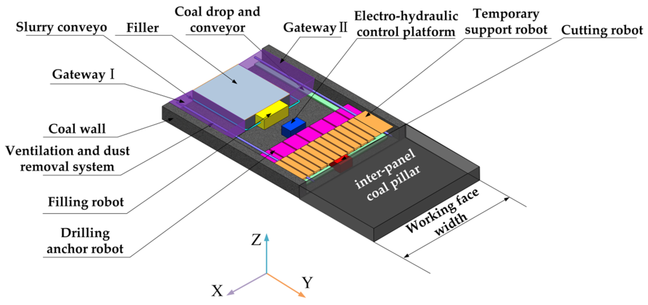
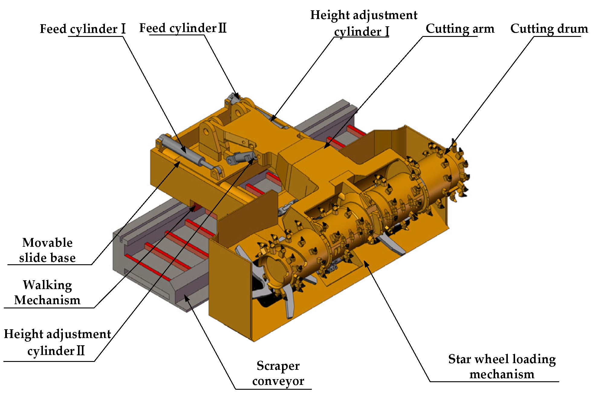
2.1. The System Design for the “Excavation–Backfill–Retention” Integrated Mining and Excavation Equipment

The system design for the “excavation–backfill–retention” integrated mining and excavation equipment developed by the research team is shown in Figure 1. The X-axis in the figure represents the working face width direction, the Y-axis represents the longitudinal roadway advancement direction, and the Z-axis represents the vertical direction of the roadway height.
The cutting robot is positioned at the front end of the entire machine and is responsible for cutting the roadway cross-section to create mining space. The temporary support robot is positioned behind the cutting robot and ensures a safe operational environment for both the cutting robot and the conveyor system. The drilling anchor robot performs roadway support operations using a drilling rig and associated auxiliary equipment. The filling robot is positioned at the end of the system and is responsible for injecting slurry from the conveyor into molds to form a stable support structure, rapidly forming a supporting filling body and constructing two gateways to facilitate further operations.

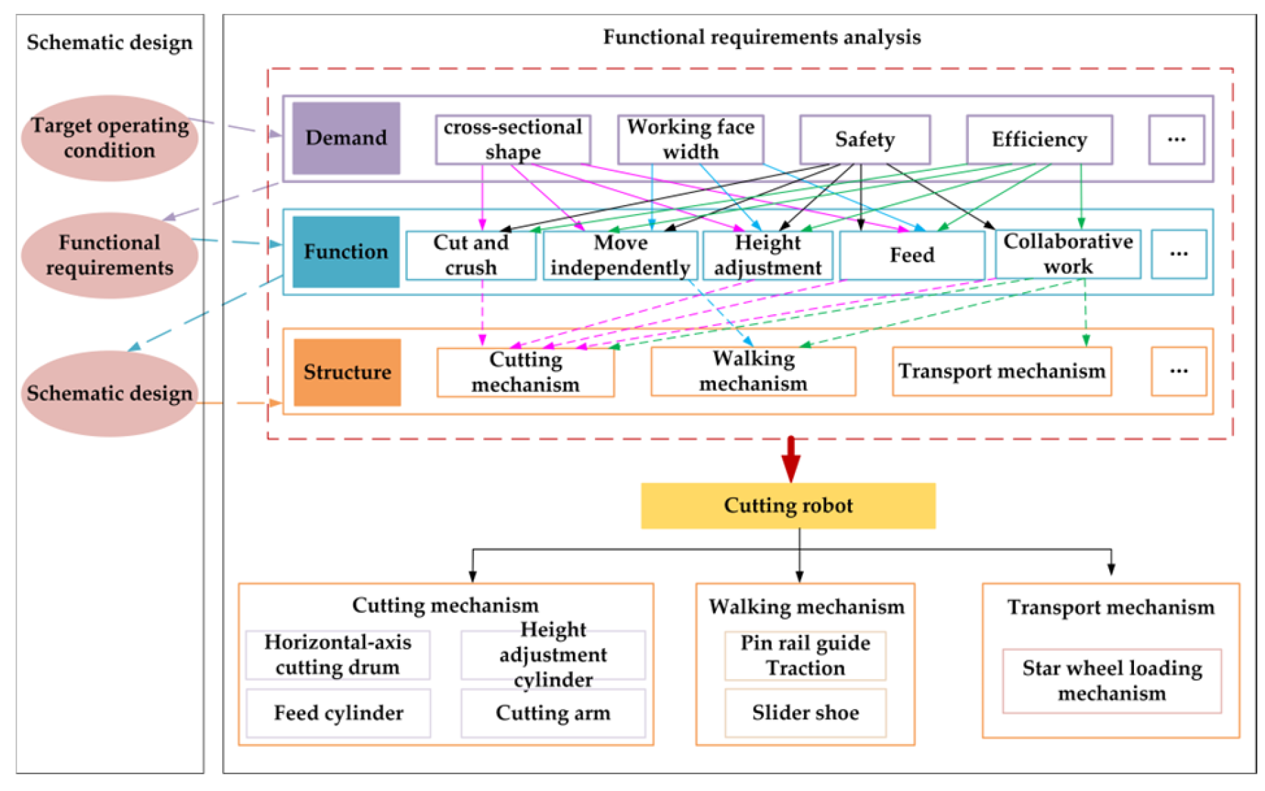
2.2. Demand Analysis for Cutting Robots

To meet the mining requirements for 15 m-to-40 m inter-panel coal pillars, the functional composition of existing mining equipment was summarized, as shown in the Table 2. Using the interactive design method described in [13,14], an interactive mapping model of the cutting robot’s “requirements–functions–structure” was established, as shown in Figure 2. The relationships among the demand domain, function domain, and structure domain of the cutting robot were analyzed, and the structures required to achieve the necessary functional units were combined. By applying the methods in [15,16], it was determined that the long horizontal-axis cutting mechanism, compared with other cutting mechanisms, avoids producing large areas of residual corner coal during the cutting process, thereby better meeting the requirements of the “excavation–backfill–retention” tunneling method for cutting precision and formation quality. While the crawler-based walking mechanism provides better mobility and travel capabilities compared to the slider shoe walking mechanism, it requires repeated entry and exit from the mining face during operation, which can result in delays in support installation. In contrast, the slider shoe walking mechanism ensures better continuity during mining operations and enables continuous extraction of inter-panel coal pillars through segmented cutting. Push–pull and wheel-based mechanisms were found to have poor adaptability under large cross-sectional conditions. For transportation, the built-in loading mechanism of the robot, combined with scraper conveyors and other transportation devices, provides faster material handling speeds. In contrast, shuttle car-based transportation requires mining equipment to stop during the transportation process, and when multiple devices operate simultaneously, it increases mining costs and process complexity, which is unfavorable for the efficient mining of inter-panel coal pillars. For support systems, the stepping temporary support system combined with a bolting and drilling rig can enable rapid roadway support. However, when the working face length is between 15 m and 40 m, the required number of equipment increases significantly, resulting in poor economic feasibility. Hydraulic supports, commonly used in underground coal mining, can work in conjunction with the bolting and drilling robot developed by the research team to complete roadway support tasks. The method of advancing the working face through hydraulic supports by pushing and shifting has been widely applied in underground operations, demonstrating good synergy and economic efficiency. Therefore, this study constructs the principle model of the cutting robot based on the long horizontal-axis cutting mechanism, the slider shoe walking mechanism, the transportation method combining the built-in loading mechanism with scraper conveyors, and the hydraulic support advancement system.

2.3. Cutting Robot Working Principle

The cutting robot consists of a horizontal-axis cutting drum, a cutting arm, a movable sliding seat, a star-wheel loading mechanism, as well as symmetrically arranged height-adjusting cylinders, feed cylinders, walking motors, guide shoes, and smooth shoes. The principle model of the cutting robot is shown in Figure 3. Compared with existing coal mining equipment [17], the cutting robot integrates the traveling mechanism of the shearer, the cutting mechanism of the long horizontal-axis cutting drum, and the star-wheel shovel-plate transportation mechanism combined with a scraper conveyor. This integration not only meets the requirements for inter-panel coal pillar mining and roadway formation between 15 m and 40 m but also avoids the cost increase and safety risks associated with multiple devices operating simultaneously. The design of the cutting robot should be based on existing horizontal-axis cutting equipment used in coal mines, prioritizing the selection of general components that have already been applied underground and proven to have a certain degree of reliability and safety. This approach ensures safety, reliability, and maintainability while reducing research and development costs.
The cutting robot adopts the mining method of “transverse cutting and segmented mining” to enhance mining efficiency and precision. Driven by the combined action of the height adjustment cylinder and feed cylinder, the cutting robot performs actions such as engaging the cut, retracting the cut, rising, and falling, to achieve the planned formation cut of the current section with precision. The transverse walking mechanism regulates the spacing between mining sections by driving the toothed wheel through the walking motor, which engages with the toothed rail of the scraper conveyor to enable precise positioning.
The loading device is positioned at the front end of the cutting robot and works in coordination with the cutting mechanism and scraper conveyor to ensure efficient removal and transportation of fallen coal during the mining process.

3. Design of Structural Parameters of Cutting Robot

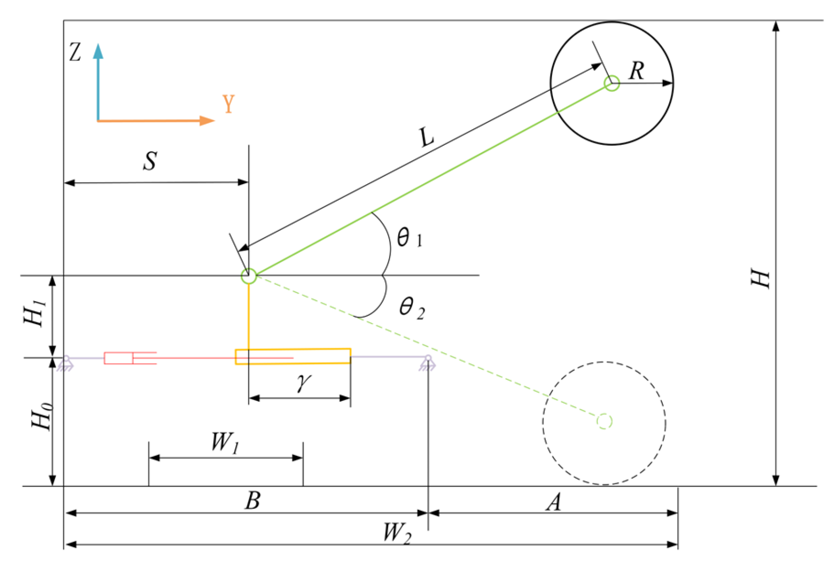
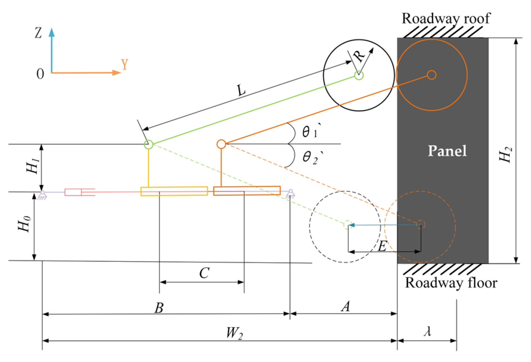
3.1. Modeling the Structural Parameters of the Cutting Robot

The development of a parameter analysis model for the cutting robot was based on the principle model of the cutting robot (see Figure 4) to analyze the relationships between structural and operational parameters. A is defined as the length of the cutting robot’s star-wheel loading mechanism along the direction of excavation. B is the length of the robot base. C is the maximum feed stroke of the feed cylinder. R is the radius of the cutting drum. E is the theoretical cutting depth for rectangular cutting. S is the distance from the cutting arm’s rotation center on the movable slide base to the rear of the robot. H represents the mining height of the cutting robot. H0 is the height of the robot body, determined by taking into account the mining height and the space required for installing the travel motor. H1 is the vertical distance from the center of the movable slide base to the body of the cutting arm. H2 represents the height of the coal seam, which determines the cutting height requirements. L is the distance between the center of rotation of the cutting arm on the sliding table and the axis of the cutting drum. W1 is the width of the transport trough of the scraper conveyor. W2 is the maximum length of the robot in the direction of excavation. θ1 and θ2 represent the rotational angles of the cutting arm driven by the height adjustment cylinder, where θ1 > θ2. γ represents the distance from the center of the axis of rotation of the cutting arm, driven by the height adjustment cylinder, on the slide to one end of the slide, accounting for the rotational displacement of the cutting arm. λ represents the maximum cutting interval for inter-panel coal pillar mining. In this study, λ is set to 800 mm, with λ < E. k1 and k2 are safety factors used to ensure operational safety. The mathematical relationship between these parameters is described in Equation (1), which serves as the basis for the parameter analysis model. Figure 5 illustrates the analytical model, which shows the relationships between the structural parameters of the cutting robot and the surrounding rock characteristics.
Based on Equation (1), assuming that H0, H1, and γ are constant values, 300 ≤ R ≤ 600, and 1000 ≤ A ≤ 2000, Figure 6 illustrates the variation in L as R and A change under different mining heights. As the mining height H increases, the range of feasible domains for L that meet the mining requirements expands incrementally. Under the same mining height conditions, the value of L is positively correlated with the parameters A and R, and grows proportionally with increases in A and R. When the mining height H = 5000 mm, due to the small fixed values set for H0, H1, and γ, the range of feasible domains for L that satisfy the requirements cannot be solved. Therefore, in the process of determining the structural parameters of the cutting robot, it is critical to account for the impact of the H0, H1, and γ values on the value of L based on the change in mining height H, to ensure that the cutting robot meets operational requirements. As H increases, the values of H0, H1, and γ must be appropriately adjusted according to specific working conditions to determine the feasible domain range of L that meets the requirements and to optimize the relevant parameters.
H = 2 R + L s i n θ 1 + s i n θ 2 L max = γ + A + λ + R c o s θ 1 m a x θ 1 = a r c s i n H H 0 H 1 R L θ 2 = a r c s i n H 0 + H 1 R L B = W 2 A = k 1 W 1 W 2 = k 2 L + S + R = B + A E = C L 1 c o s θ 1

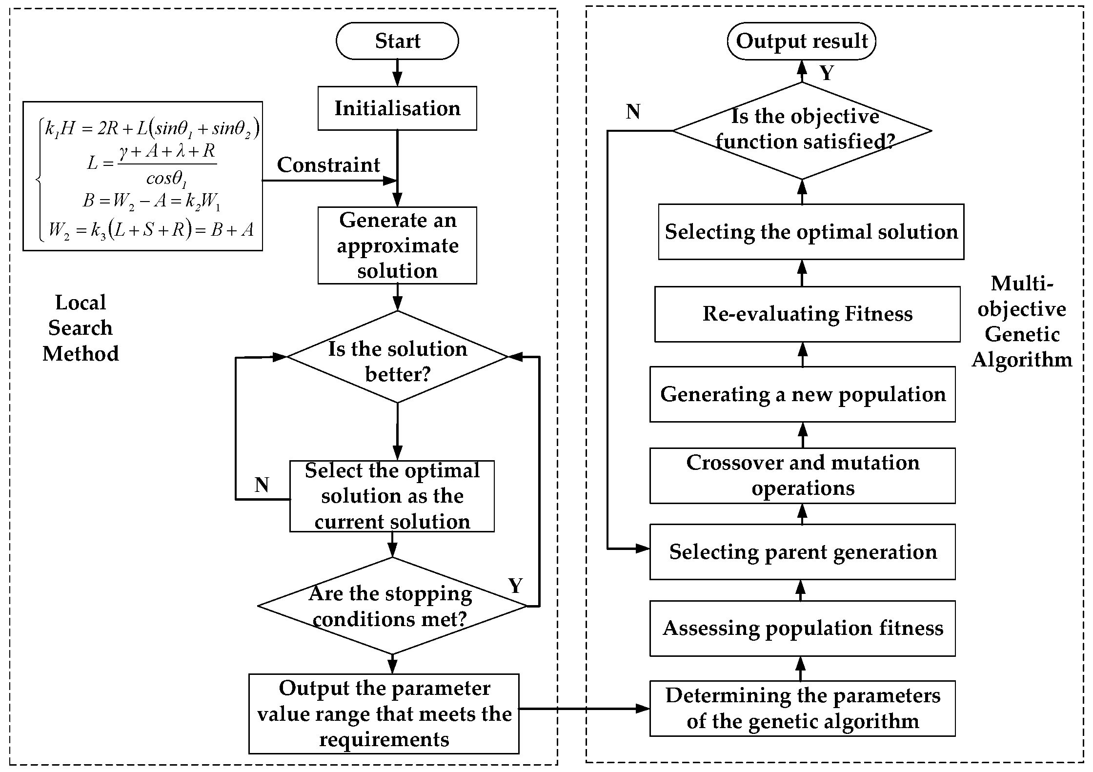
3.2. Solving for the Structural Parameters of the Cutting Robot

A layered parameter-solving method for the cutting mechanism is applied to address the optimization of cutting structure parameters under target operating conditions, as shown in Figure 7. Subject to the constraint of Equation (1), the local search method is employed to identify feasible ranges for each design parameter that satisfies the demand for maximum mining height, with reference to the parameters of existing mining and excavation equipment. The value ranges of L, S, A, H0, H1, θ1, θ2, γ, and R are refined by traversing all possible values within their initial ranges. These ranges of local optima are used as the initial parameter ranges for the multi−objective genetic algorithm to provide a foundational search space for optimization. Using the multi−objective genetic algorithm, all parameters are optimized under the constraints of the target mining roadway parameters to achieve a relatively optimal combination of parameters that satisfies the maximum mining height and the target roadway cross-section.
To address the parameter optimization problem of the cutting structure under the target working conditions, a layered solution method combining local search [18] and the multi−objective genetic algorithm (MOGA) [19] was adopted, as shown in Figure 7. Based on Equation (1) and empirical parameters from existing mining equipment, the initial value ranges of the design variables (L, S, A, H0, H1, θ1, θ2, γ, R) were estimated under the maximum mining height requirements. Neighborhood Search was employed as the local search method, with step sizes adjusted for different parameters. A greedy strategy was used to iteratively narrow the parameter range. If the objective function showed no significant improvement over several consecutive iterations and remained within a reasonable range, the search was considered converged, yielding a “locally optimal value range”. This range was then used as the boundary for the initial population in the multi−objective genetic algorithm.
The NSGA-II (Non-dominated Sorting Genetic Algorithm II) was subsequently applied to perform global optimization of all parameters. During this process, a multi−objective function was constructed to balance compactness and operational efficiency, aiming to minimize equipment dimensions and improve cutting adaptability. The population was iteratively updated through parent selection, crossover, and mutation operations. Specific parameter settings included an initial population size of 100, a maximum of 200 generations, a crossover probability of 0.9, and a mutation probability of 0.1. The algorithm was considered converged if the overall variation rate of the Pareto front was below 10⁻4 for several consecutive generations. The detailed optimization process is as follows:
(1) For an inter-panel coal pillar ranging from 15 m to 40 m in width, the cutting robot achieves a maximum mining height of 4000 mm. Based on a comprehensive consideration of the panel length and support requirements, a horizontal-axis cutting drum with a cutting width of 4 m is selected. The maximum target working face height, denoted as H2, is 3000 mm, and the width of the transport groove of the scraper conveyor is 1 m to accommodate coal transportation requirements. Using Equation (1), the base length B is determined to be 2570 mm. Considering factors such as the installation of the travel motor to ensure operational feasibility, the parameter determination method proposed in this paper employs the local search method to narrow down the feasible solution range for the cutting mechanism that satisfies the maximum mining height. The feasible ranges of the parameters are determined as L1 ≤ L ≤ L2, S1 ≤ S ≤ S2, A1 ≤ A ≤ A2, H0min ≤ H0 ≤ H0max, H1min ≤ H1 ≤ H1max, θ1min ≤ θ1 ≤θ1max, γ1  γ ≤ γ2, and R1 ≤ R ≤ R2. These feasible ranges serve as the initial search space for the multi−objective genetic algorithm. The multi−objective genetic algorithm is applied to optimize the parameters, and the process begins with determining the variables. The parameters L, S, A, H0, H1, θ1, θ2, γ, and R are selected as the design variables, as they directly influence the performance of the cutting mechanism, i.e.,
X = L S A H 0 H 1 θ 1 θ 2 γ R T
(2) The constraints are determined based on the relationship between the target operating conditions and the structural parameters to ensure compatibility and feasibility of the design.
g ( X ) = L = γ + A + λ + R c o s θ 1 L s i n θ 1 + L s i n θ 2 + 2 R = k 1 H 2 θ 1 = a r c s i n H 0 + H 1 + R L θ 2 = a r c s i n H 0 + H 1 R L
(3) Based on cutting equipment working conditions and multidisciplinary optimization theory [13], the optimization objectives were constructed as shown in Equation (4). The objective functions were designed following the following principles:
1) Minimization of the horizontal projection of L (f1(X1)):
By analyzing the cutting equipment’s working process, reducing the horizontal projection length of the cutting arm (L) lowers the risk of movement interference in narrow roadways, thereby enhancing adaptability in confined spaces. The relationship between L, A, θ1, γ, and R was integrated to minimize the horizontal projection length of L, forming the objective function f1(X1).
2) Minimization of geometric parameters (f2(X2)):
Reducing the horizontal length of the machine body optimizes overall structural dimensions, effectively lowering support difficulty and safety risks during mining. The objective function f2(X2) was constructed based on this principle. By introducing a safety coefficient k2 ≥ 1.2, the optimization of the overall width (W2 = k2(L + S + R)) was transformed into a constrained mathematical problem. To avoid local optima resulting from a single objective, parameter L was secondarily weighted to ensure the solution set aligns with the Pareto front.
3) Constraint on motion coordination (f3(X3)):
During the cutting process, balancing the angular differences between θ1 and θ2 driven by the height adjustment cylinder reduces the impact of angular changes on stability. The objective function f3(X3) was constructed with this goal. |θ1θ2| directly quantifies the influence of asymmetric cylinder movement on stability, while κL, adjusted by coefficient κ, modulates the effect of arm length (L) on oscillation stability, avoiding cumulative effects from large height conditions.
m i n f 1 ( X 1 ) = γ + A + λ + R c o s θ 1 f 2 ( X 2 ) = k 2 L + S + R + L + H 1 + H 0 f 3 ( X 3 ) = θ 1 θ 2 + κ L
where X1 = [γ, A, θ1, R], X2 = [L, S, R, H1, H0], and X3 = [γ, A, θ1, R].
To enhance reliability, the algorithm was independently run multiple times, and the consistency of the solution sets was compared. The results demonstrated that the method could achieve rapid convergence to high-quality solutions while addressing multiple design objectives. The final structural parameters were rounded to achieve L = 3000 mm, H0 = 1330 mm, H1 = 500 mm, A = 1540 mm, S = 480 mm, θ1 = 39°, θ2 = 18°, θ1′ = 27°, θ2′ = 14°, R = 500 mm, and γ = 640 mm.

4. Kinematic Analysis of the Cutting Robot

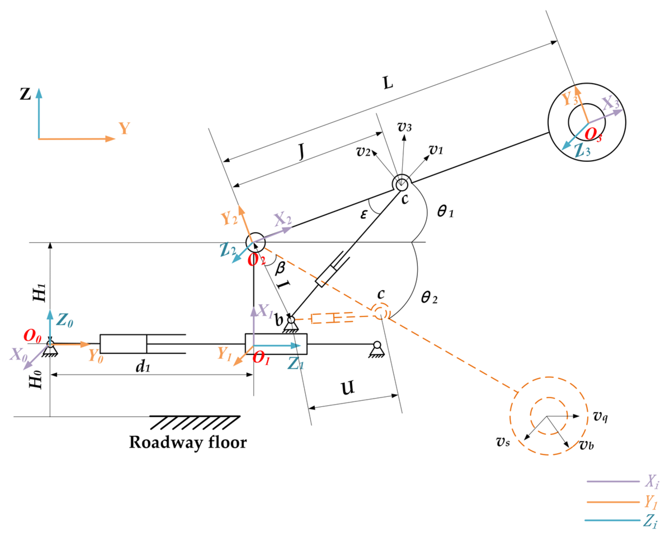
4.1. Kinematic Model of the Cutting Mechanism

The cutting robot primarily relies on the front and rear movement of the movable slide base, the vertical swing of the cutting arm, and the rotation of the cutting drum to perform the cutting of the roadway cross-section. The YOZ plane is selected as the reference plane, and the kinematic model of the cutting robot mechanism is developed using the improved D–H matrix [20], as illustrated in Figure 8. The kinematic parameter of the cutting robot are shown in Table 3.
α1 represents the rotation angle about the common perpendicular axis X1 from the joint axis i−1 to the joint axis i.
a1 is the length of the common perpendicular axis between the joint axis i−1 and the joint axis i.
θi represents the rotation angle about Zi between the common perpendicular axes ai−1 and ai.
di is the distance moved along Zi along the common perpendicular axes ai−1 and ai.
The following velocities and angles are defined:
v1 is the output velocity of the hydraulic cylinder driving the cutting arm.
v2 is the component of the absolute velocity of point c, located on the cutting arm.
v3 is the absolute velocity of point c, which represents the motion of the cutting arm.
vs is the angular velocity of the cylinder as it pivots around O3 under the action of O2.
vq is the linear feeding velocity of the hydraulic cylinder.
vb is the resultant cutting velocity of the drum, determined by the combined effects of vs and vq.
Lastly, the angles ε and β are defined as follows:
ε is the inclination angle formed between the cutting arm and the height adjustment cylinder during operation.
β is the angle formed between the cutting arm at its lowest position and the line segment O2b.
(1) Forward Kinematics of the Robot
According to the principle of the improved D–H matrix and the corresponding structural parameters, the coordinate transformation formula between two adjacent coordinate systems is derived as follows:
T i i 1 = R o t ( x , α i 1 ) T r a n s ( x , a i 1 ) R o t ( z , θ i ) T r a n s ( z , d i )
where Rot(x, αi−1) represents a rotation about the Xi axis by an angle of α1. Trans(x, a i−1) describes a translation along the Xi axis by a distance of a1. Rot(z,iθ) represents a rotation about the Zi axis by an angle of θi. Trans(z,di) describes a translation along the Zi axis by a distance of di. The homogeneous transformation matrices of the adjacent two links are sequentially multiplied to derive the forward kinematics equation of the robot. To simplify the notation in the resulting equation, cos θi and sin θi are abbreviated as si and ci, respectively.
T 0 3 = 0 0 1 a 0 d 2 d 3     c 2 s 3 + c 3 s 2 c 2 c 3 s 2 s 3   0   d 1 + a 2 s 2 s 2 s 3 c 2 c 3 c 2 s 3 + c 3 s 2   0 a 1 a 2 c 2 0 0 0 1 = n x o x a x p x n y o y a y p y n z o z a z p z 0 0 0 1
According to the above homogeneous transformation matrix operation, the forward kinematics matrix of the cutting robot can be obtained. From Equation (8), it is evident that the position coordinates of the cutting drum’s center point relative to the roadway’s spatial coordinate system are given as P = [Px,Py,Pz]T.
(2) Inverse Kinematics of the Robot
Determine all joint variables of the cutting robot based on the specified end-effector position and orientation of the cutting drum. Based on the homogeneous transformation matrix representation of the system, the corresponding inverse transformation matrix is derived as follows:
T 1 1 0 = 0 0 1 0 1 0 0 a 0 0 1 0 d 1 0 0 0 1
Equation (6) is left-multiplied by T 1 0 1 on the left side, and the joint variable solutions are derived by equating the corresponding elements on both sides of the equation and are expressed as follows:
d 1 = p y a 1 s 2 θ 1 = π / 2 θ 2 = a r c s i n p y d 1 a 1 θ 3 = 0
The swing of the cutting arm is primarily driven by the flow of hydraulic oil into the hydraulic cylinder, thus causing the cutting arm to oscillate. The stroke of the hydraulic cylinder determines the angular range of rotation of the cutting arm. Using the kinematic model of the cutting mechanism as a basis, the mathematical relationship between the stroke of the height adjustment cylinder and the corresponding rotation angle is derived through geometric analysis.
The cutting arm rotates around the axis passing through O2. Point b represents the connection point between the height adjustment cylinder and the movable slide base, and point c represents the connection point between the height adjustment cylinder and the cutting arm. With θ2 = 0° as the initial state, where it is assumed that O2b = I and O2c = J, the initial state defines the length of the hydraulic cylinder as bc = U. When the cutting arm rotates upward by an angle θ2, the height adjustment cylinder extends by a length of l.
According to the mathematical relationship between the variables, the extension length l of the height adjustment hydraulic cylinder when the cutting arm rotates upward by an angle θ2 is derived as follows:
l = I 2 + J 2 2 I J c o s θ 2 + a r c c o s I 2 + J 2 U 2 2 I J U
When the cutting robot cuts coal, the height adjustment cylinder first lifts the cutting arm, positioning the drum at the top of the coal wall. While the cutting drum rotates, the feed cylinder drives the drum to penetrate into the coal face. After the cutting drum reaches the designed cutting depth, the combined action of the feed cylinder and the height adjustment cylinder enables the cutting drum to complete the rectangular cross-sectional cutting.
The cutting arm rotates about the mounting hinge center O2, which is connected to the sliding table, under the drive of the height adjustment cylinder. The swing velocity of the endpoint c of the cutting arm is the resultant velocity derived from the linear velocity of the height adjustment cylinder and the angular velocity of the cutting arm swing. The position of the various parts of the cutting mechanism at the lowest position of the cutting drum is illustrated in Figure 8.
The instantaneous center of velocity method [21] and the vector analysis of velocity composition and decomposition [22] are used to derive the relationship between the hydraulic cylinder drive velocity v3, the cutting arm swing velocity vs, and the cutting drum traction velocity vb as follows:
v s = v 3 O 2 b ¯ 2 + O 2 c ¯ 2 2 O 2 b ¯ O 2 c ¯ c o s ( β + θ 2 ) v b = v s + v q

4.2. Kinematic Analysis of Cutting Mechanisms

By integrating the results derived using the parameter-solving methodology proposed in this paper with the parameters determined in the team’s prior research on the cutting robot [23], I = 646 mm and J = 1088 mm are determined to be the key parameters of the cutting mechanism, and the corresponding 3D model of the cutting robot is illustrated in Figure 9.
The simulated cutting robot was used to cut inter-panel coal pillars with a mining height of 4000 mm, 3000 mm, and 2500 mm, operating at a velocity of vb = 3 m/min. The variation ranges of the lengths of the feed cylinder O0b and the height adjustment cylinder bc are illustrated in the corresponding figure.
Figure 10 shows that, during the rectangular cutting process of the roadway, the length of the feed cylinder O0b reaches a maximum value of 2088 mm and a minimum value of 866 mm, while the length of the height adjustment cylinder bc reaches a maximum value of 1147 mm and a minimum value of 509 mm. This result serves as a reference for determining the hydraulic drive parameters of the cutting robot.

5. Dynamic Analysis of the Cutting Robot

5.1. Mathematical Model of the Dynamics of the Cutting Drum

The cutting robot fractures coal and rock using a transverse-axis cutting drum. During this process, the cutting power and drum speed are typically constant and cannot be adjusted in real time. The main resistance torque acting on the drum originates from the resultant moment generated by the cutting teeth fracturing the surrounding rock. Key factors, such as cutting velocity, drum rotational speed, and depth of cut, significantly influence the resultant moment, thereby affecting both the mining efficiency and safety of inter-panel coal pillar operations. To prevent safety issues, such as robot overload caused by improper parameter settings (e.g., cutting velocity or depth of cut), it is necessary to analyze the resistance torque induced by the cutting teeth under various working conditions.
The dynamic parameters involved in the drum’s cutting of the surrounding rock include the following:
  • FR—Cutting resistance experienced by the cutting teeth on the horizontal-axis cutting head during coal and rock cutting;
  • Fk—Traction resistance acting on the cutting teeth;
  • Tm—Load torque acting on the cutting drum during the cutting of surrounding rock;
  • P—Driving power required by the cutting drum;
  • ap—Theoretical cutting depth range for the cutting drum when cutting surrounding rocks of varying hardness.
The second calculation method from [24] was adopted to derive the relationships among these parameters. The dynamic relationships of the cutting drum are expressed in Equation (11).
h = 2 v b m a x π n N j A p = 100 ~ 150 f F R = A p h K T N K S K S N + μ P K N F k = K n F R T m = q F R R P = 1000 T p m m a x 9550 η a p = T o u t q F R K a p
In the formula, the following obtain:
  • h —Average cutting thickness (in meters);
  • vbmax—Maximum cutting velocity of the drum;
  • n—Rotational speed of the cutting drum;
  • Nj—Number of cutting teeth on the cutting drum located on the same cutting line;
  • A p —Average cutting resistance encountered in the coal seam (in KN/m);
  • f—Coal–rock firmness coefficient;
  • KTN—Shape coefficient of cutting teeth, ranging from 1.5 to 2.5 for spade teeth and 1.1 to 1.5 for radial teeth;
  • KS—Combined action coefficient of the cutting teeth, typically ranging between 0.7 and 0.9;
  • KSN—Stress state coefficient of coal and rock, commonly assumed to be 1;
  • μ p —Friction coefficient between cutting teeth and coal–rock interface, typically μ = 0.3;
  • KN—Radial force influence coefficient on blunt teeth, with a typical value of 0.5;
  • Kn—Ratio of traction force to cutting force, typically 0.6 for brittle coal and 0.7 for viscous coal;
  • q—Actual number of cutting teeth engaged in the rock, expressed as q = q0e/(πDₒp);
  • q0—The total number of cutting teeth potentially engaging the rock, given a tooth thickness of a and a maximum cutting depth of e;
  • Kp—Load factor of the drum’s drive system;
  • η —Mechanical transmission efficiency;
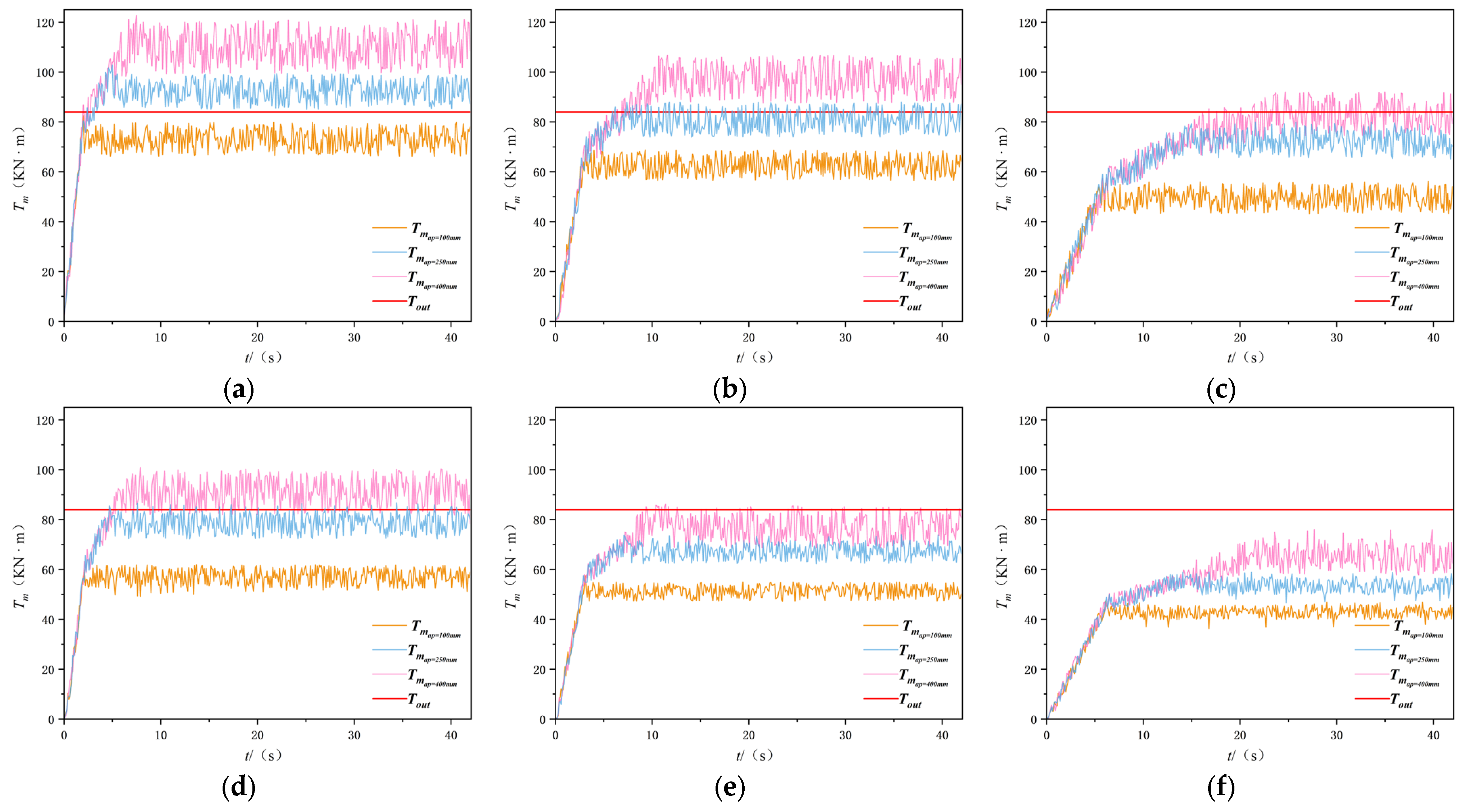
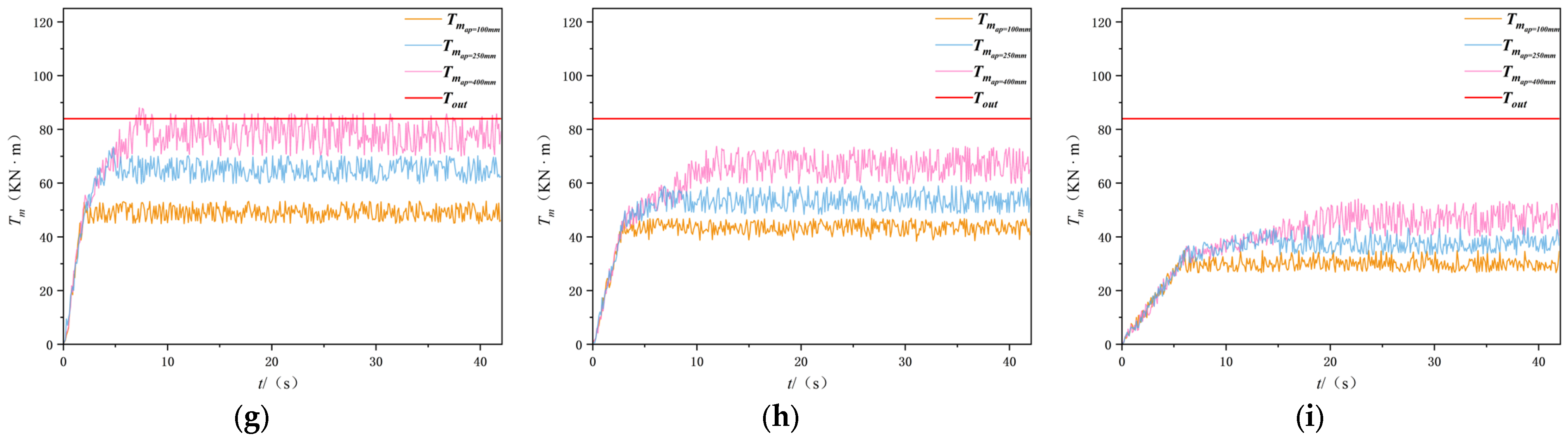
  • Kap—Fluctuation coefficient of the cutting force, which exhibits a positive correlation with the rock strength coefficient.
During the cutting process of the cutting drum, the cutting drum rotation speed n is constant, while vb is assumed to be constant in theory. From the above formula, it is evident that the cutting resistance FR of the cutting teeth varies within a range and is positively correlated with the average cutting resistance of the coal seam ( A p ), increasing with the increase in A p .
The theoretical cutting depth ap is inversely proportional to the cutting resistance FR of the cutting teeth, decreases as FR increases, and is constrained by the condition apR, where R represents the maximum allowable cutting depth.

5.2. Simulation Modeling of Cutting Robot Dynamics

Based on the analysis of existing mining equipment, a cutting drum with a diameter of D = 1 m was selected and equipped with 120 conical pick cutters (30 mm in diameter), with one cutter per helical line. The cutting drum’s design parameters include a maximum rock hardness rating of f5, a drum width of 4 m, a rotational speed of n0 = 30 r/min, and a maximum cutting velocity of vb = 3 m/min. The drum is driven by a 270 kW motor with a maximum torque output of 85 kN·m. Existing studies [25] demonstrate that these parameters satisfy operational requirements for a maximum cutting velocity of 3 m/min and a maximum depth of cut of 400 mm. Therefore, the simulation focuses on the effects of cutting velocity, drum rotational speed, and depth of cut on the drum’s load torque, excluding vibration and deformation-induced structural damage.
From Equation (11), the following maximum cutting depth values were determined under different cutting velocity and rock hardness levels:
(1)
For vb = 3 m/min, the maximum cutting depths for f5, f3, and f2 rocks are 117 mm, 188 mm, and 359 mm, respectively;
(2)
For vb = 2 m/min, the maximum depths increase to 148 mm, 411 mm, and 438 mm, respectively;
(3)
For vb = 1 m/min, the maximum depths are 210 mm, 418 mm, and 500 mm, respectively.
Given that the inter-panel coal pillar’s maximum rock hardness is f3, load characteristics of the drum are analyzed under varying cutting velocity and depths for rocks of hardness levels f5, f3, and f2. The experimental parameters are listed in Table 4.
A box with dimensions of 4.5 m × 1.0 m × 4.0 m is established in the DEM software EDEM2022 and filled with coal and rock particles. A particle model is developed using the particle parameters provided in [26]. An additional box is constructed above the coal seam, and a specific force is applied via the MCU (Mechanical Contact Unit) tool to simulate the roof pressure exerted on the coal and rock. The formula used to calculate the roof pressure per unit area is provided in [27,28]:
P c = γ z h k 2 + D γ L L 0 k 1 2 L k 1 0 3
where the following obtain:
  • Pc—Roof pressure (in Newtons, N);
  • k1—Dynamic pressure coefficient;
  • k2—Coefficient of roof sag and rib spalling;
  • γZ—Density of the immediate roof rock (in g/mm3);
  • γL—Density of the main roof rock (in g/mm3);
  • Lk—Unsupported roof span (in mm);
  • L0—Initial pressure step span of the main roof (in mm);
  • h′—Thickness of the immediate roof strata (in mm);
  • D′—Thickness of the main roof strata (in mm).
Material parameters are adopted from [26,29], with specific properties shown in Table 5. Contact parameters between materials are added according to the method in [30]. The restitution coefficient, static friction coefficient, and dynamic friction coefficient for coal–coal and coal–drum interactions are set as follows:
(4)
Coal–coal: restitution coefficient = 0.5, static friction coefficient = 0.5, dynamic friction coefficient = 0.01;
(5)
Coal–drum: restitution coefficient = 0.5, static friction coefficient = 0.45, dynamic friction coefficient = 0.01.
The Hertz–Mindlin bonding model is employed to bond particles, which transmits normal stress, shear stress, and moments between contacting particles while accommodating certain tangential and normal movements [30]. Bonding parameters for particles under various rock hardness levels are calibrated based on the experimental results in [31,32], as shown in Table 6.
The coupled drum–rock simulation model is illustrated in Figure 11. By varying the drum’s cutting velocity and depth of cut, the drum is driven along a cutting trajectory to fracture rocks of different hardness levels. Load torque data for the drum are collected at intervals of 0.1 s to analyze its behavior under different working conditions. This modeling approach has been validated by comparing the simulation results with practical cutting performance metrics, demonstrating its adequacy in capturing the dynamics of the cutting drum and its interactions with the surrounding rock [29].

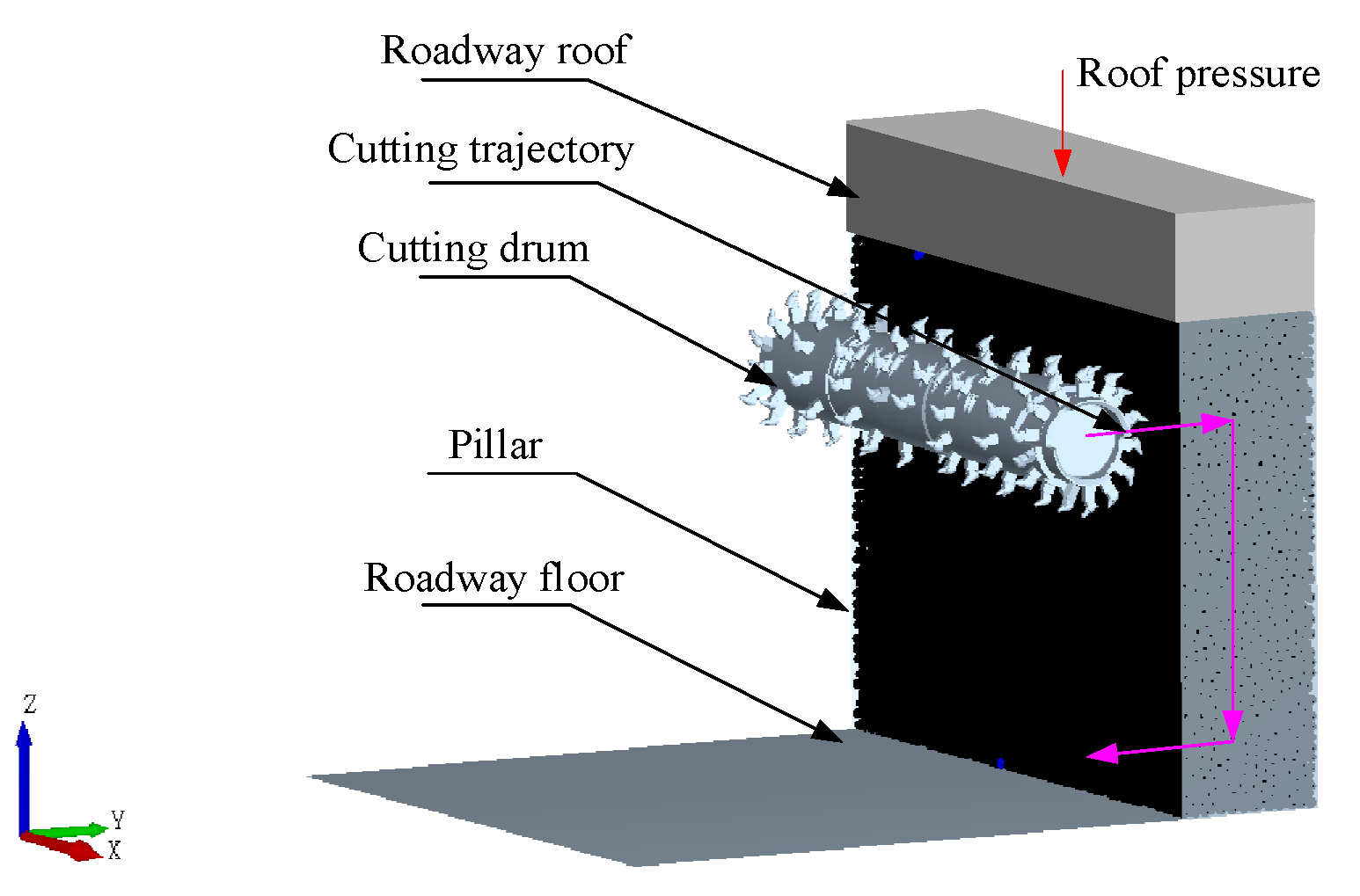
5.3. Dynamic Simulation Analysis of a Cutting Robot

The load torque data of the cutting drum during the cutting process were obtained through the post-processing module of the DEM software. The results are shown in Figure 12. The pink curve in the figure shows the load torque Tm of the drum when ap = 400 mm, the blue curve shows the load torque Tm of the drum when ap = 100 mm, and the yellow curve corresponds to the same cutting depth of ap = 100 mm. The red line in the figure shows the maximum output torque. The figure shows the trend of the load torque of the drum over time under cutting depths of 100 mm, 250 mm, and 400 mm for nine different working conditions.
As demonstrated in [26], where a transverse cutting mechanism was used to continuously cut the coal seam, the simulation results under the same depth of cut exhibit a high degree of consistency with the trends reported in the literature, thereby verifying the accuracy of the established drum–surrounding rock coupling simulation model. By comparing the nine operating conditions in the figure, it can be observed that the helical distribution of cutting picks on the drum causes an increase in the number of picks simultaneously in contact with the coal seam as the depth of cut increases. This results in an overall trend of increasing fluctuations in the drum’s load torque over time. Once the depth of cut reaches its maximum, the number of picks simultaneously in contact with the surrounding rock stabilizes, leading to torque fluctuations within a specific range. Additionally, as the hardness of the coal and rock increases, the cutting resistance experienced by the drum increases, causing the range of torque fluctuations to expand at the same cutting velocity. A comparison of the nine working conditions in the figure shows that the load torque of the drum initially increases with fluctuations and subsequently stabilizes within a specific range over time.
In the presence of hard surrounding rock, the crushing process results in an increased number of surrounding rock particles interacting with the drum and cutting teeth. This occurs due to excessive cutting velocity and cutting depth, and as a result, the reaction force exerted by the coal seam increases. Consequently, the drum load torque under the following five working conditions exceeds the maximum output torque significantly, accompanied by substantial fluctuations: ① f5, vb = 3 m/min, ap = 400 mm; ② f5, vb = 3 m/min, ap = 250 mm; ③ f5, vb = 2 m/min, ap = 400 mm; ④ f5, vb = 1 m/min, ap = 400 mm; ⑤ f3, vb = 3 m/min, ap = 400 mm.
By decreasing the feed velocity and cutting depth, the drum load torque is observed to fluctuate around the maximum output torque under the following four conditions: ① f5, vb = 2 m/min, ap = 250 mm; ② f3, vb = 3 m/min, ap = 250 mm; ③ f3, vb = 2 m/min, ap = 400 mm; ④ f2, vb = 3 m/min, ap = 400 mm.
It is demonstrated that, within the specified operational parameters, the cutting drums are capable of executing cutting operations on the target surrounding rock. After comprehensively considering factors such as cutting efficiency, it was determined that the following obtained:
When mining the surrounding rock of f5, the maximum engaging speed is 1 m/min, and the maximum cutting depth is 250 mm; when mining the surrounding rock of f3, the maximum engaging speed is 1 m/min, and the maximum cutting depth is 400 mm; when mining the surrounding rock of f2, the maximum feed speed is 2 m/min, and the maximum cutting depth is 400 mm.

6. Conclusions

(1) To meet the mining requirements of the ’excavation–backfill–retention’ tunneling method applied to inter-panel coal pillars, the interactive mapping relationships between the demand, function, and structure domains of the cutting robot were thoroughly analyzed. By employing an interactive design approach, an interactive mapping model for the cutting robot within the inter-panel coal pillar mining system was constructed, a conceptual model of the cutting robot was developed, and it was concluded that the cutting robot employs the method of ‘horizontal-axis cutting and segmented mining’ to mine the inter-panel coal pillar.
(2) A structural parameter model of the cutting robot was developed, and its relationship with surrounding rock parameters was analyzed. A hierarchical solution method for determining the structural parameters of the cutting robot was introduced. This method leveraged the local search method and multi−objective genetic algorithm principles to solve the main parameters of the cutting robot under target operating conditions. Based on this approach, the main structural parameters of the cutting robot were successfully determined. The final step in the research process was the development of a 3D model of the cutting robot using the obtained solution results. The kinematic characteristics of the cutting mechanism were analyzed to determine the interrelationship between the motion parameters. The length range of the feed cylinder and the height adjustment cylinder was determined through simulation, providing critical parameter references for cylinder selection.
(3) A simulation model of the coupling between the drum and the surrounding rock was developed using the discrete element method (DEM). The study examined the relationships among coal–rock hardness, drum load, and cutting depth. The simulation analysis was conducted to analyze the load characteristics of the cutting drum under varying coal–rock firmness coefficients, cutting depths, and cutting velocity. The study aimed to identify the maximum cutting velocity and depth for cutting surrounding rocks with firmness coefficients of f5, f3, and f2 at the rated drum driving power. This theoretical framework offers theoretical guidance for trajectory planning and adaptive control of the cutting robot.
(4) This paper has conducted foundational theoretical research on the modeling and analysis of the cutting robot. Building on this work, the next phase will involve the following: (a) developing a complete system dynamics model using the Lagrangian method to analyze the impact of vibration on equipment durability; (b) employing finite element analysis to further assess equipment reliability by identifying components prone to deformation during operation, thereby optimizing the cutting robot’s reliability and maintainability; and (c) validating the feasibility of the designed equipment through a combined approach of multi−body dynamics modeling and discrete element method simulations, as well as establishing a control system to investigate its adaptive cutting control strategy.
(5) For experimental validation, a physical prototype system will be constructed based on modular design principles, employing the DH311E three-axis acceleration sensor as the core vibration measurement unit, with sensors installed on the cutting drum, at the hinge of the cutting arm, and at the machine’s center of mass. Multiple groups of coal–rock specimens with varying Pu’s coefficients will be fabricated by mixing coal powder, silicate cement, and polymer binders in different proportions, and a layered compaction process will be applied to ensure the mechanical anisotropy of the specimens. Comparative tests under multiple working conditions will be designed using a computer-controlled module to drive the cutting drum against the coal wall, while a data acquisition system synchronously collects sensor signals for recording experimental data. The collected data will be analyzed to evaluate the influence of vibration on the robot during the mining process.
(6) An experimental environment with a gradient of dust concentration will be established, and multiple regression analysis will be employed to investigate the impact of dust on the robot. Based on failure mode analysis, preventive maintenance strategies and fault-tolerant control schemes targeting extreme operating conditions will be developed, thereby providing both theoretical support and experimental evidence to enhance the engineering applicability of the cutting equipment.

Author Contributions

Conceptualization, H.M. and W.C.; methodology, W.C., C.W. and X.X.; software, W.C.; validation, W.C., L.X. and Q.M.; formal analysis, H.S.; investigation, Z.Y.; resources, W.C.; data curation, J.C.; writing—original draft preparation, W.C.; writing—review and editing, Y.G. and H.W.; visualization, K.M.; supervision, H.M.; project administration, H.M.; funding acquisition, H.M. and C.W. All authors have read and agreed to the published version of the manuscript.

Funding

This research was funded by the Key Technologies Research and Development Program of China, grant number 2023YFC2907600 and the Key Research and Development Projects of Shaanxi Province, grant number 2023-LL-QY-03.

Data Availability Statement

The original contributions presented in the study are included in the article, and further inquiries can be directed to the corresponding authors.

Conflicts of Interest

The authors declare no conflicts of interest.

References

  1. Wang, S.M.; Liu, L.; Zhu, M.B.; Shen, Y.J.; Shi, Q.M.; Sun, Q.; Fang, Z.Y.; Ruan, S.S.; He, W.; Yang, P.; et al. New way for green and low-carbon development of coal industry under the target of “dual-carbon”. J. China Coal Soc. 2024, 49, 152–171. [Google Scholar] [CrossRef]
  2. Wang, S.M.; Liu, L.; Zhu, M.B.; Wei, B.N.; Zhuang, D.D.; Qu, H.S.; He, W.; Shao, C.C.; Xia, L.; Zhou, J. Scientific problems and technology of the integration of “excavation-backfill-retention” of section coal pillar and mining roadway. J. China Coal Soc. 2024, 49, 3291–3315. [Google Scholar] [CrossRef]
  3. Ralston, J.C.; Hargrave, C.O.; Dunn, M.T. Longwall automation: Trends, challenges and opportunities. Int. J. Min. Sci. Technol. 2017, 27, 733–739. [Google Scholar] [CrossRef]
  4. Wang, B.K. Current status and trend analysis of roadway driving technology and equipment in coal mine. Coal Sci. Technol. 2020, 48, 1–11. [Google Scholar] [CrossRef]
  5. Yang, J.J.; Zhang, Q.; Wang, C.; Chang, B.S.; Wang, F.; Wang, X.L.; Wu, M. Status and development of robotization research on roadheader for coal mines. J. China Coal Soc. 2020, 45, 2995–3005. [Google Scholar] [CrossRef]
  6. Zhang, Y.L.; Wang, B.K.; Zhang, X.F.; Li, Q.F. Forty years’development and future prospect on mechanized short-wall mining technology with continuous miner in China. J. China Coal Soc. 2021, 46, 86–99. [Google Scholar] [CrossRef]
  7. Ma, J.G. Research on development status of short-wall mechanized mining technology of continuous miner. Coal Sci. Technol. 2020, 48, 180–188. [Google Scholar] [CrossRef]
  8. Kang, H.P.; Jiang, P.F.; Wang, Z.Y.; Zhang, X.F.; Liu, C.; Luo, C.; Wei, R.Z.; Guo, J.C.; Chen, Z.L.; Wang, R.; et al. Coal roadway rapid driving technology and equipment with integrated drilling and anchoring and its application. J. China Coal Soc. 2024, 49, 131–151. [Google Scholar] [CrossRef]
  9. Ma, H.W.; Wang, S.B.; Mao, Q.H.; Shi, Z.W.; Zhang, X.H.; Yang, Z.; Cao, X.G.; Xue, X.S.; Xia, J.; Wang, C.W. Key common technology of intelligent heading in coal mine roadway. J. China Coal Soc. 2021, 46, 310–320. [Google Scholar] [CrossRef]
  10. Xue, L.M.; Ma, H.W.; Wang, C.W.; Zhang, H. Cutting ability of cutting robot in shield intelligent tunneling system. J. Xi’an Univ. Sci. Technol. 2023, 43, 779–786. [Google Scholar] [CrossRef]
  11. Hu, J. Analysis of the mining process of a double-stage rocker single-drum shortwall coal miner. Coal Technol. 2023, 42, 232–234. [Google Scholar] [CrossRef]
  12. Kang, H.P.; Xu, G.; Wang, B.M.; Wu, Y.Z.; Jiang, P.F.; Pan, J.F.; Ren, H.W.; Zhang, Y.J.; Pang, Y.H. Forty years development and prospects of underground coal mining and strata control technologies in China. J. Min. Strat. Control Eng. 2019, 1, 013501. [Google Scholar] [CrossRef]
  13. Sun, Z.L.; Wang, K.F.; Gu, P.H. Review and prospect for design theory and methodology research. J. Mech. Eng. 2024, 60, 2–20. [Google Scholar]
  14. Bao, H.; Gao, Y.F.; Wan, C.; Liu, Z.F.; Zhu, L.B.; Wang, Z. Interactive design and knowledge transfer research of product easy disassembly for multi−stage recycling needs. J. Mech. Eng. 2024, 60, 257–267. [Google Scholar]
  15. Ma, H.W.; Wang, J.K.; Wang, C.W. Fuzzy evaluation method of modular variable weight for temporary supporting device in coal mine roadway. J. Xi’an Univ. Sci. Technol. 2023, 43, 576–585. [Google Scholar]
  16. Yuan, S.Z.; Gao, H.N.; Wang, W.; Qu, Y.; Liu, X.W.; Li, K. Multi−image evaluation for human-machine interface based on Kansei engineering. Chin. J. Eng. Des. 2017, 24, 523–529. [Google Scholar]
  17. Janjua, A.N.; Shaefer, M.; Amini, S.H.; Noble, A.; Shahab, S. Vibrational energy transmission in underground continuous mining: Dynamic characteristics and experimental research of field data. Appl. Energy 2024, 354. [Google Scholar] [CrossRef]
  18. Aarts, E.; Lenstra, J.K. Local Search in Combinatorial Optimization, 1st ed.; Princeton University Press: Princeton, NJ, USA, 1997; pp. 15–78. [Google Scholar]
  19. Deb, K. Multi−Objective Optimization Using Evolutionary Algorithms, 1st ed.; Wiley: Chichester, UK, 2001; pp. 203–256. [Google Scholar]
  20. Craig, J.J. Introduction to Robotics: Mechanics and Control, 3rd ed.; Pearson: Upper Saddle River, NJ, USA, 2005. [Google Scholar]
  21. Beer, F.P.; Johnston, E.R. Vector Mechanics for Engineers: Dynamics, 12th ed.; McGraw-Hill: New York, NY, USA, 2019; pp. 210–235. [Google Scholar]
  22. Meriam, J.L.; Kraige, L.G. Engineering Mechanics: Dynamics, 7th ed.; Wiley: Hoboken, NJ, USA, 2012. [Google Scholar]
  23. Ma, H.; Xue, L.; Wang, C.; Cui, W. Research on the cutting control method of a shield-type cutting robot. Actuators 2024, 13, 490. [Google Scholar] [CrossRef]
  24. Li, G.X. Dynamic parameters of roadheader and physical and mechanical properties of coal and rock. J. China Coal Soc. 1993, 4, 71–77. [Google Scholar]
  25. Wei, J.; Wu, M. Modern Coal Roadheader in China; Coal Industry Press: Beijing, China, 2015; pp. 190–219. [Google Scholar]
  26. Chen, H.Y.; Hai, Q.H.; Wang, C.G.; Zhang, D.S. Simulation and analysis of cutting performance of windlass excavator’s drum under different working conditions. Mech. Des. 2023, 40, 45–53. [Google Scholar] [CrossRef]
  27. Wang, J.H. Development and prospect on fully mechanized mining in Chinese coal mines. Int. J. Coal Sci. Technol. 2014, 1, 153–160. [Google Scholar] [CrossRef]
  28. Wang, J.H.; Yu, B.; Kang, H.P.; Wang, G.; Mao, D.; Liang, Y.; Jiang, P. Key technologies and equipment for a fully mechanized top-coal caving operation with a large mining height at ultra-thick coal seams. Int. J. Coal Sci. Technol. 2015, 2, 97–101. [Google Scholar] [CrossRef]
  29. Zhao, L.J.; Wen, S.J.; Liu, X.N. The influence of simulated particle radius on complex coal seam of drum cutting. Mech. Sci. Technol. Aerosp. Eng. 2020, 39, 52–57. [Google Scholar] [CrossRef]
  30. Su, O.; Akcin, N.A. Numerical simulation of rock cutting using the discrete element method. Int. J. Rock Mech. Min. Sci. 2011, 48, 434–442. [Google Scholar] [CrossRef]
  31. Zhao, L.J.; Wang, Y.D.; Zhang, M.C.; Jin, X.; Liu, H.M. Research on self-adaptive cutting control strategy of shearer in complex coal seam. J. China Coal Soc. 2022, 47, 541–563. [Google Scholar] [CrossRef]
  32. Mao, J.; Liu, X.Y.; Chen, H.Y.; Song, Q.S. Simulation research of shearer drum cutting performance based on EDEM. J. China Coal Soc. 2017, 42, 1069–1077. [Google Scholar] [CrossRef]
Figure 1. The system design for the “excavation–backfill–retention” integrated mining and excavation equipment.
Actuators 14 00175 g001
Figure 2. Interactive mapping model of ‘requirements–functions–structure’ for the cutting robot.
Actuators 14 00175 g002
Figure 3. Principle model of a cutting robot.
Actuators 14 00175 g003
Figure 4. The construction of a parameter analysis model of the cutting robot.
Actuators 14 00175 g004
Figure 5. The analytical model of the structural parameters of the cutting robot and the parameters of the surrounding rock.
Actuators 14 00175 g005
Figure 6. Relationship between roadway height H and changes in robot structural parameters L, A, and R.
Actuators 14 00175 g006
Figure 7. Flow chart of the hierarchical solution process for the structural parameters of the cutting robot.
Actuators 14 00175 g007
Figure 8. Kinematic model of the cutting mechanism.
Actuators 14 00175 g008
Figure 9. Kinematic model of the cutting mechanism.
Actuators 14 00175 g009
Figure 10. Stroke diagram of the rectangular cutting height adjustment cylinder with different mining heights. (a) Mining height 4000 mm. (b) Mining height 3000 mm. (c) Mining height 2500 mm.
Actuators 14 00175 g010
Figure 11. Coupled simulation model of the cutting drum and surrounding rock.
Actuators 14 00175 g011
Figure 12. Simulation results of surrounding rock cutting by drum cutting. (a) f5, vb = 3 m/min. (b) f5,vb = 2 m/min. (c) f5, vb = 1 m/min. (d) f3, vb = 3 m/min. (e) f3, vb = 2 m/min. (f) f3, vb = 1 m/min. (g) f2, vb = 3 m/min. (h) f2, vb = 2 m/min. (i) f2, vb = 1 m/min.
Actuators 14 00175 g012aActuators 14 00175 g012b
Table 1. Characteristics of several major mining equipment.
Mining EquipmentAuxiliary EquipmentTransportation MethodMining HeightMining WidthMain Shortcomings
Real mining machineShuttle car, temporary support equipment, drilling platform, etc.Shuttle car, transfer system≤6 m≤7.7 mLimited mining width
Rapid tunneling systemTemporary support equipment, drilling equipment, etc.Built-in transportation system, transfer system≤8.8 m≤7.5 mLimited mining width
Longwall mining machineScraper conveyorScraper conveyor, transfer system≤5.1 mShortwall panel lengthMining causes boundary coal losses
Continuous minerScraper conveyorScraper conveyor, transfer system≤2 mShortwall panel lengthLow mining height
Table 2. Functional division of major structural components of cutting equipment.
Serial No.Cutting MethodMobility MethodTransportation MethodWorking Face Advancement Method
1Vertical-axis typeCrawler typeBuilt-in loading mechanism + scraper conveyorHydraulic support advancement
2Short horizontal-axis typeSlider shoe typeCoal loader mechanism + scraper conveyor
3Long horizontal-axis typePush–pull typeShuttle car + transfer machineAutonomous advancement
4Single oscillating pick drumWheel typeBuilt-in loading mechanism + transfer machine
Table 3. Cutting robot kinematic parameter table.
i−1iαi−1ai−1θidi
01π/20−π/2480~(480 + C)
12−π/2500(−π/2) − θ2, (−π/2) + θ10
2303000θ30
Table 4. Parameter settings for different analogue groups.
NumberfN (RPM)vb (m/min)ap/mm
1f5, f3, f2303100
200
400
2f5, f3, f2302100
200
400
3f5, f3, f2301100
200
400
Table 5. Material parameters.
MaterialPorosityElastic Modulus (MPa)Density (kg/m3)
f1 coal0.2718101953
f2 coal0.3033272056
f3 coal0.2652732208
Steel0.317 × 1047800
Table 6. Contact parameters.
Particle Bonding Parametersf1 Coalf2 Coalf3 Coal
Normal stiffness per unit area (10⁸ N/m3)1.14821.28531.4028
Shear stiffness per unit area (10⁸ N/m3)8.54149.945711.1960
Normal stress per unit area (MPa)7.859210.254013.9510
Shear stress per unit area (MPa)6.92177.01527.2548
Disclaimer/Publisher’s Note: The statements, opinions and data contained in all publications are solely those of the individual author(s) and contributor(s) and not of MDPI and/or the editor(s). MDPI and/or the editor(s) disclaim responsibility for any injury to people or property resulting from any ideas, methods, instructions or products referred to in the content.

