Article

Adaptive Super-Twisting Controller-Based Modified Extended State Observer for Permanent Magnet Synchronous Motors

1
School of Energy and Power Engineering, Chongqing University, Chongqing 400044, China
2
China Merchants Testing Vehicle Technology Research Institute, Chongqing 401122, China
3
College of Mechanical and Vehicle Engineering, Chongqing University, Chongqing 400044, China
*
Author to whom correspondence should be addressed.
Actuators 2025, 14(4), 161; https://doi.org/10.3390/act14040161
Submission received: 8 February 2025 / Revised: 17 March 2025 / Accepted: 19 March 2025 / Published: 23 March 2025
(This article belongs to the Section Control Systems)

Abstract

:
A novel sliding mode control (SMC) strategy incorporating an adaptive super-twisting algorithm is developed for permanent magnet synchronous motors (PMSMs), effectively mitigating high-frequency chattering while enhancing external disturbance rejection capabilities. Initially, a sliding surface is crafted based on the dynamic characteristics of the PMSM and real-time feedback. The super-twisting algorithm is subsequently applied adaptively to dynamically adjust the control effort required to maintain the sliding mode state, thereby ensuring precise and prompt intervention to uphold system stability and enhance response speed. Additionally, in light of operational challenges such as road-induced load disturbances, a Lyapunov-based disturbance observer is proposed for precise load torque estimation in PMSM systems. The efficacy of the proposed control and observation methods is substantiated through a hardware-in-the-loop experiment test, demonstrating that the developed sliding mode controller, leveraging the adaptive super-twisting algorithm, exhibits superior tracking and disturbance rejection capabilities, reduces steady-state current error, and bolsters system parameter robustness, and the modified extended state observer (MESO) exhibits commendable estimation performance.

1. Introduction

The growing demand for high-performance motor drives in industries such as electric vehicles, renewable energy, and industrial automation highlights the need for control systems that can operate efficiently under dynamic conditions, including parameter variations, load disturbances, and power supply fluctuations. Traditional control methods often struggle to meet these requirements, emphasizing the need for innovative solutions offering robustness, adaptability, and computational efficiency [1,2]. This need for advanced control systems is particularly evident with the rising adoption of PMSMs across sectors like new energy vehicles, rail transportation, aerospace, and wind power generation. The motor’s simple design, high operational efficiency, and substantial power density contribute to its widespread use [3,4,5,6], making the study of control methods for PMSMs increasingly critical to meet the diverse demands of these applications [7,8,9,10,11].
Furthermore, the increasing complexity of modern systems and the integration of Internet of Things (IoT) technologies require motor drives to exhibit even more adaptability and real-time decision-making capabilities [12]. As industries implement IoT and smart technologies, motor systems are expected to adjust quickly to varying conditions, improving the overall system’s efficiency and responsiveness [13]. This shift towards smarter systems further emphasizes the need for advanced control strategies that can process more data and optimize motor drive performance in real time, ensuring minimal energy consumption and reduced system downtime [14,15]. The integration of intelligent systems with PMSMs has become a critical factor for sectors such as robotics, where quick adaptation to environmental changes is necessary for accurate and stable operations [16].
However, despite the advancements in traditional control strategies such as Field-Oriented Control (FOC) and Direct Torque Control (DTC), several limitations persist. For instance, FOC relies heavily on Proportional–Integral (PI) controllers, which struggle to achieve both rapid response and minimal overshoot, particularly in dynamic industrial environments [17,18,19,20,21,22]. Similarly, DTC, while structurally simple, suffers from significant torque ripple and variable switching frequencies, especially at low speeds [23,24,25,26,27].
To address these challenges, recent research has focused on advanced nonlinear control strategies, such as adaptive control and Model Predictive Control (MPC). While these methods offer improved performance, they are often limited by design complexity, computational demands, or reduced robustness under parameter variations and external disturbances [28,29,30,31,32,33,34,35,36,37,38,39]. Among these, SMC has gained significant attention due to its robustness against uncertainties and disturbances [40,41,42,43,44]. However, traditional SMC is plagued by high-frequency oscillations, which can destabilize the system and damage motor drive circuitry [45,46,47,48].
By addressing the limitations of existing control strategies in PMSM systems, our work introduces a novel adaptive super-twisting control (ATSC) strategy that synergistically combines adaptive control principles with the super-twisting algorithm to achieve rapid, precise, and robust performance. Specifically, the proposed approach features two key innovations: an ATSC that dynamically adjusts control parameters to maintain stability under uncertain conditions, and a modified extended state observer (MESO) based on Lyapunov stability theory for accurate load torque estimation and disturbance mitigation [49,50]. This integrated framework overcomes traditional challenges in disturbance rejection and parameter sensitivity while enhancing transient response characteristics. The combination of adaptive control’s self-optimizing capability with the MESO’s enhanced observation precision creates a comprehensive solution that advances the theoretical understanding of nonlinear control systems. Moreover, the strategy demonstrates practical viability through improved robustness against load variations and system uncertainties, offering industrial applications [51,52,53] a reliable solution for high-performance motor drives that bridges the gap between theoretical innovation and engineering implementation.
This novel approach aims to enhance the performance and robustness of permanent magnet synchronous motors (PMSMs) by effectively dealing with uncertainties and disturbances. This research is motivated by the need for more efficient, precise, and reliable control methods for PMSMs, which are critical in various industrial applications. By addressing these issues, this study contributes to advancing motor control technology, ensuring improved operational efficiency and dynamic response. The design of the ASTC strategy is driven by the need to address the inherent limitations of traditional control methods in PMSM systems, particularly in dynamic and uncertain industrial environments. The ATSC integrates adaptive control with the super-twisting algorithm to achieve both rapid response and robustness. The adaptive control mechanism dynamically adjusts control parameters in real time to maintain system stability, even under disturbances and parameter variations. Meanwhile, the MESO enhances the system’s ability to estimate load torque and reject disturbances accurately. This integrated approach enhances both the theoretical understanding and practical implementation of nonlinear control systems for PMSMs, making it a viable solution for high-performance motor drives in modern industries.
The remainder of this paper is organized as follows: Section 2 introduces the unified PMSM model. Section 3 details the design of the adaptive super-twisting sliding mode controller. Section 4 discusses the enhanced ESO. Section 5 verifies the efficacy of the proposed control approach through simulation, and Section 6 concludes this paper.

2. PMSM Mathematical Model

The specific mathematical models of the PMSM were chosen for this task due to their ability to accurately capture the dynamic behavior and control characteristics of the motor. These models provide a comprehensive representation of the electrical, mechanical, and magnetic properties of the PMSM, which are essential for designing effective control strategies. The PMSM models used in this study offer a clear description of the system dynamics, including the torque production mechanism, electrical dynamics, and mechanical motion of the rotor.
In addition to their accuracy, the selected models also provide a balance between complexity and computational efficiency, making them suitable for real-time control applications. Computational efficiency is crucial for implementation in embedded systems where processing power is limited and real-time performance is required. Therefore, the chosen models ensure that the control strategies can be applied effectively while maintaining system stability and performance.
A three-phase permanent magnet synchronous motor (PMSM) is a strong coupling and complex nonlinear system. It is important to establish a proper mathematical model to describe its motion for the accurate control of the motor. According to the different rotor structures, the three-phase PMSM can be divided into two types, which are built-in and surface mount. The air gap magnetic density waveform of the surface-mounted three-phase PMSM is close to the sine wave distribution, which makes the motor performance higher. Although the dynamic performance of the built-in three-phase PMSM is better than that of the surface-mounted three-phase PMSM, the manufacturing cost and magnetic leakage coefficient are greater than those of the surface-mounted three-phase PMSM. Therefore, this paper chooses to carry out mathematical modeling on the surface-mounted three-phase PMSM. In order to simplify the complexity of the model and improve the readability of the model, the following assumptions are made:
(1)
The three-phase stator current of the motor is a sine wave, the phase difference is 120 degrees, and the amplitude is equal.
(2)
The magnetic saturation phenomenon of the iron core is ignored.
(3)
The eddy current phenomenon is ignored, and there is no other form of hysteresis loss.
In motor control, the mathematical model under the d-q axis is commonly used for study, and the A-B-C coordinate mathematical model is transformed into the d-q axis state equation through Clark and Park transformations:
u d = R s + L d d i d d t ω e L q i q u q = R s i q + L q d i q d t + ω e L d i d + ψ f
The electromagnetic torque equation is as follows:
T e = 3 2 p i q i d L d L q + ψ f
The mechanical motion equation is as follows:
T e = T L + J d d t ω m + B ω m
Here, u d and u q denote the d-q axis stator voltages, while i d and   i q represent the corresponding currents, with L d and L q indicating the respective inductances in the rotor reference frame. This paper focuses on surface-mounted PMSMs, where Ld = Lq = L. The other system parameters include the following: R s (stator resistance), ψ f (permanent magnet flux linkage), ωe and ωm (electrical and mechanical angular velocities), T e and T L (electromagnetic and load torques), J (moment of inertia), p (number of pole pairs), and B (viscous friction coefficient).
Considering system parameter changes and torque changes causing load disturbances, the motion equation can be expressed as follows:
d ω m d t = B J ω m T l J + 3 p ψ f 2 J i q
Accounting for changes in system parameters and load torque, we derive the following:
d ω m d t = B J ω m + a ω m T L J + c T L J + 3 p ψ f 2 J + b i q = a ω + b u d
where a = B J , b = 3 p ω m ψ f 2 J , u = i q is the proposed control law, Δ a , Δ b , and Δ c represent changes in motor measurement parameters, and d represents the disturbance matching items due to parameter and load changes.
d = Δ a ω m + Δ b u + Δ c + T L J

3. Controller Design

3.1. Sliding Mode Control

Sliding mode control (SMC) necessitates the preliminary establishment of a sliding surface, which encompasses two primary behavioral modalities: the approaching mode and the sliding mode. In recent years, approach law-based first-order sliding mode algorithms have been widely utilized in the design of speed controllers for PMSMs due to their ability to guarantee the dynamic quality of the approach motion.
By designing a constant rate of approach, the convergence speed of the system state before reaching the sliding surface can be adjusted. For instance, a higher approach rate is used to speed up convergence when the system state is distant from the sliding surface, while a lower rate helps reduce chattering as it gets closer.
The constant rate of approach is defined as follows:
s ˙ = ε s g n ( s ) ,   ε > 0
where s ˙ represents the sliding variable, and ε denotes the switching gain of the sliding mode control.
The sliding surface is typically selected as follows:
s ˙ = ω * ω
where ω* denotes the motor’s reference speed. Deriving the above equation and integrating it with the rotor motion equation yields the following:
s ˙ = ω ˙ * ω ˙ = ω ˙ * B J ω m T l J + 3 p ψ f 2 J i q  
Utilizing the formula for the constant rate of approach results in
ω ˙ * + B J ω m + T l J 3 p ψ f 2 J i q = ε s g n ( s )
Thus, the designed control rate is obtained as
i q * = 2 J 3 p ψ f ω ˙ * + B J ω m + T l J + ε s g n ( s )

3.2. Super-Twisting Control

In the context of linear SMC, addressing disturbances necessitates the development of an adaptive law that dynamically adjusts the switching gain. The challenge arises from the often unknown disturbance boundaries, requiring an effective adaptive law that both mitigates disturbances and minimizes chattering phenomena.
When implementing SMC techniques in servo systems, it is imperative to thoroughly evaluate the system’s stability, responsiveness, and susceptibility to chattering. Specifically, for the speed and position loop control in permanent magnet synchronous motor (PMSM) servo systems, it is essential to select suitable control methods and parameters to enhance system performance. Future research could explore the development of more sophisticated SMC algorithms, investigating novel control structures and parameter optimization techniques, as well as improving system robustness and adaptability.
High-order sliding mode algorithms address the intrinsic compromise between chattering reduction and robustness enhancement. Distinct from other high-order sliding mode approaches, super-twisting control (STC) operates without needing the sliding variable’s derivative information, thereby circumventing the potential complications arising from noise and disturbances. This advantage simplifies the control law design, which only requires knowledge of the sliding variable s. STC represents the most fundamental form of second-order SMC when the order of s is one. It is directly applicable without the need to introduce additional control variables and effectively reduces chattering.
Under Lipschitz disturbances, the adaptive super-twisting algorithm [54] can be expressed as
x ˙ = k 1 s 1 / 2 s g n ( s ) + y y ˙ = k 2 s g n ( s )
Here, k1 and k2 are stability gain parameters, employed to ensure the system stabilizes within a finite time, suppresses chattering, and resists the effects of uncertainties, thereby enhancing system stability.
Let x = ω * ω . Combining this with Equation (4), the speed error state equation for the PMSM is established as
x = a x b u + d
where f ( t ) = ω ˙ * a ω * .
A sliding surface is selected as
s = x
Using Equations (12) and (13), we derive
s ˙ = x ˙ = a s b u + d
Following the equivalent control principle, the control input u can be constituted by the switching robust control law and the equivalent control law, as follows:
u = u e q + u s w
where u e q represents the equivalent control and u s w the switching robust control.
In practical systems, the SMC law is obtained by setting s = 0 and combining with Equation (14) to derive the equivalent control term as
u e q = 1 b ( a s + d )
Subsequently, based on super-twisting, the switching robust control law satisfies
u s w = k 1 s 1 / 2 s g n ( s ) k 2 s g n ( s ) d t  
Thus, the control law for the speed controller is
u = 1 b a s + d + k 1 s 1 / 2 s g n ( s ) + k 2 s g n ( s ) d t = k 1 s 1 / 2 s g n ( s ) + k 2 s g n ( s ) d t + a b s + d b
Substituting Equation (18) into Equation (14) results in
s ˙ = a s b u + d + f ( t ) = b k 1 s 1 / 2 s g n ( s ) + k 2 s g n ( s ) d t
In practical systems, where exact model parameters of the motor speed loop are difficult to obtain, Equations (18) and (19) demonstrate that even without precise model parameters, adjusting k 1 and k 2 is sufficient.
To demonstrate the stability of the controller, define a Lyapunov function as V = 1 2 s 2 0 . Differentiating V and substituting Equations (13) and (15), we obtain the following:
V ˙ = s ˙ · s = b k 1 s s 1 / 2 sgn ( s ) + k 2 s sgn ( s ) d t
As Equation (17) establishes b 0 , s s 1 / 2 s g n ( s ) 0 , s s g n ( s ) d t 0 , with k 1 , k 2 0 , it follows that V ≤ 0. Thus, the selected approach law meets the sliding mode reachability condition, ensuring the asymptotic stability of the sliding mode controller.

3.3. Adaptive Super-Twisting Control
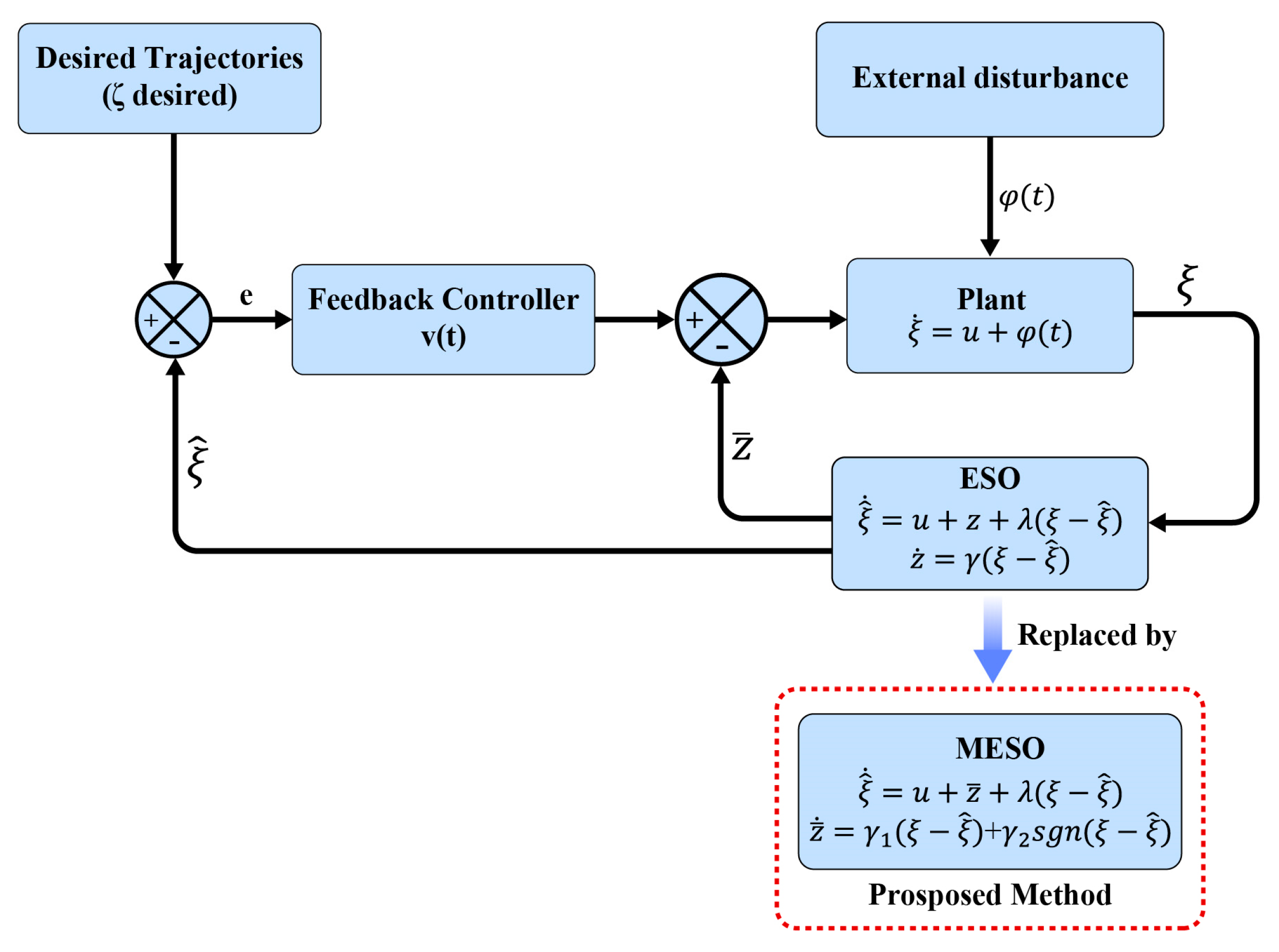
Adaptive super-twisting control (ASTC) is an advanced sliding mode control (SMC) technique that improves upon the standard super-twisting control (STC). This advanced method incorporates adaptive mechanisms designed to enhance robustness, reduce chattering, and dynamically adjust control parameters in reaction to system uncertainties and external disturbances. ASTC is particularly effective in managing systems marked by unknown or time-varying parameters.
In comparison to traditional super-twisting control (STC), ASTC is capable of handling higher levels of uncertainties and disturbances owing to its adaptive gain adjustment feature. This adaptability results in smoother control signals and significantly mitigates the occurrence of chattering, a common challenge in conventional sliding mode controllers. ASTC modifies the control gains k1 and k2 in real time, aligned with the system’s immediate behavior, thereby improving the controller’s response to fluctuating operational conditions. Similarly to STC, ASTC ensures finite-time convergence of the system states to the sliding manifold, maintaining performance integrity even amidst disturbances.
ASTC introduces an adaptive mechanism, evolved from STC, which enables the dynamic adjustment of the control parameters k 1 and k 2 , as specified in Equation (11). This adjustment occurs in response to detected system uncertainties and disturbances. By tuning the control gains in real time, ASTC more effectively minimizes sliding mode chattering and enhances overall robustness. The gains k 1 and k 2 are updated continuously through adaptive laws, typically expressed as k 1 = 1.5 M and k 2 = 1.1 M .

4. Observer Design

4.1. Extended State Observer

A salient characteristic of the Extended State Observer (ESO) lies in its minimal reliance on the dynamic information of the system. The design principally addresses the system’s relative order, encapsulating the core principles of Active Disturbance Rejection Control (ADRC). ADRC is renowned for its ability to estimate composite disturbances, including both external disturbances and uncertainties inherent to the system, which has propelled its popularity as a control strategy. The approach of ADRC is straightforward yet sophisticated, proving effective in a wide array of applications. Furthermore, ADRC facilitates feedback-based disturbance compensation, disturbance estimation, and model simplification. The methodology involves estimating disturbances through the ESO and mitigating them via appropriate feedback control mechanisms. This introduces an innovative paradigm for the estimation and suppression of disturbances and uncertainties, marking a departure from conventional methodologies by proactively addressing both internal and external disturbances. As a result, ADRC has catalyzed a series of pioneering solutions in tackling diverse industrial benchmark challenges.
In the classical ADRC framework, the trajectory of estimation error dynamics trends towards zero uniformly in the absence of disturbances. However, in the presence of disturbances, these trajectories do not reach zero but stabilize around the origin. This variance complicates the precise estimation of state trajectories and disturbance identification, making it more challenging to analyze state dynamics and develop control laws for system stability.
Consider the scenario of a first-order dynamic system subjected to unknown bounded disturbances, as described by the following differential equation:
ζ ˙ = u + φ t    
where φ t R represents the unknown bounded disturbance, u R denotes the control input, and the system state is denoted as ζ R .
Assumption 1. 
The system’s unknown bounded disturbance  φ t  adheres to the Lipschitz condition and remains globally bounded., i.e.,  φ t φ 0 . For all  t 0 ,  φ t  is continuously differentiable, and  φ ˙ t φ 0  and  φ ¨ t φ ̿ 0  for all  t 0 . Furthermore, the exact information about  φ t ,  φ ˙ t , and  φ ¨ t  is unknown, but they are, respectively, bounded by the known constants  φ 0 ,  φ ¯ 0 , and  φ ̿ 0 .
The primary concept behind employing ADRC techniques is the estimation of unknown bounded disturbances with adverse effects on the system’s characteristics. This is achieved by designing an appropriate observer, typically referred to as an ESO, and formulating suitable feedback control laws based on their estimated values to counteract these disturbances.
The dynamics of the classical ESO are as follows:
ζ ^ ˙ = u + z + λ ζ ζ ^ z ˙ = γ ζ ζ ^
Thus, the disturbance estimation error z is an auxiliary variable defined as z = φ t φ ^ , which provides information about the estimated disturbance. This variable is computed by considering the stability of the disturbance estimation error. The output estimation error q is defined as q = ζ ζ ^ . γ > 0 indicates a constant parameter, and λ > 0 is an adjustable observer gain.
The injection dynamics of the estimation error are formulated into
q ¨ + λ q ˙ + γ q = φ ˙ t
where q ˙ = φ t z λ q and z ˙ = γ q . To analyze the stability of Equation (23), introduce the following Lyapunov function in the q , φ domain:
V q , φ ^ = q 2 2 + φ ^ 2 2 γ
Based on Assumption 1, the time derivative of the Lyapunov function V q , φ ^ is expressed as follows:
V ˙ λ q 2 + φ t z φ 0 γ = λ q 2 + φ ^ φ 0 γ
Suppose φ ^ < α 1 , where α 1 > 0 is a scalar.
V ˙ remains strictly negative outside the set S = { q , φ ^ q 2 = α 1 φ 0 γ λ , φ ^ | α 1 } , while the Lyapunov function does not exhibit negative definiteness in the set S , i.e., V ˙ could be positive inside S . For any positive given constants α 1 , α 2 , there exist δ > 0 and t k such that for any t > t k , the trajectory of the disturbance error dynamics system satisfies the following:
q ¨ + 2 ζ ω n δ q ˙ + ω n 2 δ 2 q = φ ˙ t  
We assume λ = 2 ζ ω n δ and γ = ω n 2 δ 2 .
The conditions q t < α 2 and φ ^ t = φ t z t < α 1 hold for t > t δ , provided δ < 2 α 2 2 ζ ω n 3 α 1 φ ¯ 0 3 . Here, ζ represents the damping ratio, while ω n denotes the natural frequency.
When evaluating the stability of the error dynamics (Equation (25)), it is evident that in an undisturbed system, the undisturbed dynamics of the estimation error exhibit global exponential stability, as indicated by V ˙ λ q 2 . In contrast, in the presence of unknown bounded disturbances, the error dynamics trajectory does not converge to zero but remains confined within the scalar term | φ ^ φ 0 γ | , i.e., q t < α 2 . Thus, the disturbance estimation error also does not approach zero, represented as φ ^ t = φ t z t < α 1 .
The formula T e = T l + J d d t ω + B ω is transformed into
d d t ω = T e T l B ω m / J = T e J B J ω 1 J T L
In PMSMs, the torque is primarily generated by the q-axis current component. Maximizing the torque/current ratio, thus optimizing efficiency, is achievable when i d = 0 , which also reduces the total stator current, thereby minimizing copper losses in the motor windings. Additionally, it helps protect the permanent magnets from unnecessary demagnetizing fields, thus maintaining their performance and lifespan.
Controlling i d = 0 , the electromagnetic torque equation T e = 3 2 p i q i d L d L q + ψ f can be rewritten as T e = 3 2 p i q ψ f .
Let K t = 3 / 2 p ψ f ; then, T e = 3 / 2 p ψ f i q = K t i q , and substituting this into (27) yields
d d t ω = K t J i q B J ω 1 J T L  
Let u = K t J B J ω and φ ( t ) = 1 J T L .
Design the observer as follows:
d ω ^ d t = u + z + λ ( ω ω ^ ) z ˙ = γ 1 ( ω ω ^ )
Over time, z φ ( t ) and T L = J z .

4.2. Modified Extended State Observer

To address the challenge of accurately estimating unknown bounded disturbances, a novel disturbance observer has been designed. Figure 1 illustrates the block diagram of the proposed ASTC-based MESO scheme for a plant system.
For the system defined by Equation (21), the dynamics of the proposed improved ESO are expressed as follows:
ζ ^ ˙ = u + z + λ ζ ζ ^ z ˙ = γ 1 ζ ζ ^ + γ 2 s g n ζ ζ ^
In this paper, the function s g n t is defined by
s g n t = + 1 , t > 0 0 , t = 0 1 , t < 0
Here, γ 1 and γ 2 represent the adjustable parameters of the observer, and z denotes the new disturbance dynamics, providing an estimation of the disturbance information.
q ¨ + λ q ˙ + γ 1 q = φ ˙ t γ 2 s g n q  
Consider the disturbance system expressed using the dynamic expression of estimation errors:
q ¨ t + λ q ˙ t + γ 1 q t = K t s g n q t
where K t = γ 2 φ ˙ t s g n q t and s g n q t 0 . If the adjustable gains satisfy λ > 0 , γ 1 > 0 , and γ 2 > 0 , let γ 1 < λ 2 4 hold true. Under these conditions, the roots of the characteristic equation s 2 + λ s + γ 1 = 0 are real, distinct, and negative.

4.3. MESO Stability Analysis

Case 1: When q t > 0 , with s g n q t = 1 , Equation (32) can be rewritten as follows:
q ¨ t + λ q ˙ t + γ 1 q t = K t
Define a function f t as follows:
f t = q ˙ t + r q t + K t μ s g n q t
where μ > 0 and r > 0 are real constants satisfying μ + r = λ and μ r = γ 1 .
Given q t > 0 , from q ¨ t + λ q ˙ t + γ 1 q t + K t = 0 , we derive the following:
d f t d t + μ f t = K ˙ t μ  
Knowing K t = γ 2 φ ˙ t and based on Assumption 1 that φ ¨ t φ ̿ 0 , we obtain K ˙ t φ ̿ 0 . By substituting the upper bound of K ˙ t into ( 35 ) , it can be rewritten as
d f t d t + μ f t φ ̿ 0 μ
Therefore, it can be obtained that f t F 1 + F 2 e μ t , where F 1 = φ ̿ 0 μ 2 and F 2 = f 0 φ ̿ 0 μ 2 , and F 1 > 0 and F 2 > 0 are positive constants. Thus, for all t 0 , there is f t F 1 + F 2 e μ t .
Thus, it is derived that f t F 1 + F 2 e μ t , where F 1 = φ ̿ 0 μ 2 and F 2 = f 0 φ ̿ 0 μ 2 , with both F 1 and F 2 being positive constants. Hence, for all t 0 , f t F 1 + F 2 e μ t .
For stability analysis, let the Lyapunov function be
V q = 1 2 q 2 t
Its time derivative is as follows:
V ˙ q = q t f t r q t K t μ s g n q t q t F 1 + F 2 e μ t q t γ 2 φ 0 μ r q 2 t
Since μ > 0 , for a sufficiently large gain γ 2 , the condition F 1 + F 2 e μ t < γ 2 φ 0 μ ρ , where ρ > 0 , holds. Therefore, V ˙ ρ q t r q 2 t < 0 for q t > 0 , indicating that q t approaches zero progressively. Once the error q t = 0, the system dynamics switch to Case 3.
Case 2: When q t < 0 , with s g n q t = 1 , Equation (32) can be rewritten as follows:
  q ¨ t + λ q ˙ t + γ 1 q t = K t  
Since q t < 0 , from q ¨ t + λ q ˙ t + γ 1 q t K t = 0 , we derive the following:
d f t d t + μ f t = K ˙ t μ
Knowing K t = γ 2 + φ ˙ t , and based on Assumption 1, φ ¨ t φ ̿ 0 , we have K ˙ t φ ̿ 0 . Substituting the upper bound of K ˙ t into (35), the equation below is formulated:
d f t d t + μ f t = φ ̿ 0 μ
Thus, it results that f t F 1 + F 2 e μ t , where F 1 and F 2 are constants.
To analyze stability, define the Lyapunov function as V q = 1 2 q 2 t .
Its time derivative is as follows:
V ˙ q = q t f t r q t K t μ s g n q t q t F 1 + F 2 e μ t q t γ 2 + φ 0 μ r q 2 t
Because μ > 0 , for a sufficiently large gain γ 2 , the condition F 1 + F 2 e μ t < γ 2 + φ 0 μ ρ is satisfied, where ρ > 0 . Therefore, for q t < 0 , V ˙ ρ q t r q 2 t 0 . As revealed by the above analysis, q t will approach zero progressively. Once the error reaches 0, the system dynamics transition to Case 3.
Case 3: When q t = 0 , the signum function s g n q t = 0 . Considering this, Equation (31) can be reformulated as follows:
q ¨ t + λ q ˙ t + γ 1 q t = φ ˙ t
For the undisturbed system,
q ¨ t + λ q ˙ t + γ 1 q t = 0
Redefine the function f t as specified in Equation (12):
f t = q ˙ t + r q t
where r > 0 . Given that the roots of Equation (44) are stable, we derive the following differential equation:
d f t d t + μ f t = 0  
Thus, it can be deduced that f t = f 0 e μ t . Consequently, the upper bound of f t is f t F 0 e μ t , where F 0 > 0 is a constant parameter.
For stability analysis, define the Lyapunov function as follows:
V q , q ˙ = 1 2 q 2 t + 1 2 q ˙ 2 t
with its time derivative expressed as
V ˙ q , q ˙ = q t q ˙ t + q ˙ t q ¨ t λ f 2 t λ F 0 2 e 2 μ t
Since μ > 0 and λ > 0 , V ˙ 0 . Thus, this indicates that both q ˙ t and q t approach zero.
For the disturbed system,
q ¨ t + λ q ˙ t + γ 1 q t = φ ˙ t
Here, the disturbance terms introduce unknown bounded disturbances with positive or negative amplitudes into the overall system dynamics. Therefore, the stability analysis of the disturbed system requires determining when to switch to Case 1 or Case 2, depending on the magnitude of the disturbances. In Case 1, characterized by positive amplitude unknown bounded disturbances, and Case 2, marked by negative amplitude disturbances, the system’s stability analysis has been discussed, and asymptotic convergence to zero has been achieved.
However, for disturbances like a sinusoidal function, whose amplitude becomes zero only at the zero crossings (transitioning from positive to negative or vice versa), the system behaves momentarily like an undisturbed system, i.e., φ ˙ t = 0 , and gradually approaches the origin.
Thus, based on the stability analysis of the aforementioned cases, it can be concluded that V ˙ 0 , implying that the error and its rate of change, namely q t and q ˙ t , approach zero progressively. In the presence of unknown bounded disturbances, the dynamics of the estimation error also approach zero progressively. Thus, the disturbance dynamic variable z ¯ effectively monitors, so that the time-varying and bounded disturbances affecting the system can be explained. The disturbance observer represents an MESO.
Let u = K t J B J ω , φ ( t ) = 1 J T L ; then, the observer is designed as follows:
d ω ^ d t = u + z + λ ( ω ω ^ ) z ˙ = γ 1 ( ω ω ^ ) + γ 2 s i g n ( ω ω ^ )
Over time, z φ ( t ) and T L = J z

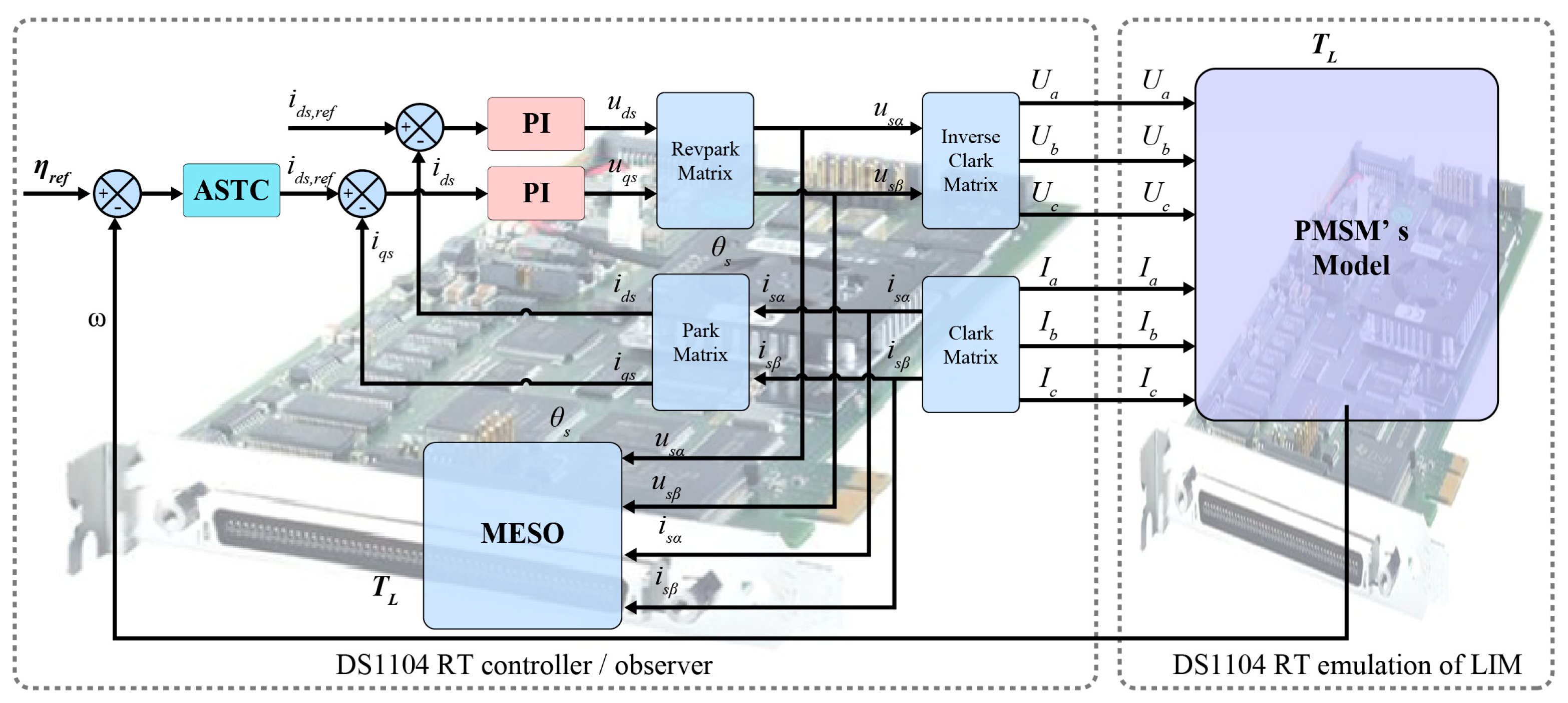
5. Hardware-in-the Loop (HIL) Validation

5.1. HIL Experiment Test

A vector control system for a surface-mounted PMSM was tested in a hardware-in-the-loop test platform to evaluate the performance of the proposed technique. The complete architecture of the HIL test system is presented in Figure 2. It mainly consists of two DS1104 real-time (RT) board cards: one for the LIM controller/observer application, and another for the emulation of LIM. The implementation of the HIL system is in real time, using a sampling frequency of 10 kHz. To enhance the speed loop’s response time, an ASTC utilizing a MESO based on an ESO was implemented. The block diagram of the ASTC integrated with MESO for the PMSM is shown in the figure.
The experimental setup utilizes a surface-mounted PMSM, with its detailed parameters listed in Table 1.

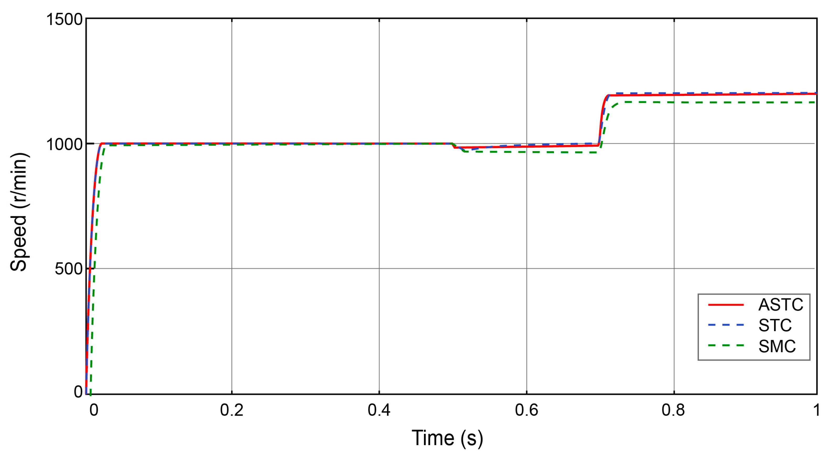
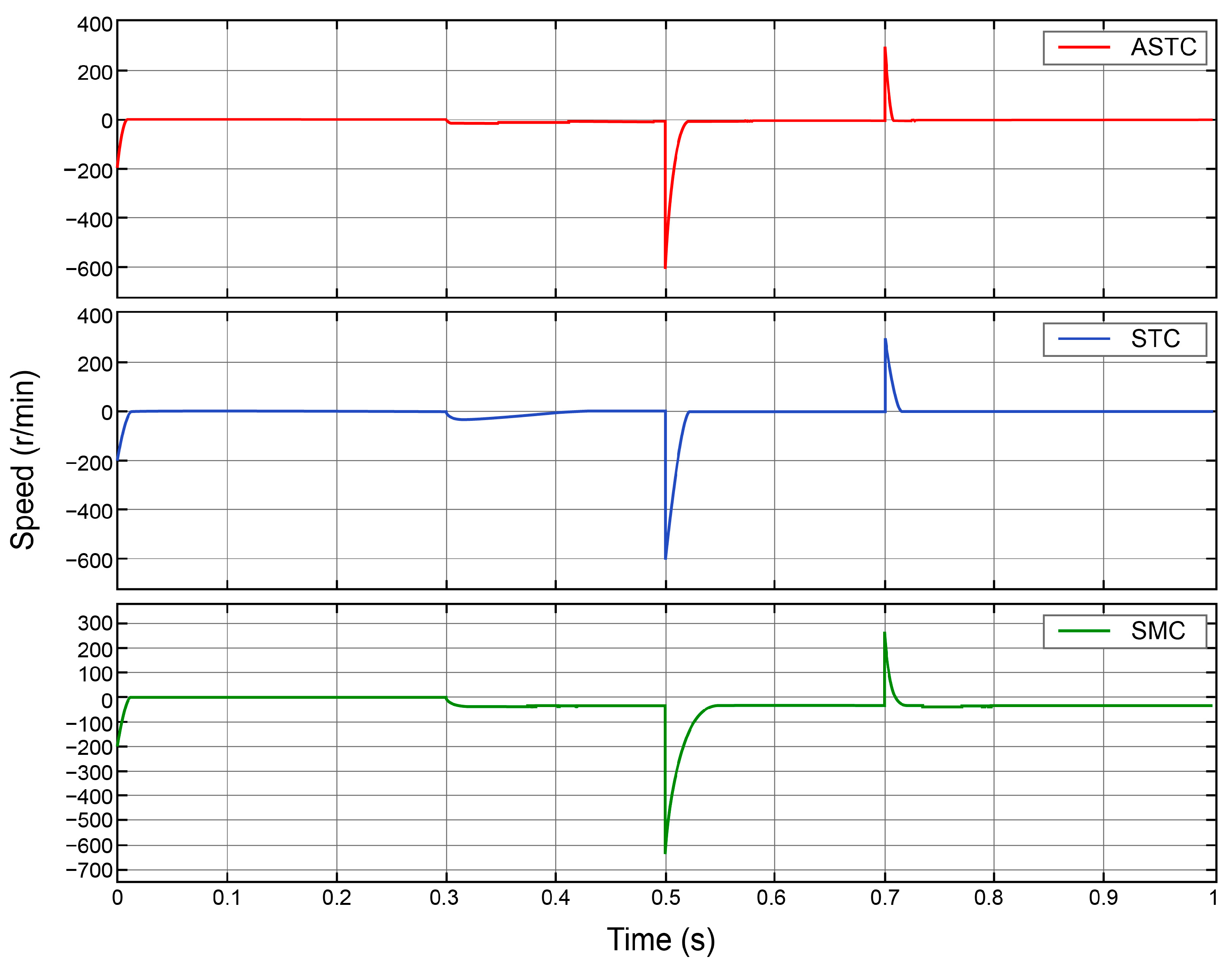
5.2. Control Performance Analysis

The parameters of the ASTC were selected through a combination of Lyapunov stability analysis and frequency-domain bandwidth tuning to achieve a balance between dynamic performance and steady-state precision. The adaptive gain parameters for the ASTC were optimized using an error-driven adaptation law, where the gains scale with the rotor speed tracking error. This ensures finite-time convergence and effectively suppresses chattering. The adaptation mechanism enhances the system’s transient response and reduces overshoot by dynamically adjusting the control authority based on real-time disturbances. For the ASTC, the parameters were set with M = 13. For purposes of comparative analysis, a standard STC and SMC were also configured, with parameters k1 = 5, k2 = 200, and ε = 20 .
We conducted a speed tracking experiment, which involved maintaining a constant speed followed by a transition to variable-speed conditions in the PMSM. This experiment aimed to verify the proposed control strategy’s effectiveness in speed regulation and its capability to suppress oscillations. The simulation parameters were set as follows: a duration of 1 s and a sampling time of 1 × 10⁻⁶ s. In Case 1, the system’s target speed was established at 1000 rpm, starting without load. At 0.5 s, a sudden torque of 20 N·m was applied, and at 0.7 s, the speed was abruptly changed to 1200 rpm. Figure 3 illustrates the speed response under different control methods.
Further comparative analysis between the proposed strategy and traditional sliding mode was performed by focusing on the start-up phase, load increase phase, and speed increase phase.
Compared to traditional STC and SMC, the designed control method significantly enhances system response speed while maintaining output precision. It enables rapid convergence, even under sudden acceleration, displaying superior speed regulation performance and improving the dynamic quality and disturbance rejection capability of the PMSM speed control system. By implementing ASTC, the system’s disturbance rejection capability is substantially enhanced. The proposed strategy, in comparison with traditional STC and SMC, adjusts itself in the face of disturbances, avoiding significant fluctuations and loss of control, with minimal disturbance impact. The oscillations typical of sliding mode approaches, generally indicated as tracking errors in system speed, are shown in Figure 4. Despite external load torque disturbances and parameter uncertainties, the speed tracking error exhibits rapid convergence, effectively mitigating the oscillations.
In Case 2, the system’s target speed was initially set at 200 rpm, with no load at 0 s. At 0.3 s, a sudden torque of 20 N·m was applied while maintaining the speed at 200 rpm. At 0.5 s, the speed increased to 800 rpm. Finally, at 0.7 s, the speed decreased to 500 rpm. Figure 5 illustrates the speed response under different control methods for this scenario. Figure 5 illustrates the speed response under different control methods in Case 2, the ASTC demonstrates superior response performance in both acceleration and deceleration scenarios. Similarly, Tracking errors have the same case from Figure 6.
Several cases were compared in order to assess the impact of the ASTC compared to the traditional STC. By analyzing these different scenarios, we can gain a deeper understanding of how the ASTC method enhances performance, particularly in terms of responsiveness, stability, and efficiency. This comparative study will provide a more comprehensive evaluation of the performance improvements achieved with ASTC, highlighting its advantages in handling varying load conditions, speed transitions, and torque fluctuations. Through this analysis, the potential benefits of adopting ASTC over STC in real-world applications can be clearly demonstrated.
In Figure 7, it is evident that the primary voltage and current responses remain within reasonable bounds, even under external load torque disturbances, demonstrating satisfactory performance.
The control results validate the effectiveness of the proposed ASTC strategy in enhancing the speed regulation performance of the PMSM. ASTC demonstrates superior disturbance rejection, reduced oscillations, and faster convergence compared to traditional SMC and STC methods. The system exhibits remarkable robustness against external torque disturbances and parameter uncertainties, ensuring stable speed tracking even under dynamic conditions such as load changes and speed transitions. This comparative analysis highlights the potential of ASTC to improve responsiveness, stability, and efficiency in PMSM applications, offering significant advantages for real-world industrial implementations where rapid speed adjustments and load fluctuations are common. Additionally, the voltage and current responses remain within acceptable limits, further reinforcing the practicality and robustness of the proposed control strategy in demanding operating conditions.

5.3. Observer Performance Analysis

In this section, simulations of the load torque ESO and MESO are carried out for verifying the performance of the observer. The MESO’s observer bandwidth and disturbance compensation gain were calibrated via pole placement to achieve a trade-off between rapid disturbance estimation and noise amplification. A higher observer bandwidth improves disturbance rejection but risks amplifying high-frequency sensor noise. The observer gain, λ = 40 , and observer parameters, γ 1 = 300 ,   γ 2 = 100 , were set. A step load of 20 N·m was applied at 0.5 s during a no-load start condition.All initial conditions for the load torque observer were set to zero.
Figure 8 reports the estimated values of the load torque TL: an exponential convergence in the load torque estimation was achieved.
Figure 9 displays the corresponding estimation errors for the rotor torque TL, showing that exponential convergence was also achieved in the estimation, with the error rapidly converging toward zero.
The HIL experiments of the MESO effectively demonstrate the performance and accuracy of the proposed observer in estimating load torque. By calibrating the observer bandwidth and disturbance compensation gain through pole placement, a balanced trade-off was achieved between rapid disturbance estimation and minimizing high-frequency sensor noise amplification. The results show that the load torque estimation converges exponentially, with the estimation error rapidly decreasing toward zero, indicating the observer’s efficiency in accurately tracking torque disturbances. These findings underscore the effectiveness of the MESO in real-time disturbance compensation, providing a robust and reliable method for load torque estimation in dynamic operating conditions.

6. Conclusions

This study introduces an innovative sliding mode control (SMC) strategy based on an Adaptive Super-Twisting Controller (ASTC) for permanent magnet synchronous motor (PMSM) speed regulation. The proposed framework effectively addresses the limitations of conventional Proportional–Integral (PI) control and first-order sliding mode approaches, particularly improving robustness and mitigating chattering phenomena while ensuring high-precision control performance. The key contributions and findings are summarized as follows:
  • The ASTC ensures efficient PMSM operation in a wide range of operating conditions, effectively handling disturbances and uncertainties such as parameter variations, load disturbances, and voltage fluctuations. By dynamically adjusting the sliding mode control law and optimizing control parameters, the ASTC enables rapid, accurate regulation of motor states while minimizing chattering and reducing energy consumption, thereby enhancing precision and efficiency in real-time control.
  • The ASTC demonstrates exceptional robustness and adaptability, ensuring stable performance even under significant disturbances. The strategy maintains high control precision even with changing motor parameters, highlighting its significant potential for industrial applications that require real-time, reliable performance.
  • While the ASTC successfully improves system robustness, challenges remain in optimizing the transient response to abrupt load changes. Future work will focus on refining this aspect by developing a multi-rate tuning strategy to balance fast convergence with effective suppression of overshoot, improving overall system stability.
  • The MESO effectively compensates for matched disturbances but remains dependent on accurate motor parameter identification. Under extreme operating conditions where parameter values are difficult to obtain or fluctuate, the MESO’s performance may be impacted. This limitation is particularly relevant in systems where precise parameter values are hard to determine.
Future research will focus on integrating online parameter estimation techniques. This would reduce sensitivity to variations in motor inductance and resistance, thus further enhancing the controller’s robustness and broadening its applicability in real-world electromechanical systems. Further improvements will aim to refine the transient response and extend the operational range of the controller, making it more versatile for industrial applications.

Author Contributions

Conceptualization, L.P.; methodology, L.P.; software, B.C.; validation, C.F.; formal analysis, B.C.; resources, L.P.; data curation, C.F.; writing—original draft preparation, L.P.; writing—review and editing, B.C.; visualization, B.C.; supervision, L.P.; project administration, B.C.; All authors have read and agreed to the published version of the manuscript.

Funding

This research was funded by the Natural Science Foundation of Chongqing Municipality under Grant CSTB2023NSCQ-LZX0169.

Data Availability Statement

Data are contained within the article.

Conflicts of Interest

Authors Lili Pan and Bin Chen were employed by the company China Merchants Testing Vehicle Technology Research Institute. The remaining authors declare that the research was conducted in the absence of any commercial or financial relationships that could be construed as a potential conflict of interest.

References

  1. Brown, T.; Davis, K. Industrial applications of permanent magnet synchronous motors: A review. IEEE Trans. Ind. Appl. 2022, 58, 2345–2356. [Google Scholar]
  2. Zhang, X.; Li, Y. Advanced control strategies for permanent magnet synchronous motors: A review. IEEE Trans. Ind. Electron. 2023, 70, 4123–4135. [Google Scholar]
  3. Sun, X.; Wu, M.; Lei, G.; Guo, Y.; Zhu, J. An Improved Model Predictive Current Control for PMSM Drives Based on Current Track Circle. IEEE Trans. Ind. Electron. 2020, 68, 3782–3793. [Google Scholar] [CrossRef]
  4. Mu, X.; Zeng, F.; Cui, Y.; Song, S.; Yao, Y. A Deadbeat Predictive Current Control Method of PMSM Based on Double Disturbance Observer. Lect. Notes Electr. Eng. 2022, 644, 2541–2548. [Google Scholar]
  5. Carlet, P.; Favato, A.; Bolognani, S.; Dorfler, F. Data-Driven Continuous-Set Predictive Current Control for Synchronous Motor Drives. IEEE Trans. Power Electron. 2022, 37, 6637–6646. [Google Scholar] [CrossRef]
  6. Li, J.; Liu, B.; Li, S.; Yu, B.; Feng, J.; Song, W. Dead-beat Predictive Control of Permanent Magnet Synchronous Motors with Improved Dead-time Compensation. In Proceedings of the 2021 IEEE International Conference on Predictive Control of Electrical Drives and Power Electronics (PRECEDE), Jinan, China, 20–22 November 2021; pp. 336–340. [Google Scholar]
  7. Luo, G.; Zhang, R.; Chen, Z.; Tu, W.; Zhang, S.; Kennel, R. A Novel Nonlinear Modeling Method for Permanent-Magnet Synchronous Motors. IEEE Trans. Ind. Electron. 2016, 63, 6490–6498. [Google Scholar] [CrossRef]
  8. Jung, S.Y.; Hong, J.; Nam, K. Current minimizing torque control of the IPMSM using Ferrari’s method. IEEE Trans. Power Electron. 2013, 28, 5603–5617. [Google Scholar] [CrossRef]
  9. Li, S.; Han, D.; Sarlioglu, B. Modeling of Interior Permanent Magnet Machine Considering Saturation, Cross Coupling, Spatial Harmonics, and Temperature Effects. IEEE Trans. Transp. Electrif. 2017, 3, 682–693. [Google Scholar] [CrossRef]
  10. Drobnič, K.; Gašparin, L.; Fišer, R. Fast and accurate model of interior permanent-magnet machine for dynamic characterization. Energies 2019, 12, 783. [Google Scholar] [CrossRef]
  11. Zhang, Q.; Guo, H.; Guo, C.; Liu, Y.; Wang, D.; Lu, K.; Chen, D. An adaptive proportional-integral-resonant controller for speed ripple suppression of PMSM drive due to current measurement error. Int. J. Electr. Power Energy Syst. 2021, 129, 106866. [Google Scholar] [CrossRef]
  12. Sarathkumar, D.; Raj, R.A.; Sidthik Akbar, S.; Rajesh Kanna, R.; Andrews, L.J.B.; Alagappan, A. IOT Based Motor Control and Line Detection for Smart Agriculture. In Proceedings of the 2024 IEEE International Students’ Conference on Electrical, Electronics and Computer Science, Bhopal, India, 24–25 February 2024; pp. 1–6. [Google Scholar]
  13. Geetha, E.; Nagarajan, C. Stochastic Rule Control Algorithm Based Enlistment of Induction Motor Parameters Monitoring in IoT Applications. Wirel. Pers. Commun. 2018, 102, 3629–3645. [Google Scholar]
  14. Vlachou, E.I.; Vlachou, V.I.; Efstathiou, D.E.; Karakatsanis, T.S. Overview of IoT Security Challenges and Sensors Specifications in PMSM for Elevator Applications. Machines 2024, 12, 839. [Google Scholar] [CrossRef]
  15. Attestog, S.; Senanayaka, J.S.L.; Van Khang, H.; Robbersmyr, K.G. Robust Active Learning Multiple Fault Diagnosis ofPMSM Drives With Sensorless Control Under Dynamic Operations and Imbalanced Datasets. IEEE Trans. Ind. Inform. 2023, 19, 9291–9301. [Google Scholar]
  16. Riaz, S.; Qi, R.; Tutsoy, O.; Iqbal, J. A novel adaptive PD-type iterative learning control of the PMSM servo system with the friction uncertainty in low speeds. PLoS ONE 2023, 18, e0279253. [Google Scholar] [CrossRef] [PubMed]
  17. Li, W.; Xu, Z.; Zhang, Y. Induction motor control system based on FOC algorithm. In Proceedings of the 2019 IEEE 8th Joint International Information Technology and Artificial Intelligence Conference (ITAIC), Chongqing, China, 24–26 May 2019; pp. 1544–1548. [Google Scholar]
  18. Abirami, M.; Balakrishnan, P. DTC-FOC Hybrid Controller to Control the Speed and Torque of BLDC Motor. In Proceedings of the 2023 Innovations in Power and Advanced Computing Technologies (i-PACT), Kuala Lumpur, Malaysia, 8–10 December 2023; pp. 1–6. [Google Scholar]
  19. Huang, Y.; Gao, X.; Song, Z.; Liu, X.; Liu, C. A Novel Wireless Motor Based on Three-Phase Six-Stator-Winding PMSM. IEEE Trans. Ind. Electron. 2024, 71, 7590–7598. [Google Scholar]
  20. Liu, Z.; Zhao, Y.; Zhang, O.; Chen, W.; Wang, J.; Gao, Y.; Liu, J. A Novel Faster Fixed-Time Adaptive Control for Robotic Systems With Input Saturation. IEEE Trans. Ind. Electron. 2023, 71, 5215–5223. [Google Scholar]
  21. Romanov, A.M.; Slaschev, B.V.; Volkova, M.A. A comparison of hardware implementations of FOC controllers for asynchronous motor drive based on FPGA. In Proceedings of the 2016 2nd International Conference on Industrial Engineering, Applications and Manufacturing (ICIEAM), Chelyabinsk, Russia, 19–20 May 2016; pp. 1–5. [Google Scholar]
  22. Guo, X.; Wang, W.; Song, S. Design of Permanent Magnet Submersible Motor Driving System Based on FOC Algorithm. In Proceedings of the 2023 26th International Conference on Electrical Machines and Systems (ICEMS), Zhuhai, China, 5–8 November 2023; pp. 4943–4946. [Google Scholar]
  23. Çavuş, B.; Aktaş, M. MPC-Based Flux Weakening Control for Induction Motor Drive With DTC for Electric Vehicles. IEEE Trans. Power Electron. 2023, 38, 4430–4439. [Google Scholar]
  24. Payami, S.; Behera, R.K.; Iqbal, A. DTC of Three-Level NPC Inverter Fed Five-Phase Induction Motor Drive With Novel Neutral Point Voltage Balancing Scheme. IEEE Trans. Power Electron. 2018, 33, 1487–1500. [Google Scholar] [CrossRef]
  25. Holakooie, M.H.; Ojaghi, M.; Taheri, A. Modified DTC of a Six-Phase Induction Motor With a Second-Order Sliding-Mode MRAS-Based Speed Estimator. IEEE Trans. Power Electron. 2019, 34, 600–611. [Google Scholar]
  26. Niu, F.; Huang, X.; Ge, L.; Zhang, J.; Wu, L.; Wang, Y.; Li, K.; Fang, Y. A Simple and Practical Duty Cycle Modulated Direct Torque Control for Permanent Magnet Synchronous Motors. IEEE Trans. Power Electron. 2019, 34, 1572–1579. [Google Scholar]
  27. Shinohara, A.; Inoue, Y.; Morimoto, S.; Sanada, M. Direct Calculation Method of Reference Flux Linkage for Maximum Torque per Ampere Control in DTC-Based IPMSM Drives. IEEE Trans. Power Electron. 2017, 32, 2114–2122. [Google Scholar] [CrossRef]
  28. Yin, Y.; Liu, L.; Vazquez, S.; Xu, R.; Dong, Z.; Liu, J. Disturbance and Uncertainty Attenuation for Speed Regulation of PMSM Servo System Using Adaptive Optimal Control Strategy. IEEE Trans. Transp. Electrif. 2023, 9, 3410–3420. [Google Scholar]
  29. Zhang, K.; Wang, L.; Fang, X. Adaptive Nonlinear Speed Tracking Control of Permanent Magnet Linear Synchronous Motor Based on I&I Theory. IEEE Trans. Ind. Appl. 2024, 60, 7835–7843. [Google Scholar]
  30. Lin, X.; Wu, C.; Yao, W.; Liu, Z.; Shen, X.; Xu, R.; Sun, G.; Liu, J. Observer-Based Fixed-Time Control for Permanent-Magnet Synchronous Motors With Parameter Uncertainties. IEEE Trans. Power Electron. 2023, 38, 4335–4344. [Google Scholar]
  31. Wang, Y.; Zhou, M.; Hou, D.; Cao, W.; Huang, X. Composite Data Driven-Based Adaptive Control for a Piezoelectric Linear Motor. IEEE Trans. Instrum. Meas. 2022, 71, 1–12. [Google Scholar]
  32. Wang, X.; Wang, W.; Li, L.; Shi, J.; Xie, B. Adaptive Control of DC Motor Servo System With Application to Vehicle Active Steering. IEEE/ASME Trans. Mechatron. 2019, 24, 1054–1063. [Google Scholar]
  33. Li, Y.; Liu, D.; Wu, T.; Guo, W.; Zhang, X.; Deng, Y. Model Predictive Current Control for Permanent Magnet Synchronous Motor based on Neural Network. In Proceedings of the 2023 IEEE International Conference on Predictive Control of Electrical Drives and Power Electronics (PRECEDE), Wuhan, China, 16–19 June 2023; pp. 1–6. [Google Scholar]
  34. Li, Y.; Zhang, P.; Hang, J.; Ding, S.; Liu, L.; Wang, Q. Comparison of dynamic characteristics of field oriented control and model predictive control for permanent magnet synchronous motor. In Proceedings of the 2018 13th IEEE Conference on Industrial Electronics and Applications (ICIEA), Wuhan, China, 31 May–2 June 2018; pp. 2431–2434. [Google Scholar]
  35. Lin, R.; Huang, S.; Cao, G.; Wu, C. Model-Predictive-Control-Based Speed Control Strategies of Permanent Magnet Synchronous Motors. In Proceedings of the 2023 IEEE International Conference on Predictive Control of Electrical Drives and Power Electronics (PRECEDE), Wuhan, China, 16–19 June 2023; pp. 1–7. [Google Scholar]
  36. Li, Y.; Miao, Z.; Zhang, L.; Zhang, H. Application of Finite Set Model Predictive Control to Five-Phase Induction Motors. In Proceedings of the 2023 5th International Conference on Electrical Engineering and Control Technologies (CEECT), Chengdu, China, 15–17 December 2023; pp. 469–473. [Google Scholar]
  37. Santos, T.B.D.; Oliani, I.; Figueiredo, R.; Albieiro, D.; Pelizari, A.; Sguarezi Filho, A.J. Robust Finite Control Set Model Predictive Current Control for Induction Motor Using Deadbeat Approach in Stationary Frame. IEEE Access 2023, 11, 13067–13078. [Google Scholar]
  38. Zhou, Z.; Wang, J.; Zhang, S. Speed Synchronization Control Strategy of Dual-Motor System With Explicit Model Predictive Control. IEEE J. Emerg. Sel. Top. Power Electron. 2024, 12, 2787–2798. [Google Scholar] [CrossRef]
  39. Kim, S.H.; Kim, K.K.K. Model Predictive Control for Energy-Efficient Yaw-Stabilizing Torque Vectoring in Electric Vehicles With Four In-Wheel Motors. IEEE Access 2023, 11, 37665–37680. [Google Scholar] [CrossRef]
  40. Hou, P.; Wang, X.; Sheng, Y. Research on Flux-Weakening Control System of Interior Permanent Magnet Synchronous Motor Based on Fuzzy Sliding Mode Control. In Proceedings of the 2019 Chinese Control And Decision Conference (CCDC), Nanchang, China, 3–5 June 2019; pp. 3151–3156. [Google Scholar]
  41. Jia, L.; Huang, Y.; Zheng, J.; Chen, J.; Tao, Y.; Li, P. Fuzzy Sliding Mode Control of Permanent Magnet Synchronous Motor Based on the Integral Sliding Mode Surface. In Proceedings of the 2019 22nd International Conference on Electrical Machines and Systems (ICEMS), Harbin, China, 11–14 August 2019; pp. 1–6. [Google Scholar]
  42. Zhu, C.; Tu, Q.; Jiang, C.; Pan, M.; Huang, H. A Cross Coupling Control Strategy for Dual-Motor Speed Synchronous System Based on Second Order Global Fast Terminal Sliding Mode Control. IEEE Access 2020, 8, 217967–217976. [Google Scholar]
  43. Liu, Z.; Lin, X.; Gao, Y.; Xu, R.; Wang, J.; Wang, Y.; Liu, J. Fixed-Time Sliding Mode Control for DC/DC Buck Converters With Mismatched Uncertainties. IEEE Trans. Circuits Syst. I Regul. Pap. 2023, 70, 472–480. [Google Scholar] [CrossRef]
  44. Liu, Z.; Liu, J.; Zhang, O.; Zhao, Y.; Chen, W.; Gao, Y. Adaptive Disturbance Observer-Based Fixed-Time Tracking Control for Uncertain Robotic Systems. IEEE Trans. Ind. Electron. 2024, 71, 14823–14831. [Google Scholar]
  45. Zhao, K.; Yang, L.; Zhao, S.; Hu, H. A Hybrid Control Strategy for Sensorless PMSM with a Super-Twisting Sliding Mode Observer and a Two-stage Filter Based on Fuzzy Rules. In Proceedings of the IECON 2022–48th Annual Conference of the IEEE Industrial Electronics Society, Brussels, Belgium, 17–20 October 2022; pp. 1–7. [Google Scholar]
  46. Hou, Q.; Ding, S. Finite-Time Extended State Observer-Based Super-Twisting Sliding Mode Controller for PMSM Drives With Inertia Identification. IEEE Trans. Transp. Electrif. 2022, 8, 1918–1929. [Google Scholar] [CrossRef]
  47. Lin, C.; Sun, S.; Walker, P.; Zhang, N. Accelerated Adaptive Second Order Super-Twisting Sliding Mode Observer. IEEE Access 2019, 7, 25232–25238. [Google Scholar] [CrossRef]
  48. Gao, P.; Zhang, G.; Ouyang, H.; Mei, L. An Adaptive Super Twisting Nonlinear Fractional Order PID Sliding Mode Control of Permanent Magnet Synchronous Motor Speed Regulation System Based on Extended State Observer. IEEE Access 2020, 8, 53498–53510. [Google Scholar]
  49. Singh, S.; Goyal, J.K.; Sachan, A.; N, A.P.; Tiwari, A.K.; Kamal, S.; Ghosh, S.; Purwar, S.; Xiong, X. Modified ESO based disturbance rejection for dynamical systems: An experimental study. J. Process Control 2024, 141, 103263. [Google Scholar] [CrossRef]
  50. Edwards, C.; Shtessel, Y.B. Adaptive continuous higher order sliding mode control. Automatica 2016, 65, 183–190. [Google Scholar] [CrossRef]
  51. Smith, R.; Johnson, L. Challenges and opportunities in high-performance motor drives for electric vehicles. J. Power Electron. 2023, 18, 567–579. [Google Scholar]
  52. Wang, H.; Chen, Z. Adaptive super-twisting sliding mode control for nonlinear systems with uncertainties. Automatica 2022, 115, 108912. [Google Scholar]
  53. Liu, J.; Sun, M. Enhanced extended state observer design for disturbance estimation in motor drives. IEEE Trans. Power Electron. 2024, 39, 1234–1245. [Google Scholar]
  54. Obeid, H.; Laghrouche, S.; Fridman, L.; Chitour, Y.; Harmouche, M. Barrier Function-Based Adaptive Super-Twisting Controller. IEEE Trans. Autom. Control 2020, 65, 4928–4933. [Google Scholar] [CrossRef]
Figure 1. The overall structure of the proposed ASTC-based MESO scheme.
Actuators 14 00161 g001
Figure 2. The overall structure of the proposed ASTC-based MESO scheme for the PMSM system.
Actuators 14 00161 g002
Figure 3. Speed tracking performance in Case 1 between different control algorithms.
Actuators 14 00161 g003
Figure 4. Speed tracking error performance in Case 1 between different control algorithms.
Actuators 14 00161 g004
Figure 5. Speed tracking performance in Case 2 between different control algorithms.
Actuators 14 00161 g005
Figure 6. Speed tracking error performance in Case 2 between different control algorithms.
Actuators 14 00161 g006
Figure 7. One-phase primary voltage and current of proposed control scheme.
Actuators 14 00161 g007
Figure 8. Load torque TL estimated tracking performance with ESO and MESO.
Actuators 14 00161 g008
Figure 9. Load Torque TL estimated tracking error performance with ESO and MESO.
Actuators 14 00161 g009
Table 1. Surface-mounted PMSM parameters.
ParameterDefinitionValue
R s Stator phase resistance0.5 (Ω)
LsStator phase inductance0.0014 (H)
pNumber of pole pairs3 (pairs)
ψFlux linkage0.149 (Wb)
FrDamping coefficient0.0001 (N·m·s)
J Moment of inertia0.016 (kg·m2)
UDC bus voltage400 (V)
B Static friction coefficient0.0002024
Disclaimer/Publisher’s Note: The statements, opinions and data contained in all publications are solely those of the individual author(s) and contributor(s) and not of MDPI and/or the editor(s). MDPI and/or the editor(s) disclaim responsibility for any injury to people or property resulting from any ideas, methods, instructions or products referred to in the content.

