Article

Adaptive Output Regulation for PMSM Speed Servo System via Time-Varying Internal Model Approach

by
Hui Song
1,2,
Zhaowu Ping
1,2,*,
Jiaze Hui
2,
Yunzhi Huang
1 and
Jun-Guo Lu
3
1
School of Electrical Engineering and Automation, Hefei University of Technology, Hefei 230009, China
2
Jianghuai Advance Technology Center, Hefei 230088, China
3
Department of Automation, Shanghai Jiao Tong University, Shanghai 200240, China
*
Author to whom correspondence should be addressed.
Actuators 2025, 14(3), 158; https://doi.org/10.3390/act14030158
Submission received: 30 January 2025 / Revised: 13 March 2025 / Accepted: 18 March 2025 / Published: 20 March 2025
(This article belongs to the Special Issue From Theory to Practice: Incremental Nonlinear Control)

Abstract

:
This article investigates the adaptive output regulation problem of a permanent magnet synchronous motor (PMSM) speed servo system with unknown time-varying exosystems and aims to achieve multiple objectives including speed tracking, disturbance rejection, and robustness simultaneously. Existing linear or nonlinear internal model designs are not applicable to the output regulation problem under the time-varying situation. Hence, we first construct a time-varying internal model to transform this control problem into a robust stabilization problem for a time-varying augmented system, and then design a stabilization controller integrating robust control and adaptive control techniques to stabilize this system. Finally, the validity of the proposed approach is verified through simulations and experiments. It is worth mentioning that our approach can achieve high-precision speed tracking of PMSM under parameter uncertainties and load torque disturbance with unknown time-varying frequencies.

1. Introduction

Recently, permanent magnet synchronous motors (PMSMs) have been widely utilized in the fields of aerospace, robotics, and electric vehicles due to their high efficiency, rapid response, and high power density [1,2]. In practice, it is difficult to achieve a satisfactory speed tracking performance of PMSM under time-varying external disturbance and parameter uncertainties [3]. For this reason, diverse advanced control methods have been proposed to improve the speed tracking performance of PMSM, e.g., optimal control [4], fractional-order PID control [5], predictive control [6], adaptive control [7], disturbance observer based control [8], sliding-mode control [9], model reference adaptive system method [10], active disturbance rejection control [11], and finite-time control [12], to name but a few. In particular, Zhao et al. [4] presented a reinforcement learning-based optimal controller to improve the speed tracking performance under load torque disturbance and unknown model parameters. Chen and Luo [5] presented a fractional-order PID controller to enhance the speed tracking performance under load torque disturbance and noise. Nguyen and Jung [6] presented an improved model predictive control method to achieve rapid dynamic response and accurate speed tracking under unknown load torque disturbance. Yin et al. [7] presented an adaptive optimal controller to achieve speed regulation under load torque disturbance and parameter variation. However, the load torque disturbance in [4,5,6,7] should be a constant or slowly varying signal. Yan et al. [8] constructed a comprehensive disturbance observer-based controller to achieve high-precision speed tracking under multiple sources of disturbances. However, the reference speed should be constant. Qu et al. [9] constructed an extended state observer-based sliding-mode (ESO-SM) controller to improve the speed tracking performance under the total disturbance. However, in order to quickly estimate the total disturbance, the bandwidth of the ESO should be large enough, resulting in the ESO becoming sensitive to measurement noise. Khanh and Anh [10] presented a fuzzy model reference adaptive system method to achieve sensorless speed tracking under load torque disturbance. However, this method is not applicable to the situation where PMSM runs at a low speed. Zhu et al. [11] presented a novel nonlinear active disturbance rejection controller based on the high-frequency square-wave signal injection method to improve the speed tracking performance and robustness. However, the algorithm exhibits satisfactory speed tracking performance and robustness exclusively in the low-speed operation. Gao et al. [12] presented a finite-time composite controller to realize high dynamic speed control under parameter variation and load torque disturbance. However, the disturbance caused by the friction was ignored.
In the control community, the robust output regulation problem has attracted much attention, and researchers aim to construct a controller that can achieve asymptotic tracking and disturbance rejection for uncertain nonlinear systems [13,14,15,16,17]. It is worth mentioning that the robust output regulation problem with an unknown exosystem significantly increases the complexity of the controller construction. Liu et al. [18] proposed an internal model control method combining robust and adaptive techniques to globally reject the disturbance of lower triangular systems with an unknown exosystem. Tomei and Marino [19] proposed an output feedback control regulator with an adaptive internal model to address the output regulation problem of a class of minimum-phase systems with unknown exosystems and unknown relative degrees. Furthermore, because the unknown exosystem is time-varying, Zhang and Serrani [20] proposed an adaptive output regulator to address the adaptive output regulation problem of periodic systems subject to time-varying exosystems. Yang and Huang [21] proposed a time-varying internal-model-based adaptive controller to address the adaptive output regulation problem of a class of time-varying output feedback systems subject to an uncertain time-varying exosystem. In addition to the above theoretical progress, output regulation theory has also been adopted to address the control problem of various practical systems, including dynamic wireless charging systems [22], spacecraft systems [23], and PMSM servo systems [24,25,26]. In particular, Zhang et al. [22] proposed a compound control approach integrating the internal model control and the disturbance observer to reject the disturbance in dynamic wireless charging systems. Wu and Xu [23] proposed a nonlinear internal-model-based controller to address the attitude regulation problem of uncertain flexible spacecraft under input disturbances and unknown control directions. Ping et al. [24] constructed an internal-model-based state feedback controller to address the global robust output regulation problem of the PMSM speed servo system. Ping et al. [25] constructed a model-free adaptive optimal state feedback controller to address the optimal output regulation problem of the PMSM speed servo system with unmeasurable disturbance. Zhang et al. [26] constructed a sliding-mode-based controller to address the robust output regulation problem of the PMSM speed servo system. However, the output regulation approaches in [24,25,26] all need to assume that the frequencies of the load torque disturbances are constants.
In this article, inspired by [21], we further consider an adaptive output regulation problem of the PMSM speed servo system under load torque disturbance with unknown time-varying frequencies. First, a time-varying internal model is constructed to transform the adaptive output regulation problem into the stabilization problem of the augmented system composed of the plant and time-varying internal model. Second, a stabilization controller is designed to solve the stabilization problem of the augmented system and an adaptive law is designed to handle the unknown parameters in the exosystem. The main novelties are as follows:
  • A time-varying internal-model-based adaptive controller is proposed, which can achieve high-precision speed tracking of PMSM under parameter uncertainties and load torque disturbance with unknown time-varying frequencies. Compared with the existing output regulation methods [24,25,26], the frequencies of the load torque disturbances can be unknown and time-varying.
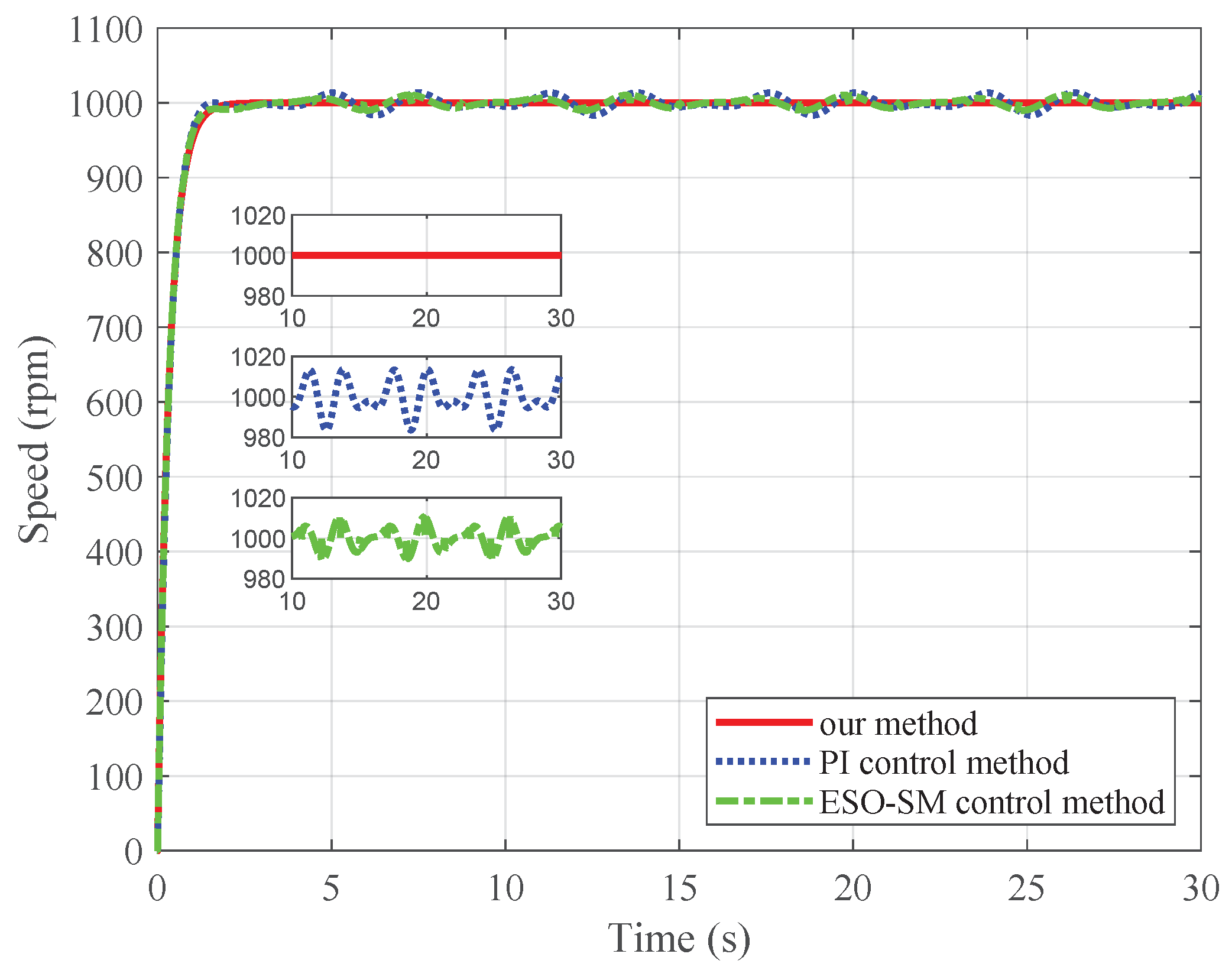
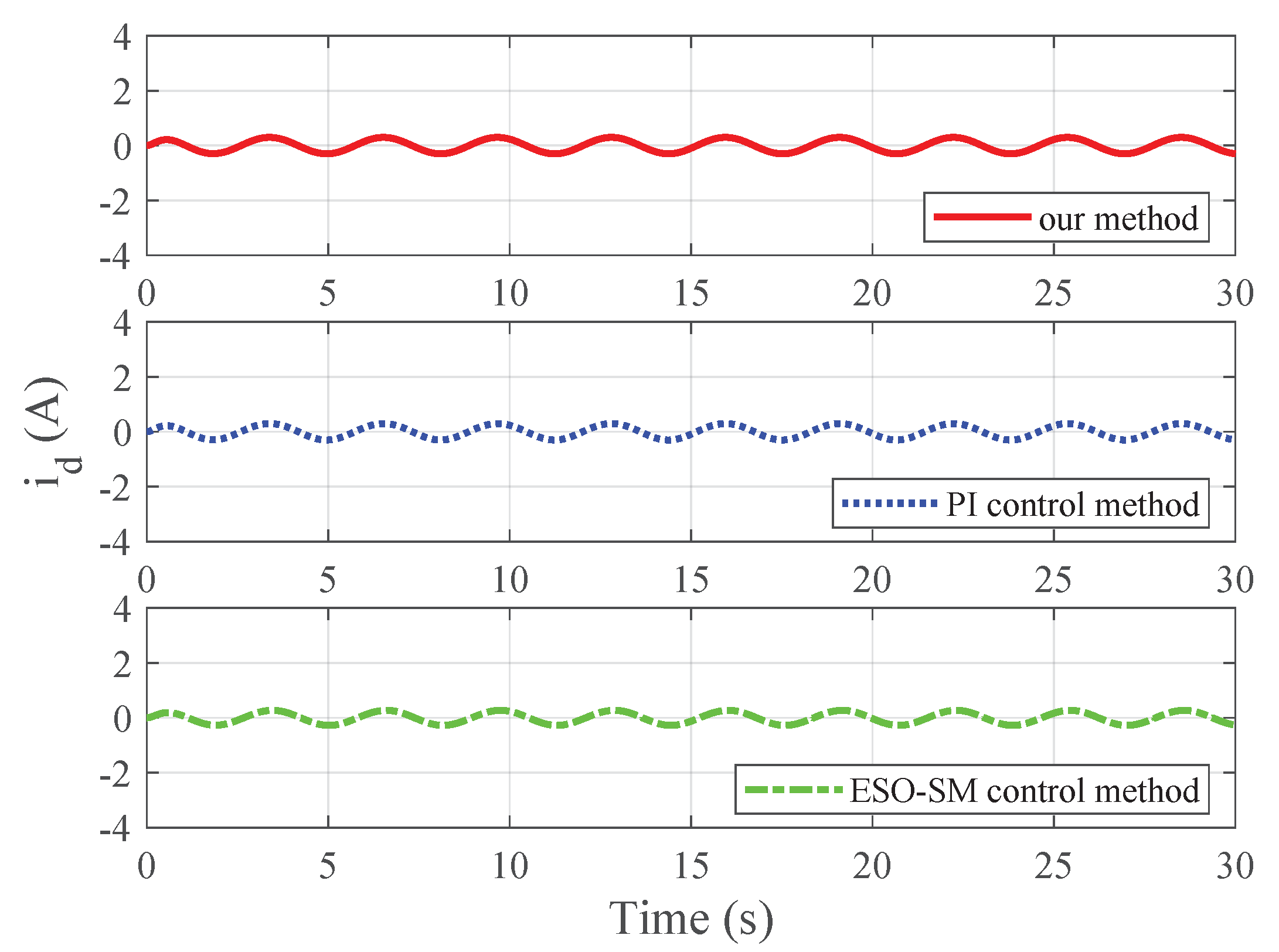
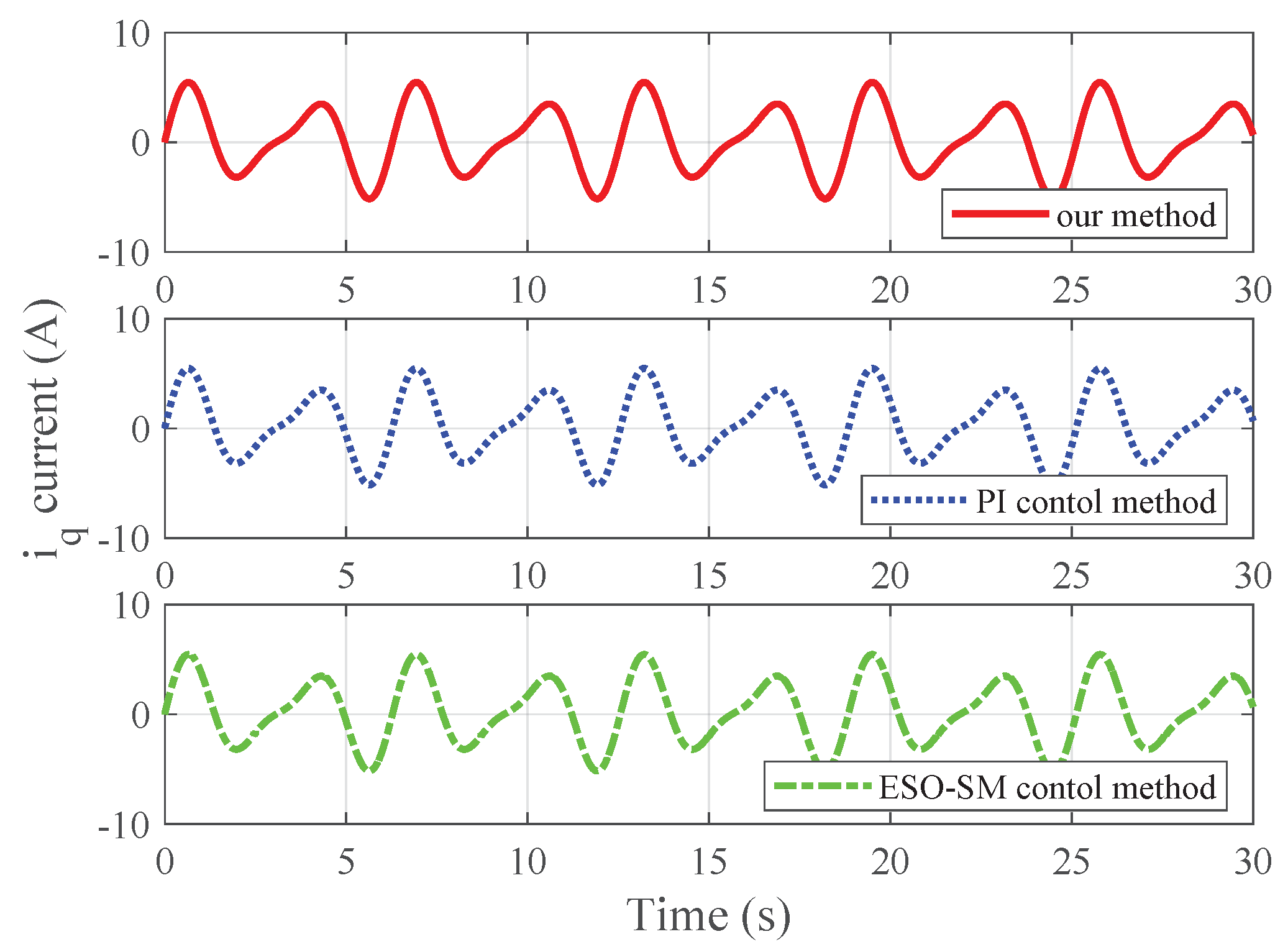
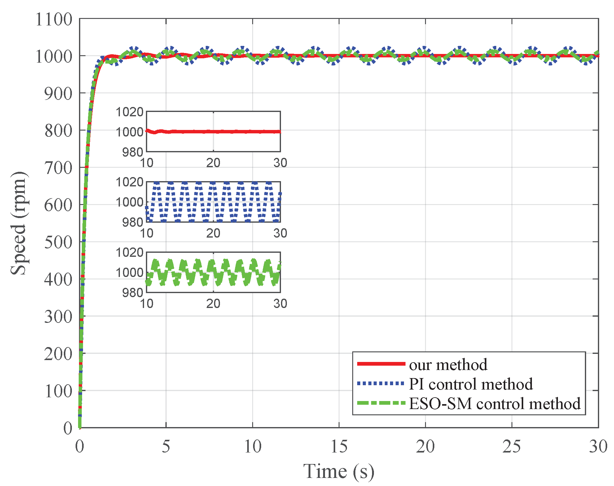
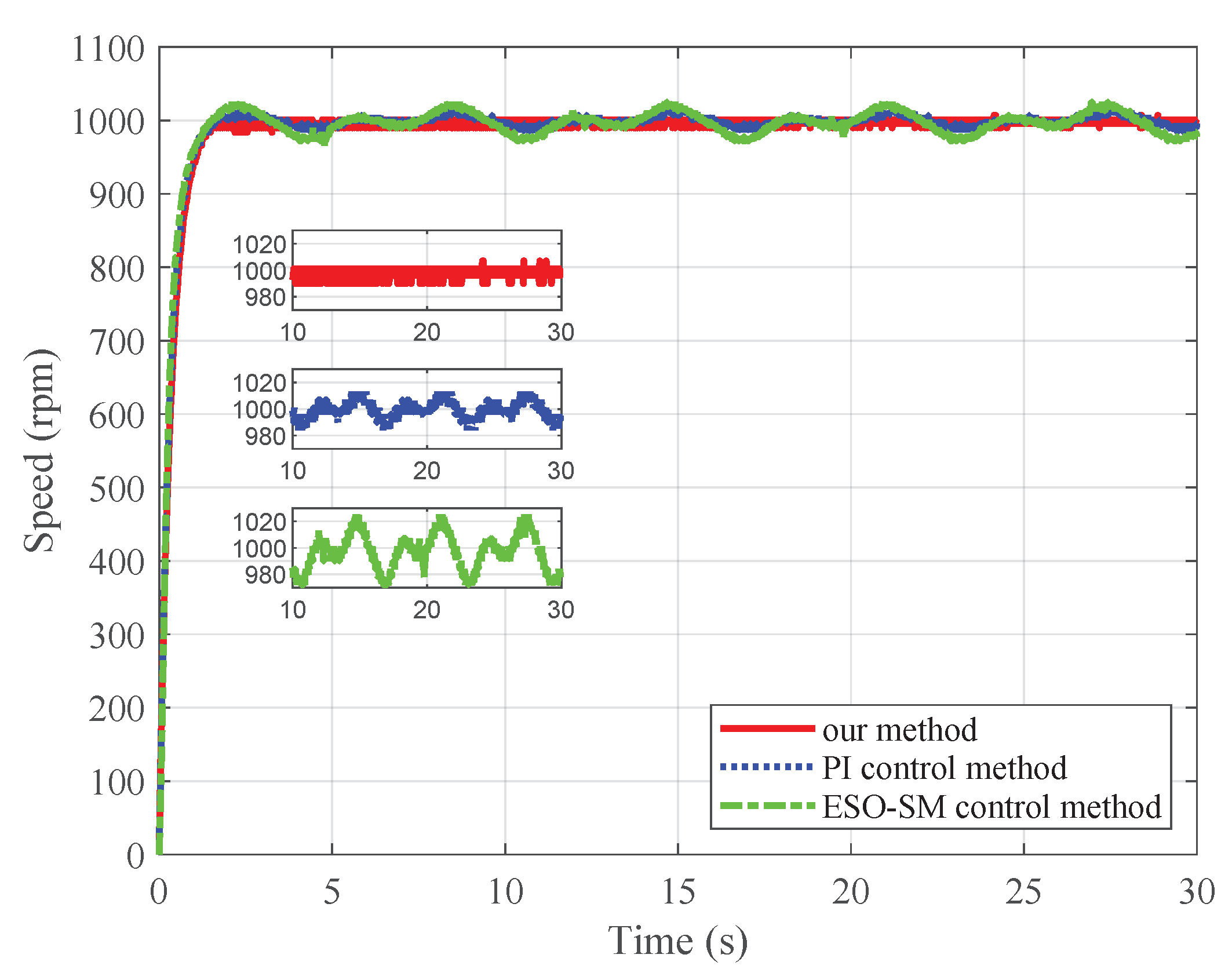
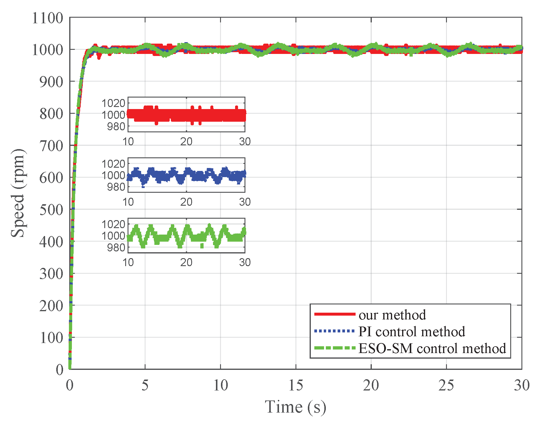
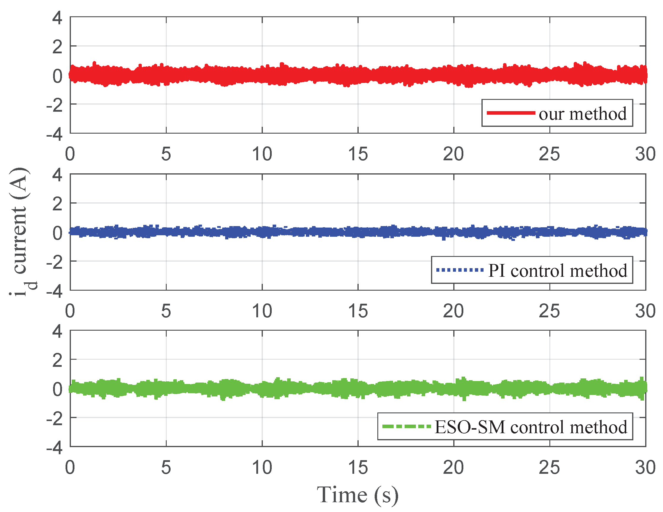
  • Our work is the first experimental study on a PMSM speed servo system to verify whether the time-varying internal-model-based adaptive controller in [21] is effective in practice. Compared with the PI control method and the ESO-SM control method [9], our method has higher speed tracking accuracy under load torque disturbance with unknown time-varying frequencies.
The rest of this article is organized as follows: In Section 2, the problem formulation is given. In Section 3, the specific controller design process for the PMSM speed servo system is given. In Section 4, the effectiveness of the proposed controller is verified by both simulation and experimental results. Section 5 concludes this article.

2. Problem Formulation

The model of surface-mounted PMSM in the d q rotating reference frame is as follows [24,27]:
d ω r d t = 3 p Φ v 2 J i q F v J ω r 1 J T L
d i d d t = R s L i d + p i q ω r + 1 L u d
d i q d t = R s L i q p i d ω r p Φ v L ω r + 1 L u q
where ω r denotes the rotor speed, u d , u q , i d , and i q are the voltage and current of d q axes, respectively, J is the rotational inertia, L is the d q axis inductance, p denotes the pole pairs, T L is the load torque, Φ v is the flux linkage, F v is the viscous friction coefficient, and R s is the stator resistance.
The control objective of this article is to construct a time-varying internal-model-based adaptive controller such that rotor speed ω r tracks the reference speed ω d precisely under parameter uncertainties and load torque disturbance with unknown time-varying frequencies and a stable closed-loop system. Like [7,9,25], in this article, the designed control structure is a cascaded control structure of speed–current loops. In the speed loop, a time-varying internal-model-based adaptive controller is adopted to regulate ω r to reference speed ω d . In the current loops, PI controllers are adopted to regulate i d current to zero and i q current to reference current i q * .
Let x = ω r . By regarding i q as the control input u, which will be adopted as the reference current of the q axis, the motion equation of system (1) can be described as
x ˙ = A x + B u + J 1 T L , e = x ω d
where A = F v / J , B = 3 p Φ v / ( 2 J ) , and e represents the speed tracking error.
It is assumed that the load torque T L and the reference speed ω d can be generated by the following time-varying exosystem:
τ ˙ = S ( t , σ ) τ , ω d = R τ , T L = Q τ
where S ( t , σ ) is a sufficiently smooth matrix with unknown constant σ and R and Q are constant matrices. It is assumed that the trajectory τ ( t ) of the exosystem is bound for any initial condition τ ( 0 ) . It should be noted that system (5) can generate not only a constant signal and multitone sine wave signals, but also periodic signals with time-varying frequencies.
Let c o l ( Φ v , F v , R s , L , J ) = c o l ( Φ ¯ v , F ¯ v , R ¯ s , L ¯ , J ¯ ) + ϵ , where ϵ R 5 denotes the parameter uncertainty and Φ ¯ v , F ¯ v , R ¯ s , L ¯ , and J ¯ are the nominal parameters of PMSM.
By combining (4) and (5), we can obtain the following system:
x ˙ = A x + B u J 1 Q τ , τ ˙ = S ( t , σ ) τ , e = x R τ .
Now, we can formulate the speed tracking control problem of PMSM as the adaptive output regulation problem of system (6) which aims to design a time-varying internal-model-based adaptive controller to guarantee that the trajectories of the closed-loop system are bound and the speed tracking error e converges to zero.

3. Controller Design

In this section, inspired by [21], a time-varying internal-model-based adaptive control method will be proposed to address the adaptive output regulation problem of system (6). The control diagram is shown in Figure 1, which can be achieved in the following two steps:
  • Construct a time-varying internal model and transform the adaptive output regulation problem of system (6) into the stabilization problem of the augmented system composed of system (6) and a time-varying internal model;
  • Design a stabilization controller to stabilize the augmented system and an adaptive law to handle the unknown parameters in the exosystem.
The regulator equations of system (4) are given as follows:
x ( t , τ , ϵ ) t + x ( t , τ , ϵ ) τ S ( t , σ ) τ = A x ( t , τ , ϵ ) + B u ( t , τ , ϵ , σ ) J 1 Q τ , 0 = x ( t , τ , ϵ ) R τ
where u ( t , τ , ϵ , σ ) and x ( t , τ , ϵ ) denote the steady-state input and steady-state state, respectively. We can obtain the following solutions of (7):
x ( t , τ , ϵ ) = R τ , u ( t , τ , ϵ , σ ) = B 1 ( A R + R S ( t , σ ) + J 1 Q ) τ .
Assumption 1.
There exists an integer s such that for all t , τ , ϵ , and σ, u ( t , τ , ϵ , σ ) satisfies
d s u ( t , τ , ϵ , σ ) d t s = b 0 ( t , σ ) u ( t , τ , ϵ , σ ) + d d t ( b 1 ( t , σ ) u ( t , τ , ϵ , σ ) ) + + d s 1 d t s 1 ( b s 1 ( t , σ ) u ( t , τ , ϵ , σ ) )
where b i ( t , σ ) are sufficiently smooth functions of t for i = 0 , , s 1 . Moreover, for sufficiently large l, b i ( t , σ ) and its j-th derivatives, j = 1 , , l , they are uniformly bound over [ 0 , ) . Additionally, there exists a smooth vector-valued function β ( t ) R ρ and vector-valued functions ψ i ( σ ) R ρ such that b i ( t , σ ) = ψ i ( σ ) β ( t ) .
Remark 1.
Assumption 1 is akin to Assumptions 3.2 and 3.3 in [21], which are used in the construction of a time-varying internal model. By [28], Assumption 1 automatically holds when exosystem (5) reduces to a linear time-invariant exosystem τ ˙ = S ( σ ) τ , ω d = R τ , T L = Q τ where all the eigenvalues of S ( σ ) are distinct with zero real parts for all σ and b i ( t , σ ) , i = 0 , 1 , , s 1 are constant values that do not depend on t. In practice, exosystem τ ˙ = S ( σ ) τ , ω d = R τ , T L = Q τ can generate many typical signals including a constant signal, step signal, and sinusoidal signal.
Let
ξ ( t , τ , ϵ , σ ) = ξ 1 ξ 2 ξ s 1 ξ s = u ( t , τ , ϵ , σ ) b s 1 ( t , σ ) u ( t , τ , ϵ , σ ) + ξ ˙ 1 b 2 ( t , σ ) u ( t , τ , ϵ , σ ) + ξ ˙ s 2 b 1 ( t , σ ) u ( t , τ , ϵ , σ ) + ξ ˙ s 1 .
Then, for all τ , ϵ , and σ , we can obtain the following system:
ξ ˙ ( t , τ , ϵ , σ ) = Φ 0 ( t , σ ) ξ ( t , τ , ϵ , σ ) , u ( t , τ , ϵ , σ ) = Γ 0 ξ ( t , τ , ϵ , σ )
where
Φ 0 ( t , σ ) = b s 1 ( t , σ ) 1 0 0 b s 2 ( t , σ ) 0 1 0 b 1 ( t , σ ) 0 0 1 b 0 ( t , σ ) 0 0 0
and Γ 0 = 1 0 0 .
Similar to [21], Φ 0 ( t , σ ) can be redescribed as
Φ 0 ( t , σ ) = Φ b + b ( t , σ ) Γ 0
where
Φ b = 0 1 0 0 0 0 1 0 0 0 0 1 0 0 0 0 , b ( t , σ ) = b s 1 ( t , σ ) b s 2 ( t , σ ) b 1 ( t , σ ) b 0 ( t , σ ) .
It is worth mentioning that ( Φ b , Γ 0 ) is observable. Hence, there exists a vector L 0 R s such that F 0 = Φ b L 0 Γ 0 R s × s is a Hurwitz matrix.
Let G 0 ( t , σ ) = L 0 + b ( t , σ ) . By Assumption 1, let
Ψ ( σ ) = ψ s 1 ( σ ) ψ 0 ( σ ) .
Then, b ( t , σ ) = Ψ ( σ ) β ( t ) such that G 0 ( t , σ ) = L 0 + Ψ ( σ ) β ( t ) .
Next, let β 0 ( t ) = 1 and denote L i ( σ ) = c o l ( ψ ( s 1 ) i , , ψ 0 i ) where ψ m i is the i-th component of ψ m ( σ ) for m = 0 , , s 1 , and β ( t ) = c o l ( β 1 ( t ) , , β ρ ( t ) ) , where β i ( t ) is a scalar function. Then, we can obtain
G 0 ( t , σ ) = L 0 β 0 ( t ) + L 1 ( σ ) β 1 ( t ) + + L ρ ( σ ) β ρ ( t ) .
Also, let
F g = F 0 0 0 0 0 F 0 0 0 0 0 0 0 0 0 F 0 , G g ( t ) = Γ 0 β 0 ( t ) Γ 0 β 1 ( t ) Γ 0 β ρ ( t ) , H g ( σ ) = L 0 L 1 ( σ ) L ρ ( σ ) .
According to Proposition 3.2 in [21], there exists a continuously differentiable matrix T ( t , σ ) R l ( ρ + 1 ) × l with constant rank l, such that
T ˙ ( t , σ ) + T ( t , σ ) Φ 0 ( t , σ ) = ( F g + G g ( t ) H g ( σ ) ) T ( t , σ ) , Γ 0 = H g ( σ ) T ( t , σ ) .
Let θ ( t , τ , ϵ , σ ) = T ( t , σ ) ξ ( t , τ , ϵ , σ ) . System (10) becomes
θ ˙ ( t , τ , ϵ , σ ) = ( F g + G g ( t ) H g ( σ ) ) θ ( t , τ , ϵ , σ ) , u ( t , τ , ϵ , σ ) = H g ( σ ) θ ( t , τ , ϵ , σ ) .
Based on (14), the time-varying internal model of system (6) can be constructed as follows:
η ˙ = F g η + G g ( t ) u .
Performing the following transformation
e = x x ( t , τ , ϵ ) , η ˜ = η θ ( t , τ , ϵ , σ ) G g ( t ) B 1 e
on the augmented system comprising (6) and (15) gives
η ˜ ˙ = F g η ˜ + ( F g G g ( t ) G ˙ g ( t ) A G g ( t ) ) B 1 e , e ˙ = ( A + H g ( σ ) G g ( t ) ) e + H g ( σ ) B η ˜ + B ( u H g ( σ ) η ) .
Now, the adaptive output regulation problem of system (6) is transformed into the robust stabilization problem of system (17).
Theorem 1.
Under Assumption 1, the following adaptive control law
u = k e + H ^ g η , η ˙ = F g η + G g ( t ) u , H ^ ˙ g = η e
where H ^ g is the estimation of H g ( σ ) , solves the adaptive output regulation problem of system (6).
Proof. 
Let
U ( η ˜ , e , H ˜ g ) = m η ˜ P η ˜ + 1 2 e 2 + B 2 H ˜ g H ˜ g
where H ˜ g = H ^ g H g ( σ ) , P is a positive definite matrix satisfying F g P + P F g = I , and m is certain positive number. Then,
U ˙ m η ˜ 2 + 2 m η ˜ P ( F g G g ( t ) G ˙ g ( t ) A G g ( t ) ) B 1 e + e [ ( A + H g ( σ ) G g ( t ) k B ) e + H g ( σ ) B η ˜ ] + e B H ˜ g η + B H ˜ g H ˜ ˙ g T 3 4 m η ˜ 2 + 4 m P ( F g G g ( t ) G ˙ g ( t ) A G g ( t ) ) B 1 2 e 2 + A + H g ( σ ) G g ( t ) + 1 4 k B e 2 + H g ( σ ) B 2 η ˜ 2 3 4 m + H g ( σ ) B 2 η ˜ 2 + ( A + H g ( σ ) G g ( t ) + 1 4 k B + 4 m P ( F g G g ( t ) G ˙ g ( t ) A G g ( t ) ) B 1 2 ) e 2 .
Let m 4 ( H g ( σ ) B 2 + 1 ) / 3 and
k B 1 4 m P ( F g G g ( t ) G ˙ g ( t ) A G g ( t ) ) B 1 2 + A + H g ( σ ) G g ( t ) + 5 / 4 .
Inequality (20) becomes
U ˙ η ˜ 2 e 2 .
By (19) and (21), the trajectories of the closed-loop system consisting of (6) and (18) are bound. In addition, by (17), e ˙ is bound; hence, e is uniformly continuous. By Barbalat’s lemma, lim t e ( t ) = 0 . Consequently, the adaptive output regulation problem of system (6) can be solved by the controller (18). □
Remark 2.
In this article, the stability of the augmented system composed of system (6) and time-varying internal model (15) is analyzed by Lyapunov’s stability theorem. Both Lyapunov’s stability theorem and the small-gain theorem are important theorems used for analyzing system stability in control theory. The method of the nonlinear small-gain theorem has been widely utilized to solve various control problems [29,30,31]. As mentioned in [28], the small-gain theorem and the internal model control method were combined to solve the global robust output regulation problem for the nonlinear systems in lower triangular form. It is interesting to combine the small-gain theorem with the time-varying internal model approach to solve the output regulation problem of PMSM.

4. Simulation and Experimental Results

In this section, we will present the simulation and experimental results of our method. In addition, we compare our method with the PI control method and the ESO-SM control method [9]. Figure 2 and Figure 3 illustrate the control diagrams of two comparative methods. The nominal parameters of PMSM are J ¯ = 0.0000189 K g m 2 , p = 4 , F ¯ v = 0.0001 N m s / r a d , Φ ¯ v = 0.0128 V s / r a d , L ¯ = 0.00045 H, and R ¯ s = 0.33 Ω .
Next, a brief description of the ESO-SM control method [9] is given as follows:
First, the ESO is constructed as
e 1 = ω ^ e ω e , ω ^ ˙ e = f ^ t d β 01 e 1 + a ¯ 0 i q c ¯ 0 ω e , f ^ ˙ t d = β 02 e 1
where ω e = p ω r , f t d represents the unknown total disturbance, a ¯ s = 3 p ¯ 2 Φ ¯ v / ( 2 J ¯ ) , b ¯ s = F ¯ v / J ¯ , f ^ t d and ω ^ e are the estimation of f t d and ω e , respectively, β 01 = 2 ω 0 , β 02 = ω 0 2 , and ω 0 denotes the bandwidth of the ESO.
Then, i q * is designed as
i q * = γ σ ω η s g n ( σ ω ) 1 a ¯ 0 f ^ t d
where η = ( 1 / a ¯ s ) ( b ¯ s ω e + c ω e ω ) , c ω > 0 , γ > 0 , σ ω = e ω + c ω o t e ω d τ , e ω = ω e p ω d .

4.1. Simulation Results

To validate the robustness, the actual motor parameters are selected as R s = 1.8 R ¯ s , Φ v = 0.7 Φ ¯ v , L = 1.6 L ¯ , F v = 0.8 F ¯ v , and J = 1.2 J ¯ . The initial values are ω r ( 0 ) = 0 rad/s, i d ( 0 ) = 0.05 A, i q ( 0 ) = 0.4 A, η ( 0 ) = 0 , and H ^ g ( 0 ) = 0 .
The simulation validation is conducted under two different situations as follows:
Case 1: Reference speed 1000 rpm and load torque T L = 0.2cos ( σ cos ( t ) ) + 0.1sin ( σ cos ( t ) ) N·m
It should be noted that the reference speed ω d and the load torque T L can be generated by exosystem (5) with
S ( t , σ ) = 0 0 0 0 0 σ sin ( t ) 0 σ sin ( t ) 0 , R = 1 0 0 , Q = 0 1 0
where σ = 2 . By solving the regulator equations of system (4), we obtain the steady-state input u ( t , τ , ϵ , σ ) = B 1 ( A R + J 1 Q ) τ . Therefore, Assumption 1 holds with s = 5 , b 4 ( t , σ ) = 0 , b 3 ( t , σ ) = 5 σ 2 sin 2 ( t ) , b 2 ( t , σ ) = 3 σ 2 sin ( t ) cos ( t ) , b 1 ( t , σ ) = 7 + σ 2 sin 2 ( t ) , and b 0 ( t , σ ) = 0 . The design parameters of the proposed controller are k = 4 and
F g = F 0 0 0 0 0 F 0 0 0 0 0 F 0 0 0 0 0 F 0 , G g ( t ) = Γ 0 Γ 0 Γ 0 T sin 2 ( t ) Γ 0 sin ( t ) cos ( t )
where
F 0 = 15 1 0 0 0 8 0 1 0 0 5 0 0 1 0 3 0 0 0 1 2 0 0 0 0 , Γ 0 = 1 0 0 0 0 .
Furthermore, the parameters of the ESO-SM controller are set as γ = 0.3 , ω 0 = 7 , and c ω = 20 . The PI speed controller parameters are set as K P 1 = 6 and K I 1 = 15 . The design parameters of the PI current loop are the same for the three control methods, which are set as K P 2 = 6 , K I 2 = 15 , K P 3 = 6 , and K I 3 = 15 . In particular, K P i and K I i are the proportional gain and the integral gain of the P I i controller, where i = 1 , 2 , 3 . In addition, by [32], a linear tracking differentiator n ˙ 1 = δ ( n 1 ω d ) is adopted to prevent overlarge voltage during the motor startup phase, where n 1 is the desired speed trajectory and δ = 3 . Figure 4, Figure 5 and Figure 6 illustrate the speed tracking trajectories, i d current, and i q current for case 1, respectively.
Case 2: Reference speed ω d = 1000 rpm and load torque T L = 0.3sin ( 3 t ) N·m
It should be noted that the reference speed ω d and the load torque T L can be generated by linear time-invariant exosystem τ ˙ = S ( σ ) τ , ω d = R τ , T L = Q τ with
S ( σ ) = 0 0 0 0 0 σ 0 σ 0 , R = 1 0 0 , Q = 0 1 0 ,
where σ = 3 . By solving the regulator equations of system (4), we obtain the steady-state input u ( τ , ϵ , σ ) = B 1 ( A R + J 1 Q ) τ . Therefore, Assumption 1 holds with s = 3 , b 2 ( t , σ ) = 0 , and b 1 ( t , σ ) = σ 2 , b 0 ( t , σ ) = 0 . The design parameters of our controller are
F g = 60 20 10 1 0 0 0 1 0 , G g ( t ) = 1 0 0 ,
and k = 25 . Additionally, the parameters of the ESO-SM controller are set as γ = 4 , ω 0 = 9 , and c ω = 12 . The PI speed controller parameters are set as K P 1 = 6 and K I 1 = 15 . The PI current loop design parameters of three control methods are K P 2 = 8, K I 2 = 12, K P 3 = 8, and K I 3 = 12. Figure 7, Figure 8 and Figure 9 illustrate the speed tracking trajectories, i d current, and i q current for case 2, respectively.
To quantitatively compare the steady-state and transient performance of the three methods, some performance indices such as maximal steady-state speed error (MSSSE), overshoot, and setting time (with a 5 % error bound) are given in Table 1. From the simulation results, it can be seen that our method exhibits the smallest steady-state speed error among the three methods under parameter uncertainties and load torque disturbance with unknown time-varying frequencies.

4.2. Experimental Results

Besides the simulation results, the proposed controller is also verified by the real-time experimental setup shown in Figure 10. In the experimental setup, the sampling time of the speed loop is 1 ms, and the sampling time of the current loop is 0.05 ms. The solver used in Simulink R2009b is discrete (no continuous states). More detailed information about the experimental setup can be found in [24].
The experimental validation is conducted under two different situations as follows:
Case 1: Reference speed 1000 rpm and load torque T L = 0.2cos ( σ cos ( t ) ) + 0.1sin ( σ cos ( t ) ) N·m
It should be noted that the reference speed ω d and the load torque T L can be generated by exosystem (5). In a similar manner to the simulation part, it can be verified that Assumption 1 holds. The design parameters of the proposed controller are k = 27 and
F g = F 0 0 0 0 0 F 0 0 0 0 0 F 0 0 0 0 0 F 0 , G g ( t ) = Γ 0 Γ 0 Γ 0 T sin 2 ( t ) Γ 0 sin ( t ) cos ( t )
where
F 0 = 40 1 0 0 0 30 0 1 0 0 15 0 0 1 0 8 0 0 0 1 5 0 0 0 0 , Γ 0 = 1 0 0 0 0 .
Furthermore, the design parameters of the ESO-SM controller are set as γ = 0.7 , ω 0 = 0.05 , and c ω = 4 . The PI speed controller parameters are set as K P 1 = 2 and K I 1 = 6 . The design parameters of the PI current loop are the same for the three control methods, which are set as K P 2 = 2 , K I 2 = 6 , K P 3 = 2 , and K I 3 = 6 . Similarly, we also use the same linear tracking differentiator as the simulation part to avoid the overvoltage at the startup stage. Figure 11, Figure 12 and Figure 13 illustrate the speed tracking trajectories, i d current, and i q current for case 1, respectively.
Case 2: Reference speed ω d = 1000 rpm and load torque T L = 0.3sin ( 3 t ) N·m
It should be noted that the reference speed ω d and the load torque T L can be generated by linear time-invariant exosystem τ ˙ = S ( σ ) τ , ω d = R τ , T L = Q τ with
S ( σ ) = 0 0 0 0 0 σ 0 σ 0 , R = 1 0 0 , Q = 0 1 0 ,
where σ = 3 . In a similar manner as the simulation part, it can be verified that Assumption 1 holds. The design parameters of our controller are
F g = 32 17 5 1 0 0 0 1 0 , G g ( t ) = 1 0 0 ,
and k = 18 . In addition, the parameters of the ESO-SM controller are set as γ = 6 , ω 0 = 6 , and c ω = 44 . The PI speed controller parameters are set as K P 1 = 15 and K I 1 = 25 . The PI current loop design parameters of three control methods are K P 2 = 10, K I 2 = 25, K P 3 = 10, and K I 3 = 25. Figure 14, Figure 15 and Figure 16 illustrate the speed tracking trajectories, i d current, and i q current for case 2, respectively.
The MSSSE, overshoot, and settling time for the three control methods are shown in Table 2. From the experimental results, it can be observed that our method exhibits the smallest steady-state speed tracking error compared with the other two methods under load torque disturbance with unknown time-varying frequencies. It should be noted that only our method has no overshoot among the three control methods. It is worth mentioning that the time delay is neglected in this article, which may cause the control error in the experiment [33].

5. Conclusions

In this article, we have solved the adaptive output regulation problem of the PMSM speed servo system under load torque disturbance with unknown time-varying frequencies. A time-varying internal-model-based adaptive speed control method was proposed, which can achieve high-precision speed tracking under parameter uncertainties and load torque disturbance with unknown time-varying frequencies. Both simulation and experimental results have demonstrated that, compared with the PI control method and the ESO-SM control method, our method exhibits the smallest steady-state speed tracking error under unknown time-varying load torque disturbance.

Author Contributions

H.S.: investigation, writing—original draft. Z.P.: investigation, methodology, funding acquisition. J.H.: investigation, methodology, supervision. Y.H.: supervision, funding acquisition. J.-G.L.: supervision, funding acquisition. All authors have read and agreed to the published version of the manuscript.

Funding

This work was funded by the National Natural Science Foundation of China (62273127 and 62073217), the Dreams Foundation of Jianghuai Advance Technology Center (2023-ZM01J006), and the Anhui Provincial Key Research and Development Project (2022a05020025).

Data Availability Statement

The original contributions presented in the study are included in the article. Further inquiries can be directed to the corresponding author.

Conflicts of Interest

The authors declare no conflicts of interest.

Correction Statement

This article has been republished with a minor correction to the title. This change does not affect the scientific content of the article.

References

  1. Rafaq, M.S.; Jung, J.W. A comprehensive review of state-of-the-art parameter estimation techniques for permanent magnet synchronous motors in wide speed range. IEEE Trans. Ind. Inform. 2020, 16, 4747–4758. [Google Scholar]
  2. Teymoori, V.; Kamper, M.; Wang, R.J.; Kennel, R. Sensorless control of dual three-phase permanent magnet synchronous machines—A review. Energies 2023, 16, 1326. [Google Scholar] [CrossRef]
  3. Kifayat, U.; Jaroslaw, G.; Adeel, F.M. Critical review on robust speed control techniques for permanent magnet synchronous motor (PMSM) speed regulation. Energies 2022, 15, 1235. [Google Scholar] [CrossRef]
  4. Zhao, J.G.; Yang, C.Y.; Gao, W.N.; Zhao, L.N. Reinforcement learning and optimal control of PMSM speed servo system. IEEE Trans. Ind. Electron. 2023, 70, 8305–8313. [Google Scholar]
  5. Chen, P.C.; Luo, Y. Analytical fractional-order PID controller design with Bode’s ideal cutoff filter for PMSM speed servo system. IEEE Trans. Ind. Electron. 2023, 70, 1783–1793. [Google Scholar]
  6. Nguyen, H.T.; Jung, J.W. Finite control set model predictive control to guarantee stability and robustness for surface-mounted PM synchronous motors. IEEE Trans. Ind. Electron. 2018, 65, 8510–8519. [Google Scholar]
  7. Yin, Y.F.; Liu, L.; Vazquez, S.; Xu, R.Q.; Dong, Z.J.; Liu, J.X.; Leon, J.I.; Wu, L.G.; Franquelo, L.G. Disturbance and uncertainty attenuation for speed regulation of PMSM servo system using adaptive optimal control strategy. IEEE Trans. Transp. Electrif. 2023, 9, 3410–3420. [Google Scholar]
  8. Yan, Y.D.; Yang, J.; Sun, Z.X.; Zhang, C.L.; Li, S.H.; Yu, H.Y. Robust speed regulation for PMSM servo system with multiple sources of disturbances via an augmented disturbance observer. IEEE/ASME Trans. Mechatron. 2018, 23, 769–780. [Google Scholar]
  9. Qu, L.Z.; Qiao, W.; Qu, L.Y. An extended-state-observer-based sliding-mode speed control for permanent-magnet synchronous motors. IEEE J. Emerg. Sel. Top. Power Electron. 2021, 9, 1605–1613. [Google Scholar]
  10. Khanh, P.Q.; Anh, H.P. Novel sensorless PMSM speed control using advanced fuzzy MRAS algorithm. Arab. J. Sci. Eng. 2022, 47, 14531–14542. [Google Scholar]
  11. Zhu, L.H.; Zhang, G.Q.; Jing, R.Z.; Bi, G.D.; Xiang, R.H.; Wang, G.L.; Xu, D.G. Nonlinear active disturbance rejection control strategy for permanent magnet synchronous motor drives. IEEE Trans. Energy Convers. 2022, 37, 2119–2129. [Google Scholar]
  12. Gao, Y.X.; Yin, Z.G.; Zhang, Y.P.; Zhang, Y.Q.; Yuan, D.S.; Liu, J. Surface-mounted permanent magnet synchronous motor servo system speed control using antidisturbance enhanced finite-time composite control. IEEE Trans. Power Electron. 2024, 39, 9996–10008. [Google Scholar]
  13. Isidori, A.; Marconi, L.; Serrani, A. Robust Autonomous Guidance: An Internal Model-Based Approach; Springer: London, UK, 2003. [Google Scholar]
  14. Huang, J. Nonlinear Output Regulation: Theory and Applications; SIAM: Philadelphia, PA, USA, 2004. [Google Scholar]
  15. Chen, Z.Y.; Huang, J. Stabilization and Regulation of Nonlinear Systems: A Robust and Adaptive Approach; Springer: Cham, Switzerland, 2015. [Google Scholar]
  16. Bin, M.; Astolfi, D.; Marconi, L. About robustness of control systems embedding an internal model. IEEE Trans. Autom. Control 2023, 68, 1306–1320. [Google Scholar]
  17. Lei, Y.; Hua, T.; Wang, Y.W.; Park, J.H. Robust output regulation of singularly perturbed systems by event-triggered output feedback. IEEE Trans. Syst. Man Cybern. Syst. 2024, 54, 2104–2113. [Google Scholar]
  18. Liu, L.; Chen, Z.Y.; Huang, J. Global disturbance rejection of lower triangular systems with an unknown linear exosystem. IEEE Trans. Autom. Control 2011, 56, 1690–1695. [Google Scholar]
  19. Tomei, P.; Marino, R. Adaptive regulation for minimum phase systems with unknown relative degree and uncertain exosystems. Automatica 2023, 147, 110678. [Google Scholar]
  20. Zhang, Z.; Serrani, A. Adaptive robust output regulation of uncertain linear periodic systems. IEEE Trans. Autom. Control 2009, 54, 266–278. [Google Scholar]
  21. Yang, X.; Huang, J. A framework for nonlinear output regulation for time-varying uncertain systems. In Proceedings of the 49th IEEE Conference on Decision and Control, Atlanta, GA, USA, 15–17 December 2010; pp. 5396–5401. [Google Scholar]
  22. Zhang, M.T.; Liu, Z.T.; Su, H.Y. Precise disturbance rejection for dynamic wireless charging system of electric vehicle using internal model-based regulator with disturbance observer. IEEE Trans. Ind. Electron. 2024, 71, 7695–7705. [Google Scholar]
  23. Wu, H.W.; Xu, D.B. Attitude regulation of flexible spacecrafts with unknown control directions and input disturbances. J. Syst. Sci. Complex. 2024, 37, 2347–2367. [Google Scholar]
  24. Ping, Z.W.; Li, Y.Y.; Song, Y.; Huang, Y.Z.; Wang, H.; Lu, J.-G. Nonlinear speed tracking control of PMSM servo system: A global robust output regulation approach. Control Eng. Pract. 2021, 112, 104832. [Google Scholar]
  25. Ping, Z.W.; Jia, Y.J.; Xiong, B.G.; Zhang, H.W.; Lu, J.-G. Optimal output regulation for PMSM speed servo system using approximate dynamic programming. Sci. China-Inf. Sci. 2023, 66, 170206. [Google Scholar] [CrossRef]
  26. Zhang, L.; Chen, Z.Y.; Yu, X.H.; Yang, J.; Li, S.H. Sliding-mode-based robust output regulation and its application in PMSM servo systems. IEEE Trans. Ind. Electron. 2023, 70, 1852–1860. [Google Scholar] [CrossRef]
  27. Zhu, G.C.; Dessaint, L.A.; Akhrif, O.; Kaddouri, A. Speed tracking control of a permanent-magnet synchronous motor with state and load torque observer. IEEE Trans. Ind. Electron. 2000, 47, 346–355. [Google Scholar]
  28. Huang, J.; Chen, Z.Y. A general framework for tackling output regulation problem. IEEE Trans. Autom. Control 2004, 49, 2203–2218. [Google Scholar] [CrossRef]
  29. Liu, T.F.; Jiang, Z.-P. Event-based control of nonlinear systems with partial state and output feedback. Automatica 2015, 53, 10–22. [Google Scholar]
  30. Liu, T.F.; Qin, Z.Y.; Hong, Y.G.; Jiang, Z.-P. Distributed optimization of nonlinear multiagent systems: A small-gain approach. IEEE Trans. Autom. Control 2022, 67, 676–691. [Google Scholar]
  31. Jin, Z.H.; Li, H.; Qin, Z.Y.; Wang, Z.X. Gradient-free cooperative source-seeking of quadrotor under disturbances and communication constraints. IEEE Trans. Ind. Electron. 2025, 72, 1969–1979. [Google Scholar]
  32. Han, J.Q.; Wang, W. Nonlinear tracking differentiator. J. Syst. Sci. Math. Sci. 1994, 14, 177–183. [Google Scholar]
  33. Morteza, M.; Arman, K.; Mojtaba, G.; Payam, S.; Sami, A. A Discrete approach to feedback linearization, yaw control of an unmanned helicopter. Unmanned Syst. 2023, 11, 57–66. [Google Scholar]
Figure 1. Control diagram of the time-varying internal-model-based adaptive controller.
Actuators 14 00158 g001
Figure 2. Control diagram of PI controller.
Actuators 14 00158 g002
Figure 3. Control diagram of ESO-SM controller.
Actuators 14 00158 g003
Figure 4. Simulated speed tracking trajectories for case 1.
Actuators 14 00158 g004
Figure 5. Simulated i d current for case 1.
Actuators 14 00158 g005
Figure 6. Simulated i q current for case 1.
Actuators 14 00158 g006
Figure 7. Simulated speed tracking trajectories for case 2.
Actuators 14 00158 g007
Figure 8. Simulated i d current for case 2.
Actuators 14 00158 g008
Figure 9. Simulated i q current for case 2.
Actuators 14 00158 g009
Figure 10. Experimental setup.
Actuators 14 00158 g010
Figure 11. Experimental speed tracking trajectories for case 1.
Actuators 14 00158 g011
Figure 12. Experimental i d current for case 1.
Actuators 14 00158 g012
Figure 13. Experimental i q current for case 1.
Actuators 14 00158 g013
Figure 14. Experimental speed tracking trajectories for case 2.
Actuators 14 00158 g014
Figure 15. Experimental i d current for case 2.
Actuators 14 00158 g015
Figure 16. Experimental i q current for case 2.
Actuators 14 00158 g016
Table 1. Major performance comparison by simulation.
Control MethodsMSSSE (rpm)Overshoot (%)Settling Time (s)
Case 1our controller0.401.035
PI controller2100.912
ESO-SM controller1500.926
Case 2our controller0.601.023
PI controller2500.885
ESO-SM controller1700.934
Table 2. Major performance comparison by experiment.
Control MethodsMSSSE (rpm)Overshoot (%)Settling Time (s)
Case 1our controller501.113
PI controller220.60.928
ESO-SM controller141.80.965
Case 2our controller701.132
PI controller250.80.954
ESO-SM controller151.20.973
Disclaimer/Publisher’s Note: The statements, opinions and data contained in all publications are solely those of the individual author(s) and contributor(s) and not of MDPI and/or the editor(s). MDPI and/or the editor(s) disclaim responsibility for any injury to people or property resulting from any ideas, methods, instructions or products referred to in the content.

