
Three-Vector-Based Smart Model Predictive Torque Control of Surface-Mounted Permanent Magnet Synchronous Motor Drives for Robotic System Based on Genetic Algorithm


Abstract
1. Introduction
2. Conventional FCS-MPC of an SPMSM Drive System
2.1. SPMSM Mathematical Model
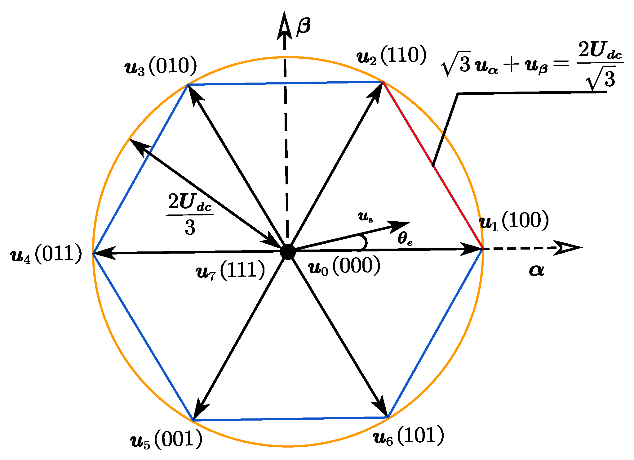
2.2. Model of Inverter
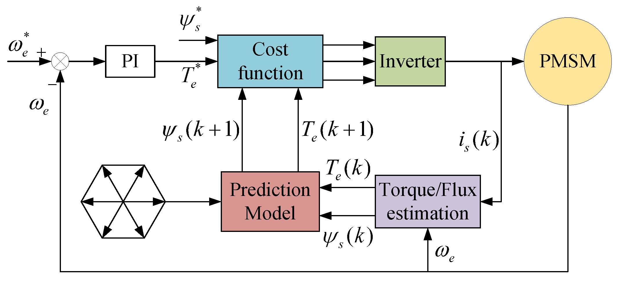
2.3. Convention FCS-MPTC
3. Proposed Control Method
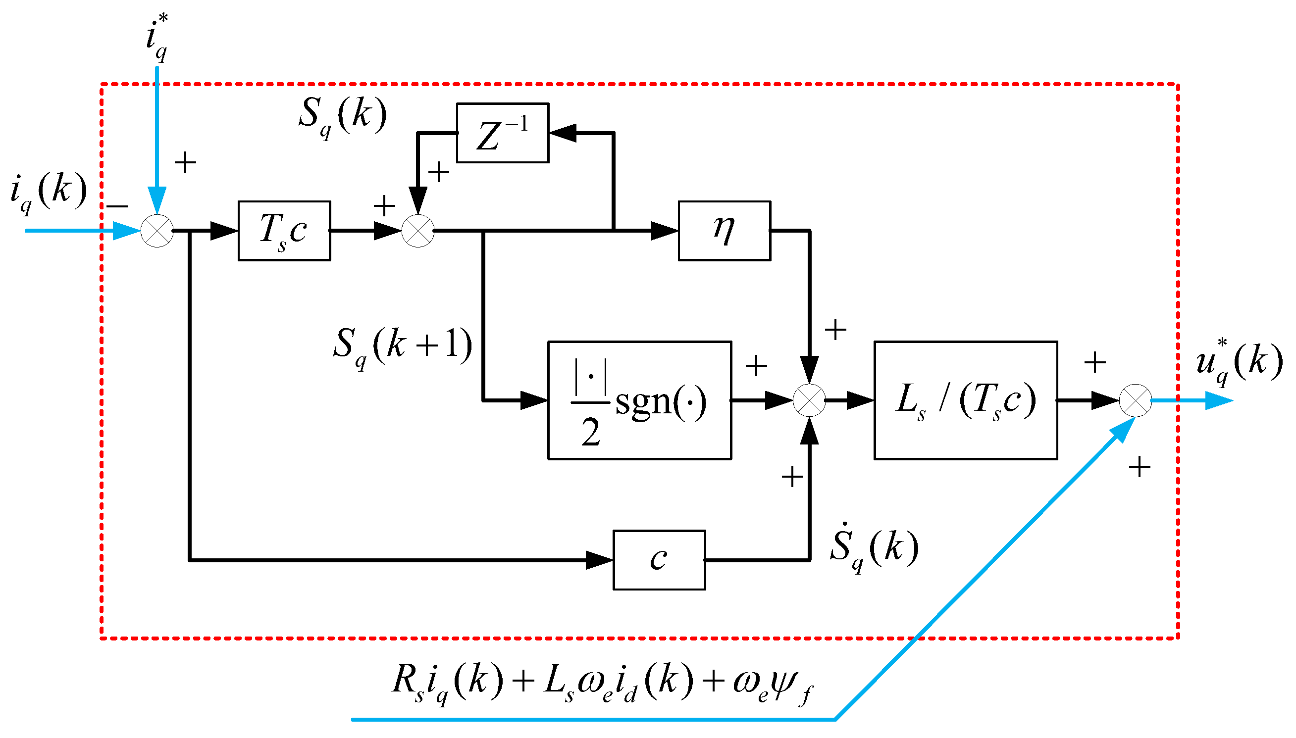
3.1. DTSM Current Controller
3.2. Predictive Control with the Optimal Vector Sequence
3.3. MPTC Multi-Objective Optimization
- (1)
- An initial population of individuals is generated.
- (2)
- new individuals are generated from the initial population by crossover.
- (3)
- In order to prevent a local optimum, new individuals are then generated by random mutation.
- (4)
- All the individuals from the first three steps are sorted in a non-dominated order to pick the current Pareto solution set. If the current Pareto solution set is larger than , the crowding distance of each optimal solution is calculated, and then some of the solutions with a small crowding distance are eliminated. The remaining individuals are used as the initial population for the next cycle.
- (5)
- Until it reaches the criteria for stopping, the algorithm will continue.
- (1)
- According to (17), we can obtain the reference voltage .
- (2)
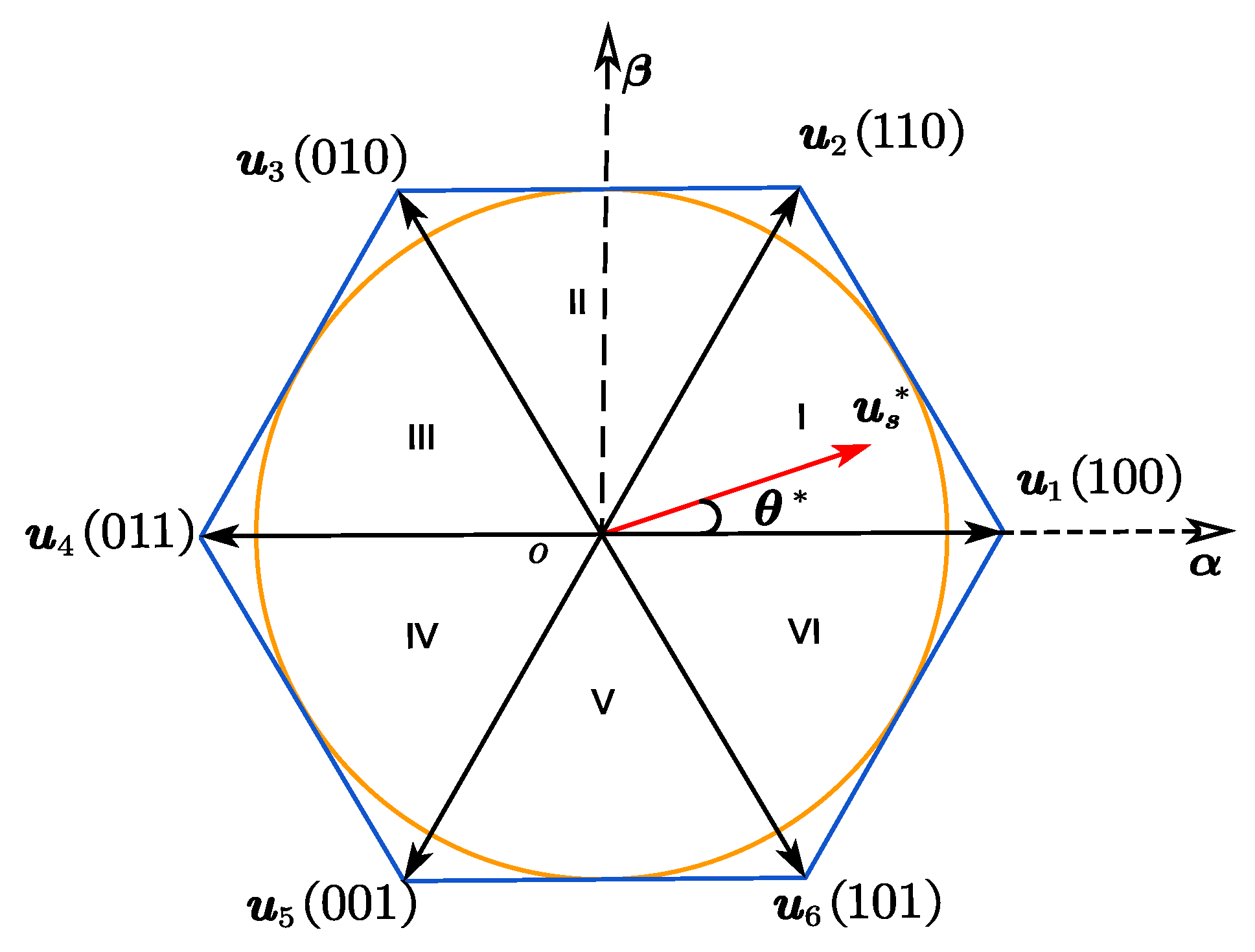
- The phase angle can be obtained by (20).
- (3)
- According to Table 1, three target vectors are selected at the kth period.
- (4)
- (5)
- The sequence with the smallest output ripple among the four sequences is found by computing (31). And the appropriate weighting factors have been identified in advance by NSGA-II algorithms.
- (6)
- The corresponding optimal switching state is applied in the drive system.
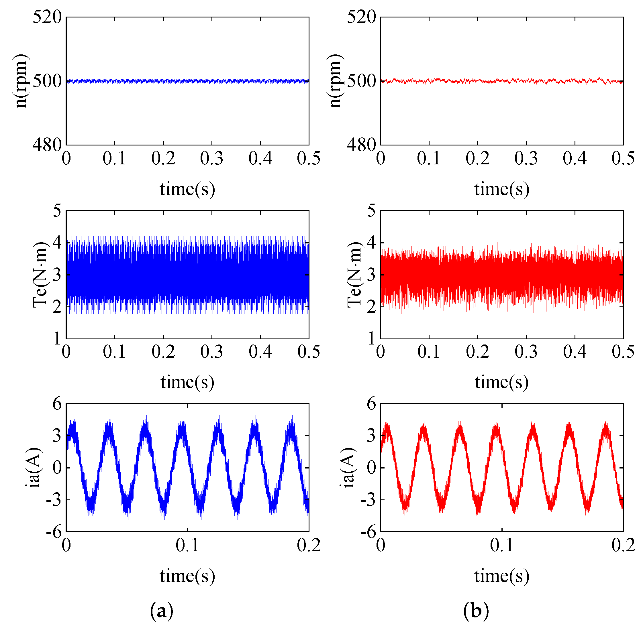
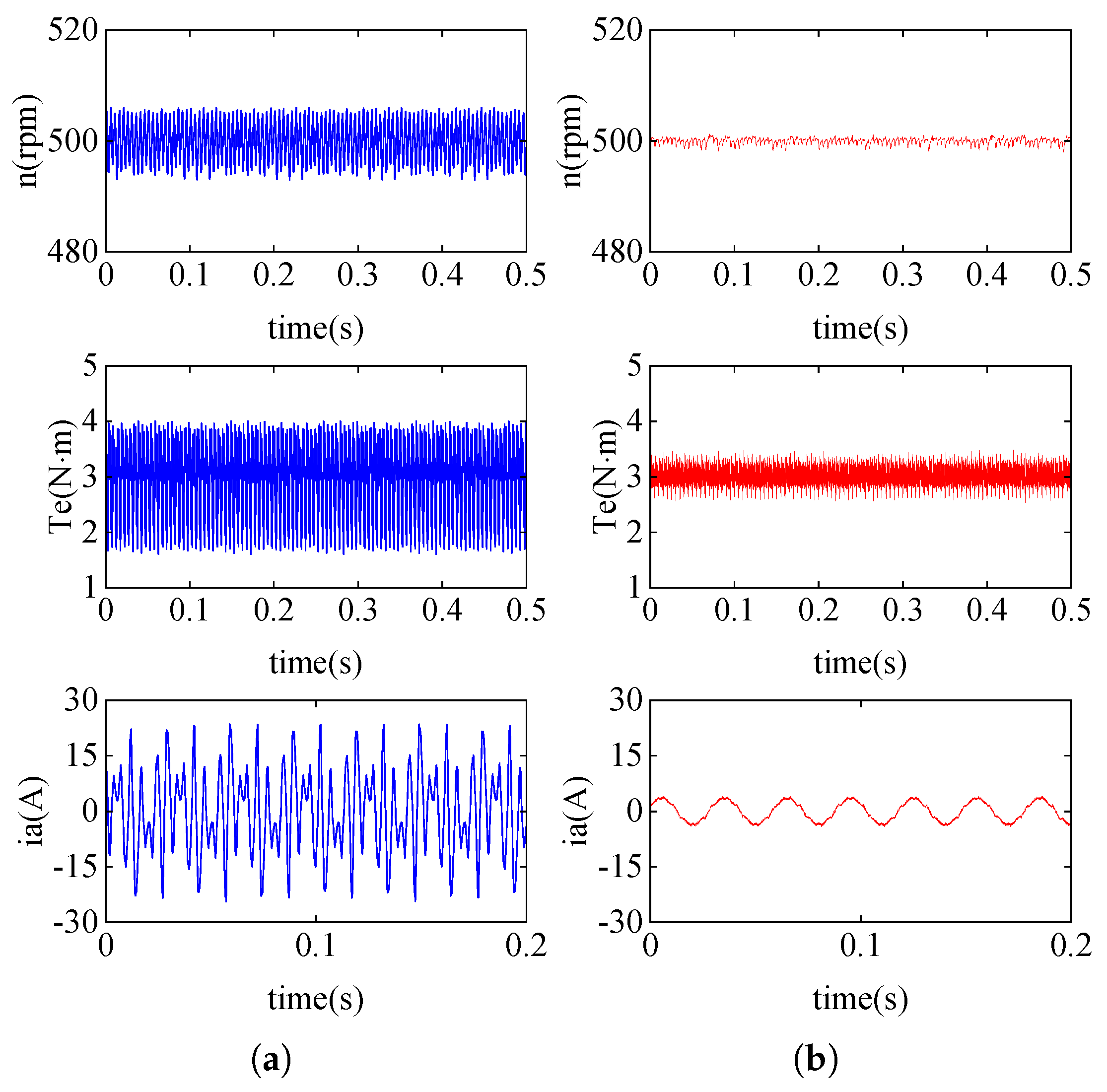
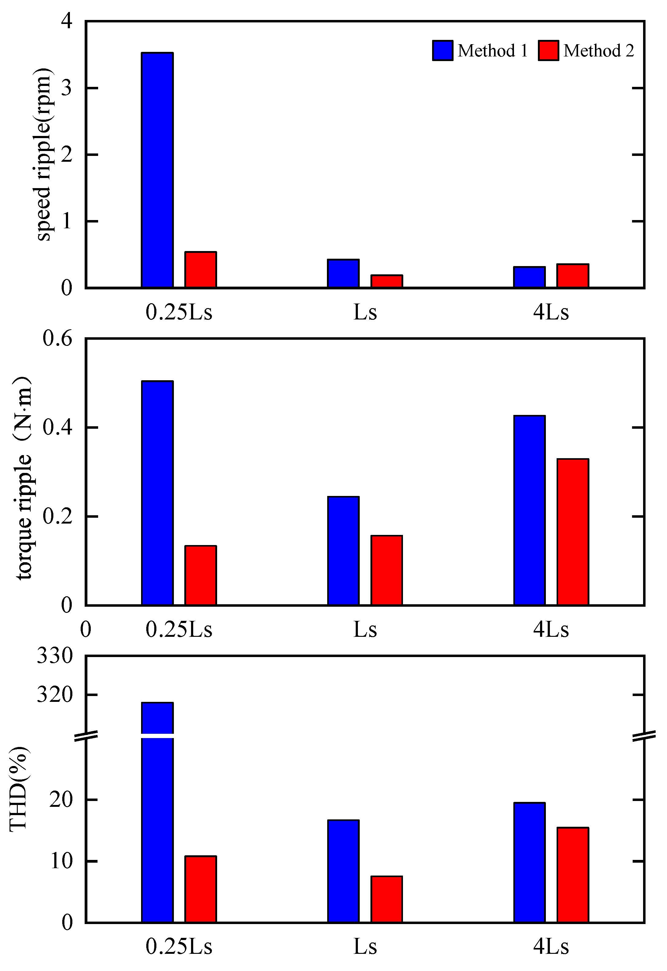
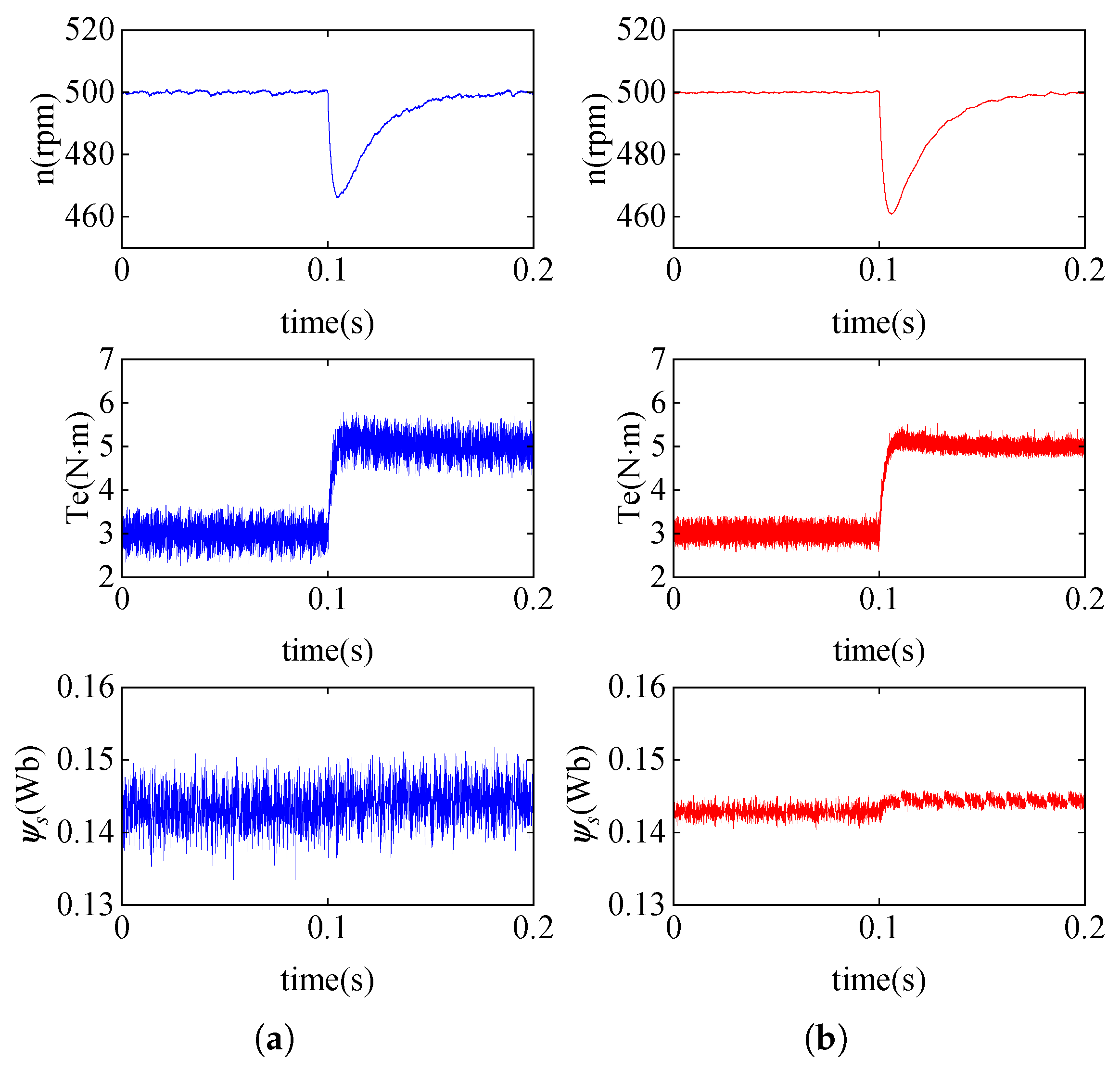
4. Simulation Results
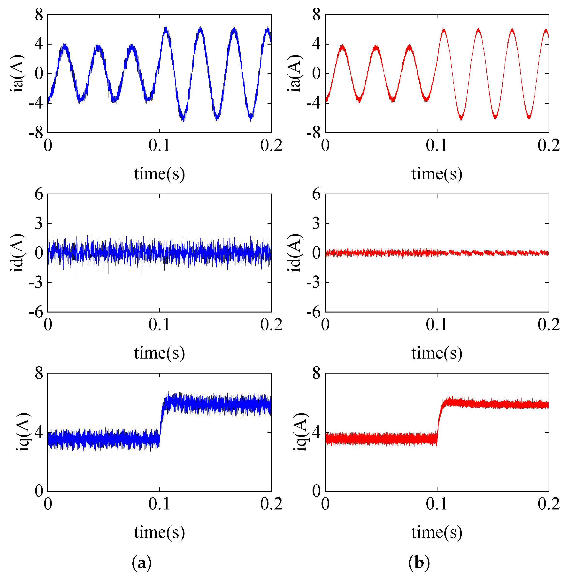
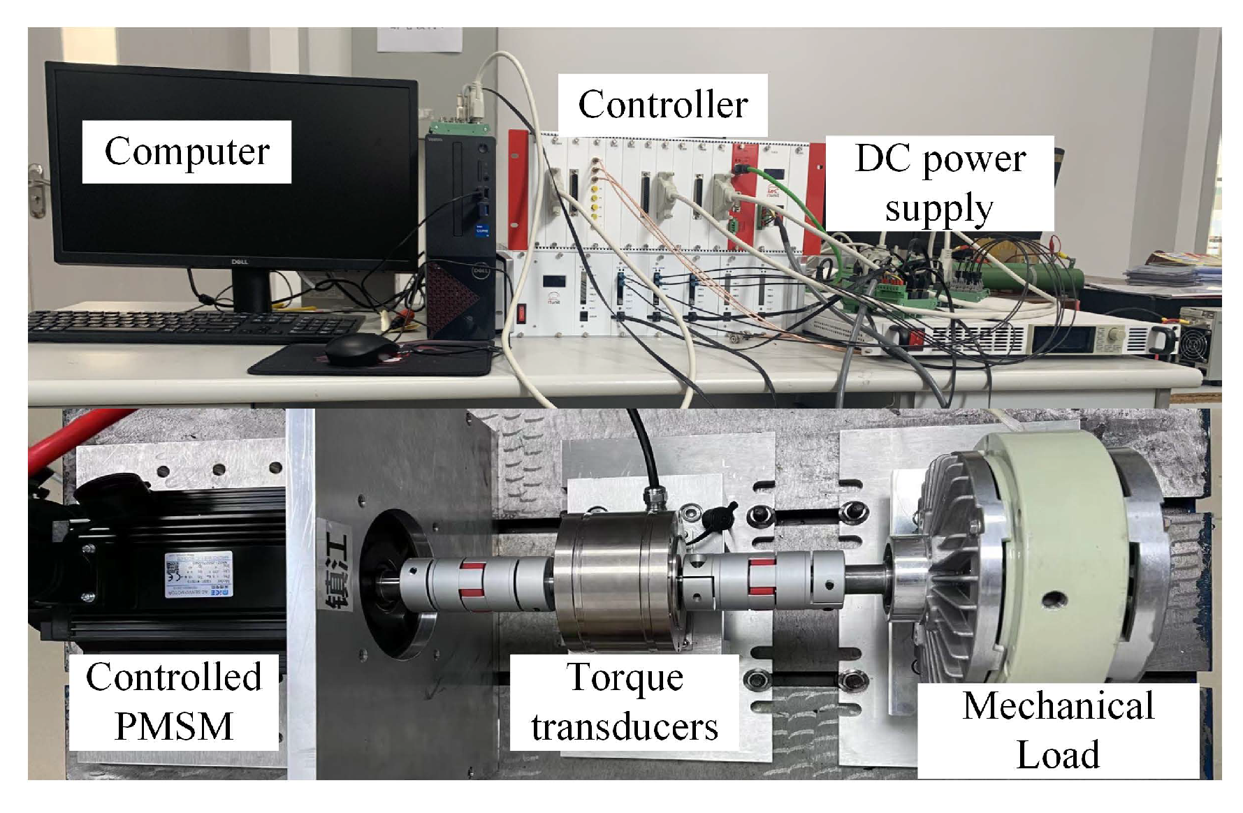
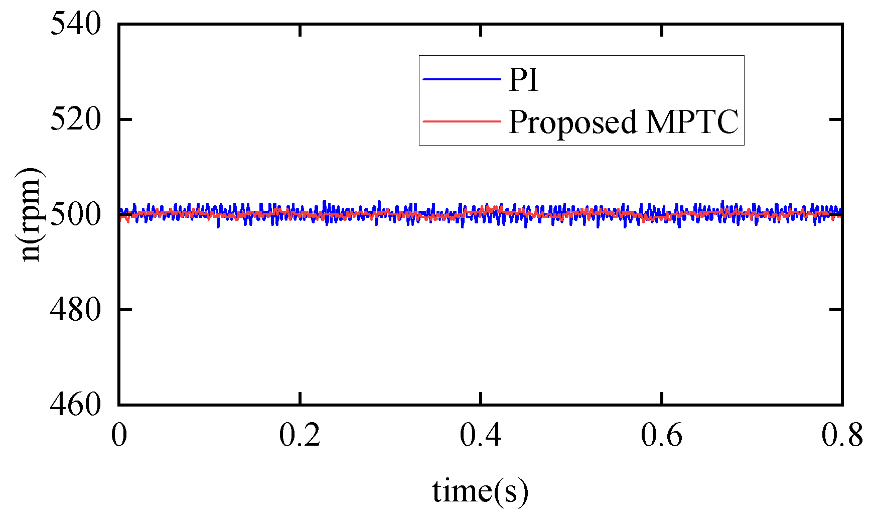
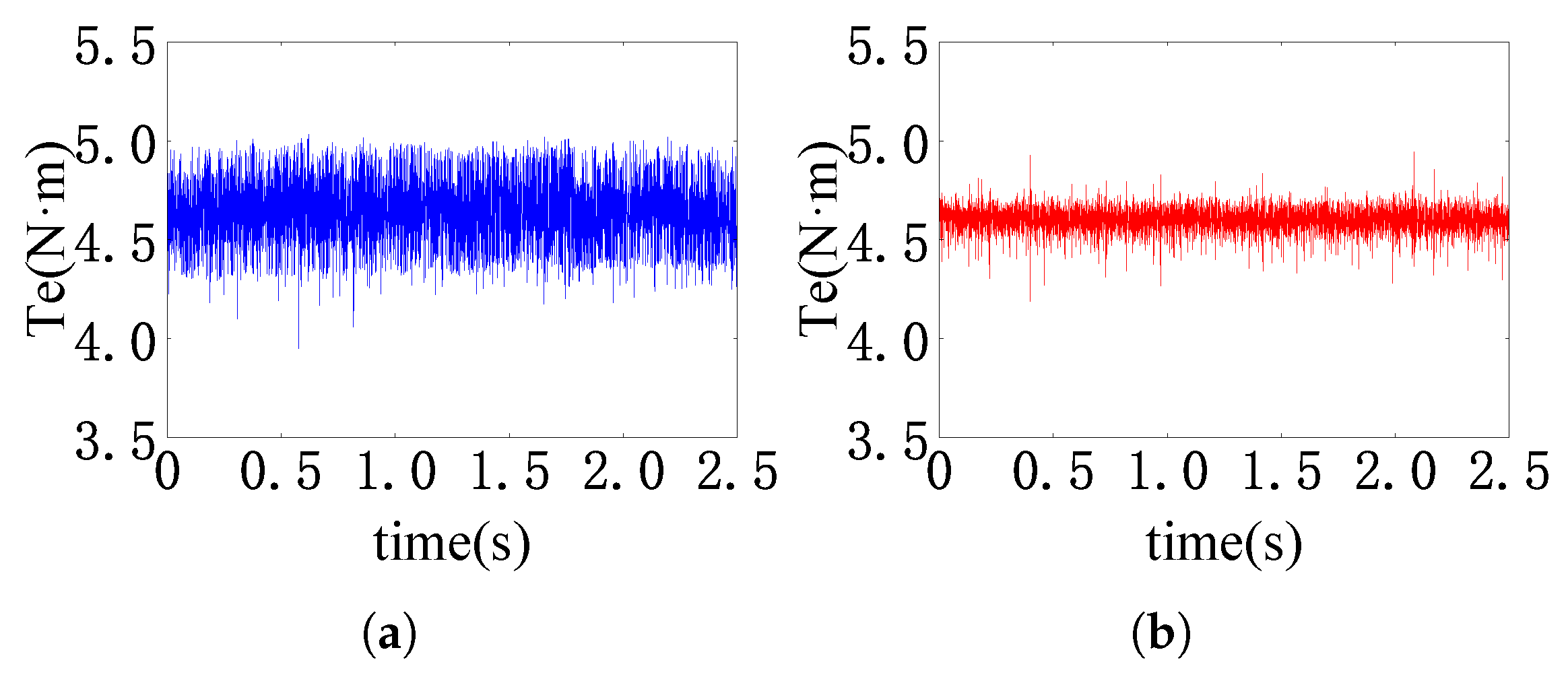
5. Experimental Results
6. Conclusions
Author Contributions
Funding
Data Availability Statement
Conflicts of Interest
References
- Hou, Q.; Ding, S.; Yu, X. Composite super-twisting sliding mode control design for PMSM speed regulation problem based on a novel disturbance observer. IEEE Trans. Energy Convers. 2021, 36, 2591–2599. [Google Scholar] [CrossRef]
- Xue, Y.; Meng, D.; Yin, S.; Han, W.; Yan, X.; Shu, Z.; Diao, L. Vector-based model predictive hysteresis current control for asynchronous motor. IEEE Trans. Ind. Electron. 2019, 66, 8703–8712. [Google Scholar] [CrossRef]
- Luo, Y.; Niu, S. Predictive current control for six-phase PMSM motor with multi-step synthesis based virtual vectors. IEEE Trans. Energy Convers. 2023, 38, 134–146. [Google Scholar] [CrossRef]
- Teng, Q.; Xu, R.; Han, X. Integral sliding mode-based model predictive current control with low computational amount for three-level neutral-point-clamped inverter-fed PMSM drives. IEEE Trans. Energy Convers. 2020, 35, 2249–2260. [Google Scholar] [CrossRef]
- Andersson, A.; Thiringer, T. Assessment of an improved finite control set model predictive current controller for automotive propulsion applications. IEEE Trans. Ind. Electron. 2020, 67, 91–100. [Google Scholar] [CrossRef]
- Zhang, X.; Yan, K. Four-segment-mode model predictive control for PMSM drives with fixed switching frequency. IEEE Trans. Transp. Electrif. 2020, 9, 452–462. [Google Scholar] [CrossRef]
- Gao, F.; Yin, Z.; Li, L.; Li, T.; Liu, J. Gaussian noise suppression in deadbeat predictive current control of permanent magnet synchronous motors based on augmented fading kalman filter. IEEE Trans. Energy Convers. 2023, 38, 1410–1420. [Google Scholar] [CrossRef]
- Gonzalez-Prieto, A.; Martin, C.; Gonzalez-Prieto, I.; Duran, M.J.; Carrillo-Rios, J.; Jose Aciego, J. Hybrid multivector FCS-MPC for six-phase electric drives. IEEE Trans. Power Electron. 2022, 37, 8988–8999. [Google Scholar] [CrossRef]
- Rodriguez, J.; Garcia, C.; Mora, A.; Davari, S.A.; Rodas, J.; Valencia, D.F. Latest advances of model predictive control in electrical drives-part II: Applications and benchmarking with classical control methods. IEEE Trans. Power Electron. 2021, 37, 5047–5061. [Google Scholar] [CrossRef]
- Belda, K.; Vošmik, D. Explicit generalized predictive control of speed and position of PMSM drives. IEEE Trans. Ind. Electron. 2016, 63, 3889–3896. [Google Scholar] [CrossRef]
- Ke, D.; Wang, F.; He, L.; Li, Z. Predictive current control for PMSM systems using extended sliding mode observer with Hurwitz-based power reaching law. IEEE Trans. Power Electron. 2020, 36, 7223–7232. [Google Scholar] [CrossRef]
- Siami, M.; Khaburi, D.A.; Rodriguez, J. Torque ripple reduction of predictive torque control for PMSM drives with parameter mismatch. IEEE Trans. Power Electron. 2016, 32, 7160–7168. [Google Scholar] [CrossRef]
- Rodriguez, J.; Garcia, C.; Mora, A.; Flores-Bahamonde, F.; Acuna, P.; Novak, M. Latest advances of model predictive control in electrical drives-part I: Basic concepts and advanced strategies. IEEE Trans. Power Electron. 2022, 37, 3927–3942. [Google Scholar] [CrossRef]
- Forbes, M.G.; Patwardhan, R.S.; Hamadah, H.; Gopaluni, R.B. Model predictive control in industry: Challenges and opportunities. IFAC-PapersOnLine 2015, 48, 531–538. [Google Scholar] [CrossRef]
- Cortés, P.; Kouro, S.; La Rocca, B.; Vargas, R.; Rodriguez, J.; Leon, J.I. Guidelines for weighting factors design in model predictive control of power converters and drives. In Proceedings of the 2009 IEEE International Conference on Industrial Technology, Churchill, VIC, Australia, 10–13 February 2009; pp. 1–7. [Google Scholar]
- Guazzelli, P.R.U.; De Andrade Pereira, W.C.; De Oliveira, C.M.R.; De Castro, A.G.; De Aguiar, M.L. Weighting factors optimization of predictive torque control of induction motor by multiobjective genetic algorithm. IEEE Trans. Power Electron. 2019, 34, 6628–6638. [Google Scholar] [CrossRef]
- Zhu, Y.; Yin, J.; Xu, G. A comparative study of MPCC and MPTC in PMSM drive system. In Proceedings of the 2018 IEEE 2nd International Conference on Circuits, System and Simulation (ICCSS), Guangzhou, China, 14–16 July 2018; pp. 36–40. [Google Scholar]
- Chen, L.; Xu, H.; Sun, X.; Cai, Y. Three-vector-based model predictive torque control for a permanent magnet synchronous motor of EVs. IEEE Trans. Transp. Electrif. 2021, 7, 1454–1465. [Google Scholar] [CrossRef]
- Li, X.; Xue, Z.; Zhang, L.; Hua, W. A low-complexity three-vector-based model predictive torque control for SPMSM. IEEE Trans. Power Electron. 2021, 36, 13002–13012. [Google Scholar] [CrossRef]
- Li, C.; Shi, T.; Yan, Y.; Zhou, Z.; Xia, C. Predictive control with optimal vector sequence for permanent magnet synchronous motors. J. Power Electron. 2020, 20, 553–565. [Google Scholar] [CrossRef]
- Yang, W.; Ding, S.; Ding, C. Fast supertwisting sliding mode control with antipeaking extended state observer for path-tracking of unmanned agricultural vehicles. IEEE Trans. Ind. Electron. 2024, 71, 12973–12982. [Google Scholar] [CrossRef]
- Ding, C.; Ding, S.; Wei, X.; Ji, X.; Sun, J.; Mei, K. Disturbance-observer-based barrier function adaptive sliding mode control for path tracking of autonomous agricultural vehicles with matched-mismatched disturbances. IEEE Trans. Transp. Electrif. 2024, 10, 6748–6760. [Google Scholar] [CrossRef]
- Sun, J.; Wang, Z.; Ding, S.; Xia, J.; Xing, G. Adaptive disturbance observer-based fixed time nonsingular terminal sliding mode control for path-tracking of unmanned agricultural tractors. Biosyst. Eng. 2024, 246, 96–109. [Google Scholar] [CrossRef]
- Sun, J.; Li, Q.; Ding, S.; Xing, G.; Chen, L. Fixed-time generalized super-twisting control for path tracking of autonomous agricultural vehicles considering wheel slipping. Comput. Electron. Agric. 2023, 213, 108231. [Google Scholar] [CrossRef]
- Dou, W.; Ding, S.; Yu, X. Event-triggered second-order sliding-mode control of uncertain nonlinear systems. IEEE Trans. Syst. Man Cybern. Syst. 2023, 53, 7269–7279. [Google Scholar] [CrossRef]
- Dou, W.; Ding, S.; Park, J.H. Practical event-triggered finite-time second-order sliding mode controller design. IEEE Trans. Cybern. 2024, 54, 1972–1983. [Google Scholar] [CrossRef]
- Dou, W.; Ding, S.; Park, J.H.; Mei, K. An adaptive generalized super-twisting algorithm via event-triggered control. IEEE Trans. Autom. Sci. Eng. 2025, 22, 393–406. [Google Scholar] [CrossRef]
- Ding, S.; Hou, Q.; Wang, H. Disturbance-observer-based second-order sliding mode controller for speed control of PMSM drives. IEEE Trans. Energy Convers. 2023, 38, 100–110. [Google Scholar] [CrossRef]
- Repecho, V.; Biel, D.; Arias, A. Fixed switching period discrete-time sliding mode current control of a PMSM. IEEE Trans. Ind. Electron. 2017, 65, 2039–2048. [Google Scholar] [CrossRef]
- Kali, Y.; Saad, M.; Doval-Gandoy, J.; Rodas, J.; Benjelloun, K. Discrete sliding mode control based on exponential reaching law and time delay estimation for an asymmetrical six-phase induction machine drive. IET Electr. Power Appl. 2019, 13, 1660–1671. [Google Scholar] [CrossRef]
- Zhao, Y.; Liu, X.; Yu, H.; Yu, J. Model-free adaptive discrete-time integral terminal sliding mode control for PMSM drive system with disturbance observer. IET Electr. Power Appl. 2020, 14, 1756–1765. [Google Scholar] [CrossRef]
- Chen, C.C.; Chen, G.S.; Sun, Z.Y. Finite-time stabilization via output feedback for high-order planar systems subjected to an asymmetric output constraint. Nonlinear Dyn. 2021, 104, 2347–2361. [Google Scholar] [CrossRef]
- Li, Y.; Xu, L.; Lv, L.; Shi, Y.; Yu, X. Study on modeling method of a multi-parameter control system for threshing and cleaning devices in the grain combine harvester. Agriculture 2022, 12, 1483. [Google Scholar] [CrossRef]
- Ji, W.; Zhang, T.; Xu, B.; He, G. Apple recognition and picking sequence planning for harvesting robot in a complex environment. J. Agric. Eng. 2024, 55. [Google Scholar]
- Zhang, H.; Ji, W.; Xu, B.; Yu, X. Optimizing Contact Force on an Apple Picking Robot End-Effector. Agriculture 2024, 14, 996. [Google Scholar] [CrossRef]
- Chen, C.; Liu, X.; Liu, C.; Pan, Q. Development of the precision feeding system for sows via a rule-based expert system. Int. J. Agric. Biol. Eng. 2023, 16, 187–198. [Google Scholar] [CrossRef]
- Dai, D.; Chen, D.; Wang, S.; Li, S.; Mao, X.; Zhang, B.; Wang, Z.; Ma, Z. Compilation and Extrapolation of Load Spectrum of Tractor Ground Vibration Load Based on CEEMDAN-POT Model. Agriculture 2023, 13, 125. [Google Scholar] [CrossRef]
- Ji, W.; Pan, Y.; Xu, B.; Wang, J. A real-time apple targets detection method for picking robot based on ShufflenetV2-YOLOX. Agriculture 2022, 12, 856. [Google Scholar] [CrossRef]
- Ji, W.; Gao, X.; Xu, B.; Pan, Y.; Zhang, Z.; Zhao, D. Apple target recognition method in complex environment based on improved YOLOv4. J. Food Process. Eng. 2021, 44, e13866. [Google Scholar] [CrossRef]
- Deng, J.; Zhao, X.; Luo, W.; Bai, X.; Xu, L.; Jiang, H. Microwave detection technique combined with deep learning algorithm facilitates quantitative analysis of heavy metal Pb residues in edible oils. J. Food Sci. 2024, 89, 6005–6015. [Google Scholar] [CrossRef]
- Wu, X.; Wang, Y.; Wu, B.; Sun, J. Classification of Fritillaria using a portable near-infrared spectrometer and fuzzy generalized singular value decomposition. Ind. Crop. Prod. 2024, 218, 119032. [Google Scholar] [CrossRef]
- Zhao, Y.; Deng, J.; Chen, Q.; Jiang, H. Near-infrared spectroscopy based on colorimetric sensor array coupled with convolutional neural network detecting zearalenone in wheat. Food Chem. X 2024, 22, 101322. [Google Scholar] [CrossRef]
- Sun, J.; Cheng, J.; Xu, M.; Yao, K. A method for freshness detection of pork using two-dimensional correlation spectroscopy images combined with dual-branch deep learning. J. Food Compos. Anal. 2024, 129, 106144. [Google Scholar] [CrossRef]
- Sun, J.; Nirere, A.; Dusabe, K.D.; Yuhao, Z.; Adrien, G. Rapid and nondestructive watermelon (Citrullus lanatus) seed viability detection based on visible near-infrared hyperspectral imaging technology and machine learning algorithms. J. Food Sci. 2024, 89, 4403–4418. [Google Scholar] [CrossRef] [PubMed]
- Basu, K.; Prasad, J.S.S.; Narayanan, G. Minimization of torque ripple in PWM AC drives. IEEE Trans. Ind. Electron. 2009, 56, 553–558. [Google Scholar] [CrossRef]
- Deb, K.; Pratap, A.; Agarwal, S.; Meyarivan, T. A fast and elitist multiobjective genetic algorithm: NSGA-II. IEEE Trans. Evol. Comput. 2002, 6, 182–197. [Google Scholar] [CrossRef]
- Li, J.; Huang, X.; Niu, F.; You, C.; Wu, L.; Fang, Y. Prediction error analysis of finite-control-set model predictive current control for IPMSMs. Energies 2018, 11, 2051. [Google Scholar] [CrossRef]
- Zhang, X.; Wang, Z. Simple robust model predictive current control for PMSM drives without flux-linkage parameter. IEEE Trans. Ind. Electron. 2023, 70, 3515–3524. [Google Scholar] [CrossRef]
- Ma, C.; Li, H.; Yao, X.; Zhang, Z.; De Belie, F. An improved model-free predictive current control with advanced current gradient updating mechanism. IEEE Trans. Ind. Electron. 2020, 68, 11968–11979. [Google Scholar] [CrossRef]


| Sector | The Target Vectors |
|---|---|
| I | , or |
| II | , or |
| III | , or |
| IV | , or |
| V | , or |
| VI | , or |
| Sector | A | B | C | D |
|---|---|---|---|---|
| I | ||||
| II | ||||
| III | ||||
| IV | ||||
| V | ||||
| VI |
| Parameter | Value |
|---|---|
| Initial population size | 30 |
| Number of generations | 20 |
| Crossover | 0.8 |
| Pareto fraction | 0.32 |
| Selection | Tournament |
| Parameter | Description | Value |
|---|---|---|
| (kW) | Rated power | 1.5 |
| (N·m) | Rated torque | 10 |
| p | Number of poles pairs | 4 |
| () | Stator resistance | 1.5 |
| (mH) | Stator inductance | 4.37 |
| (Wb) | Rotor magnet flux linkage | 0.142 |
| J (kg·) | Rotational inertia | 0.00194 |
Disclaimer/Publisher’s Note: The statements, opinions and data contained in all publications are solely those of the individual author(s) and contributor(s) and not of MDPI and/or the editor(s). MDPI and/or the editor(s) disclaim responsibility for any injury to people or property resulting from any ideas, methods, instructions or products referred to in the content. |
© 2025 by the authors. Licensee MDPI, Basel, Switzerland. This article is an open access article distributed under the terms and conditions of the Creative Commons Attribution (CC BY) license (https://creativecommons.org/licenses/by/4.0/).
Share and Cite
Li, S.; Ma, L.; Hou, J.; Ma, Y.; Lai, R. Three-Vector-Based Smart Model Predictive Torque Control of Surface-Mounted Permanent Magnet Synchronous Motor Drives for Robotic System Based on Genetic Algorithm. Actuators 2025, 14, 149. https://doi.org/10.3390/act14030149
Li S, Ma L, Hou J, Ma Y, Lai R. Three-Vector-Based Smart Model Predictive Torque Control of Surface-Mounted Permanent Magnet Synchronous Motor Drives for Robotic System Based on Genetic Algorithm. Actuators. 2025; 14(3):149. https://doi.org/10.3390/act14030149
Chicago/Turabian StyleLi, Shenghui, Li Ma, Jingrui Hou, Yiqing Ma, and Rongbo Lai. 2025. "Three-Vector-Based Smart Model Predictive Torque Control of Surface-Mounted Permanent Magnet Synchronous Motor Drives for Robotic System Based on Genetic Algorithm" Actuators 14, no. 3: 149. https://doi.org/10.3390/act14030149
APA StyleLi, S., Ma, L., Hou, J., Ma, Y., & Lai, R. (2025). Three-Vector-Based Smart Model Predictive Torque Control of Surface-Mounted Permanent Magnet Synchronous Motor Drives for Robotic System Based on Genetic Algorithm. Actuators, 14(3), 149. https://doi.org/10.3390/act14030149