1. Introduction
The main goal of using suspension systems in vehicles is to increase the driving comfort of the passengers. These systems isolate vehicles from vibrations caused by vehicle speed and road profile. There are various studies on vibration suppression in active suspension systems (ASS) in the automotive industry [
1,
2,
3]. Information on the design of automobile suspension systems for driving comfort and the control of wheel load changes for frequencies below body structure resonances were studied in [
4]. In addition, the optimum active suspension structures for quarter-vehicle models were detailed and various suggestions made in [
5]. The first study on this topic applied the H∞ control method to a complete-vehicle model to analyze shaking and driving performance [
6]. Cherry and Jones conducted a study on the control of a suspension system using the fuzzy logic control method [
7]. El Madany and Abduljabbar studied quarter-vehicle systems in a simulation environment using the linear quadratic Gaussian (LQG) method [
8]. Another study used the genetic algorithm (GA) optimization method and a fuzzy logic controller [
9]. Yoshimura et al. [
10] applied the sliding mode control algorithm, in which the sliding surface is obtained using linear quadratic control theory, to a quarter-vehicle system in an experimental environment. They showed that the active suspension system improved performance more than the passive suspension system.
The sliding mode neural network inference fuzzy logic control (SMNNNFLC) method was proposed by Al-Holou et al. [
11]. Their results were compared with sliding mode control (SMC) and sliding mode fuzzy logic control (SMFLC) methods. Active control of the suspension system was achieved with the proportional-integral sliding mode (PISMC) and linear quadratic regulator (LQR) control methods [
12]. The methods were compared together with passive suspension. It has been shown that a more robust outcome was obtained using the PISMC method [
12]. An experimental study of the linear control of quarter-vehicle systems was conducted by Lauwerys et al. [
13]. The control of a quarter car active suspension system with fuzzy logic and proportional-integral-derivative (PID) control methods has been proposed [
14] that reduces body acceleration and increases passenger comfort using fuzzy logic control. Fateh and Alavi studied the simulation of the impedance control of an ASS system [
15]. The ASS and passive suspension systems were compared, and better performance was observed using the ASS system.
The LQR and PID control methods have been used to control the active suspension system of a quarter car model [
16]. This study showed that the displacement performance of the body can be improved using the LQR and PID control scheme. Another study was carried out on the control of the suspension system using intelligent control methods [
17]. A simulation of a quarter-vehicle system using the LQR control method was designed by Nagarkar et al. [
18]. In this study, the passive system and the LQR control method were compared, and it was observed that driving comfort increased and the LQR method was flexible. On the other hand, a quarter-vehicle suspension system using different road profiles was controlled by the LQR control method [
19]. A comprehensive review of the control of vehicle suspension systems was conducted by Aly and Salem [
20]. Multi-purpose control of active suspension systems was carried out using the adaptive backstepping control method [
21]. To increase driving comfort, this method was applied to a quarter-vehicle system in a simulation environment using the Lyapunov barrier function. The quarter-car suspension system was controlled by the PID control method, and the outcome was compared with the passive state [
22]. It was shown that driving comfort and road holding increased.
An experimental study was conducted by Tang et al. [
23]. The study was developed using a state observer-based Takagi-Sugeno fuzzy controller (SOTSFC) for a semi-active quarter-car suspension system equipped with a magnetorheological (MR) damper. The results of this method were compared to the Skyhook controller. Yu et al. [
24] carried out an experimental study on a quarter car based on a series of active variable geometry suspensions. The method achieved a success rate of up to 41% without degrading suspension deflection. Khazaie et al. [
25] carried out a study on a suspension model that prevents quarter-vehicle suspension systems from losing contact with the road. Nagarkar and his research group [
26] simulated the control of a quarter-vehicle system using PID and LQR control methods. Multi-objective optimization was performed using a genetic algorithm. It was observed that driving comfort increased.
Na et al. [
27] implemented adaptive finite-time fuzzy control of nonlinear active suspension systems with input delay. The systems were designed, and these methods were applied to a quarter-vehicle system in Carsim and MATLAB simulation environments. The results were calculated and recorded accordingly, showing promising performance. Song and Wang proposed an incremental model predictive control (MPC) method for active suspension systems using an experimental test [
28]. The results of this study were compared with two traditional control methods. Na et al. [
29] performed active suspension control of a quarter-vehicle system based on experimental tests. Unlike existing techniques, this study did not use any function methods such as neural networks (NNs) or fuzzy logic systems (FLSs). Active control of quarter and half vehicle suspension systems has been achieved using PID, PID-LQR, and LQR Fuzzy PID control methods [
30]. When these methods are compared, it is shown that the Fuzzy-PID controller reduces vibration of car body displacement, car body acceleration, and wheel deflection in the rear and front suspension systems. However, it was shown that using the Fuzzy PID control method produced an unsatisfactory ride and poor handling in the rear suspension system.
Shalabi et al. [
31] conducted an experimental study using neuro-fuzzy sound control of a quarter-vehicle system with an air spring suspension system. In this study, a pressure controller based on the FLC methods was used. The air volume was designed and simulated using ANFIS. It has been shown that increasing the total air volume led to a reduction in the transmitted acceleration to the mass. The active control of the quarter-car system was simulated using fuzzy PID and LQR control methods [
32]. Although it has been stated that both methods improve the operation of the system, using the LQR method resulted in a better performance compared to the PID method. Shafiei investigated the impact of the PID method on a quarter-vehicle model using the Ziegler–Nichols method through the control system designer application [
33].
Adaptive harmonic control of a quarter-vehicle suspension system was examined by Nichiţelea and Unguritu [
34]. The PI controller, H∞ controller, and model predictive controllers were simulated. It was observed that a better performance was obtained using the adaptive harmonic control method. The experimental verification of the control of the active suspension system in a quarter-vehicle system was studied by Huang et al. [
35]. A reliable, efficient, and simple control was presented and verified for a quarter-vehicle active suspension system equipped with an electro-hydraulic actuator. The approximation-free control (AFC) method was used in the study. The applicability, effectiveness, and generality of the AFC method were investigated for different road conditions based on the various experimental tests. The results were compared with the AFC method with back-stepping and PID controllers. It was found that using the AFC method resulted in improved performance based on all parameters, including the suspension displacements and acceleration responses with regard to the safety of the suspension system and the comfort of the passengers.
Abut and Salkim investigated the active control of a quarter-vehicle suspension system using the PSO-based fuzzy LQR control method [
36]. The graphical and numerical variations results were based on the LQR, and the PSO-based control methods were compared. Additionally, the results were compared based on the passive system and other research. It was shown that the performance of the suspension system increased compared to the passive system based on the integral time-weighted absolute error (ITAE) performance criterion. It was also observed that the suspension performance significantly increased compared to the passive system. Vehicle body movement, vehicle acceleration, suspension deflection, and tire deflection were improved by 84.2%, 90%, 84.5%, and 86.7%, respectively. It was shown that road handling and driving comfort increased compared to state-of-the-art systems. A neural network algorithm based on reinforcement learning was used to optimize the LQR controller and applied to a quarter-vehicle system [
37]. It was reported that user comfort increased by 67% and 14% compared to the passive system and the non-optimized LQR, respectively.
In this study, the active control of a quarter-vehicle suspension system was modeled using the Lagrange–Euler method. LQG and FLQG control methods were designed and used for active control to increase vehicle handling and passenger comfort. The study aims to reduce or eliminate unwanted vibrations by performing active control of passive suspension systems using the recommended methods. The optimum values of the coefficients of the points where the membership functions of the LQG and Fuzzy LQG methods touch were obtained using the grey wolf optimization (GWO) algorithm. The success of the control performance of the applied methods based on the passive suspension system was compared. The results were compared with each other and with other work based on the ITAE performance criterion and RMSE performance criteria. It was shown that using the proposed control method resulted in significant improvements compared to the passive suspension system. Car body movement, vehicle acceleration, suspension deflection, and tire deflection were improved by 88.2%, 91.5%, 88%, and 89.4%, respectively. In addition, vehicle driving comfort was significantly improved.
This study investigates active control methods that aim to reduce vibrations in vehicle suspension systems. It has been observed that conventional passive suspension systems cannot reduce vibrations effectively enough and fail to improve ride comfort. To fill this gap, LQG (linear quadratic Gaussian) and FLQG (fuzzy linear quadratic Gaussian) control methods are used for active control, and the GWO (grey wolf optimization) algorithm is applied to determine the optimum control parameters. As a result, significant performance improvements were obtained compared to the passive suspension system. The effectiveness of the active control methods has been more clearly demonstrated by comparing the passive system with existing studies in literature and significant improvements in vehicle parameters have been achieved.
The contributions of this study are as follows:
By utilizing the grey wolf optimization (GWO) algorithm, this study determines the optimal weights of the points where the membership functions of the fuzzy LQG control method intersect. The application of this control method to the active suspension system enables the quarter-car suspension to make its own decisions to optimally determine the critical Q and R parameters in system control.
The second contribution is the comparison of the LQG and fuzzy LQG control methods with each other and the comparison of their results with the those of passive suspension system.
The third contribution is enabling the comparison of the effectiveness of the control methods using performance indices, both relative to each other and to other existing research in the field.
The main contribution of this study is to combine the self-determination capability of the fuzzy logic control method with the advantages of the LQG control method, which is one of the optimal control methods, and to introduce it into the literature on the control of ASSs.
The rest of the paper is organized as follows:
Section 2 presents the modeling of the suspension system.
Section 3 describes the design of the LQG, Kalman filter, and GWO-based fuzzy LQG control methods. The results of the methods used are presented, compared, and discussed in
Section 4. Concluding remarks and future directions are provided in
Section 5.
3. System Controller Designs
The purpose of the controller designs is to increase vehicle handling and passenger comfort. It aims to reduce vibrations and design a robust system using the recommended control methods in active suspension systems. The main goal is to obtain minimal error values by increasing vehicle handling and passenger comfort. The linear quadratic Gaussian (LQG) and the fuzzy LQG methods were used to control the quarter-vehicle suspension system. These methods are detailed as follows: The LQG control method is one of the optimal control methods. It is a method where the LQR and a Kalman filter are used together [
38,
39]. Thus, information will first be given about the LQR control method. The most important problem of optimal control methods is to determine the optimal control law that minimizes the performance index, which is determined under various economic and safety constraints.
The LQR control method is a control method based on the state-space model of the system [
40,
41]. The main goal of this method is to obtain the control signals that cause physical constraints or lead to an excessive (maximizing or minimizing) performance criterion or cost function. The system is controlled with the LQR control method, the input is
, and
K and
u indicate the feedback control input and the states of the system, respectively. The state-space equations are used to select a control input to minimize the cost function.
The control system aims to minimize the integral of the quadratic performance index.
and
are weight matrices,
is a positive semi-definite symmetric matrix, and
is a positive definite matrix (
). The control vector is represented by
u and
x shows the states of the system. Equation (11) is a quadratic concerning both
and
The optimum feedback input (
K) is calculated using Equation (12).
B and
represent the input matrix and positive definite, respectively, and the value of the
P matrix was obtained using the Riccati equation.
A represents the state matrix.
The LQG control method is beneficial as it solves the disadvantage of the LQR control method (requires sensors for each situation) by replacing it with an observer Kalman filter [
42,
43]. This eliminates the deficiency that arises due to the inability to measure all states of the system and is very useful as it reduces the cost. However, it does not guarantee the system’s robustness against uncertainties in environmental conditions. The Kalman filter is used to estimate the system’s state based on the system output. It estimates the states of the systems from the input and output information of the systems and can optimally filter measurement and process noises with known covariances of the noises [
44,
45,
46]. This filter is used to minimize the covariance matrix of the error due to the Gaussian measurement or process noise.
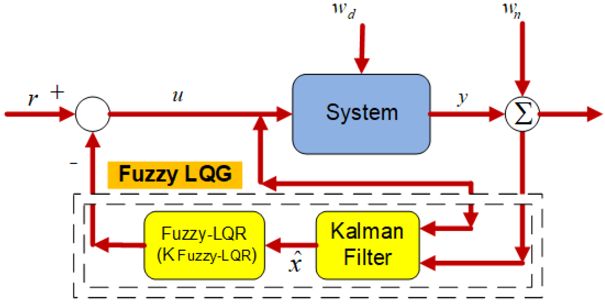
Figure 2 shows the block diagram of the linear quadratic Gaussian (LQG) control method.
In this diagram,
represents the process noise given to the random system, and
represents the measurement noise. Using known inputs
u and measurement
y, a Kalman filter is used to estimate the state vector and output vector. The equations of the Kalman estimator are given below (from (16) to (18)):
where
is the predicted x value,
must be positive definite,
must be positive semidefinite, and the system must be observable. Process noise is expressed as
w~N(0,
Q) and measurement noise as
v~N(0,
Q).
is the input covariance matrix and
is the output covariance matrix. The algebraic constant
P, which minimizes the cost function, is obtained from the Ricatti equation. The filter constant (
L) was calculated using the Ricatti equation and the below equation:
LQG controllers can be used in both linear time-invariant and linear time-varying systems. This control method has many uses since it can also be applied to nonlinear systems [
46].
Fuzzy LQR control is a method in which the advantageous aspects of the LQR and fuzzy control methods are used together [
46,
47]. The matrices containing the
Q and
R parameters, which are of critical importance in the LQR control method, are obtained by the fuzzy logic method. This leads the LQR method to have a dynamic structure. This increases the performance of the method (fuzzy LQR) due to changing conditions. The fuzzy LQR controller calculates
K = [
k1,
k2,
k3] state feedback gain values by applying the rules of the fuzzy logic controller, which uses the error and its derivative as input. The boundary values of the membership functions are calculated with the grey wolf optimization (GWO) algorithm [
48,
49], which is one of the herd-based optimization algorithms.
The grey wolf optimization (GWO) algorithm is a contemporary herd-based meta-heuristic optimization technique that is widely used in various studies. Herd-based methods are preferred due to their ability to provide global optimum solutions, as well as their speed, simplicity, and deterministic nature. The GWO algorithm was first proposed by Mirjalilli et al. [
48]. It has gained popularity because of its efficiency in finding global optimum solutions, offering superior performance compared to other optimization techniques [
48,
49]. This success is particularly evident in solving various problems found in the literature. The core idea behind the GWO algorithm is inspired by the social structure and hunting strategies of grey wolves in the wild. Grey wolves employ three fundamental hunting behaviors: encircling, hunting, and attacking prey. Additionally, they have a hierarchical social structure divided into four main classes: Alpha (α), Beta (β), Delta (δ), and Omega (ω).
Alpha (α) wolves: These are the leaders of the pack, positioned at the top of the hierarchy. They make all major decisions regarding the pack’s activities, including when to sleep and walk, and how to manage the hunting process. Their role is crucial in maintaining order and discipline within the pack.
Beta (β) wolves: Positioned below the Alpha wolves, Betas are the second-in-command and serve as the main support for the Alpha in decision-making processes. They help guide the pack and often assist with leadership tasks.
Delta (δ) wolves: Delta wolves are situated in the third tier of the pyramid. Their responsibilities include ensuring the pack’s survival, maintaining the pack’s social balance, and securing the food supply.
Omega (ω) wolves: The lowest-ranking wolves in the hierarchy, Omega wolves must follow the orders of the higher classes. They are typically tasked with supporting the pack in catching prey.
The GWO algorithm’s ability to find global optima stems from its powerful search capability, which is modeled on the hunting behaviors of grey wolves. The algorithm starts with random search and calculates the suitability value of each wolf based on the cost function. In the process of generating candidate solutions, the best solutions are structured according to the hierarchical order, from Alpha at the top to Omega at the bottom. Mirjalilli et al. [
48] defined the encircling behavior of the wolves with the following equations:
In this context,
t represents the instantaneous iteration, while
A and
C are coefficient vectors.
denotes the position vector of the prey, and
represents the position vector of a grey wolf. The coefficient vectors
A and
C are calculated using the Equations (24) and (25).
In this algorithm,
and
are random vectors within the range [0, 1]. The parameter α represents a coefficient that decreases linearly from 2 to 0 throughout the iterations. The top three solutions obtained during the search process are recorded, and the positions of the other wolves are updated based on the positions of the best search agents. These top three solutions are assigned to the Alpha (
α), Beta (
β), and Delta (
δ) wolves, respectively. The Omega (
ω) wolves must update their positions according to these top three wolves.
and represent the positions of the Alpha, Beta, and Delta wolves, respectively. X denotes the current position of a wolf, while indicates the updated position of the prey. The top three wolves are continually updated with each iteration. , and are randomly generated vectors, and , and represent the calculated coefficient vectors. In summary, the GWO algorithm primarily searches based on the locations of the Alpha, Beta, and Delta wolves. These wolves separate to search for prey, but they converge when attacking the prey. To mathematically model this behavior, the A parameter is assigned random values greater than 1 or less than 1. This variability supports the exploration process, which is key for the global search capabilities of the GWO algorithm.
Step 1: First, start the wolf population ( and enter the parameters , and .
Step 2: Calculate the appropriate position of each wolf in the population and select the three wolves with the best positions in them as , and .
Step 3: Update the positions of other wolves in the pack (Equations (25)–(31)).
Step 4: Update , and parameters (Equations (24) and (25)).
Step 5: Calculate the appropriateness of the positions of all wolves in the pack.
Step 6: Update the positions of and (alpha, beta, and delta) wolves.
Step 7: When the maximum number of iterations is reached, the global optimum position is obtained. Otherwise, step 2 should be repeated to update the parameters.
Mean square error (MSE) was used as the objective function to minimize error values (for the GWO algorithm). The Mamdani method and triangle-type membership functions were used. The flowchart steps of the GWO algorithm applied to the fuzzy LQG control method are given below.
Steps of the Flowchart:
Step 1. Define the Fuzzy LQG Model: First, create the overall design of the fuzzy logic controller and the LQG control structure. This determines the basic structure of the controlled system.
Step 2. Define Membership Functions: Determine the linguistic terms to be used in the system (e.g., “low”, “medium”, “high”) and create the membership functions. These functions define the classifications in which the control inputs will be evaluated.
Step 3. Start Grey Wolf Optimization Algorithm: Initialize the population (wolves) of the GWO algorithm. Each wolf represents a combination of membership functions.
Step 4. Define Fitness Function: Define the fitness function for the GWO algorithm. This function measures the performance of the control system (e.g., minimizing the sum of error squares).
Step 5. Calculate Fitness Values: Test the solution of each wolf and calculate the fitness function. This shows how good each solution (coefficient) is.
Step 6. Find the Best Solution: Identify the Alpha (best) wolf and the helper wolves (Beta, Delta). These wolves are the leaders that will lead to the better solution.
Step 7. Update Pack Movement: The wolves move through the solution space, guided by the leaders. They follow the pack behavior when updating their position (coefficients).
Step 8. Check Iterations: Repeat the steps until the set maximum number of iterations is reached. During iterations, the wolves’ solutions improve.
Step 9. Determine the Optimal Coefficients: At the end of the iterations, determine the best solution (optimal coefficients).
Step 10. Use the Optimal Coefficients in the Fuzzy LQG Model: Apply the optimal membership function coefficients obtained with the GWO algorithm to the fuzzy LQG control system.
Step 11. Evaluate the Results: Evaluate the performance of the system. Observe how successful the control system is. If the performance is insufficient, you can adjust the model and repeat the process.
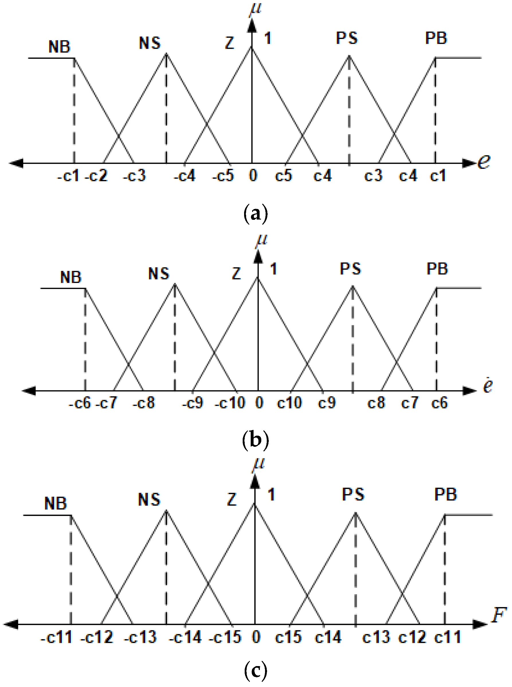
Mean square error (MSE) was used as the objective function to minimize error values (for the GWO algorithm). The Mamdani method and triangle-type membership functions were used. Membership functions (
,
ve F) and the rule table for the fuzzy LQR method are shown below in
Figure 3,
Table 1 and
Table 2. For the GWO algorithm, the population of wolves was selected as 40 and the maximum number of iterations was selected as 30. It was observed that the optimum values were obtained.
The limit values and rule table of membership functions in the fuzzy LQR method are shown in
Table 1 and
Table 2. The variables of the FLQR method,
, indicate error, error change, and strength, respectively. NB, NS, Z, PS, and PB represent negative big, negative small, zero, positive small, and positive big, respectively, as shown in
Table 2.
Figure 4 shows the block diagram of the fuzzy LQG control method.
4. Simulation Results and Discussion
The control algorithms based on fuzzy LQG methods using LQG and GWO were designed and implemented for a quarter car suspension system. The results were calculated accordingly, and the variations were saved in tables and graphs, as will be detailed in this section. The main purpose of controlling the vehicle suspension system is to minimize the disruptive effects caused by road entry that affect passenger comfort.
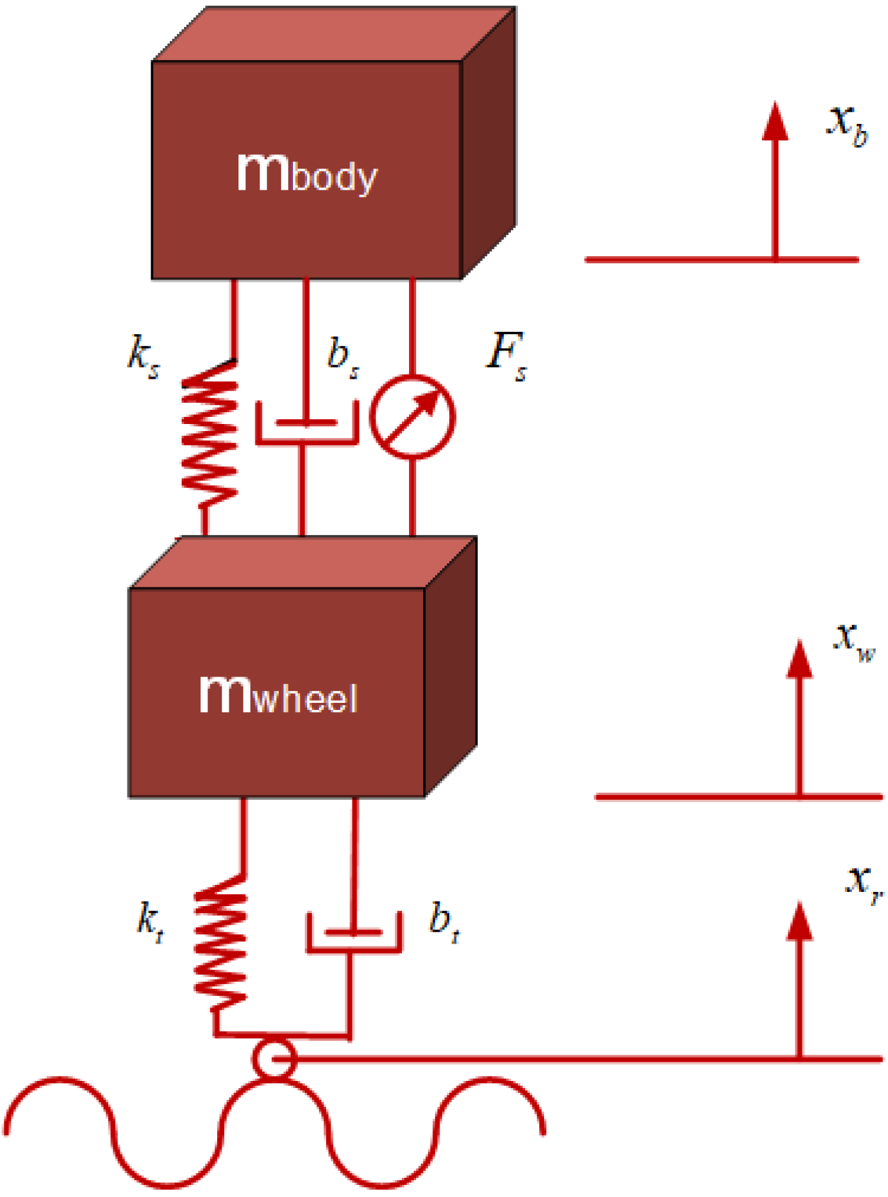
The physical parameters of the quarter-vehicle suspension system are
= 300 kg,
= 60 kg,
= 16,000 N/m,
= 1000 Ns/m,
= 190,000 N/m, and
= 1000 Ns/m. The initial value of the position of the vehicle suspension system is x = 0 m. The system simulation time was 2.5 s. The road entrance is a mound, and it is about 5 cm high, as shown in
Figure 5.
The results for the fuzzy LQG based on LQG and GWO for passive and active control of the suspension system are shown in
Figure 6. The vehicle’s body motion and body acceleration are the factors that influence passenger comfort. The impact of these parameters based on the passive state is shown in
Figure 6 and
Figure 7. These results were obtained based on fuzzy LQG control methods using LQG and GWO.
The results of the vertical displacement movement of the vehicle body, displayed in
Figure 6, show that the vibration amplitude and settling time are significantly reduced based on all control methods compared to the passive suspension system. Relatively lower vibration amplitude values are obtained when the fuzzy LQG method based on GWO is used (between 0.016~0 m) compared to the LQG (0.029~0.001 m) method. As shown in
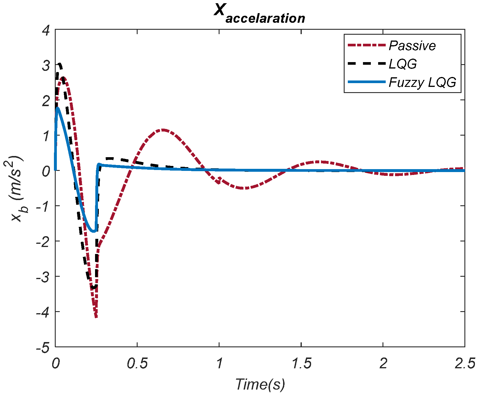
Figure 7, the performance of damping the acceleration amplitudes is relatively better when the fuzzy LQG control type based on GWO is used compared to the LQG method. While the range of the acceleration is ±1.75
for the fuzzy LQG control type based on GWO, this is about (3~(−3.2) m) for the LQG method. The results for the suspension deflection and tire deflection based on the applied control methods are shown in
Figure 8 and
Figure 9, respectively.
This shows that the fuzzy LQG control method is more effective in reducing vibrations, resulting in less oscillation and greater system stability. These results help assess how effectively the applied control methods manage the deflections in both the suspension and tires. Proper deflection control is crucial for maintaining the vehicle’s stability and handling, as excessive deflections can lead to discomfort or reduced control over the vehicle, especially in challenging driving conditions.
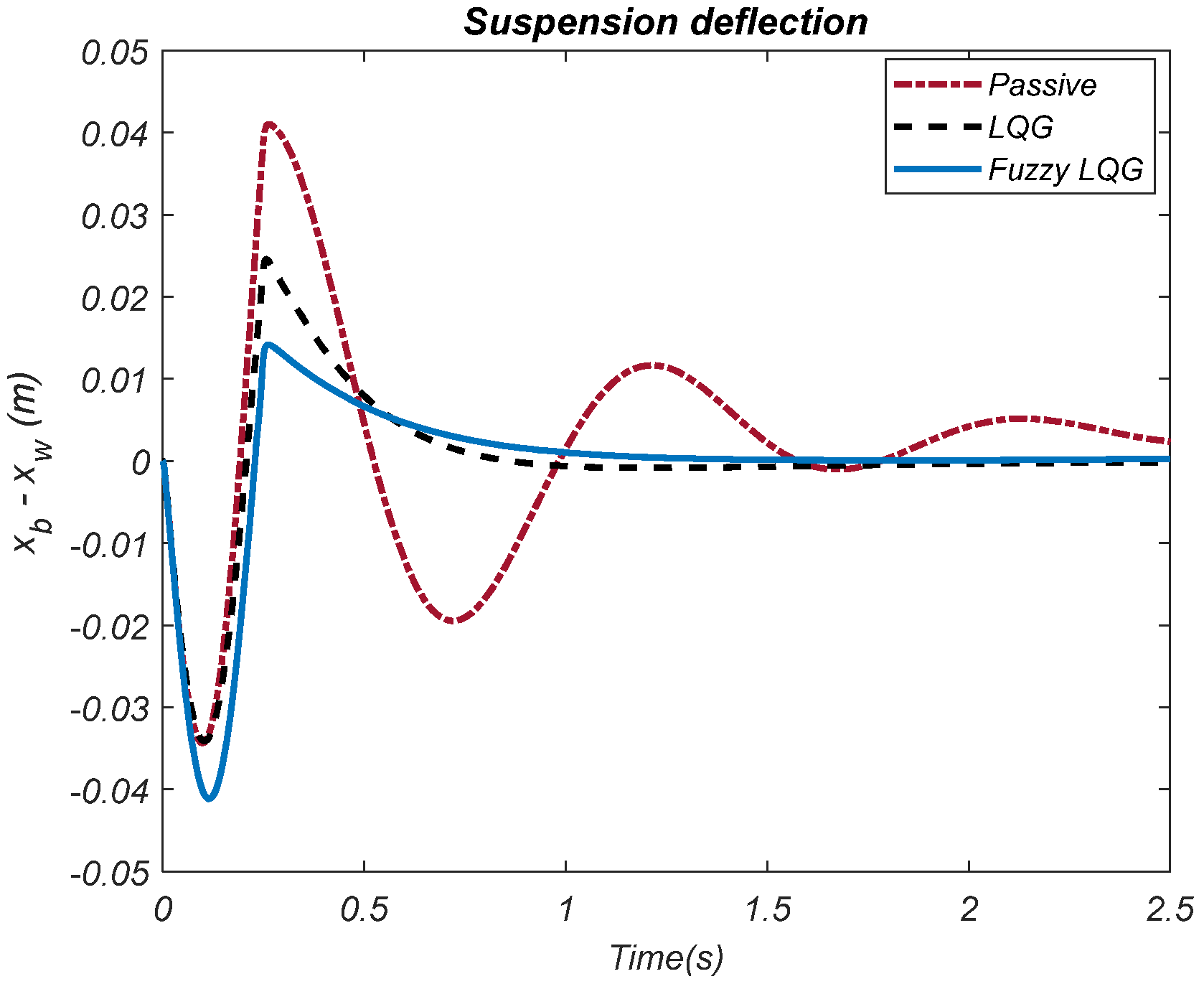
The results of the suspension contraction in
Figure 8 show that the contraction amplitudes of the fuzzy LQG control type based on GWO are lower than the LQG control method. The contraction amplitude varies between 0.014~0 m for the fuzzy LQG control type based on GWO. This range for the LQG method is about 0.024~0 m. It is shown in
Figure 9 that the tire deflection amplitude is relatively lower for the fuzzy LQG control type based on GWO compared to the LQG control method. The tire deflection amplitude ranges for the fuzzy LQG control type based on GWO is about −0.0011~0.0015 m. This range is approximately −0.001~0.0021 m for the LQG control method. The force graph used in active control is shown in
Figure 10.
The low amount of force used by a controller to reduce vibrations makes the method advantageous. The change in force is shown in
Figure 10. It is shown that the variation in the force is approximately within the range of −490~205 N based on the GWO-based fuzzy LQG control method. This variation is approximately −556~352 N when the LQG control type was used. Overall, the fuzzy LQG type controller provides better control with less force when all the results in the figures are considered.
The parameters of vehicle body motion, vehicle acceleration, suspension deflection, tire deflection, and the force required to be applied were calculated using (33) for the methods used in this study, as shown in
Table 3. The results were compared using the ITAE performance index. Similarly, the methods were compared using the RMSE criterion given in Equation (34), and the results are given in
Table 4.
The car body motion’s lowest error based on the ITAE performance criteria is highlighted in bold in
Table 3. The lowest error was obtained using the fuzzy LQG method compared to the LQG control method. The error rate is about 0.0023 m for the fuzzy LQG method and about 0.0039 m for the LQG method. When the acceleration error results are compared based on the used control methods, as shown in
Table 3, the lowest value is recorded for the fuzzy LQG when using the GWO control method compared to the LQG method. While the acceleration error is about 0.0604 m/s
2 for the fuzzy LQG using GWO, it is 0.1355 m/s
2 when using the LQG method.
According to the suspension clearance error results, the lowest error performance was obtained using the GWO-based fuzzy LQG method with 0.0022 m, while this value is 0.0039 m for the LQG method. In addition, the results for the tire deviation error show that using the GWO-based fuzzy LQG method resulted in a lower error of about 0.00012 m. It is shown that the tire deviation error is about 0.00026 when the LQG method is used. When the force errors are compared using control methods, it is shown that the lowest force error value of 55.27 N is obtained using the GWO-based fuzzy LQR control method. However, this value is 65.45 N for the LQG method, as shown in
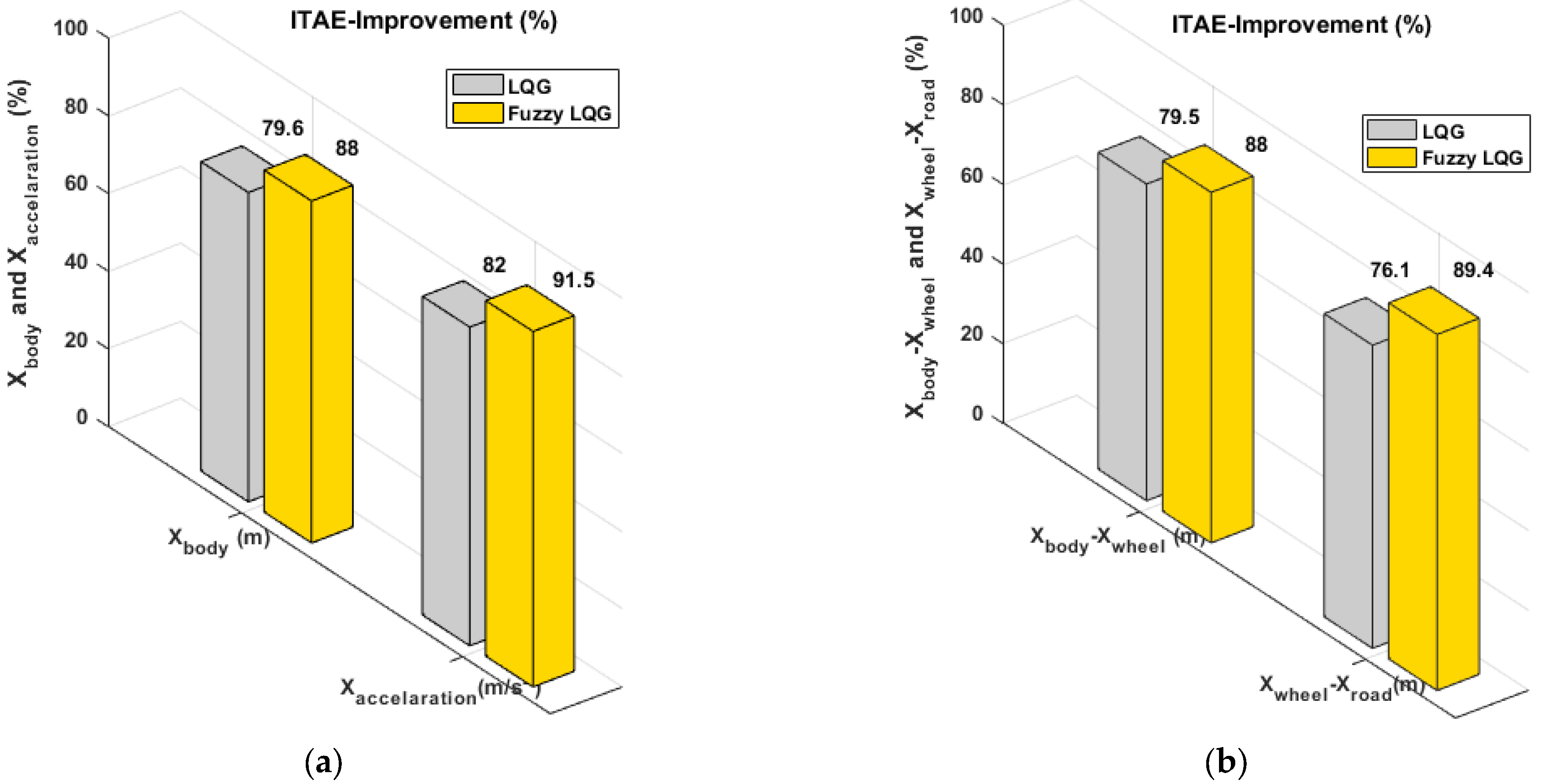
Table 3. The percentage improvement performance of the control methods based on the passive system was calculated using (35), and the results are shown in
Figure 11. The results are highlighted in blue and yellow for the fuzzy LQG and LQG methods, respectively.
As the car body motion’s lowest error results based on the RMSE performance criteria highlighted in bold in
Table 4, the lowest error was obtained using the fuzzy LQG method compared to the LQG control method. The error rate was about 0.0142 m for the fuzzy LQG method and 0.0094 m for the LQG method. When the acceleration error results were compared based on the used control methods, shown in
Table 4, the lowest value was recorded for the fuzzy LQG using the GWO control method compared to the LQG method. While the acceleration error was about 0.2746
for the fuzzy LQG using GWO, it was 0.0961
when using the LQG method.
According to the suspension clearance error results, the lowest error performance was obtained using the GWO-based fuzzy LQG method with 0.0185 m, and this value was 0.0237 m for the LQG method. In addition, the results based on the tire deviation error show that using the GWO-based fuzzy LQG method resulted in a lower error of about 0.0345 m. It is shown that the tire deviation error is about 0.00845 when the LQG method is used. When the force errors are compared using control methods, it is shown that the lowest force error result is obtained using the GWO-based fuzzy LQR control method, which is 121.74 N. However, this value is 293.83 N for the LQG method, as shown in
Table 4.
It is shown that the fuzzy LQG control method exhibits superior performance based on all parameters compared to the LQG method. The performance of all parameters is significantly increased compared to the passive system. When the fuzzy LQG control method is used, the of vehicle body movement performance increases by 79.6% while vehicle acceleration increases by 82%, and these improvements are 79.5% and 76.1% for the suspension deflection and tire deflection, respectively.
Table 5 compares the proposed fuzzy LQG method with other works.
As shown in
Table 5, the error values for vehicle body movement, vehicle acceleration, suspension deflection, and tire deflection are compared based on the PSO-based fuzzy LQR, harmonic, MPC, H-infinity control, and fuzzy LQG methods. Bold characters are used to highlight the lowest error performance values. It is seen that the results for the proposed fuzzy LQG control method are superior to all other existing methods.
In summary, the fuzzy LQG method (based on GWO) performs significantly better than the LQG method in reducing vibration amplitudes and acceleration fluctuations, making the vehicle more stable and responsive. Both methods outperform the passive suspension system, demonstrating that the active control strategies lead to better vehicle performance in terms of minimizing vibrations and improving ride comfort. Additionally, the results for suspension deflection and tire deflection further support the effectiveness of the applied control methods in enhancing overall vehicle dynamics.
The limitations of this study can be expressed as follows: In the model used in the study, variables such as environmental factors, road conditions, and driving style in real-world conditions are not included. Therefore, simulation results may not be equally effective in the real world. The performance of GWO may change, especially when the parameters are nonlinear or the system’s complexity increases. This study only presents valid results for the model given in the paper. The fuzzy LQG method used in the study is optimized under certain conditions. However, its ability to continuously adapt to changing conditions in the system (e.g., speed, load, road surface changes) may be limited. Applying the method in an experimental setting can overcome many of these limitations.


