
Modelling, Control Design and Inclusion of Articulated Robots in Cyber-Physical Factories †


Abstract
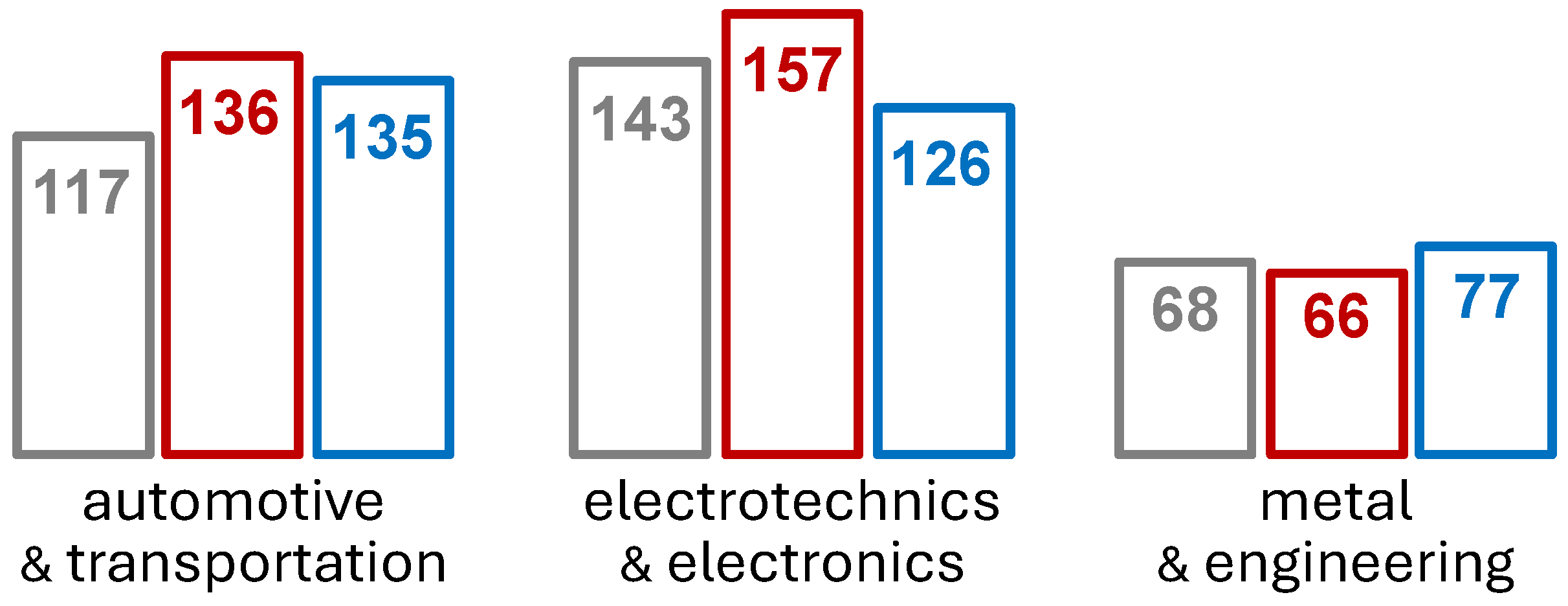
1. Introduction
2. Background of Analysis
3. Considering Robot Topology
4. Mathematical Model Synthesis
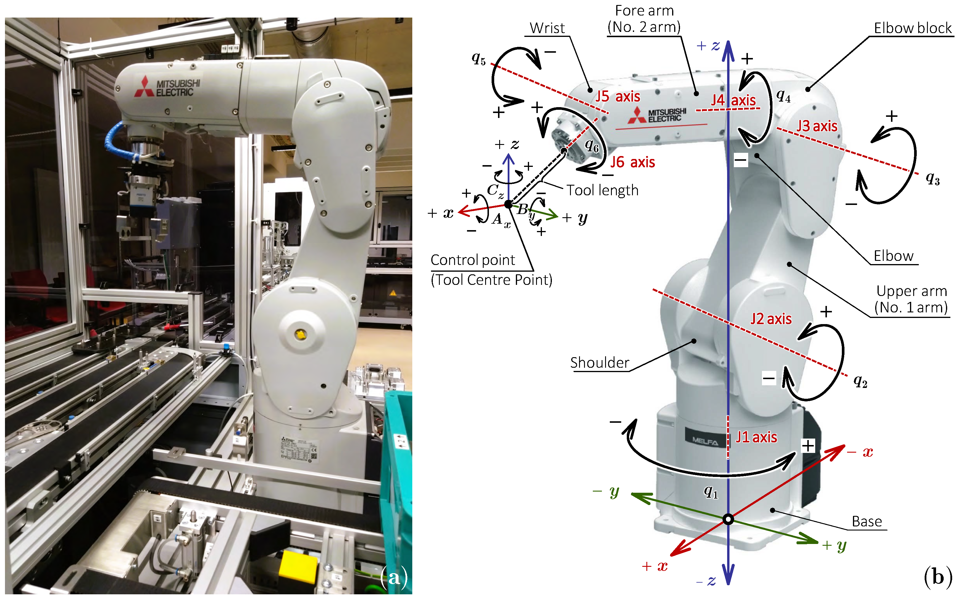
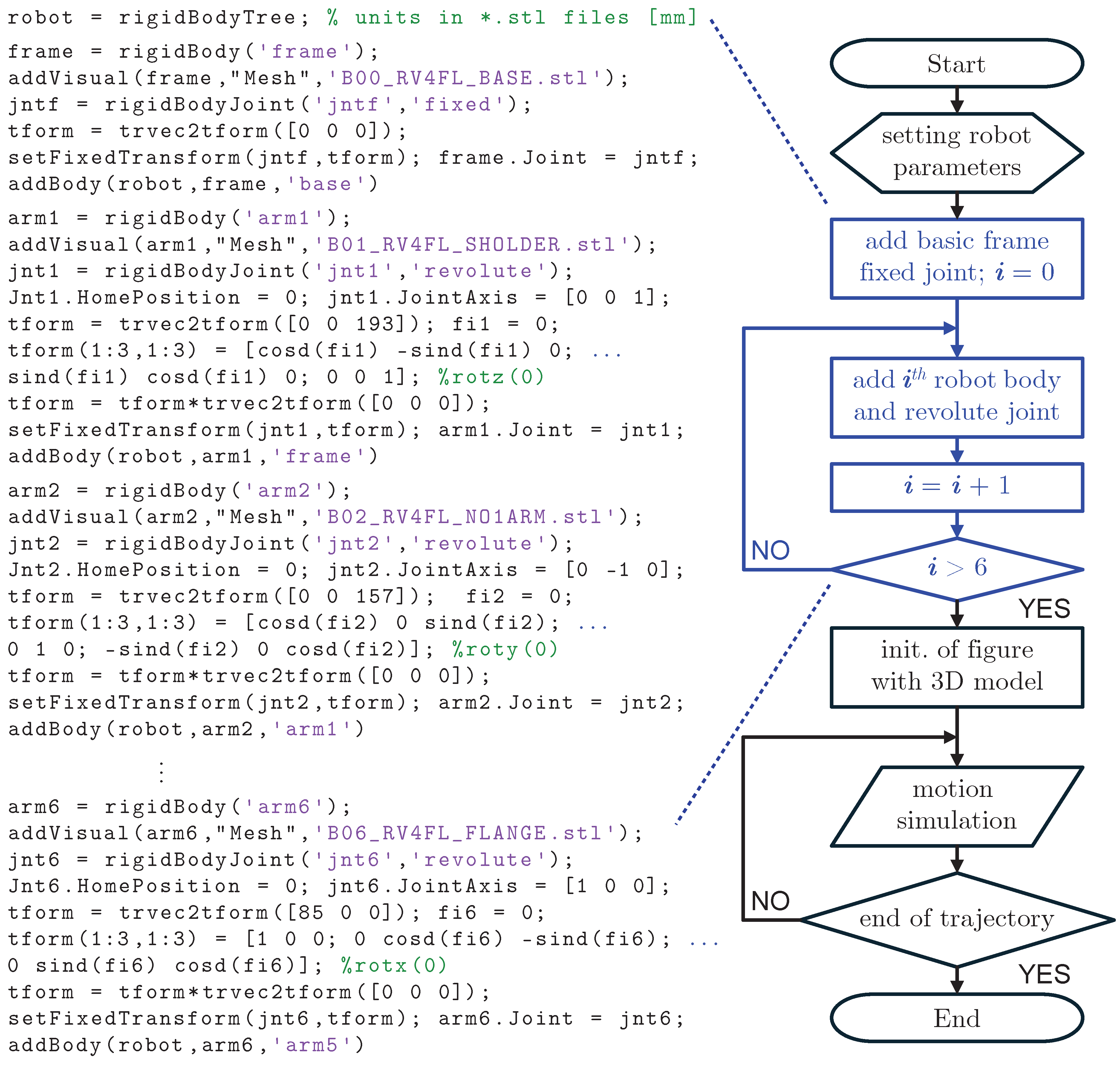
4.1. Model of Robot Kinematics
4.1.1. Forward Problem
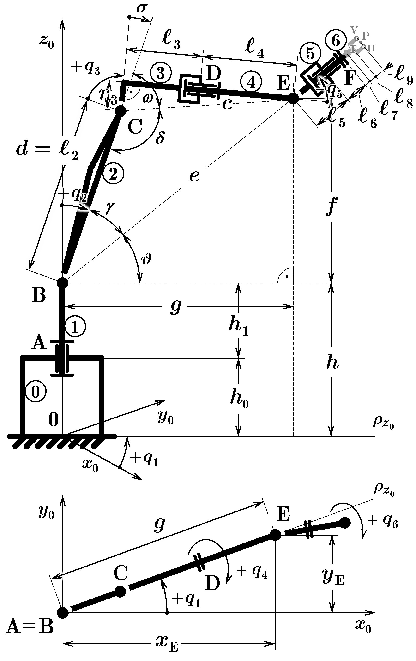
4.1.2. Inverse Problem
4.2. Model of Robot Dynamics
5. Control Concepts and Principles
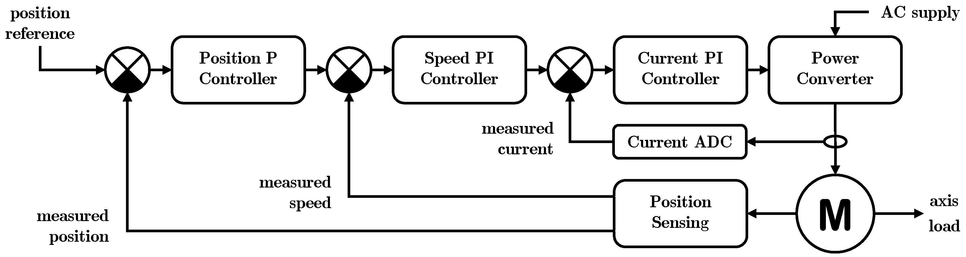
5.1. Conventional Cascade Control
- continuous form:
- discrete incremental form:
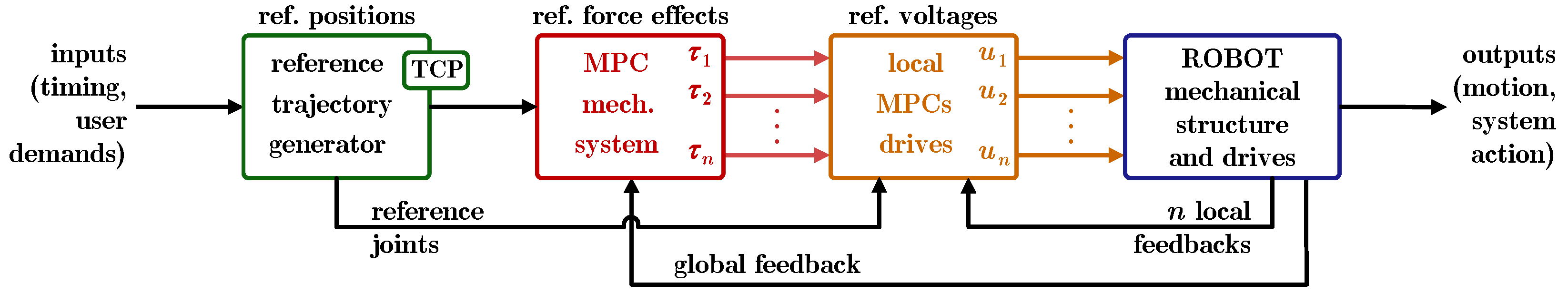
5.2. Advanced Model Predictive Control
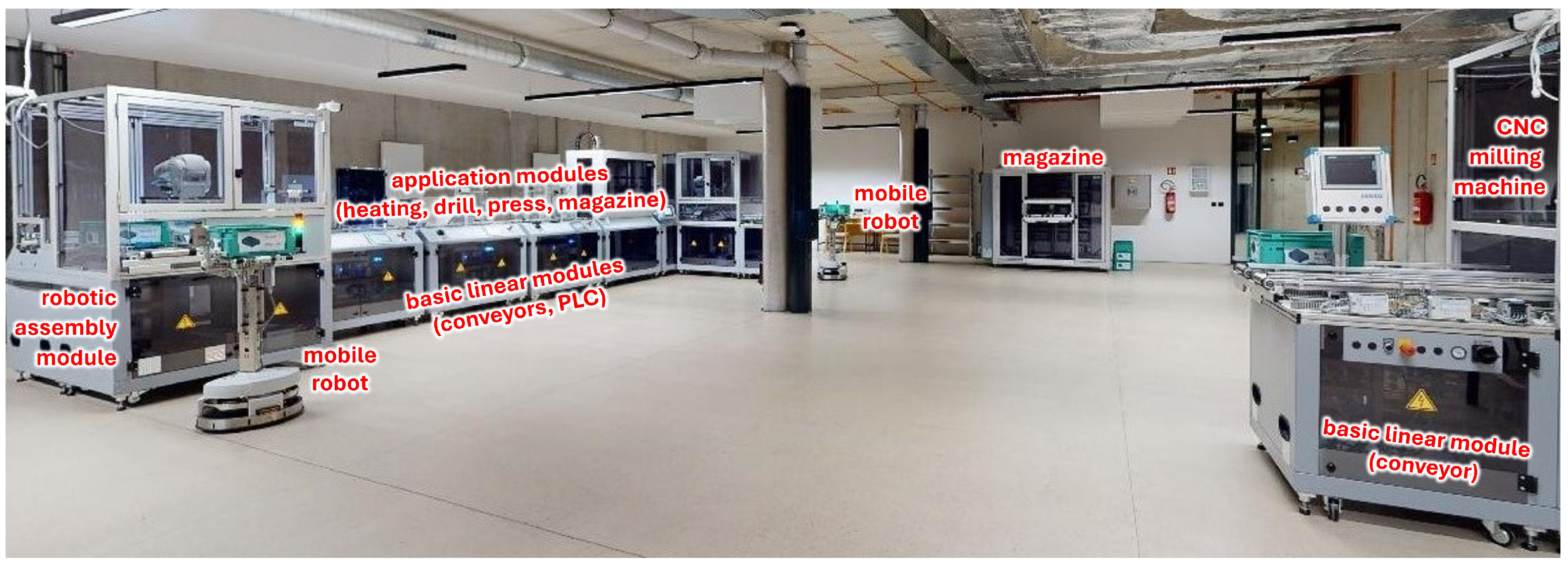
6. Software Tools
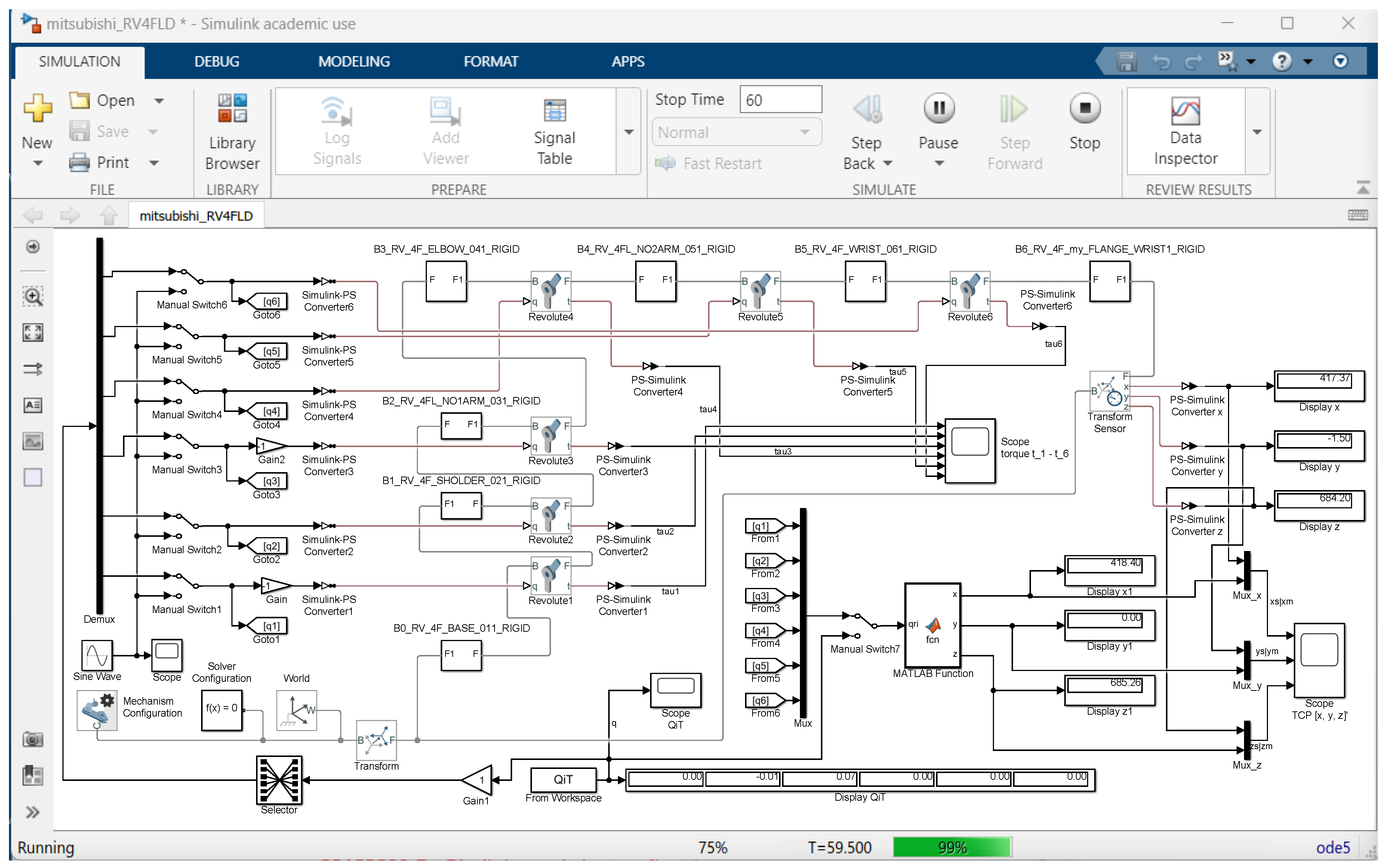
6.1. Simscape Multibody Lib—MathWorks
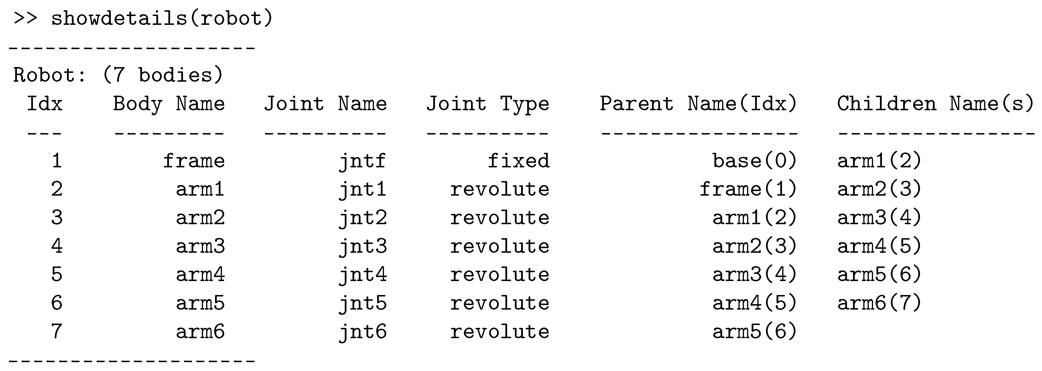
6.2. Robotics System Toolbox—MathWorks
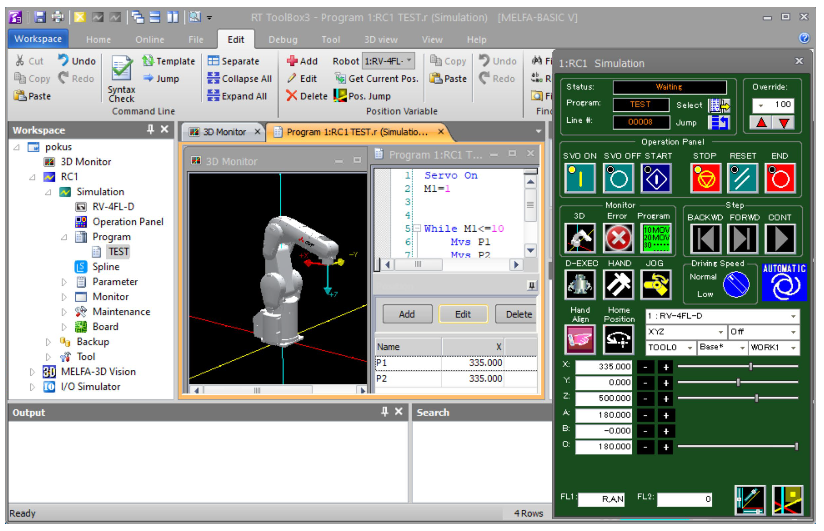
6.3. RT Toolbox—Mitsubishi Electric
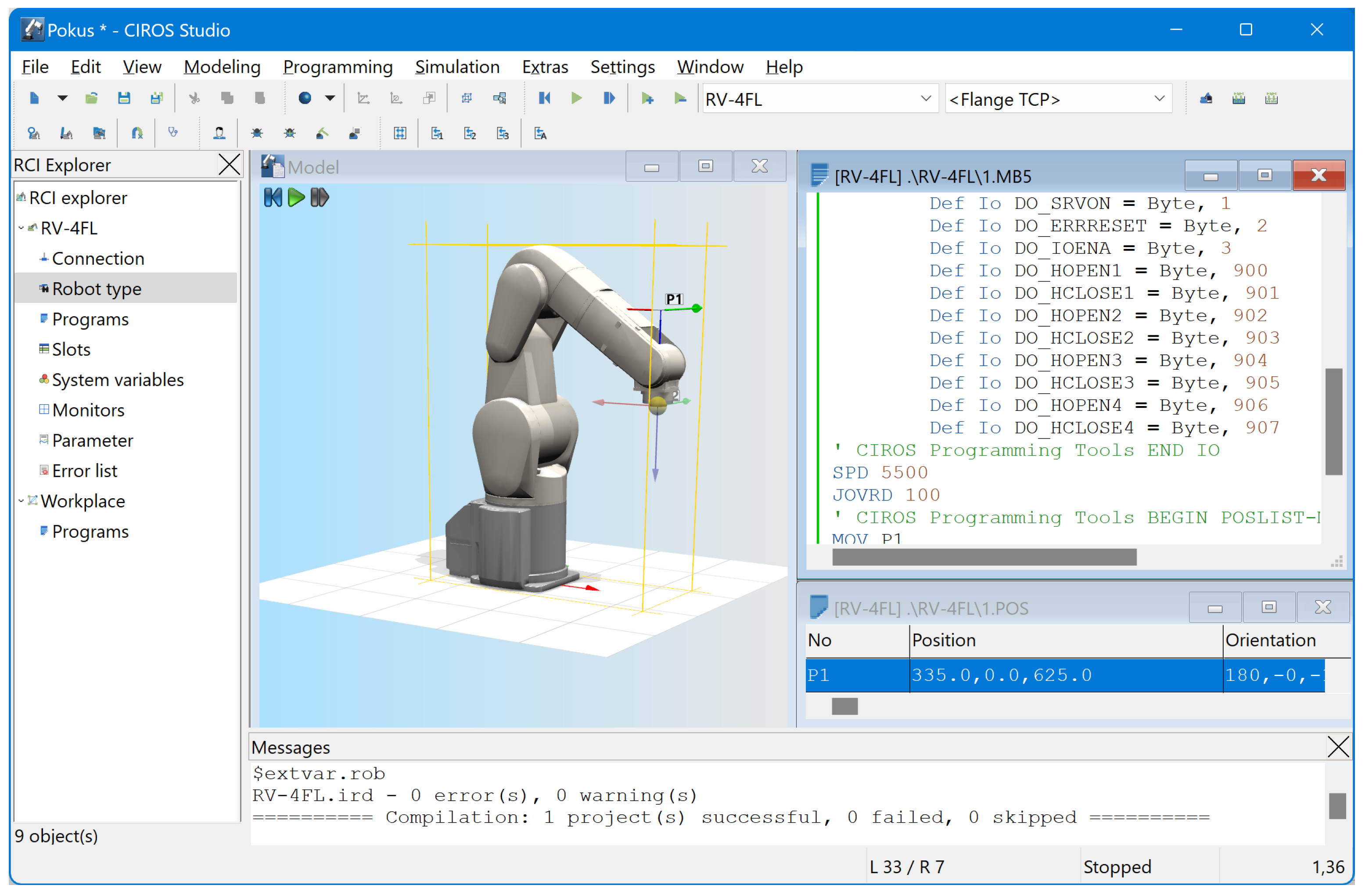
6.4. CIROS Studio—Festo
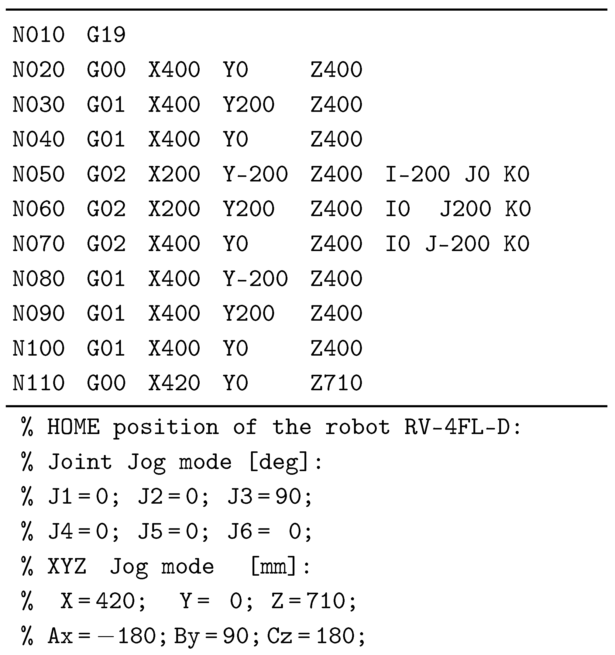
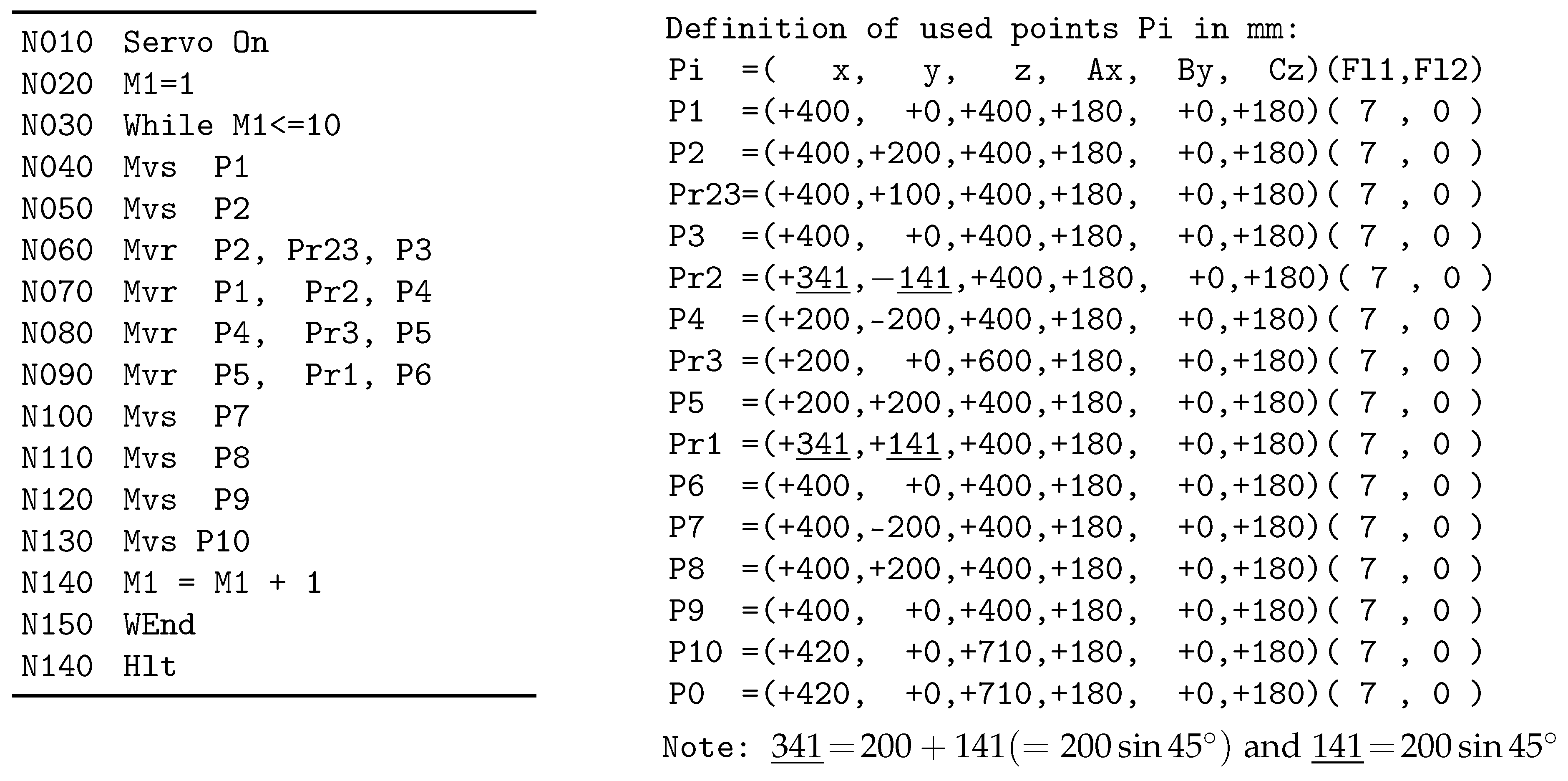
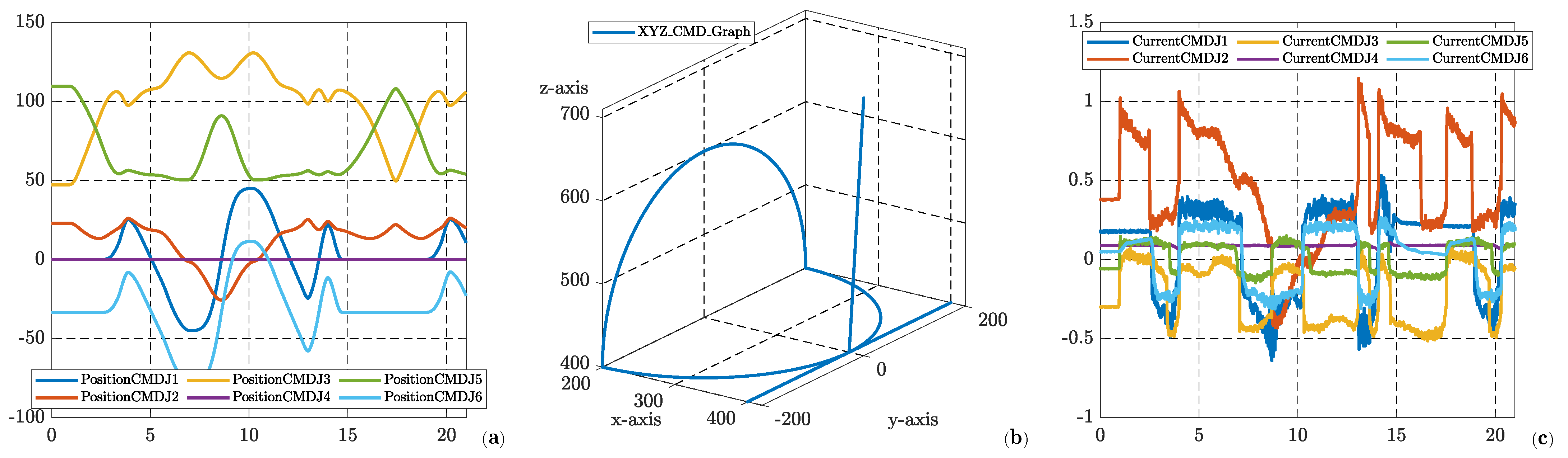
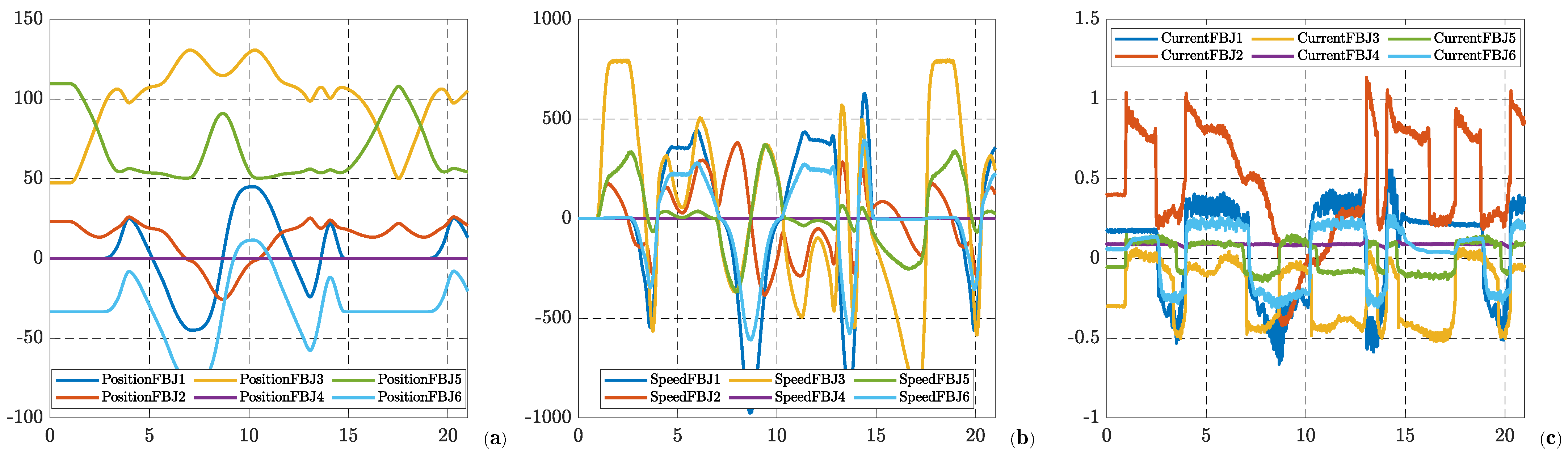
7. Simulation and Real Experiment
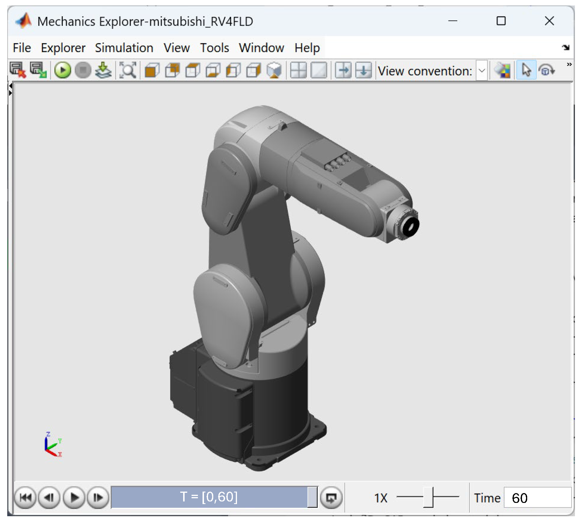
7.1. Simulation
7.2. Real Experimental Results
8. Robot Integration in Cyber-Physical Factories
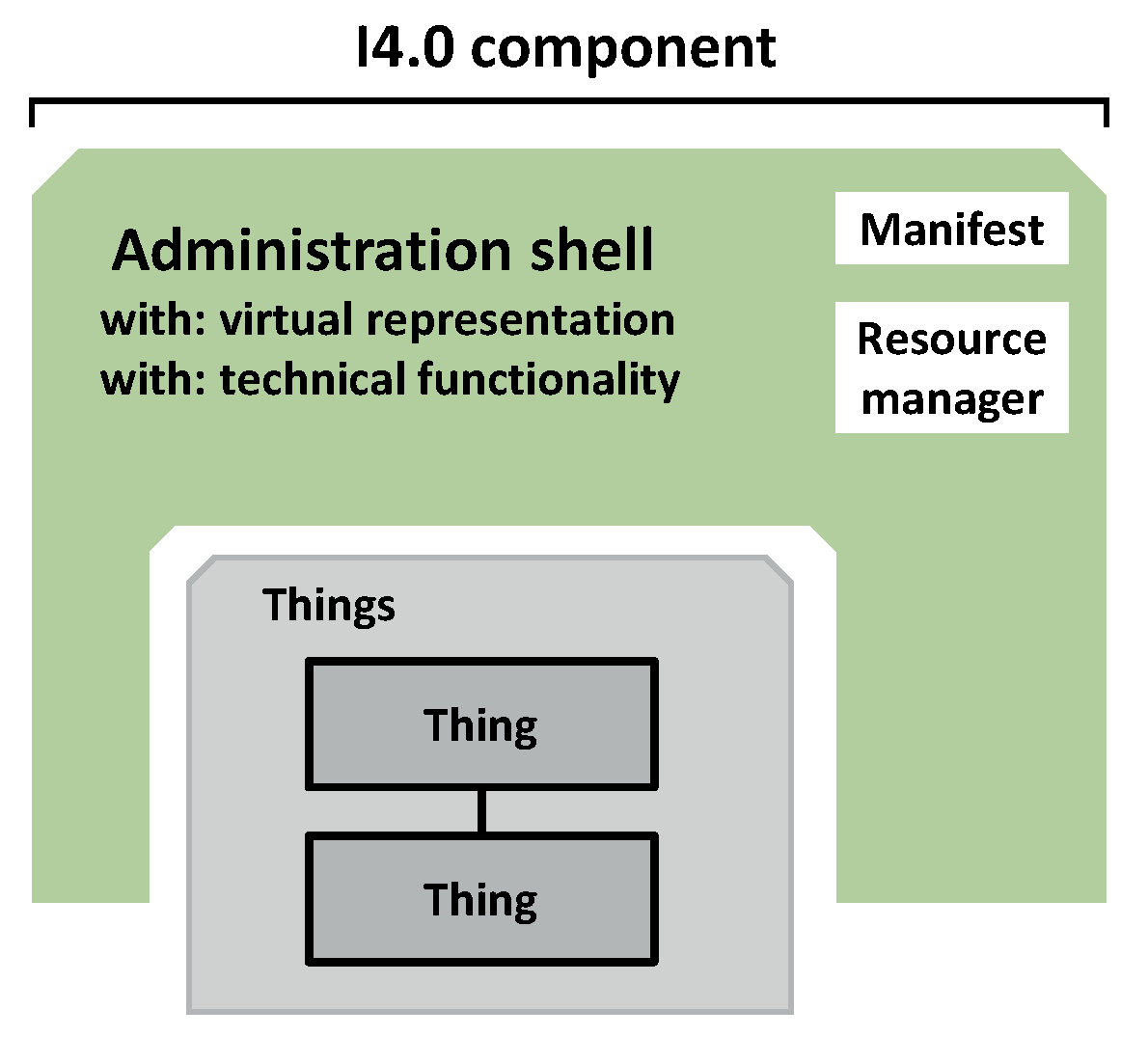
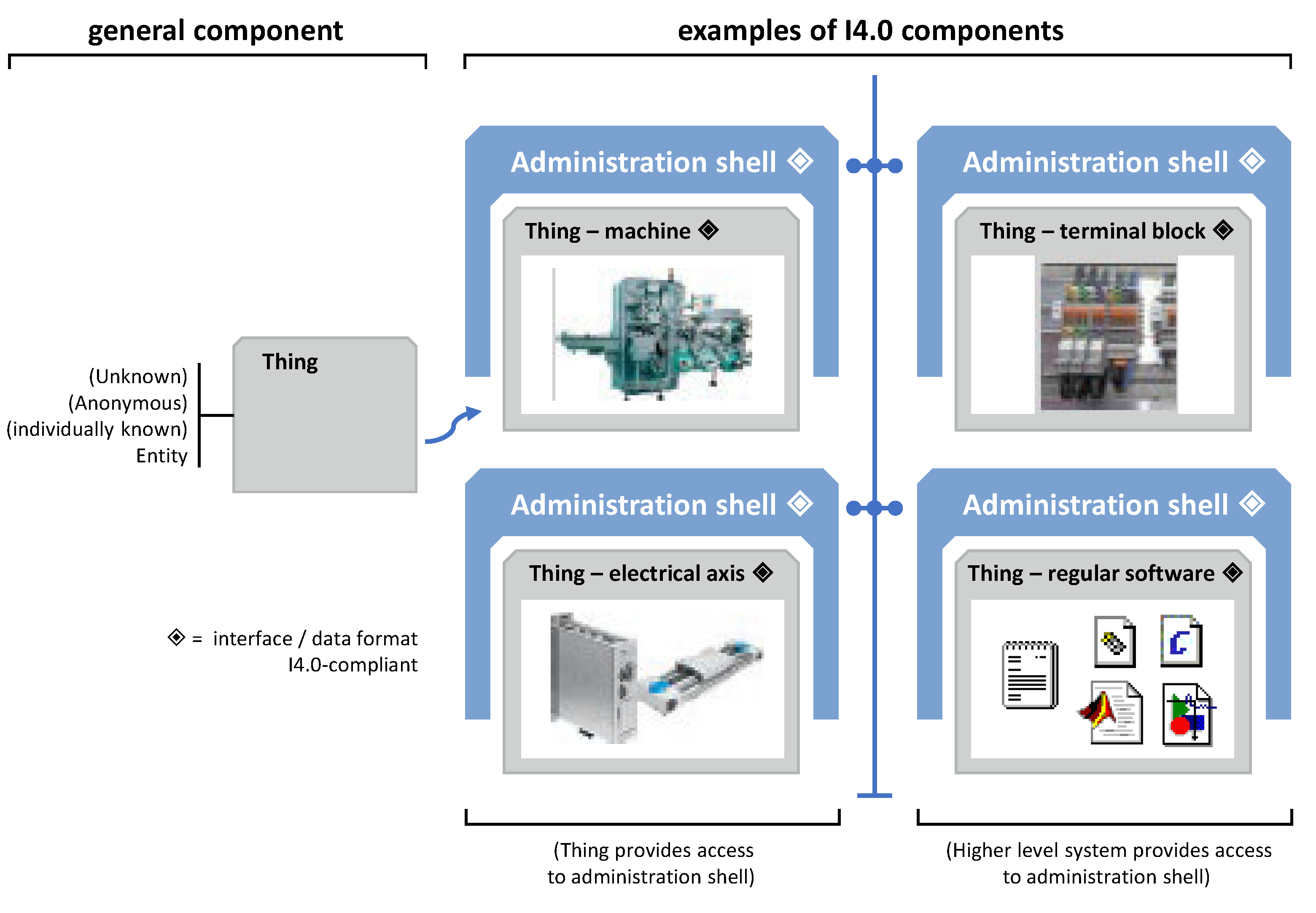
8.1. Asset Administration Shell
- passive part contains descriptions of parameters, properties and object abilities in prescribed format; this form means pieces of information and attributes that description has to contain of each parameter, but data format (XML, JSON),
- active part contains functions in any programming language used for communication for I4.0 components with their surroundings.
8.2. Application to Robots Mitsubishi—Full Digital Twin
9. Conclusions
Author Contributions
Funding
Data Availability Statement
Acknowledgments
Conflicts of Interest
Abbreviations
| ASS | Asset Administration Shell |
| CAD | Computer Aided Design |
| CPF | Cyber-Physical Factory |
| DH | Denavit–Hartenberg (concept/parameters) |
| DOF | Degree of Freedom |
| IFR | International Federation of Robotics |
| PID | Proportional–Integral–Derivative controller |
| PLC | Programmable Logic Controllers |
| TCP | Tool Centre Point |
| WR | World Robotics (statistical dept. of IFR |
| ZVEI | Association of the Electrical and Digital Industry |
References
- Jazar, R. Theory of Applied Robotics, 3rd ed.; Springer: Cham, Switzerland, 2010. [Google Scholar]
- Raza, M.; Kumar, P.M.; Hung, D.V.; Davis, W.; Nguyen, H.; Trestian, R. A Digital Twin Framework for I4.0 Enabling Next-Gen Manufacturing. In Proceedings of the 2020 9th International Conference on Industrial Technology and Management (ICITM). Oxford, UK, 11–13 February 2020; pp. 73–77. [Google Scholar] [CrossRef]
- Belda, K.; Jirsa, J. Control Principles of Autonomous Mobile Robots Used in Cyber-Physical Factories. In Proceedings of the 23rd International Conference on Process Control, Strbske Pleso, Slovakia, 1–4 June 2021; pp. 96–101. [Google Scholar]
- Hendzel, Z.; Trojnacki, M. Adaptive Fuzzy Control of a Four-Wheeled Mobile Robot Subject to Wheel Slip. Wseas Trans Syst. 2023, 22, 602–612. [Google Scholar] [CrossRef]
- Jiang, H.; Wang, Z.; Jin, Y.; Chen, X.; Li, P.; Gan, Y.; Lin, S.; Chen, X. Hierarchical control of soft manipulators towards unstructured interactions. Int. J. Robot. Resch. 2021, 40, 411–434. [Google Scholar] [CrossRef]
- Docimo, D. A Design Framework with Embedded Hierarchical Control Architecture Optimization. In Proceedings of the 2022 American Control Conference (ACC), Atlanta, GA, USA, 8–10 June 2022; pp. 3184–3191. [Google Scholar] [CrossRef]
- Saleem, O.; Abbas, F.; Iqbal, J. Complex Fractional-Order LQIR for Inverted-Pendulum-Type Robotic Mechanisms: Design and Experimental Validation. Mathematics 2023, 11, 913. [Google Scholar] [CrossRef]
- Afifa, R.; Ali, S.; Pervaiz, M.; Iqbal, J. Adaptive Backstepping Integral Sliding Mode Control of a MIMO Separately Excited DC Motor. Robotics 2023, 12, 105. [Google Scholar] [CrossRef]
- Awan, Z.S.; Ali, K.; Iqbal, J.; Mehmood, A. Adaptive backstepping based sensor and actuator fault tolerant control of a manipulator. J. Electr. Eng. Technol. 2019, 14, 2497–2504. [Google Scholar] [CrossRef]
- Vázquez-Hurtado, C.; Altamirano-Avila, E.; Roman-Flores, A.; Vargas-Martinez, A. Towards a Mixed Virtual Reality Environment Implementation to Enable Industrial Robot Programming Competencies within a Cyber-Physical Factory. In Proceedings of the 2023 IEEE Global Engineering Education Conference (EDUCON), Kuwait, Kuwait, 1–4 May 2023; pp. 1–8. [Google Scholar] [CrossRef]
- Gajdzik, B.; Wolniak, R. Influence of Industry 4.0 Projects on Business Operations: Literature and Empirical Pilot Studies Based on Case Studies in Poland. J. Open Innov. Technol. Mark. Complex. 2022, 8, 44. [Google Scholar] [CrossRef]
- Grabowska, S.; Saniuk, S.; Gajdzik, B. Industry 5.0: Improving humanization and sustainability of Industry 4.0. Scientometrics 2022, 127, 3117–3144. [Google Scholar] [CrossRef] [PubMed]
- Bilancia, P.; Schmidt, J.; Raffaeli, R.; Peruzzini, M.; Pellicciari, M. An Overview of Industrial Robots Control and Programming Approaches. Appl. Sci. 2023, 13, 2582. [Google Scholar] [CrossRef]
- Jwo, J.S.; Lee, C.H.; Lin, C.S. Data Twin-Driven Cyber-Physical Factory for Smart Manufacturing. Sensors 2022, 22, 2821. [Google Scholar] [CrossRef] [PubMed]
- Ryalat, M.; ElMoaqet, H.; AlFaouri, M. Design of a Smart Factory Based on Cyber-Physical Systems and Internet of Things Towards Industry 4.0. Appl. Sci. 2023, 13, 2156. [Google Scholar] [CrossRef]
- IFR. International Federation of Robotics, Global Statistics on Industrial Robots. 2025. Available online: https://ifr.org/wr-industrial-robots/ (accessed on 1 January 2025).
- Belda, K.; Venkrbec, L. Control Principles of Stationary Articulated Robots Used in Cyber-Physical Factories. In Proceedings of the 27th International Conference on Circuits, Systems, Communications and Computers (CSCC), Rhodes, Greece, 19–22 July 2023. [Google Scholar]
- Belda, K.; Píša, P. Explicit Model Predictive Control of PMSM Drives. In Proceedings of the 2021 IEEE 30th International Symposium on Industrial Electronics, Kyoto, Japan, 20–23 June 2021; pp. 1–6. [Google Scholar]
- Mitsubishi Electric. RV-FR Series, Instruction Manual, Robot Arm Setup & Maitenance, BFP-A3474-N. 2022. Available online: https://dl.mitsubishielectric.com/dl/fa/document/manual/robot/bfp-a3474/bfp-a3474r.pdf (accessed on 15 May 2024).
- Belda, K.; Rovný, O. Predictive Control of 5 DOF Robot Arm of Autonomous Mobile Robotic System Motion Control Employing Mathematical Model of the Robot Arm Dynamics. In Proceedings of the 21st International Conference on Process Control, Strbske Pleso, Slovakia, 6–9 June 2017; pp. 339–344. [Google Scholar]
- Belda, K. Mathematical modelling and predictive control of permanent magnet synchronous motor drives. Trans. Electr. Eng. 2013, 2, 114–120. [Google Scholar]
- Prokop, L.; Grasblum, P. 3-Phase PM Synchronous Motor Vector Control Using a 56F80x, 56F8100, or 56F8300 Device. Freescale Semi—Conductor Application Note. 2005. Available online: https://www.nxp.jp/docs/en/application-note/AN1931.pdf (accessed on 20 January 2022).
- Belda, K. Nonlinear Model Predictive Control Algorithms for Industrial Articulated Robots. In Informatics in Control, Automation and Robotics: ICINCO, Revised Selected Papers; Springer: Berlin/Heidelberg, Germany, 2019; pp. 230–251. [Google Scholar]
- MathWorks. Simscape TM MultibodyTM, User’s Guide; MathWorks: Natick, MA, USA, 2024. [Google Scholar]
- MathWorks. Robotics System ToolboxTM, User’s Guide; MathWorks: Natick, MA, USA, 2024. [Google Scholar]
- Belda, K.; Dvořák, K. Path Modeling and 3D Robot Visualization for Model-Based Control of Articulated Robots. In Proceedings of the Preprints 15th European Workshop on Advanced Control and Diagnosis, Bologna, Italy, 21–22 November 2019; pp. 1–16. [Google Scholar]
- Mitsubishi Electric. RT ToolBox3/RT ToolBox3 mini, User’s Manual, BFP-A3495-L. 2020. Available online: https://dl.mitsubishielectric.com/dl/fa/document/manual/robot/bfp-a3495/bfp-a3495u.pdf (accessed on 15 May 2023).
- ZVEI. Reference Architecture Model Industrie 4.0 (RAMI4.0). 2015. Available online: https://www.zvei.org/fileadmin/user_upload/Presse_und_Medien/Publikationen/2016/januar/GMA_Status_Report__Reference_Archtitecture_Model_Industrie_4.0__RAMI_4.0_/GMA-Status-Report-RAMI-40-July-2015.pdf (accessed on 10 March 2023).
- IDTA; ZVEI. Details of the Asset Administration Shell, Part 1—The Exchange of Information Between Partners in the Value Chain of Industrie 4.0 (Version 3.0RC02). 2022. Available online: https://digitalcollection.zhaw.ch/server/api/core/bitstreams/58284191-48b7-4870-8296-6ef1f3f307ad/content (accessed on 20 November 2024).
- IDTA; ZVEI. Details of the Asset Administration Shell, Part 2—Interoperability at Runtime—Exchanging Information via Application Programming Interfaces (Version 1.0RC02). 2022. Available online: https://digitalcollection.zhaw.ch/server/api/core/bitstreams/35301a19-fade-444f-bb40-8975bad47f48/content (accessed on 10 December 2023).
- ZVEI. Association of the Electrical and Digital Industry. 2023. Available online: https://www.zvei.org/en/ (accessed on 10 June 2024).


| Robot | D-H Parameters | |||
|---|---|---|---|---|
| Body Names | ||||
| Base (0–1) | 0 | |||
| Shoulder (1–2) | 0 | |||
| Upper arm (2–3) | 0 | |||
| Elbow ver. (3–) | 0 | |||
| Elbow hor. (–4) | 0 | |||
| Fore arm (4–5) | 0 | |||
| Wrist (5–6) | 0 | |||
| Flange (6–T) | 0 | |||
Disclaimer/Publisher’s Note: The statements, opinions and data contained in all publications are solely those of the individual author(s) and contributor(s) and not of MDPI and/or the editor(s). MDPI and/or the editor(s) disclaim responsibility for any injury to people or property resulting from any ideas, methods, instructions or products referred to in the content. |
© 2025 by the authors. Licensee MDPI, Basel, Switzerland. This article is an open access article distributed under the terms and conditions of the Creative Commons Attribution (CC BY) license (https://creativecommons.org/licenses/by/4.0/).
Share and Cite
Belda, K.; Venkrbec, L.; Jirsa, J. Modelling, Control Design and Inclusion of Articulated Robots in Cyber-Physical Factories. Actuators 2025, 14, 129. https://doi.org/10.3390/act14030129
Belda K, Venkrbec L, Jirsa J. Modelling, Control Design and Inclusion of Articulated Robots in Cyber-Physical Factories. Actuators. 2025; 14(3):129. https://doi.org/10.3390/act14030129
Chicago/Turabian StyleBelda, Květoslav, Lukáš Venkrbec, and Jan Jirsa. 2025. "Modelling, Control Design and Inclusion of Articulated Robots in Cyber-Physical Factories" Actuators 14, no. 3: 129. https://doi.org/10.3390/act14030129
APA StyleBelda, K., Venkrbec, L., & Jirsa, J. (2025). Modelling, Control Design and Inclusion of Articulated Robots in Cyber-Physical Factories. Actuators, 14(3), 129. https://doi.org/10.3390/act14030129