Article

Fuzzy Course Tracking Control of Unmanned Surface Vehicle with Actuator Input Quantization and Event-Triggered Mechanism

by
Qifu Wang
,
Chenchen Jiang
,
Jun Ning
*,
Liying Hao
and
Yong Yin
College of Navigation, Dalian Maritime University, Dalian 116026, China
*
Author to whom correspondence should be addressed.
Actuators 2025, 14(3), 130; https://doi.org/10.3390/act14030130
Submission received: 14 January 2025 / Revised: 20 February 2025 / Accepted: 4 March 2025 / Published: 7 March 2025
(This article belongs to the Special Issue Control System of Autonomous Surface Vehicle)

Abstract

:
This paper discusses the course tracking control of unmanned surface vehicles with actuator input quantization and an event-triggered mechanism. The system control laws are designed based on the backstepping method, combining dynamic surface control technology to mitigate the computational complexity expansion of virtual control laws. A fuzzy logic system can be used to approximate the uncertainties in the control system. The control system’s control inputs are quantized by using uniform quantizers. Then, the event-triggered adaptive fuzzy quantization control method is introduced, which can reduce the frequency of control actions and effectively reduce the communication burden. The stability of the control system is rigorously proven using Lyapunov stability theory, ensuring that all signals in the closed-loop system remain bounded. Finally, simulation tests are used to show the algorithm’s efficiency and usefulness.

1. Introduction

In recent years, course tracking control of Unmanned Surface Vehicles (USVs) has always been an important area of research and exploration for scholars. Due to the influence of factors such as velocity, loading status, and external disturbances like wind, waves, and currents [1,2], it is not easy for the course controller to achieve the desired effect.
USV course control has always been an important research direction in the field of ship control. Recently, researchers have applied many advanced control techniques to course tracking control [3,4,5], sliding mode control [6,7,8], robust control [9,10], adaptive control [11,12,13], fuzzy control [14,15,16,17], and neural network control [18,19], etc. In [20], a robust ship heading controller design method combining the backstepping technique and adaptive control theory is proposed to solve the ship heading adaptive tracking problem and effectively eliminate the influence of interference. Ref. [21] proposes a heading control strategy that combines neural network and PID control methods, aiming to generate the optimal control strategy in real-time and realize efficient and accurate heading control in a complex and changing operating environment. In [22], a new heading control law is suggested for USVs that are exposed to external disturbances. A disturbance observer is designed to compensate for the external disturbance to further improve the robustness of the heading control strategy. However, the above literature primarily focuses on developing better control schemes to improve the precision and consistency of USV course tracking. Unlike conventional surface vessels, which may rely on more stable communication infrastructures, USVs’ communication systems depend entirely on wireless channels. These channels are prone to issues such as input quantization and limited communication bandwidth, posing additional challenges for control design.
In ship navigation, information is exchanged between components through communication channels [23,24]. Control system signals are usually quantized and encoded before transmission. Additionally, since navigation communication channels typically have very limited bandwidth, quantization methods can help reduce both the actuator’s operating frequency and the communication rate while maintaining compliance with the specified bandwidth constraints [24,25,26]. Ref. [27] studies the quantized feedback stability of nonlinear systems with external disturbances by introducing a dynamic quantizer with quantization parameters. Different quantization schemes for input and output are considered, and sufficient conditions for closed-loop stability are derived using the update protocol and Lyapunov method. In [28], control and quantisation inputs are linkted to mitigate discontinuities in the virtual control law introduced by state quantisation, and a new adaptive neural network control algorithm is proposed to manage unbounded quantisation errors. In [29], signal quantization addresses the problem of limited communication channel capacity in network-based USV heading tracking control under wave interference. In [30], the quantizers quantize the corresponding virtual augmentation vectors to obtain an estimate of the controller output. However, current research primarily treats quantized variables as disturbances to unquantized variables, and the disturbance boundary produced by the quantizer is then examined to assess the impact of quantization on system performance.
Input quantization corresponds to the operational principles of controllers in navigation applications, but it does not fundamentally resolve the issue of energy consumption. Therefore, there has been a lot of interest in using event-triggered control techniques [31,32,33,34,35]. In [36], the sliding mode control method is combined with event-triggered mechanisms to design a quantization feedback control system. Ref. [37] focuses on employing an event-triggered technique to regulate the adaptive fuzzy output feedback path tracking for autonomous surface vessels. The event-triggered controller samples the vessel’s motion state, position, and heading only when triggering conditions are met. In [38], the event-triggered mechanism allows the controller to sample the guidance heading angle only when specific triggering conditions are met, thereby reducing the update frequency. In order to provide safe navigation in confined waters during mode switching, the event-triggered method helps maintain limitations on position and heading errors in both path-following and collision avoidance modes. However, the aforementioned studies primarily focus on using event-triggered techniques to save communication resources. Consequently, it is critical to research control systems that consider the servo system characteristics and employ event-triggered mechanisms and input quantization.
Based on these results, this paper comprehensively considers the characteristics of the rudder servo system and focuses on input quantization for USV course tracking control. To eliminate the requirement that the process control subsystem’s quantization parameters be known in advance, this paper proposes a linear analytical model to describe the input quantization process. Additionally, the uncertainty of the internal model is approximated using a fuzzy logic system. An event-triggered adaptive fuzzy quantization control mechanism is proposed, which significantly reduces the communication load and improves the efficiency of communication resource utilization. Lyapunov stability theory is used to rigorously verify the stability of the suggested control framework. Lastly, the simulation results prove that the proposed algorithm is useful and effective. The main contributions of this paper, in comparison to previous research, are summarized as follows:
(1)
In comparison with the existing ship course tracking control methods [39,40,41], the course tracking control of USVs with actuator input quantization and an event-triggered mechanism is considered for the first time, which also solves the computational inflation problem with dynamic surface control.
(2)
In comparison with the existing controller design [42,43,44], the input quantization process is described by a linear model; in addition, this paper fully considers the characteristics of the steering servo system, making it more practically significant.

2. Problem Formulation

The mathematical model of USV heading control can be expressed via the following [45]:
φ · · + K T α φ · + β φ · 3 = K T δ ,
where φ denotes the ship’s heading angle; φ ˙ is the ship’s yawing rate; δ is the ship’s rudder angle; K T is the control system’s gain where K and T are indices related to the ship’s maneuverability; and α and β are parameters that exhibit nonlinearity.
When considering the characteristics of the rudder servo system, the dynamic characteristics of the rudder can be described using the following [46]:
δ · = 1 T E δ + K E T E δ E ,
where δ E indicates the commanded rudder angle from the actuator, δ signifies the actual rudder angle, K E represents the actuator’s control gain, and T E is the actuator’s time constant.
In this paper, the quantization of the actuator is discussed, and the uniform quantizer is denoted as
Q u = o · round u o ,
where the quantified level is represented by o. The control signal u changes to Q ( u ) after going through the quantizer.
This paper’s objective is to create an ideal reference trajectory φ d R , where φ d is continuously differentiable, and its derivative is φ d · . This paper’s control purpose is to address the USV heading tracking issue under the assumption of a given ideal heading, that is,
lim t φ φ d m ,
where φ is the real USV course and m is a tiny normal constant.

3. Controller Design

This section includes controller design and analysis. Furthermore, it introduces a fuzzy logic system for the USV course control system in order to handle the uncertainties in the system model.
Let x 1 = φ , x 2 = φ · , x 3 = δ , and the system control input u = δ E , which is the commanded rudder angle.
According to (1),
x · 1 = x 2 , x · 2 = f 1 ( x 2 , t ) + a 1 x 3 + Δ 1 , x · 3 = f 2 ( x 3 , t ) + a 2 Q ( u ) + Δ 2 .
where f 1 ( x 2 , t ) = m 2 x 2 + m 3 x 2 3 , m 2 = K T α , m 3 = 1 T E , f 2 ( x 3 , t ) = m 3 x 3 , a 1 = K T , a 2 = K E T E , and Δ 1 and Δ 2 are unknown disturbances in the system model.
Assumption 1.
The ideal angle x 1 d is bounded and its first- and second-order derivatives exist and satisfy x 1 d 2 + x 1 d · 2 + x 1 d · · 2 ξ for positive values of ξ. The physical parameters of the system are unknown—specifically, a 1 and a 2 —but their bounds are known. That is, there exist known positive numbers a i m and a i M , i = 1, 2, such that a i m a i a i M . The function f 1 x 2 , t , f 2 x 3 , t is unknown in its closed form.
Letting Q u = q 1 t u + q 2 t , we have
q 1 ( t ) = Q ( u ( t ) ) u ( t ) | u ( t ) | b , 1 | u ( t ) | < b , q 2 ( t ) = 0 | u ( t ) | b , Q ( u ( t ) ) u ( t ) | u ( t ) | < b ,
where q 1 t is unknown. Given that the sign remains constant during quantization, q 1 t is always greater than 0. When | u t | < b , Q u t is bounded, which implies that q 2 t is also bounded. We can take | q 2 t | q ¯ 2 , and so the system controller is designed as follows:
Step one: Define the first error
S 1 = x 1 x 1 d .
The derivative of Equation (7) is as follows:
S 1 · = x 2 x 1 d · .
The virtual control is set as follows:
x 2 ¯ = c 1 S 1 + x 1 d · .
The system inputs x 2 into a first-order low-pass filter with a time constant of τ 2 and obtains a new state variable x 2 d .
τ 2 x 2 d · + x 2 d = x 2 ¯ , x 2 d 0 = x 2 ¯ 0 .
Step two: Define the second error
S 2 = x 2 x 2 d .
The following is the derivative of Equation (11):
S 2 · = a 1 [ x 3 + 1 a 1 f 1 x 2 , t + 1 a 1 ( Δ 1 t x 2 d · ) ] .
According to the universal approximation theorem [47], a fuzzy logic system with a sufficient number of rules can approximate any continuous function on a compact domain to arbitrary accuracy. Specifically, for any given tiny constant ϵ N , there exists an optimal fuzzy logic system W T h ( X ) such that the approximation error satisfies
Δ ( X ) = W T h ( X ) + ϵ ,
where the fuzzy system’s ideal weight is represented by W , its fuzzy basis vector is represented by h ( X ) , its approximation error is represented by ϵ , and | ϵ | ϵ N . This property is particularly useful in control systems when dealing with unknown nonlinear functions, such as 1 a 1 f 1 ( x 2 , t ) in this context. By employing the fuzzy logic system, we can effectively approximate the unknown dynamics.
Let Δ ^ ( X ) be the estimate of Δ ( X ) . It follows that
Δ ^ ( X ) = W ^ T h ( X ) ,
where W ^ is the estimate of W , and
W = arg min W Ω sup X R Δ ^ X | W Δ X ,
therefore,
1 a 1 f 1 x 2 , t = W 1 T h 1 x 2 + ϵ 1 , | ϵ 1 | ϵ M ; W 1 W M .
Define
W 1 T φ 1 = W 1 T h 1 x 2 + 1 a 1 ( ρ 1 2 S 2 2 ϵ x 2 d · + c 2 S 2 ) ,
where c 2 is a positive number, ϵ is an arbitrarily small positive number, ρ is a positive number, and ρ 1 2 S 2 / 2 ϵ is a nonlinear damping term used to overcome Δ 1 t .
Set the virtual control rate as
x 3 ¯ = W 1 T ^ φ 1 ,
where W 1 ^ is an estimate of W 1 .
The design adaptive rate is as follows:
W 1 ^ · = Γ 1 φ 1 S 2 Γ 1 η 1 W 1 ^ ,
where Γ 1 is a positive definite symmetric matrix and η 1 is a positive real number.
The system inputs x 3 into a first-order low-pass filter with a time constant of τ 3 and obtains a new state variable x 3 d .
τ 3 x 3 d · + x 3 d = x 3 ¯ , x 3 d 0 = x 3 ¯ 0 .
Step three: Define the third error
S 3 = x 3 x 3 d .
The derivative of Equation (19) is as follows:
S 3 · = a 2 [ Q u + 1 a 2 f 2 x 3 , t + 1 a 2 ( Δ 2 t x 3 d · ) ] ,
where
1 a 2 f 2 x 3 , t = W 2 T h 2 x 3 + ϵ 2 , | ϵ 2 |   ϵ M ; W 2 W M .
Define
W 2 T φ 2 = W 2 T h 2 x 3 + 1 a 2 ( ρ 2 2 S 3 2 ϵ x 3 d · + c 3 S 3 ) .
where c 3 is a positive number, ρ 2 2 S 3 / 2 ϵ is a nonlinear damping term used to overcome Δ 2 t .
The design adaptive rate is as follows:
W 2 ^ · = Γ 2 φ 2 S 3 Γ 2 η 2 W 2 ^ ,
where Γ 2 is a positive definite symmetric matrix and η 2 is a positive real number.
Since q 1 t varies with time and is unknown, adaptive estimation is employed. To avoid singularity issues that occur when the estimate is zero, the lower bound of q 1 t is used for estimation. A time-varying gain is defined as μ = 1 q 1 t min , where q 1 t min represents the lower bound of q 1 t .
The adaptive law and event-triggered adaptive fuzzy quantization control law are designed as
u = m ¯ tanh ( S 3 m ¯ ω ) S 3 μ ^ 2 u ¯ 2 | S 3 μ ^ u ¯ | + v ,
W ^ · = S 3 u ¯ σ μ ^ ,
where v and σ are positive constants. Based on the quantification of the actuator and considering the need to reduce the communication load of the input signal [48,49], the design of an event-triggered control method is as follows: u = τ t k , for all t t k , t k + 1 ,
t k + 1 = inf { t R , | e τ t |   m } , t 1 = 0 .
where m is a time constant that satisfies 0 < m < m ¯ , and e u t represents the tracking error given by e u t = τ t u t . According to [50], there exists a continuous time-varying coefficient λ t , which satisfies λ t k = 0 , λ t k + 1 = ± 1 , and | λ t | 1 , leading to the following: τ t = u t + m λ t . From this, it follows that
u t = τ t λ t m .
Equation (27) is analyzed as follows:
(1)
When λ t = 0 , | e u t | = | τ t u t | = 0 , which implies that t = t k and τ = u t k ;
(2)
When | λ t | < 1 , | e u t | = | τ t u t | < m , which implies that t t k , t k + 1 ;
(3)
When | λ t | = 1 , | e u t | = m , meaning that the current moment is t = t k + 1 , and u = τ t k + 1 .
The same logic applies to the analysis for t t k + 1 , t k + 2 . Thus, at any given moment, the relationship τ t = u t + m λ t , where λ t satisfies the aforementioned conditions.

4. Stability Analysis

The stability analysis of the suggested controllers is presented in this section.
Define the filtering error as
y i = x i d x i ¯ , i = 2 , 3 .
x i d · = y i τ i .
Define the weight estimation error as
W ˜ i = W ^ i W i , i = 2 , 3 .
Derivation of each error yields
S 1 · = S 2 + y 2 + x 2 ¯ x 1 d · = S 2 + y 2 c 1 S 1 ,
and
S 2 · = a 1 [ S 3 + y 3 + x 3 ¯ + W T h 1 x 2 + ϵ 1 + 1 a 1 ( Δ 1 x 2 d · ) ] = a 1 [ S 3 + y 3 W 1 ^ T φ 1 + W 1 T φ 1 + ϵ 1 + 1 a 1 ( Δ 1 ρ 1 2 S 2 / 2 ϵ c 2 S 2 ) ] = a 1 ( S 3 + y 3 W 1 ˜ T φ 1 + ϵ 1 ) + ( Δ 1 ρ 1 2 S 2 2 ϵ c 2 S 2 ) ,
and
S 3 · = a 2 [ q 1 u + q 2 + W 2 T h 2 x 3 + ϵ 2 + 1 a 2 ( Δ 2 x 3 d · ) ] = a 2 [ q 1 u + q 2 + W 2 T φ 2 + ϵ 2 + 1 a 2 ( Δ 2 ρ 2 2 S 3 / 2 ϵ c 3 S 3 ) ] = a 2 ( q 1 u W 2 ˜ T φ 2 + ϵ 2 + W 2 ^ T φ 2 ) + ( Δ 2 ρ 2 2 S 3 / 2 ϵ c 3 S 3 + q 2 ) .
Deriving the error for each virtual control term yields
y 2 · = x 2 d · x 2 ¯ · = y 2 / τ 2 + c 1 S 1 · x 1 d · · ,
and
y 3 · = x 3 d · x 3 ¯ · = y 3 / τ 3 + W 1 ^ · T φ 1 + W 1 ^ T φ 1 · .
There exist upper bound functions B i , i = 2, 3, such that
y 2 · y 2 / τ 2 + B 2 ( S 1 , S 2 , y 2 , x 2 d · · ) , y 3 · y 3 / τ 3 + B 3 ( S 1 , S 2 , S 3 , y 2 , y 3 , W 1 ˜ , x 1 d , x 1 d · , x 1 d · · ) .
Consider the following tight set:
Ω 1 : = { ( x 1 d , x 1 d · , x 1 d · · ) : x 1 d 2 + x 1 d · 2 + x 1 d · · 2 ξ } , Ω 2 : = { i = 1 3 S i 2 + i = 2 3 y i 2 + W 1 ˜ T Γ 1 1 W 1 ˜ + W 2 ˜ T Γ 2 1 W 2 ˜ 2 p } ,
where p is any positive number and Ω 1 × Ω 2 is also a tight set and | B i | , i = 2, 3, has a maximum on Ω 1 × Ω 2 denoted M i .
We can consider the Lyapunov function as
V = V 1 + V 2 + V 3 + V 4 ,
where
V 1 = 1 2 i = 1 3 S i 2 , V 2 = 1 2 i = 2 3 y i 2 , V 3 = a 1 2 W 1 ˜ T Γ 1 1 W 1 ˜ + a 2 2 W 2 ˜ T Γ 2 1 W 2 ˜ , V 4 = μ ˜ 2 / 2 μ .
Lemma 1.
Consider the closed-loop system composed of the object model (5) and the actual controller Equation (24). If Assumption 1 is satisfied and the initial condition V 0 p is met, then there exist tuning parameters c i , τ i , ϵ , η 1 , η 2 , Γ 1 and Γ 2 such that all signals of the closed-loop system are semi-globally uniformly bounded and the system tracking error can converge to an arbitrarily small set of residuals.
S 3 S 3 · = S 3 [ a 2 ( q 1 u + q 2 W 2 ˜ T φ 2 + ϵ 2 + W 2 ^ T φ 2 ) + ( Δ 2 ρ 2 2 S 3 / 2 ϵ c 3 S 3 ) ] = a 2 S 3 q 1 u + a 2 S 3 q 2 a 2 S 3 W ˜ T φ 2 + a 2 S 3 W ^ T φ 2 + a 2 S 3 ϵ 2 ρ 2 2 S 3 / 2 ϵ c 3 S 3 2 + S 3 Δ 2 a 2 S 3 q 1 u + a 2 2 S 3 2 + a 2 2 q 2 ¯ 2 a 2 S 3 W ˜ T φ 2 + a 2 S 3 W ^ T φ 2 + a 2 S 3 ϵ 2 ρ 2 2 S 3 / 2 ϵ c 3 S 3 2 + S 3 Δ 2 = S 3 ( l S 3 + l S 3 + a 2 2 S 3 + a 2 W 2 ^ T φ 2 a 2 W 2 ˜ T φ 2 + a 2 ϵ 2 ρ 2 2 S 3 / 2 ϵ c 3 S 3 + Δ 2 ) + a 2 S 3 q 1 u + a 2 2 q 2 ¯ 2 .
Take u ¯ = l S 3 + a 2 2 S 3 + a 2 W 2 ^ T φ 2 , l > 0 ; therefore,
S 3 S 3 · l S 3 2 + S 3 u ¯ a 2 S 3 W ˜ T φ 2 + a 2 S 3 ϵ 2 ρ 2 2 S 3 2 / 2 ϵ c 3 S 3 2 + S 3 Δ 2 + a 2 S 3 q 1 u + a 2 2 q 2 ¯ 2 .
Let μ ˜ = μ ^ μ ; since μ = 1 q 1 t min , and q 1 t > 0 , it follows that μ > 0 .
Given the inequality
| a | a 2 v + | a | = v | a | v + | a | < v ,
we have
a 2 v + | a | < v | a | v ± a .
Take a = S 3 2 μ ^ u ¯ ; it follows that
S 3 2 μ ^ 2 u ¯ 2 | S 3 μ ^ u ¯ | + v v S 3 μ ^ u ¯ .
Considering q 1 t q 1 t min = 1 μ > 0 ,
q 1 S 3 2 μ ^ 2 u ¯ 2 | S 3 μ ^ u ¯ | + v 1 μ v S 3 μ ^ u ¯ .
The derivatives of V 1 V 2 V 3 V 4 are as follows:
V 1 · S 1 ( S 2 + y 2 c 1 S 1 ) + S 2 [ a 1 ( S 3 + y 3 W 1 ˜ T φ 1 + ϵ 1 ) + ( Δ 1 ρ 1 2 S 2 / 2 ϵ c 2 S 2 ) ] l S 3 2 + a 2 S 3 u ¯ a 2 S 3 W ˜ T φ 2 + a 2 S 3 ϵ 2 ρ 2 2 S 3 / 2 ϵ c 3 S 3 2 + S 3 Δ 2 + a 2 S 3 q 1 u + a 2 2 q 2 ¯ 2 ,
and
V 2 · i = 2 3 y i ( y i τ i + B i ) ,
and
V 3 · = a 1 W 1 ˜ T φ 1 S 2 a 1 W 1 ˜ T η 1 W 1 ^ + a 2 W 2 ˜ T φ 2 S 3 a 2 W 2 ˜ T η 2 W 2 ^ ,
and
V 4 · = 1 μ μ ˜ S 3 u ¯ 1 μ μ ˜ σ μ ^ .
By organizing the above expressions, we can obtain the following inequality:
V ·   | S 1 | | S 2 |   +   | S 1 | | y 2 |   +   a 1 | S 2 | | S 3 |   +   a 2 | S 2 | | y 3 | +   a 1 | S 2 | | ϵ 1 |   +   a 2 | S 3 | | ϵ 2 | i = 1 3 c i S i 2 + ϵ + i = 2 3 ( y i 2 τ i +   | B i | | y i | ) a 1 W 1 ˜ T η 1 W 1 ^ a 2 W 2 ˜ T η 2 W 2 ^ l S 3 2 + S 3 u ¯ + a 2 1 μ ( v S 3 μ ^ u ¯ ) + a 2 2 q 2 ¯ 2 + 1 μ μ ˜ S 3 u ¯ 1 μ μ ˜ σ μ ^ S 3 q 1 m ¯ tanh ( S 3 m ¯ ϵ ) .
The following inequality can be obtained since q 1 t > 0 :
0   | S 3 q 1 m ¯ | S 3 q 1 m ¯ tanh ( S 3 m ¯ ϵ ) 0.2785 ϵ q 1 .
According to the inequality 2 W ˜ T W 1 ^   W ˜ 2   W 2 and the Young inequality,
V · 1 2 ( S 1 2 + S 2 2 ) + 1 2 ( S 1 2 + y 2 2 ) + a 1 2 ( S 2 2 + S 3 2 ) + a 2 2 ( S 2 2 + y 3 2 ) + a 1 2 ( S 2 2 + ϵ 1 2 ) + a 2 2 ( S 3 2 + ϵ 2 2 ) i = 1 3 c i S i 2 + ϵ + i = 2 3 ( y i 2 τ i + B i 2 y i 2 2 ϵ + ϵ 2 ) a 1 η 1 2 ( W 1 ˜ 2 W 1 2 ) a 2 η 2 2 ( W 2 ˜ 2 W 2 2 ) l S 3 2 + S 3 u ¯ + 1 μ v 1 μ ( S 3 μ ^ u ¯ μ ˜ S 3 u ¯ ) + a 2 2 q 2 ¯ 2 1 μ μ ˜ σ μ ^ + 0.2785 ϵ q 1 ¯ ,
where q 1 q 1 ¯ .
From the above inequality, we can obtain the following:
V · ( 1 c 1 ) S 1 2 + ( a 1 + a 2 2 + 1 2 c 2 ) S 2 2 + ( a 1 2 + a 2 2 c 3 ) S 3 2 + ( 1 2 + B 2 2 2 ϵ 1 τ 2 ) y 2 2 + ( 1 2 + B 3 2 2 ϵ 1 τ 3 ) y 3 2 a 1 η 1 2 λ m a x ( Γ 1 1 ) W 1 ˜ T Γ 1 1 W 1 ˜ a 2 η 2 2 λ m a x ( Γ 2 1 ) W 2 ˜ T Γ 2 1 W 2 ˜ l S 3 2 + a 2 2 q 2 ¯ 2 + 1 μ v 1 μ μ ˜ σ μ ^ + 2 ϵ + a 1 η 1 2 W 1 2 + a 2 η 2 2 W 2 2 + a 1 2 ϵ 1 2 + a 2 2 ϵ 2 2 + 0.2785 ϵ q 1 ¯ ,
where λ m a x ( Γ 2 1 ) , λ m a x ( Γ 1 1 ) denotes the largest eigenvalue of Γ 2 1 , Γ 1 1 .
Let 0 < η 0 < 0.1 , η 1 2 l λ m a x Γ 1 1 η 0 , η 2 2 l λ m a x Γ 2 1 ; therefore,
η 1 2 λ m a x ( Γ 1 1 ) W 1 ˜ T Γ 1 1 W 1 ˜ η 2 2 λ m a x ( Γ 2 1 ) W 2 ˜ T Γ 2 1 W 2 ˜ 2 l V 3 η 0 .
The following is the selection of the control parameters
c 1 l + 1 , c 2 a 1 M + a 2 M 2 + 1 2 + l , c 3 a 1 M 2 + a 2 M 2 + l , 1 τ 2 l + 1 2 + M 2 2 2 ϵ , 1 τ 3 l + 1 2 + M 3 2 2 ϵ , η 1 2 l λ m a x ( Γ 1 1 ) η 0 , η 2 2 l λ m a x ( Γ 2 1 ) η 0 .
where l is the positive number to be designed.
Since
μ ˜ μ ^ = μ ˜ ( μ ˜ + μ ) = μ ˜ 2 μ ˜ μ μ ˜ 2 + 1 2 μ ˜ 2 + 1 2 μ 2 = 1 2 μ ˜ 2 + 1 2 μ 2 ,
we then have
1 μ μ ˜ σ μ ^ σ 2 μ μ ˜ 2 + σ 2 μ .
therefore,
V · 2 l ( V 1 + V 2 + η 0 V 3 + V 4 ) + 2 ϵ + a 1 η 1 2 W 1 2 + a 2 η 2 2 W 2 2 + a 1 2 ϵ 1 2 + a 2 2 ϵ 2 2 + i = 2 3 ( B i 2 2 ϵ M i 2 2 ϵ ) y i 2 + a 2 2 q 2 ¯ 2 + 1 μ v + 1 2 σ μ + 0.2785 ϵ q 1 ¯ .
From Equation (14) and Assumption 1, we know that Q = 2 ϵ + a 1 η 1 2 W 1 2 + a 2 η 2 2 W 2 2 + a 1 2 ϵ 1 2 + a 2 2 ϵ 2 2 + a 2 2 q 2 ¯ 2 + 1 μ v + 1 2 σ μ + 0.2785 ϵ q 1 ¯ has a maximum value represented by Q. When selecting l Q / 2 p , we have
V · 2 l η 0 V + Q + i = 2 3 ( B i 2 M i 2 1 ) M i 2 y i 2 2 ϵ .
Since | B i | M i holds when V = p , we have V · < 2 l p + Q < 0 . Thus, V p is an invariant set, meaning that if V 0 p , then V t p holds for all t > 0 . Given V 0 p , it follows that
V · 2 l η 0 V + Q .
We obtain the following conclusion based on the aforementioned inequality:
V Q 2 l η 0 + ( v ( 0 ) Q 2 l η 0 ) e 2 l η 0 t .
Obviously, all signals of the closed-loop system are bounded.

5. Simulation Result

Two simulation examples are provided below to illustrate the effectiveness of the course tracking controller created in this paper.
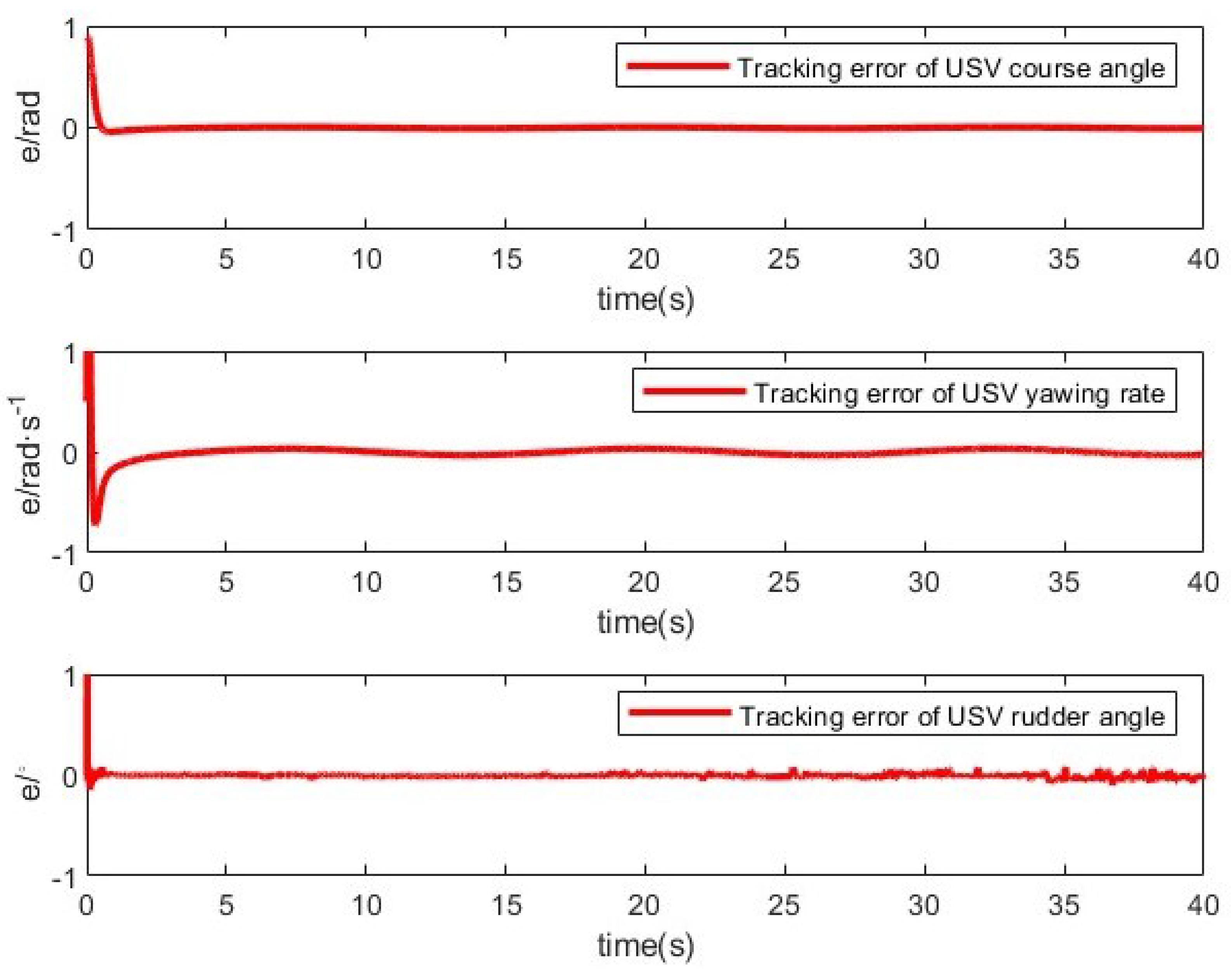
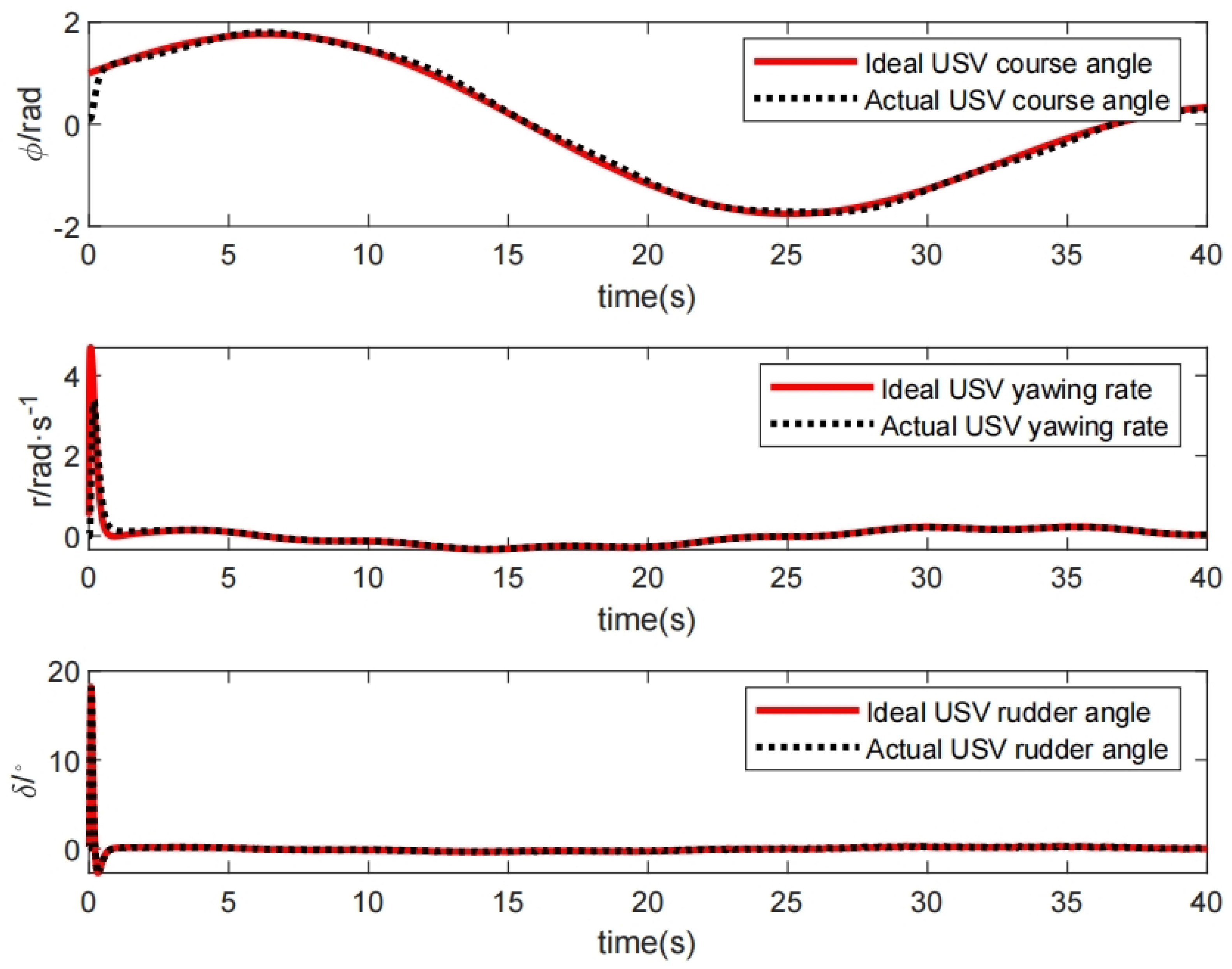
Case 1. In this part, the desired heading command is defined as φ d = cos 0.5 t . Simulation results using the proposed method are shown in Figure 1, Figure 2, Figure 3 and Figure 4. Figure 1 displays the tracking performance of the USV course angle, USV yaw rate, and USV rudder angle. Figure 2 depicts the tracking errors for the USV course angle, yaw rate of USV, and USV rudder angle. The results show that the designed controller can effectively control the heading tracking of the USV and minimize the error. The method quickly minimizes the mistakes to a small set of residuals and performs well. Figure 3 displays the USV control inputs before and after incorporating input quantization and event-triggered mechanisms, where the quantization signal is in the form of a step to reduce the actuator’s actuation frequency. The outcomes of approximating the uncertainty terms in the control system using the fuzzy logic system are displayed in Figure 4. For the simulation, the USV “BlueLetter” from Dalian Maritime University was used, with the following parameters: K = 0.71, T = 0.32, K E = 1, and T E = 2.5. The nonlinear coefficients for the Norrbins motion model are α = 1 and β = 0.001. The quantization parameter was set to o = 8. The following are the controller parameters: c 3 = 25, l = 40, and ρ = 0.02.
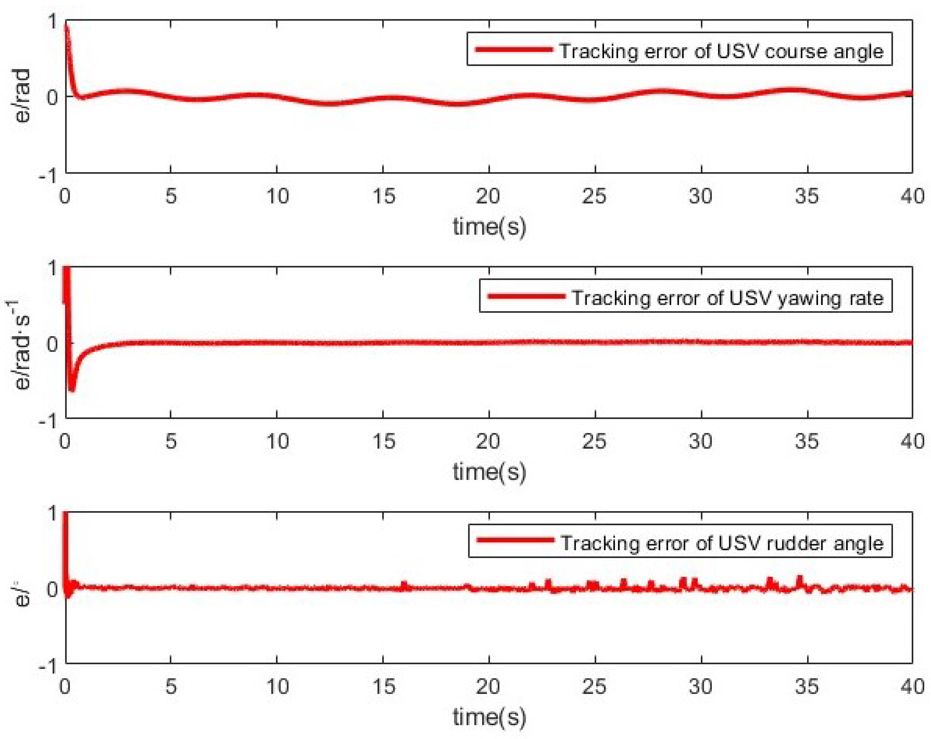
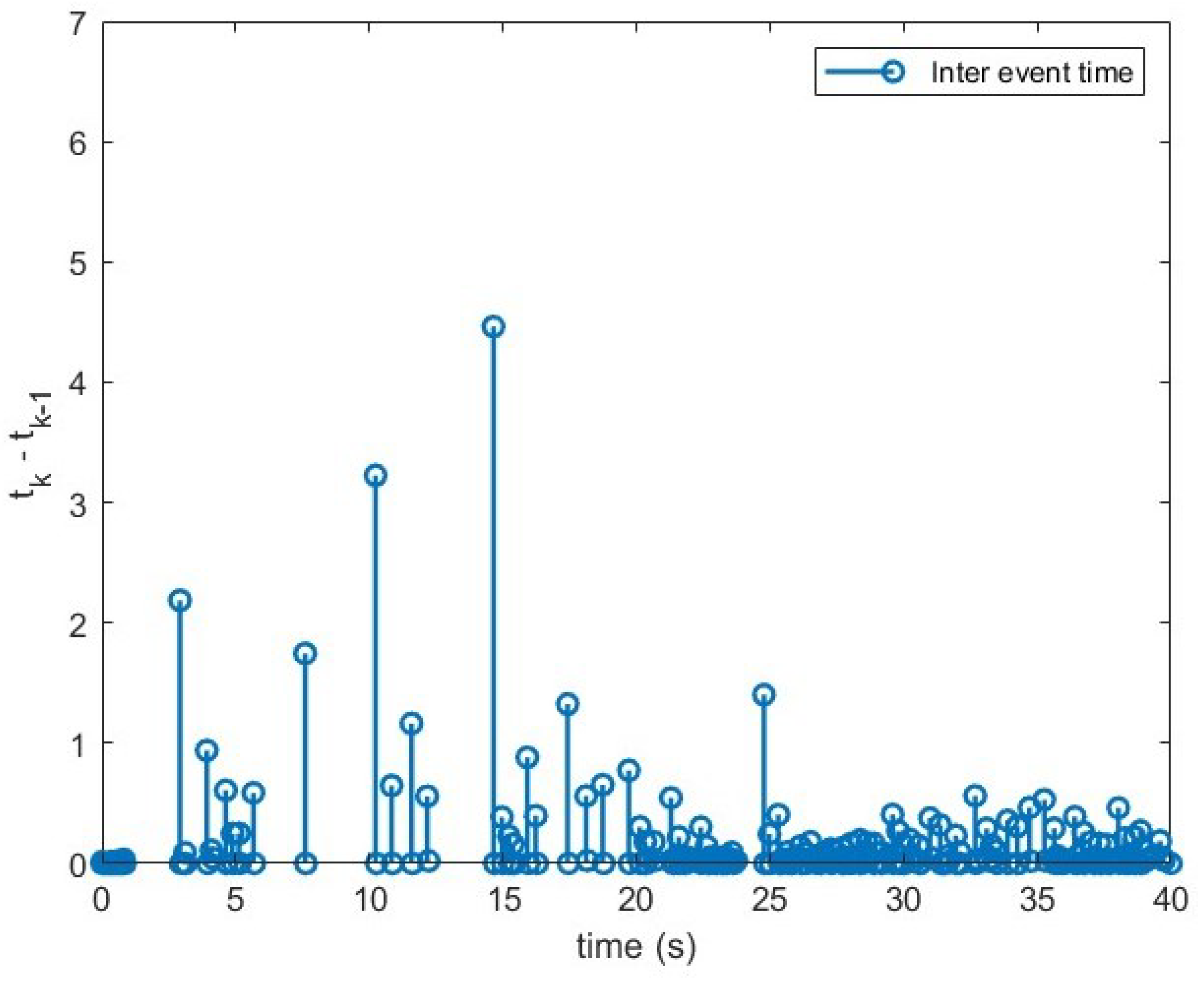
Case 2. This section takes into account that the USV follows the time-varying parametric course φ d = sin(0.2t) + cos(0.1t); the characteristics of the control design are identical to those in case 1. The results are displayed in Figure 5, Figure 6, Figure 7 and Figure 8. Figure 9 shows the time intervals between two continuous sampling moments. The event interval ranges from a minimum of 0.01 s to a maximum of 4.46 s, as shown.

6. Conclusions

This study addresses event-triggered mechanisms and actuator input quantization for course tracking control of unmanned surface vehicles. It takes into account the characteristics of the servo system and describes the quantization process using a linear time-varying model. A fuzzy logic system is employed to approximate the uncertainties in the control system. Subsequently, an event-triggered fuzzy adaptive quantization control law is introduced to reduce the signal transmission load and actuator execution frequency, making it more compatible with the control laws of servo systems in maritime practice. The stability of the closed-loop system is rigorously established through Lyapunov theory, and the simulation results confirm the effectiveness of the proposed control strategy. However, limitations include potential computational bottlenecks for high-frequency trajectories, increased triggering frequency under extreme conditions, and quantization errors that may affect precision.

Author Contributions

Conceptualization, C.J. and J.N.; methodology, Q.W., L.H., and J.N.; software, Q.W. and C.J.; validation, Q.W.; writing—original draft preparation, Q.W. and C.J.; writing—review and editing, Q.W., C.J., J.N., L.H., and Y.Y.; supervision, Q.W. and J.N.; project administration, Q.W. and J.N.; funding acquisition, J.N. All authors have read and agreed to the published version of the manuscript.

Funding

This work was partially funded by the National Natural Science Foundation of China through Grants 51939001, 61976033, and 61803064; the Science and Technology Innovation Funds of Dalian, China, under Grant 2018J11CY022; the Liaoning Revitalization Talents Program, China, under Grant XLYC1908018, XLYC18 07046, the Natural Foundation Guidance Plan Project of Liaoning, China, under Grant 2019-ZD-0151; and the Fundamental Research Funds for the Central Universities, China, under Grant 3132024137.

Institutional Review Board Statement

Not applicable.

Informed Consent Statement

Not applicable.

Data Availability Statement

Data are contained within the article.

Conflicts of Interest

The authors declare no conflicts of interest.

References

  1. Peng, Z.; Gu, N.; Liu, L.; Zhang, B.; Wang, D. Extended state observer design for autonomous surface vehicles using position-yaw measurements. In Proceedings of the 2017 4th International Conference on Information, Cybernetics and Computational Social Systems (ICCSS), Dalian, China, 24–26 July 2017; IEEE: Piscataway, NJ, USA, 2017; pp. 636–641. [Google Scholar]
  2. Jiang, Q.; Li, Y.; Liao, Y.; Miao, Y.; Jiang, W.; Wu, H. Information fusion model-free adaptive control algorithm and unmanned surface vehicle heading control. Appl. Ocean Res. 2019, 90, 101851. [Google Scholar] [CrossRef]
  3. Liu, Y.; Sun, Y.; Hao, L.Y. Nonsingular finite-time heading tracking control of marine vehicles with tracking error constraints. J. Frankl. Inst. 2024, 361, 106734. [Google Scholar] [CrossRef]
  4. Lv, C.; Yu, H.; Hua, Z.; Li, L.; Chi, J. Speed and heading control of an unmanned surface vehicle based on state error PCH principle. Math. Probl. Eng. 2018, 2018, 7371829. [Google Scholar] [CrossRef]
  5. Liu, J.; Huang, L.; Yu, D.; Xu, L.; He, Y. The control method for ship tracking when navigating through narrow and curved sections. Appl. Ocean Res. 2024, 145, 103943. [Google Scholar] [CrossRef]
  6. Chen, X.; Liu, Z.; Zhang, J.; Zhou, D.; Dong, J. Adaptive sliding-mode path following control system of the underactuated USV under the influence of ocean currents. J. Syst. Eng. Electron. 2018, 29, 1271–1283. [Google Scholar] [CrossRef]
  7. Gonzalez-Garcia, A.; Castañeda, H. Guidance and Control Based on Adaptive Sliding Mode Strategy for a USV Subject to Uncertainties. IEEE J. Ocean. Eng. 2021, 46, 1144–1154. [Google Scholar] [CrossRef]
  8. Chen, Z.; Zhang, Y.; Zhang, Y.; Nie, Y.; Tang, J.; Zhu, S. Disturbance-Observer-Based Sliding Mode Control Design for Nonlinear Unmanned Surface Vessel with Uncertainties. IEEE Access 2019, 7, 148522–148530. [Google Scholar] [CrossRef]
  9. Cortes-Vega, D.; Alazki, H.; Rullan-Lara, J.L. Visual odometry-based robust control for an unmanned surface vehicle under waves and currents in a urban waterway. J. Mar. Sci. Eng. 2023, 11, 515. [Google Scholar] [CrossRef]
  10. Huayna-Aguilar, M.M.; Cutipa-Luque, J.C.; Yanyachi, P.R. Robust control and fuzzy logic guidance for an unmanned surface vehicle. Int. J. Adv. Comput. Sci. Appl. 2020, 11, 766–772. [Google Scholar] [CrossRef]
  11. Gonzalez-Garcia, A.; Castañeda, H.; Garrido, L. USV Path-Following Control Based On Deep Reinforcement Learning and Adaptive Control. In Proceedings of the Global Oceans 2020: Singapore—U.S. Gulf Coast, Biloxi, MS, USA, 5–30 October 2020; pp. 1–7. [Google Scholar] [CrossRef]
  12. Liu, Z.; Zhang, Y.; Yuan, C.; Luo, J. Adaptive Path Following Control of Unmanned Surface Vehicles Considering Environmental Disturbances and System Constraints. IEEE Trans. Syst. Man Cybern. Syst. 2021, 51, 339–353. [Google Scholar] [CrossRef]
  13. Song, S.; Park, J.H.; Zhang, B.; Song, X. Event-Triggered Adaptive Practical Fixed-Time Trajectory Tracking Control for Unmanned Surface Vehicle. IEEE Trans. Circuits Syst. II Express Briefs 2021, 68, 436–440. [Google Scholar] [CrossRef]
  14. Mu, D.; Zhao, Y.; Wang, G.; Fan, Y.; Bai, Y. Course control of USV based on fuzzy adaptive guide control. In Proceedings of the 2016 Chinese Control and Decision Conference (CCDC), Yinchuan, China, 28–30 May 2016; pp. 6433–6437. [Google Scholar] [CrossRef]
  15. Wenting, S.; Shaocheng, T. Fuzzy optimal tracking control for nonlinear underactuated unmanned surface vehicles. Ocean. Eng. 2023, 287, 115700. [Google Scholar]
  16. Ahn, J.H.; Rhee, K.P.; You, Y.J. A study on the collision avoidance of a ship using neural networks and fuzzy logic. Appl. Ocean Res. 2012, 37, 162–173. [Google Scholar] [CrossRef]
  17. Wrat, G.; Bhola, M.; Ranjan, P.; Mishra, S.K.; Das, J. Energy saving and Fuzzy-PID position control of electro-hydraulic system by leakage compensation through proportional flow control valve. ISA Trans. 2020, 101, 269–280. [Google Scholar] [CrossRef]
  18. Fang, Y.; Pang, M.; Wang, B. A course control system of unmanned surface vehicle (USV) using back-propagation neural network (BPNN) and artificial bee colony (ABC) algorithm. Procedia Comput. Sci. 2017, 111, 361–366. [Google Scholar] [CrossRef]
  19. Wang, R.; Li, D.; Miao, K. Optimized radial basis function neural network based intelligent control algorithm of unmanned surface vehicles. J. Mar. Sci. Eng. 2020, 8, 210. [Google Scholar] [CrossRef]
  20. Jia, F.; Chen, M. Design of a nonlinear heading control system for ocean going ships based on backstepping technique. J. Coast. Res. 2019, 94, 515–519. [Google Scholar] [CrossRef]
  21. Zhao, Q.; Zhang, H.; Cheng, Z. A Heading Control Strategy Based On Neural Network PID Controller. In Proceedings of the 2020 Chinese Control And Decision Conference (CCDC), Hefei, China, 22–24 August 2020; IEEE: Piscataway, NJ, USA, 2020; pp. 940–944. [Google Scholar]
  22. Mu, D.; Wang, G.; Fan, Y.; Liu, Y.; Jiao, X.; Wang, T.; Li, L. A Novel Heading Control Strategy for Unmanned Surface Vehicle. In Proceedings of the 2021 40th Chinese Control Conference (CCC), Shanghai, China, 26–28 July 2021; IEEE: Piscataway, NJ, USA, 2021; pp. 2756–2760. [Google Scholar]
  23. Fang, X.; Zhou, J.; Wen, G. Location game of multiple unmanned surface vessels with quantized communications. IEEE Trans. Circuits Syst. II Express Briefs 2021, 69, 1322–1326. [Google Scholar] [CrossRef]
  24. Peng, Z.; Gu, N.; Zhang, Y.; Liu, Y.; Wang, D.; Liu, L. Path-guided time-varying formation control with collision avoidance and connectivity preservation of under-actuated autonomous surface vehicles subject to unknown input gains. Ocean. Eng. 2019, 191, 106501. [Google Scholar] [CrossRef]
  25. Hao, L.Y.; Zhao, Z.H. Quantized Sliding Mode Fault-Tolerant Control for Unmanned Marine Vehicles with Thruster Saturation. J. Mar. Sci. Eng. 2023, 11, 309. [Google Scholar] [CrossRef]
  26. Ning, J.; Huang, Y.; Liu, Z.; Li, W.; Yue, X. Adaptive Distributed Heterogeneous Formation Control for UAV-USVs with Input Quantization. J. Mar. Sci. Eng. 2024, 12, 975. [Google Scholar] [CrossRef]
  27. Ren, W.; Xiong, J. Quantized feedback stabilization of nonlinear systems with external disturbance. IEEE Trans. Autom. Control 2018, 63, 3167–3172. [Google Scholar] [CrossRef]
  28. Yang, Y.; Li, J.; Wu, Z.; Liu, X.; Wu, J. Adaptive NN Control of Input-Delayed Stochastic Nonlinear Systems With States and Input Quantization. IEEE Access 2022, 10, 70342–70349. [Google Scholar] [CrossRef]
  29. Zhou, X.; Zhang, Y.; Chen, J.; Zheng, X. A quantized set-membership estimation-based heading control method of unmanned surface vessels under unknown-but-bounded wave-induced disturbances. Asian J. Control 2023, 25, 3105–3118. [Google Scholar] [CrossRef]
  30. Wang, J. Quantized feedback control of discrete-time MIMO linear systems with input and output quantization over finite data rate channels. IEEE Trans. Autom. Control 2022, 68, 6277–6284. [Google Scholar] [CrossRef]
  31. Peng, Z.; Jiang, Y.; Wang, J. Event-triggered dynamic surface control of an underactuated autonomous surface vehicle for target enclosing. IEEE Trans. Ind. Electron. 2020, 68, 3402–3412. [Google Scholar] [CrossRef]
  32. Liu, L.; Zhang, W.; Wang, D.; Peng, Z. Event-triggered extended state observers design for dynamic positioning vessels subject to unknown sea loads. Ocean Eng. 2020, 209, 107242. [Google Scholar] [CrossRef]
  33. Ning, J.; Ma, Y.; Li, T.; Chen, C.P.; Tong, S. Event-triggered based trajectory tracking control of under-actuated unmanned surface vehicle with state and input quantization. IEEE Trans. Intell. Veh. 2023, 9, 3127–3139. [Google Scholar] [CrossRef]
  34. Zhou, Z.; Rother, C.; Chen, J. Event-triggered model predictive control for autonomous vehicle path tracking: Validation using CARLA simulator. IEEE Trans. Intell. Veh. 2023, 8, 3547–3555. [Google Scholar] [CrossRef]
  35. Chen, Y.; Zhao, H.; Xu, D.; Yu, H. Event-triggered model-free adaptive sliding-mode heading control for unmanned surface vehicles under DoS attacks. Appl. Ocean Res. 2024, 153, 104203. [Google Scholar] [CrossRef]
  36. Ning, J.; Wang, Y.; Liu, L.; Li, T. Disturbance observer based adaptive heading control for unmanned marine vehicles with event-triggered and input quantization. Int. J. Robust Nonlinear Control 2024, 34, 11469–11486. [Google Scholar] [CrossRef]
  37. Deng, Y.; Zhang, X. Event-triggered composite adaptive fuzzy output-feedback control for path following of autonomous surface vessels. IEEE Trans. Fuzzy Syst. 2020, 29, 2701–2713. [Google Scholar] [CrossRef]
  38. Li, A.; Shen, Z.; Bi, H.; Yu, H. Event-triggered error-constrained switching guidance-based marine surface vessel path-following control and collision avoidance. Proc. Inst. Mech. Eng. Part I J. Syst. Control Eng. 2024, 238, 1050–1066. [Google Scholar] [CrossRef]
  39. Chen, X.; Liu, Z.; Hu, H.; Wang, L.; Dong, J. Backstepping adaptive sliding mode control for the USV course tracking system. In Proceedings of the 2017 9th International Conference on Advanced Infocomm Technology (ICAIT), Chengdu, China, 22–24 November 2017; IEEE: Piscataway, NJ, USA, 2017; pp. 265–269. [Google Scholar]
  40. Jiang, Q.; Liao, Y.; Li, Y.; Fan, J.; Miao, Y. Heading control of unmanned surface vehicle with variable output constraint model-free adaptive control algorithm. IEEE Access 2019, 7, 131008–131018. [Google Scholar] [CrossRef]
  41. Ge, Y.; Zhong, L.; Qiang, Z.J. Research on usv heading control method based on kalman filter sliding mode control. In Proceedings of the 2020 Chinese Control And Decision Conference (CCDC), Hefei, China, 22–24 August 2020; IEEE: Piscataway, NJ, USA, 2020; pp. 1547–1551. [Google Scholar]
  42. Hao, L.Y.; Yang, X.; Zhang, Y.Q.; Atajan, H.; Liu, Y. Fault-tolerant control of unmanned marine vehicles with unknown parametric dynamics via integral sliding mode output feedback control. Asian J. Control 2024, 27, 840–851. [Google Scholar] [CrossRef]
  43. Wang, C.; Xie, S.; Chen, H.; Peng, Y.; Zhang, D. Course Control of Unmanned Surface Vehicle Based on Fuzzy Sliding Mode. In Proceedings of the 2019 IEEE International Conference on Advanced Robotics and its Social Impacts (ARSO), Beijing, China, 31 October–2 November 2019; IEEE: Piscataway, NJ, USA, 2019; pp. 287–290. [Google Scholar]
  44. Bai, Y.; Zhao, Y.; Fan, Y. The unmanned surface vehicle course tracking control with input saturation. In Proceedings of the 2017 36th Chinese Control Conference (CCC), Dalian, China, 26–28 July 2017; IEEE: Piscataway, NJ, USA, 2017; pp. 40–43. [Google Scholar]
  45. Yoo, S.J.; Park, B.S. Guaranteed performance design for distributed bounded containment control of networked uncertain underactuated surface vessels. J. Frankl. Inst. 2017, 354, 1584–1602. [Google Scholar] [CrossRef]
  46. Fossen, T.I.; Paulsen, M. Adaptive feedback linearization applied to steering of ships. Model. Identif. Control 1993, 14, 229–237. [Google Scholar] [CrossRef]
  47. Kim, Y.H.; Ahn, S.C.; Kwon, W.H. Computational complexity of general fuzzy logic control and its simplification for a loop controller. Fuzzy Sets Syst. 2000, 111, 215–224. [Google Scholar] [CrossRef]
  48. Qin, H.; Li, C.; Sun, Y. Adaptive neural network-based fault-tolerant trajectory-tracking control of unmanned surface vessels with input saturation and error constraints. IET Intell. Transp. Syst. 2020, 14, 356–363. [Google Scholar] [CrossRef]
  49. Ma, Y.; Li, W.; Ning, J.; Liu, L. Disturbance observer based adaptive heading control for unmanned surface vehicle with event-triggered and signal quantization. Int. J. Adapt. Control Signal Process. 2024, 38, 3195–3212. [Google Scholar] [CrossRef]
  50. Liu, Y.; Chen, Y. Dynamic memory event-triggered adaptive control for a class of strict-feedback nonlinear systems. IEEE Trans. Circuits Syst. II Express Briefs 2022, 69, 3470–3474. [Google Scholar] [CrossRef]
Figure 1. USV tracking results.
Actuators 14 00130 g001
Figure 2. USV tracking error curve.
Actuators 14 00130 g002
Figure 3. USV control input.
Actuators 14 00130 g003
Figure 4. Results of fuzzy approximate.
Actuators 14 00130 g004
Figure 5. USV tracking result.
Actuators 14 00130 g005
Figure 6. USV tracking error curve.
Actuators 14 00130 g006
Figure 7. USV control input.
Actuators 14 00130 g007
Figure 8. Results of fuzzy approximate.
Actuators 14 00130 g008
Figure 9. Time interval between the two adjacent event-triggered sampling points.
Actuators 14 00130 g009
Disclaimer/Publisher’s Note: The statements, opinions and data contained in all publications are solely those of the individual author(s) and contributor(s) and not of MDPI and/or the editor(s). MDPI and/or the editor(s) disclaim responsibility for any injury to people or property resulting from any ideas, methods, instructions or products referred to in the content.