
Speed and Energy Efficiency of a Fish Robot Featuring Exponential Patterns of Control


Abstract
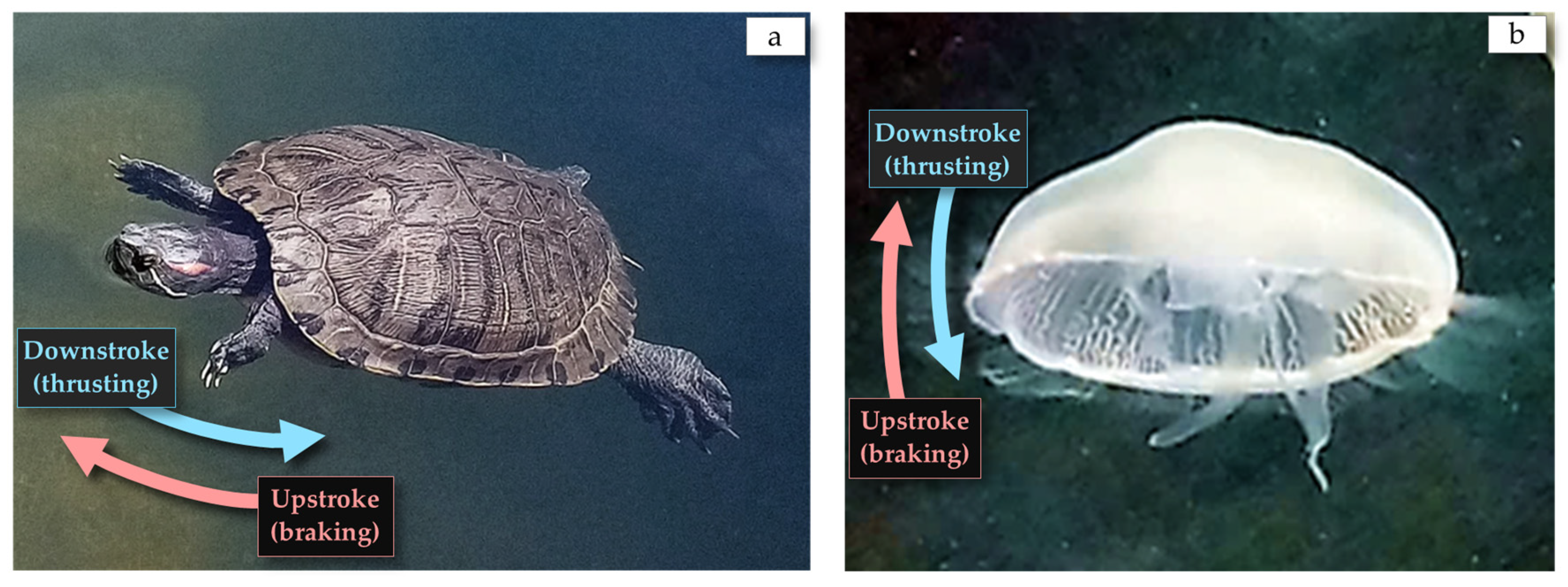
1. Introduction
2. Materials and Methods
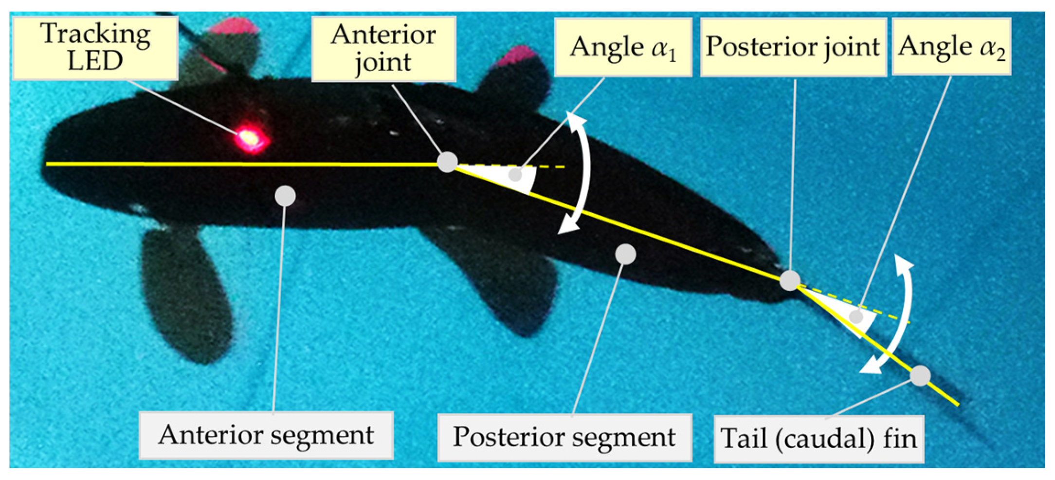
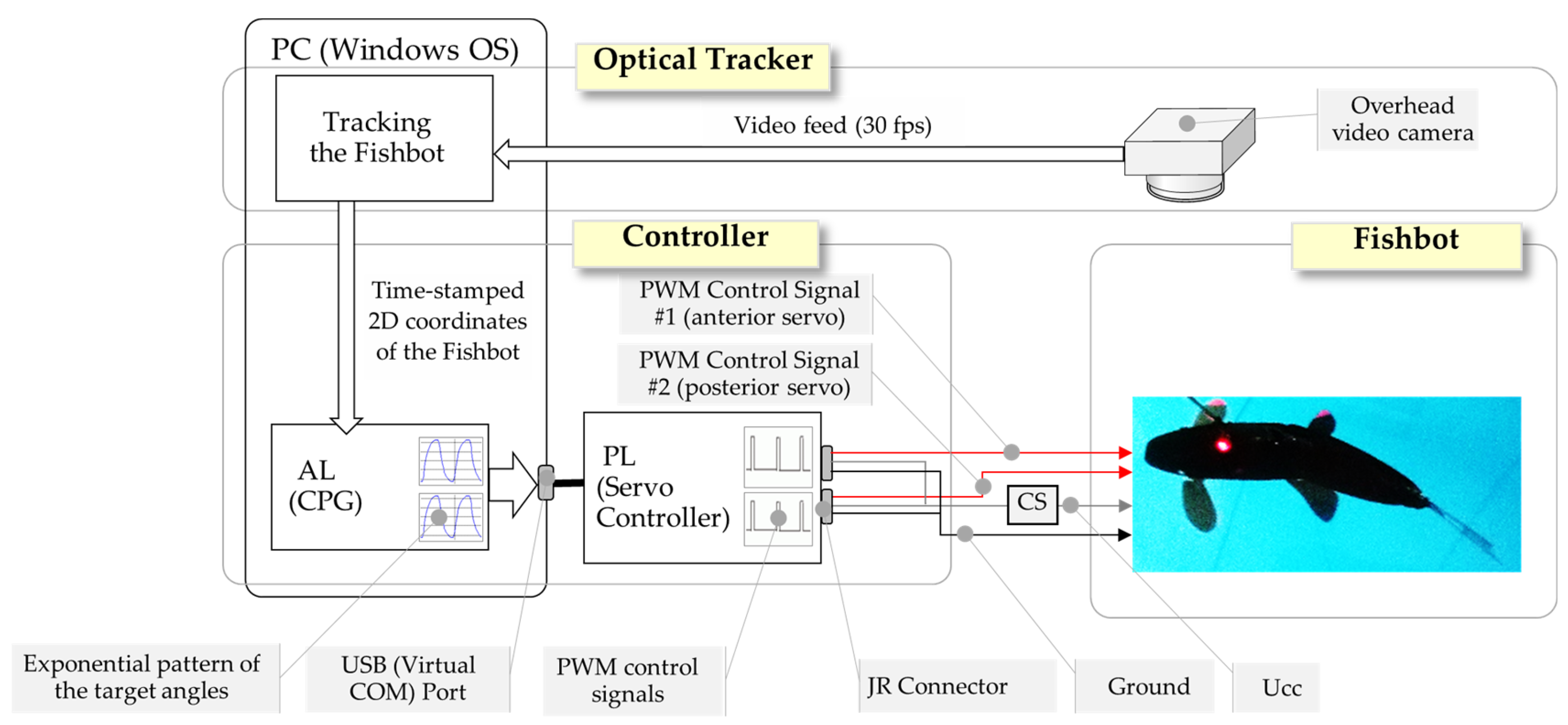
2.1. The Design and Control of the Fishbot
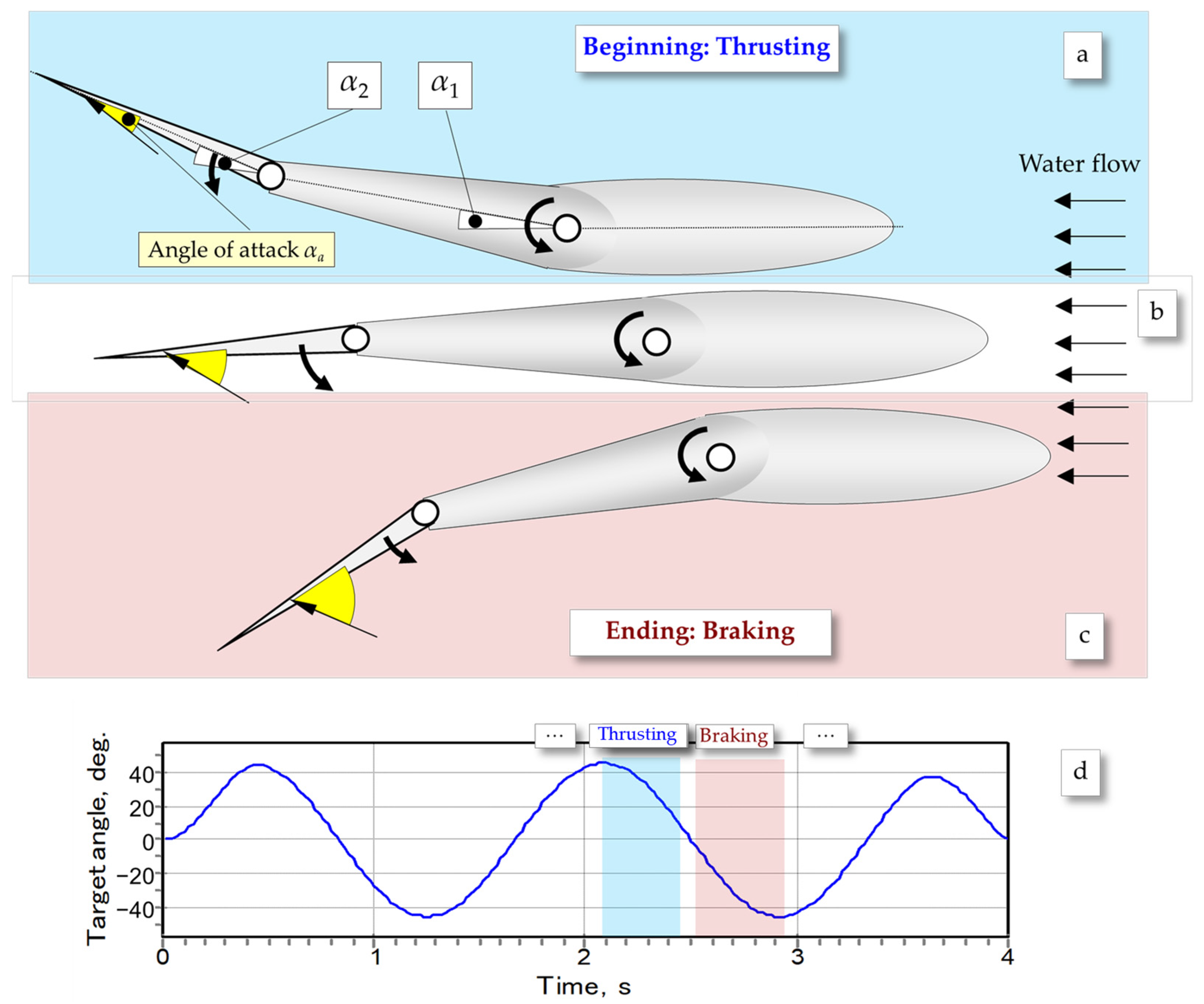
2.2. Analysis of Undulation
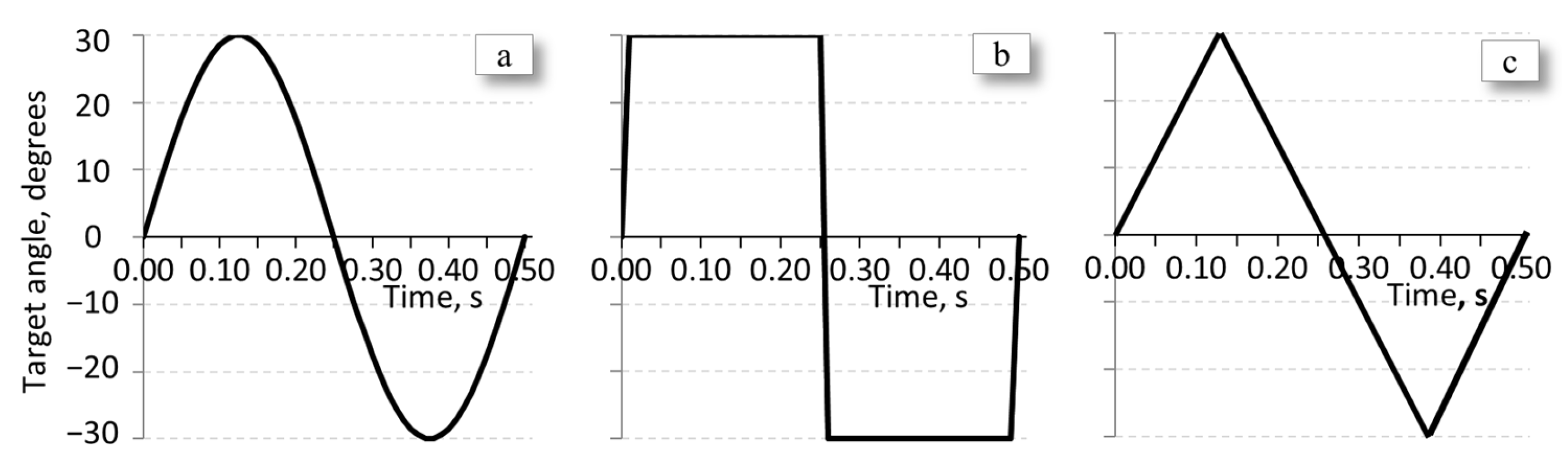
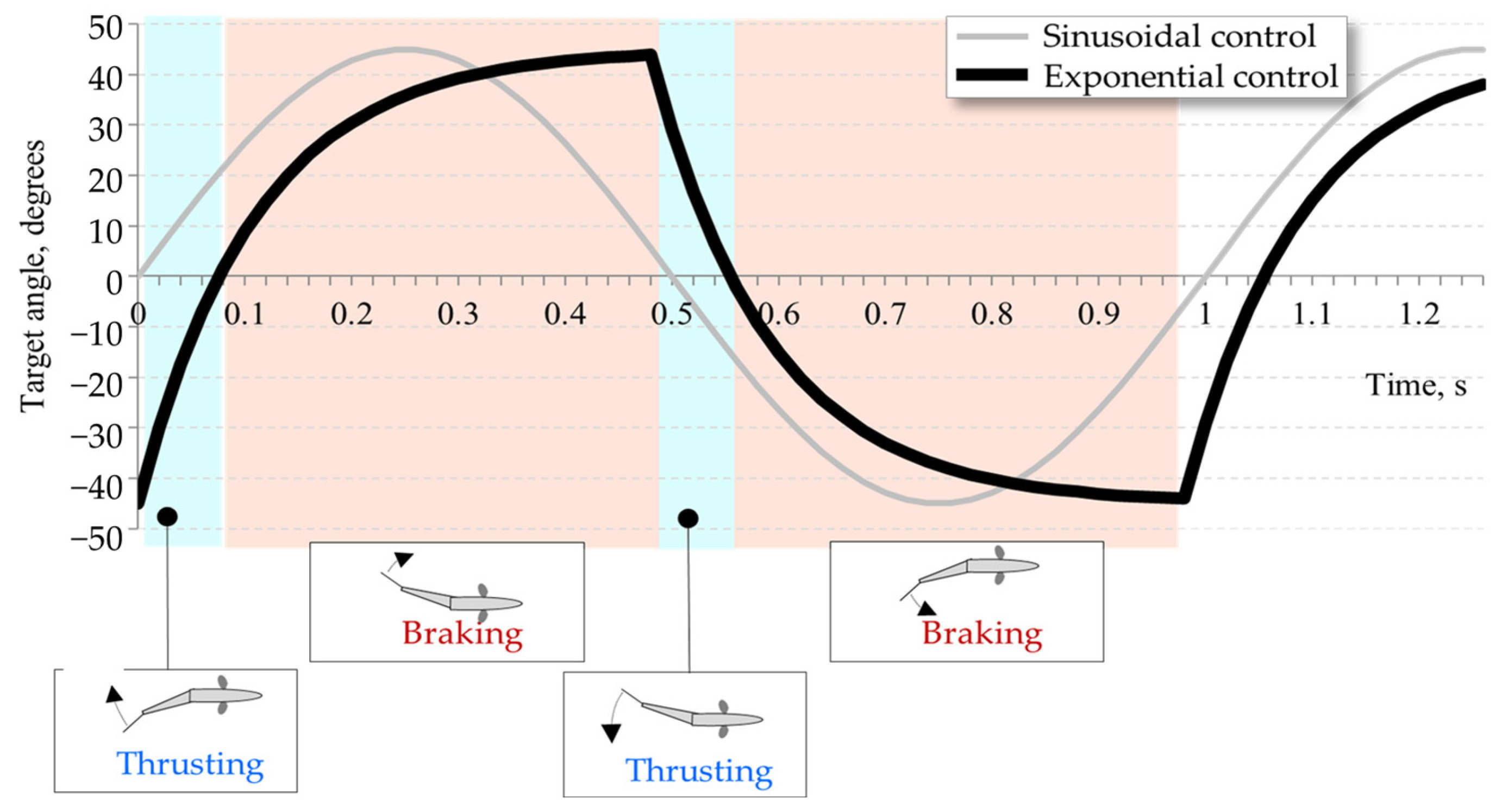
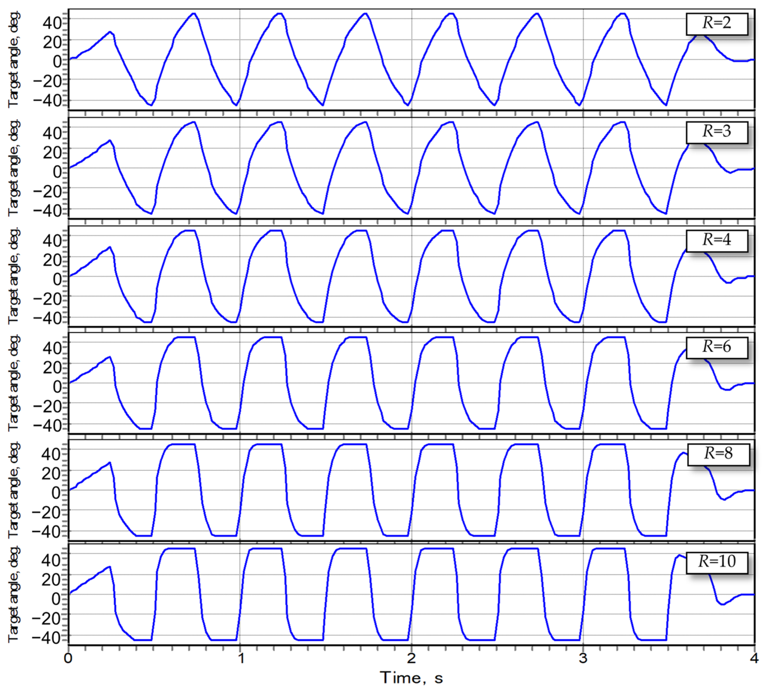
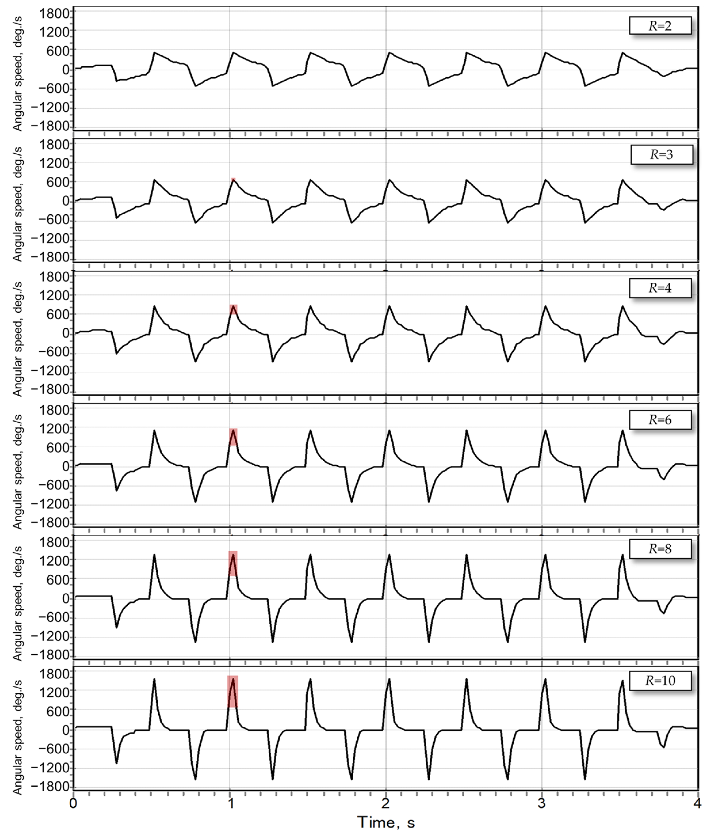
2.3. The Concept of the Exponential Control of the Fishbot
- While an increased ratio TB/TT is sought, the sum TB + TT should be equal to half of the period of undulation;
- An increased ratio TB/TT implies that the average derivative (i.e., gradient) of the function of the target turning angle of servo motors during the thrusting phase should be higher than that of the braking phase;
- The transition between the two (thrusting and braking) phases should be smooth, with the higher instant derivative of the function of the target turning angle of servo motors during the thrusting phase gradually approaching the lower values pertinent to the braking phase of undulation;
- The target turning angle of servo motors of both phases of undulation should (preferably) be expressed by the same (monotonous) function.
3. Experimental Results
3.1. Experimental Setup
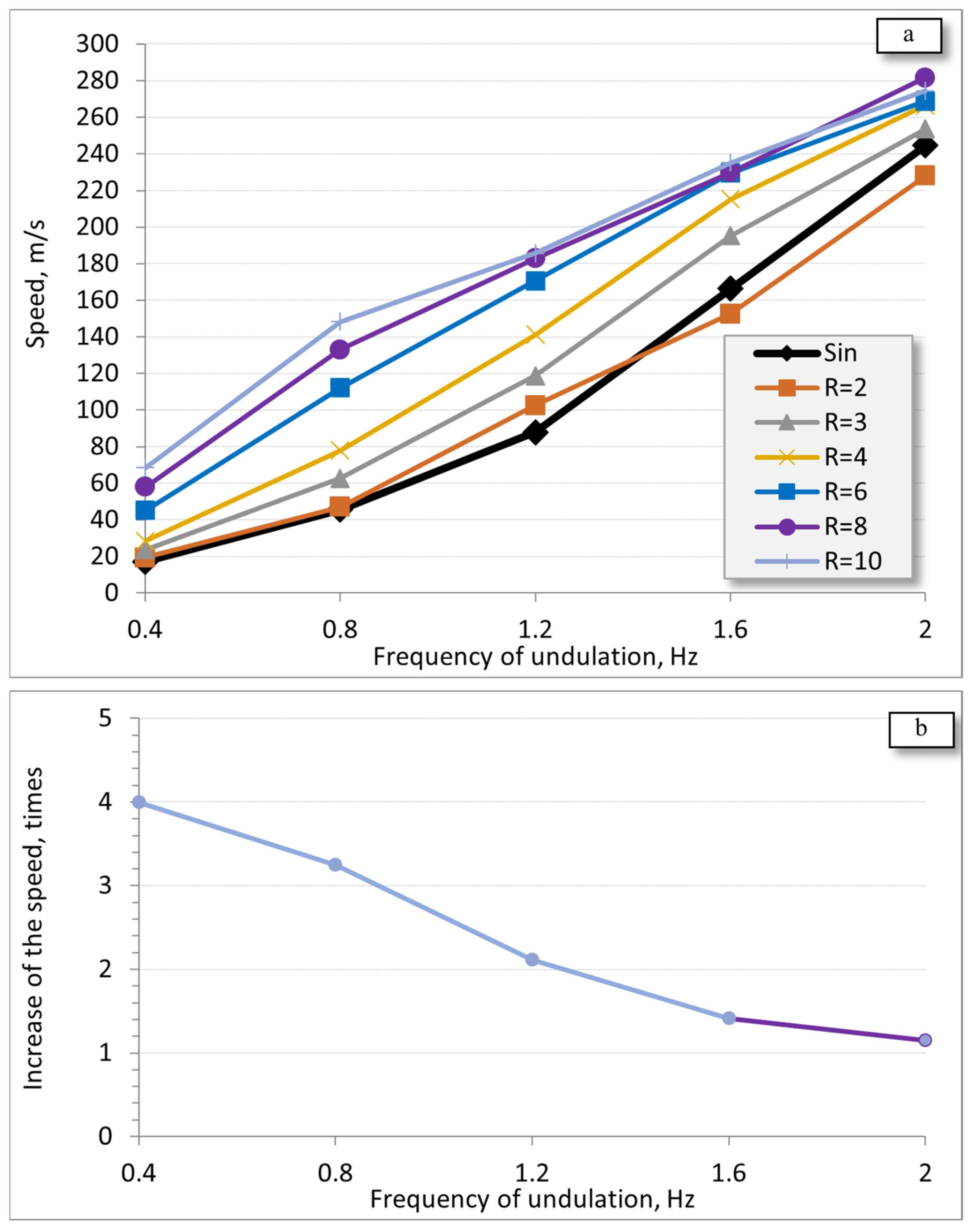
3.2. Swimming Speed
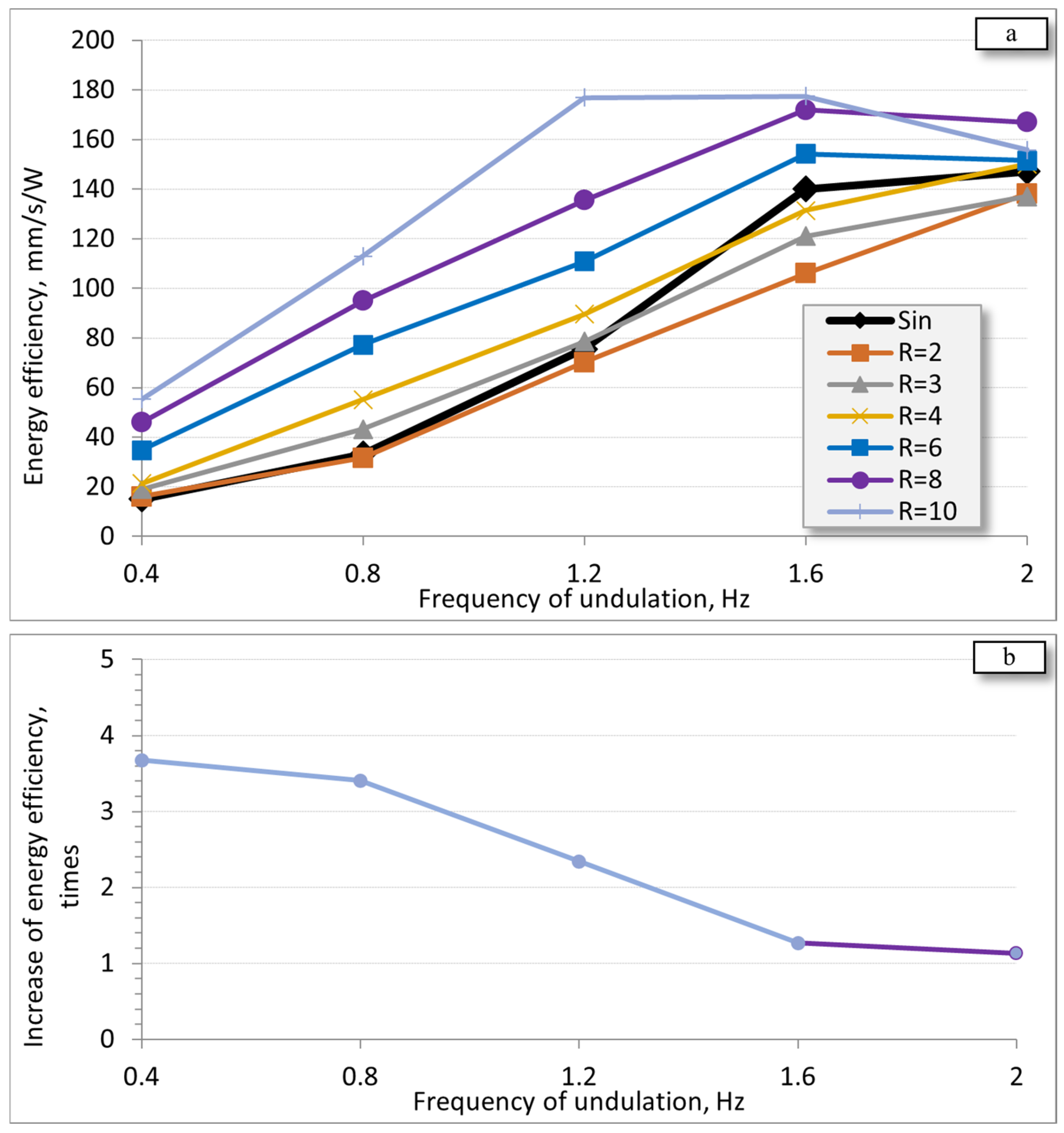
3.3. Energy Efficiency
4. Discussion
5. Conclusions
Funding
Data Availability Statement
Conflicts of Interest
References
- Breder, C.M.; Breder, C.M. The locomotion of fishes. Zool. Sci. Contrib. N. Y. Zool. Soc. 1926, 4, 159–297. [Google Scholar] [CrossRef]
- Fish, F. Swimming Strategies for Energy Economy. In Fish Locomotion; Eco-Ethological Perspect; CRC Press: Boca Raton, FL, USA, 2010. [Google Scholar] [CrossRef]
- Mannam, N.P.B.; Alam, M.M.; Krishnankutty, P. Review of biomimetic flexible flapping foil propulsion systems on different planetary bodies. Results Eng. 2020, 8, 100183. [Google Scholar] [CrossRef]
- Tanev, I. Fish Robot: Design, Control and Evolution of Undulatory Swimming Gaits. Technical Report, 2021; 33p. Available online: http://isd-si.doshisha.ac.jp/itanev/TR/TR_20210716_Fishbot.pdf (accessed on 24 December 2024).
- Vo, T.Q.; Kim, H.S.; Lee, B.R. Smooth gait optimization of a fish robot using the genetic-hill climbing algorithm. Robotica 2012, 30, 257–278. [Google Scholar] [CrossRef]
- Roper, D. Energy Based Control System Designs for Underactuated Robot Fish Propulsion. Ph.D. Thesis, University of Plymouth, Plymouth, UK, 2013. [Google Scholar] [CrossRef]
- Wang, W.; Guo, J.; Wang, Z.; Xie, G. Neural controller for swimming modes and gait transition on an ostraciiform fish robot. In Proceedings of the 2013 IEEE/ASME International Conference on Advanced Intelligent Mechatronics, Wollongong, NSW, Australia, 9–12 July 2013; pp. 1564–1569. [Google Scholar] [CrossRef]
- Wang, W.; Gu, D.; Xie, G. Autonomous Optimization of Swimming Gait in a Fish Robot with Multiple Onboard Sensors. IEEE Trans. Syst. Man Cybern. Syst. 2019, 49, 891–903. [Google Scholar] [CrossRef]
- Zhu, J.; White, C.; Wainwright, D.K.; Di Santo, V.; Lauder, G.V.; Bart-Smith, H. Tuna robotics: A high-frequency experimental platform exploring the performance space of swimming fishes. Sci. Robot. 2019, 4, eaax4615. [Google Scholar] [CrossRef] [PubMed]
- Iida, F.; Pfeifer, R.; Seyfarth, A. AI in Locomotion: Challenges and Perspectives of Underactuated Robots. In 50 Years of Artificial Intelligence: Essays Dedicated to the 50th Anniversary of Artificial Intelligence; Lungarella, M., Iida, F., Bongard, J., Pfeifer, R., Eds.; Lecture Notes in Computer Science; Springer: Berlin, Heidelberg, 2007; pp. 134–143. [Google Scholar] [CrossRef]
- Romano, D.; Wahi, A.; Miraglia, M.; Stefanini, C. Development of a Novel Underactuated Robotic Fish with Magnetic Transmission System. Machines 2022, 10, 755. [Google Scholar] [CrossRef]
- Takada, Y.; Nakanishi, Y.; Araki, R.; Nonogaki, M.; Wakisaka, T. Effect of Material and Thickness about Tail Fins on Propulsive Performance of a Small Fish Robot. J. Aero Aqua Bio-Mech. 2010, 1, 51–56. [Google Scholar] [CrossRef]
- Heinen, Y.; Tanev, I.; Kimura, T. The Effect of a Limited Underactuated Posterior Joint on the Speed and Energy Efficiency of a Fish Robot. Appl. Sci. 2024, 14, 5010. [Google Scholar] [CrossRef]
- Di Santo, V.; Goerig, E.; Wainwright, D.K.; Lauder, G.V. Convergence of undulatory swimming kinematics across a diversity of fishes. Proc. Natl. Acad. Sci. USA 2021, 118, e2113206118. [Google Scholar] [CrossRef] [PubMed]
- Komoto, T.; Tanev, I.; Shimohara, K. Evolving the Thrust of Undulatory Swimming Gaits of Fish Robot. In Proceedings of the 27th Symposium on Artificial Life and Robotics (AROB-ISBC-SWARM 2022), Beppu, Japan, 25 January 2022; p. 6. [Google Scholar]
- Sancho, M.A.; Tanev, I.; Shimohara, K. Fitness Lookup Table Reduces the Runtime of Evolution of Swimming Gaits of Fish Robot. In Proceedings of the 28th Symposium on Artificial Life and Robotics (AROB-ISBC-SWARM 2023), Beppu, Japan, 25 January 2023; p. 6. [Google Scholar]
- Čech, M.; Jarolím, O.; Kubecka, J.; Vašek, M.; Peterka, J.; Matěna, J. Sinusoidal swimming in fishes: Using hydroacoustics, underwater camera and direct sampling techniques to understand peculiar fish behavior. In Proceedings of the Modern Problems of Aquatic Ecology—4th International Scientific Conference to Commemorate Prof. G.G. Winberg, St. Petersburg, Russia, 11–15 October 2010. [Google Scholar] [CrossRef]
- Van Buren, T.; Floryan, D.; Quinn, D.; Smits, A. Nonsinusoidal gaits for unsteady propulsion. Phys. Rev. Fluids 2017, 2, 053101. [Google Scholar] [CrossRef]
- Bale, R.; Shirgaonkar, A.A.; Neveln, I.D.; Bhalla, A.P.S.; MacIver, M.A.; Patankar, N.A. Separability of Drag and Thrust in Undulatory Animals and Machines. Sci. Rep. 2014, 4, 7329. [Google Scholar] [CrossRef] [PubMed]
- MacDonald, J. What Makes Fish Swim Fast. JSTOR: Digital Library for Scholars, Researchers, and Students, October 3, 2017. Available online: https://daily.jstor.org/what-makes-fish-swim-fast/ (accessed on 23 December 2024).
- Arakeri, J.H. Fluid Mechanics of Fish Swimming: Lift-based Propulsion. Resonance 2009, 14, 32–46. Available online: https://www.ias.ac.in/article/fulltext/reso/014/01/0032-0046 (accessed on 24 December 2024). [CrossRef]
- Webb, P.W. Simple Physical Principles and Vertebrate Aquatic Locomotion. Am. Zool. 1988, 28, 709–725. [Google Scholar] [CrossRef]
- Pololu Robotics and Electronics. Micro Maestro 6-Channel USB Servo Controller. Available online: https://www.pololu.com/product/1350 (accessed on 23 December 2024).
- Pololu Robotics and Electronics. ACS724LLCTR-2P5AB Current Sensor Carrier. Available online: https://www.pololu.com/product/4040 (accessed on 23 December 2024).
- Huizhou AGF-RC Electronic Technology Company, A20CLS Programmable Micro Servo. Available online: https://www.agfrc.com/index.php?id=2429 (accessed on 26 January 2025).


| R = TB/TT | kps(APS = kps × ASM) | kτ(τ = kτ × THP) |
|---|---|---|
| 2 | 1.618 | 0.693 |
| 3 | 1.192 | 0.410 |
| 4 | 1.078 | 0.305 |
| 6 | 1.017 | 0.209 |
| 8 | 1.004 | 0.161 |
| 10 | 1.001 | 0.131 |
Disclaimer/Publisher’s Note: The statements, opinions and data contained in all publications are solely those of the individual author(s) and contributor(s) and not of MDPI and/or the editor(s). MDPI and/or the editor(s) disclaim responsibility for any injury to people or property resulting from any ideas, methods, instructions or products referred to in the content. |
© 2025 by the author. Licensee MDPI, Basel, Switzerland. This article is an open access article distributed under the terms and conditions of the Creative Commons Attribution (CC BY) license (https://creativecommons.org/licenses/by/4.0/).
Share and Cite
Tanev, I. Speed and Energy Efficiency of a Fish Robot Featuring Exponential Patterns of Control. Actuators 2025, 14, 119. https://doi.org/10.3390/act14030119
Tanev I. Speed and Energy Efficiency of a Fish Robot Featuring Exponential Patterns of Control. Actuators. 2025; 14(3):119. https://doi.org/10.3390/act14030119
Chicago/Turabian StyleTanev, Ivan. 2025. "Speed and Energy Efficiency of a Fish Robot Featuring Exponential Patterns of Control" Actuators 14, no. 3: 119. https://doi.org/10.3390/act14030119
APA StyleTanev, I. (2025). Speed and Energy Efficiency of a Fish Robot Featuring Exponential Patterns of Control. Actuators, 14(3), 119. https://doi.org/10.3390/act14030119