1. Introduction
Over the past century, rotary-wing aircraft (such as helicopters) and fixed-wing aircraft have dominated as the primary aviation lift-generation technologies. While effective, both have inherent limitations in specific scenarios. Readers are encouraged to consult these references for a detailed historical overview and technical discussion of the dominance and limitations of fixed-wing and rotary-wing aircraft [
1,
2,
3,
4]. A less common but promising alternative is the flapping wing, which mimics the wing motion of birds and insects. However, flapping wings have seen limited use in practical aviation applications due to the complexities involved in the design, as well as the need for extensive prototype testing and validation.
In recent decades, there has been significant interest in developing hybrid aircraft that combine the benefits of both fixed and rotary-wing systems to enhance overall performance and flexibility. For more insights into the significant interest and advancements in hybrid aircraft, especially those that integrate fixed and rotary-wing systems, readers can refer to these references [
5,
6,
7]. These hybrid vehicles often utilize rotary wings or small ducted fans for vertical take-off and landing (VTOL) while transitioning to fixed wings for forward or horizontal flight to achieve higher speed and efficiency. Such designs aim to overcome the constraints faced by conventional rotorcraft, including limited speed and range, by leveraging the aerodynamic advantages of fixed wings during cruising flight.
Despite their potential, hybrid VTOL aircraft have not yet achieved widespread acceptance in commercial or military aviation. A primary reason for this is their reliance on rotary wings or small fans for VTOL, which can inherit several issues associated with traditional rotorcraft. These issues include mechanical complexity, high noise levels, susceptibility to aerodynamic inefficiencies, and safety concerns. Additionally, transitioning from VTOL to fixed-wing flight presents a significant engineering challenge, requiring seamless changes in aerodynamic forces and control dynamics. As a result, hybrid vehicles often struggle to achieve stable, efficient flight across all phases of operation. Further readings on the challenges, flight dynamics, control, and review of hybrid VTOL vehicles can be found in the following references [
7,
8,
9,
10].
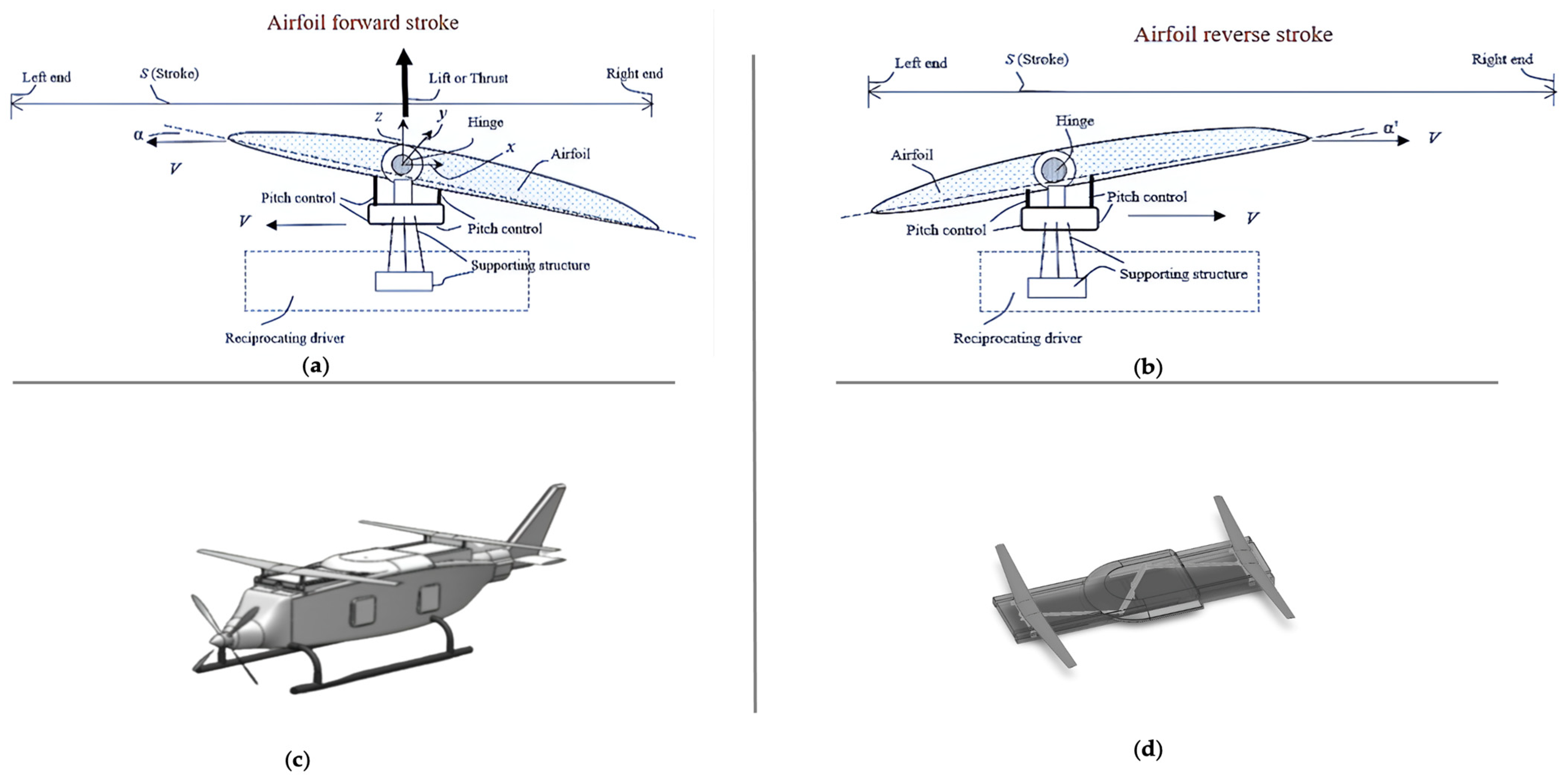
This study examines the reciprocating airfoil (RA) or reciprocating wing (RW) as an innovative solution for tackling challenges in VTOL applications. The RA wing concept combines the features of fixed wings with a reciprocating motion mechanism to create lift without the use of traditional rotors or fans. The RA wing is designed to facilitate a smoother transition between VTOL and fixed-wing modes by employing a fixed-wing configuration capable of generating lift through reciprocating movement. This approach has the potential to resolve many issues faced by conventional hybrid VTOL designs, such as reduced noise, decreased mechanical complexity, and improved aerodynamic efficiency. The RA wing could signify a major advancement in the design of next-generation UAVs and unconventional VTOL aircraft, presenting a promising alternative to traditional lift-generation methods. The subsequent sections of this study will provide a brief overview of UAVs, discuss the initial RA/RW design and FEA insights, explore the topology optimization of an aircraft wing and the RA, and present key results.
Section 5 and
Section 6 will discuss their implications, advanced mobility technologies, and potential directions for future research.
A Brief Review of UAVs
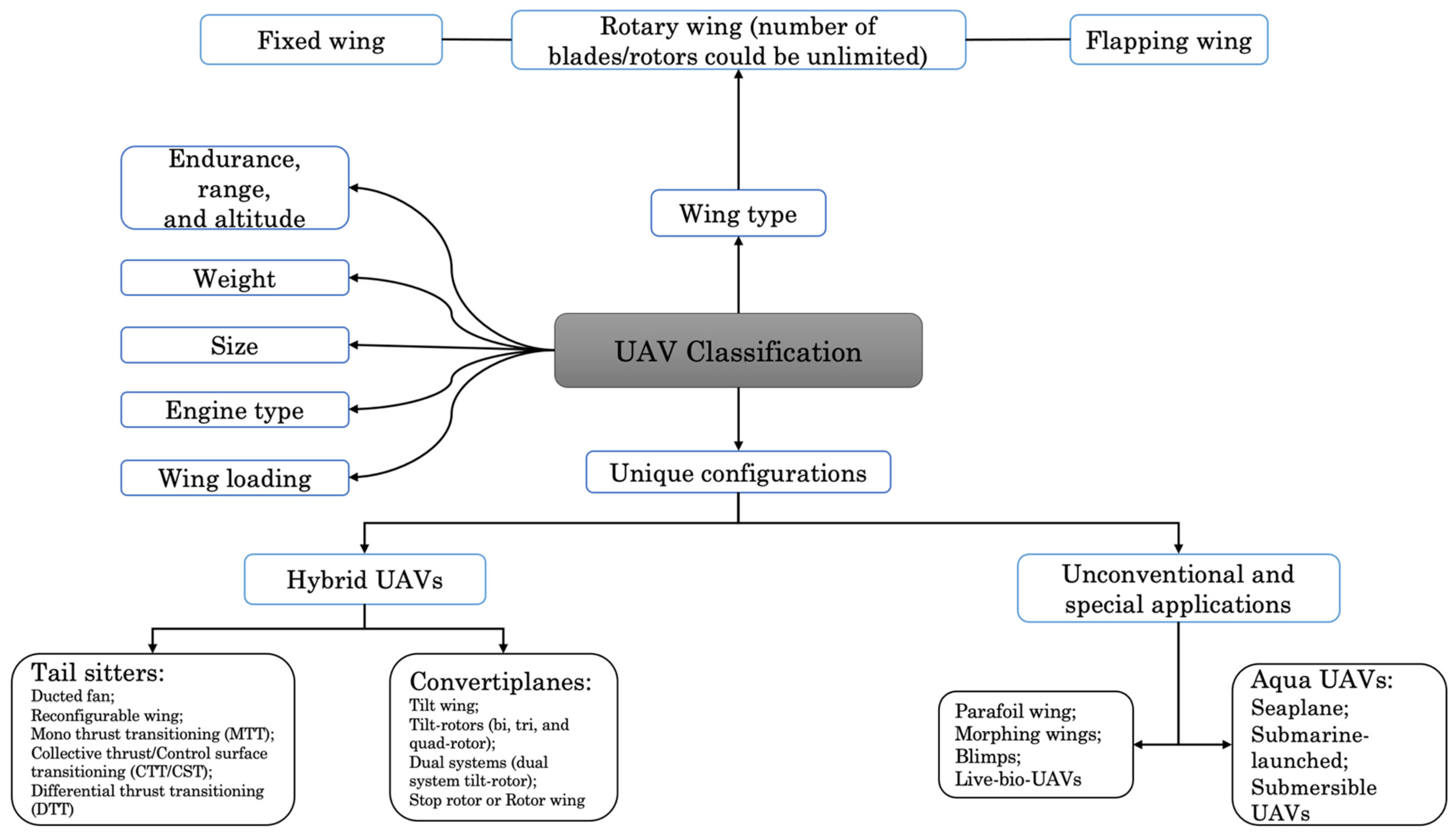
UAVs can be categorized into various classifications that grow as new innovations are introduced. This is attributed to the advancements and creativity behind more distinct types of UAVs. They can be classified based on their wing type, size, weight, engine type, wing loading, endurance/range/altitude, and specific configurations. The classification based on wing type is divided into three fundamental types of wings. They are the fixed wing, rotary wing, and flapping wing. Examples of fixed-wing UAVs are the Airbus Zephyr UAV [
11], the Northrop Grumman RQ-4 Global Hawk [
12], and the IAI Heron TP Medium-Altitude Long Endurance (MALE) UAV [
13]. Other examples of fixed-wing unoccupied combat aerial vehicles (UCAVs) include the Phantom Ray [
14], Boeing MQ-28A Ghost Bat, and the General Atomics MQ-9 Reaper. Rotary wings can be subcategorized into single-rotor/monocopters (one blade/rotor) [
15,
16,
17], twin-rotors/bicopters (two blade/rotors) [
18,
19,
20], and multi-rotors/multicopters (greater than three blade/rotors) [
21,
22]. The number of rotors for rotary wing vehicles can be unlimited based on the intended application. Ornithopter UAVs primarily utilize a flapping mechanism to move their wings and generate lift. Examples of flapping wings include the Nano Air Vehicle (NAV) [
23], the SmartBird [
24,
25], and the hummingbird robot prototype [
26]. Flapping wings are generally not utilized, as their development and widespread applicability to the aerospace market have yet to be actualized.
A UAV’s maximum flight time (referred to as endurance, usually measured in hours), reach, and height on one load of fuel or charge (referred to as the range measured in kilometers or miles) is one of the ways UAVs can be classified, as shown in
Figure 1. UAVs are also classified according to their weight (from nano to super heavy), wing loading (aircraft mass (kg) divided by wing area (m
2) in kg/m
2), size (from ultra-small, with a wing span of 0.15 m, to large UAVs, with a wing span more significant than 35 m), and engine type (reciprocating, electric, turboprop, etc.).
The unique configurations of UAV classification are due to the birth of novel and hybrid forms of UAVs that are modified to produce better performance. As shown in
Figure 1, the unique configurations can be grouped into hybrid, unconventional, and special applications.
Hybrid UAVs combine the merits of fixed and rotary wings and are grouped into tail sitters and convertiplanes. The various types of tail sitters are the ducted fan [
27,
28,
29]; reconfigurable wing [
30]; and those based on a transition mechanism such as the mono thrust transitioning (MTT) [
31], collective thrust or control surface transitioning (CTT/CST) [
32], and differential thrust transitioning (DTT) [
33]. Conversely, convertiplanes are the tilt-wing [
34,
35,
36,
37], tilt-rotors [
38,
39], dual systems [
40,
41], and the stop-rotor or rotor wing [
42,
43,
44]. Examples of unconventional UAV configurations are aqua UAVs [
45], parafoil wings [
46], morphing wings [
47,
48,
49], blimps [
50], controlled insects [
51], and live-bio UAVs [
52].
Figure 1 displays an overview of various UAV classifications.
3. Initial FEA Insights: A Precursor to Optimized Structural Design
The finite element analysis (FEA) was performed in ANSYS mechanical, where the material selection, geometry importation, meshing, and simulation boundary conditions were set up. The lift and drag forces at maximum velocity were obtained from the 3D CFD simulation performed in previous studies [
57]. The CFD study validated the lift-generation mechanism of the reciprocating wing under various flight conditions. The simulations utilized the Realizable k-ε turbulence model with enhanced wall functions to handle low Reynolds number situations. At take-off, the lift coefficient (C
L) was approximately 2.0 at a Reynolds number of 2 × 10
5 and at cruise speeds of 60 m/s (216 km/h). The lift-to-drag ratio improved from 7.3 at take-off to over 10 at cruise, demonstrating the aerodynamic efficiency of the reciprocating wing. The reciprocating motion of the RA wing generates substantial dynamic loads due to acceleration and deceleration with each stroke, and the inertia forces experienced must be considered. The calculation of the inertia force loadings indicated that the inertia body force acceleration ranged from 4004 m/s
2 to 8332 m/s
2. For a wing mass of 10.5 kg, the resulting inertial forces range between 42 kN and 87.5 kN. These forces impose additional stress on the wing, necessitating an optimized design to distribute loads and mitigate potential fatigue failure effectively.
Table 2 shows the loading condition setup established for the wing design.
A mesh independence study was performed to ensure an accurate approximation of the results was obtained, and the analysis settings of the computation program were established to allow for large deflection. One of the primary standards for modern aircraft design is weight reduction or minimization. Aluminum, magnesium alloys, high-strength steel, and titanium are some of the most used aircraft materials. However, advanced composites such as glass fiber-reinforced plastic/polymer (GFRP), carbon fiber-reinforced plastic/polymer (CFRP), Aramid (Kevlar) epoxy, etc., have seen an increase in their usage over the last 50 years. The use of composite materials in various sections of an aircraft, such as the Boeing 787 and the Airbus A380, is well documented in multiple research papers and industry reports. Further reading on the operational benefits of composite materials in reducing weight and improving efficiency for the Boeing 787 Dreamliner and the Airbus A380 can be found in these referenced documents [
59,
60,
61,
62]. Many composite materials, such as carbon–carbon (C/C) and ceramic matrix composites (CMCs), are typically designed to withstand extremely high temperatures. These materials are used in nuclear power and aerospace applications, where they are usually exposed to temperatures exceeding 2500 °F. Composites are also loved in marine applications, for example, in canoes, kayaks, vehicle ferries, etc., not only because of their light weight and corrosion resistance but also due to their mouldability. Wind energy turbines also use composites for their construction, such as the Vestas V164 one-piece wing fan blades and spars [
63]. Other significant advantages of composites are their durability, high strength and stiffness, and resistance to corrosion and fatigue.
On the other hand, composites have some disadvantages, such as their brittleness, potential for moisture absorption, and their higher manufacturing cost compared to traditional materials. Nevertheless, their long-term savings and advantages could offset the initial high cost. In addition, there are detrimental effects when a composite material technology is not mature enough to fully explore its uses and applications. This could be seen from the early 1960s to around 1971 when Rolls-Royce adopted carbon fiber (Hyfil) for the RB211 fan blades, filed for bankruptcy, and abandoned carbon fiber manufacturing. With General Electric’s (GE) success in introducing carbon fiber blades for the GE90 in 1995, Rolls-Royce started investing in carbon fiber fan blade manufacturing again in 2008. Further reading can be found in this reference [
64]. Understanding composites’ nonlinear behavior is essential because it affects their design and applicability. Carbon fiber composites are often used in load-bearing applications such as aircraft structures. In these applications, it is crucial to design the composite so that it does not exceed its elastic limit, which is the point at which it begins to deform plastically.
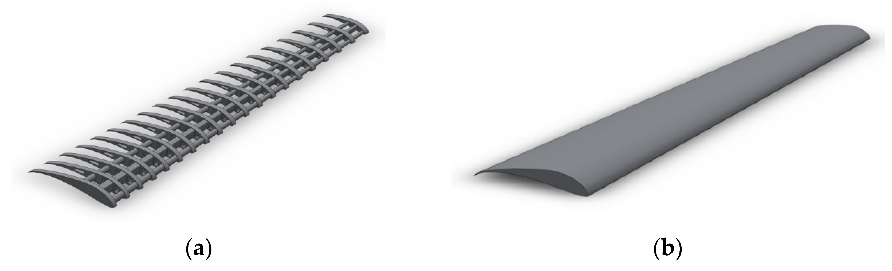
The laminate layup for the wing structure comprises a symmetric, balanced, and quasi-isotropic configuration as a high-strength carbon fiber/epoxy composite. The wing design is tailored to optimize mechanical performance under various loading conditions in addition to the inertia body force related to the reciprocating motion of the RA wing. The layers, comprising 50% of the laminate, are aligned with the wing span to maximize tensile and compressive strength, which carries the primary axial loads induced by bending moments. The layers constitute 30% of the laminate, and they are oriented to resist shear stresses from torsional rigidity. The layers comprising the remaining 20% provide transverse strength and buckling resistance, stabilizing the structure under compressive and out-of-plane loads. The symmetric and quasi-isotropic layup offers uniform stiffness and strength in all in-plane directions, improving the reliability of the wing. The diverse fiber orientations enable resistance to various failure modes, including fiber breakage and matrix cracking, contributing to the overall damage dominance of the wing structure. The composite is manufactured using pre-preg carbon fiber/epoxy with autoclave curing, ensuring high-quality laminates with an optimized fiber volume fraction of approximately 60%. The laminate configuration is designed to deliver optimal performance by maximizing the load-carrying capacity, shear resistance, and buckling stability. This makes it well suited for the high-performance RA wing structure, where weight efficiency, strength, and damage resistance are critical.
The maximum principal strain, total deformation, and radial (y-axis) deformation for the RA wing were determined to be 0.0066652, 19.742 mm, and 18.038 mm, respectively. The maximum stress component () reached 528.29 MPa under the given loading conditions, with transverse stress measured at 30 MPa and shear stress at 15 MPa. These stress metrics provide critical insights into the loading conditions experienced by the wing structure during operation. The material’s mechanical properties were evaluated to determine its capacity to handle these stress conditions. The material’s longitudinal tensile strength ( and compressive strength were found to be 3447.71 MPa and 2413.2 MPa, respectively. Similarly, the transverse tensile strength and compressive strength () were calculated to be 60 MPa and 150 MPa, respectively, with an in-plane shear strength () of 60 MPa. These properties reflect the material’s resilience to various stress components and ability to maintain structural integrity. The calculated safety margin (SM) was 2.2627, indicating that the wing structure operates within safe limits under the given conditions. The safety margin is a quantitative measure of the design’s reliability, highlighting its ability to withstand applied loads without failure. By evaluating these values, engineers can identify regions of potential failure, refine the design for enhanced performance, and ensure that the structure meets safety and operational requirements. This structural analysis provides a deeper understanding of the wing’s performance characteristics, including its deformation behavior, stress distribution, and structural capacity. The findings also underscore the importance of safety margins in predicting failure locations and guiding design optimizations to achieve a more robust and reliable structural design. These insights are invaluable for advancing the wing’s performance and validating its suitability for practical applications.
Various failure criteria are typically used to analyze a composite material for aerospace structures depending on their loading conditions, type of composite, and any specific failure mode you aim to capture.
Table 3 below summarizes examples of some common composite failure criteria, their equations, explanations of variables, and failure conditions. The maximum stress and strain criteria provide a quick evaluation for initial screenings to ascertain whether the stress or strain levels exceed the allowable limits. However, they do not account for stress component interactions and distinguish between various failure modes (interlaminar shear failure, fiber, and matrix). The Tsai–Wu failure criterion [
65] accounts for in-plane stress component interactions, which makes it versatile for handling multi-axial loading conditions typically encountered in wing structures. It may not be as complex as other failure criteria. Still, it is comprehensive enough to handle the nonlinear interactive nature of composite material behavior, especially for practical preliminary design and analysis. The Hoffman failure criterion [
66] considers the longitudinal, transverse, and shear stress interactions but may be less accurate in predicting specific failure in fiber-reinforced composites. The Hashin failure criterion is one of the best aerospace composite structure criteria, providing a detailed analysis of failure modes. The Hashin failure criterion [
67] can distinguish between tensile and compressive failure (fiber and matrix); however, it assumes unidirectional fiber reinforcements and requires detailed knowledge of the fiber and matrix properties. The Puck failure criteria [
68,
69] can predict inter-fiber (matrix-dominated) failure and requires a deep understanding of the material fiber and matrix properties. The Azzi–Tsai criterion [
70] is similar to the Hoffman criteria and accounts for stress component interactions using a quadratic relationship. It, however, may not be as accurate for complex multi-directional laminates and does not separate different types of failures. The Hashin criterion characteristics for differentiating between failure mechanisms (e.g., fiber breakage and matric cracking or delamination) and proving a more accurate assessment of material response under complex loading typical in wing structures makes it suitable for aerospace composites. The Tsai–Wu failure criterion is also beneficial for evaluating complex multi-axial loading problems while seeking a comprehensive and manageable prediction method. Checks were carried out using all the above criteria for the initial FEA investigations, and no failure was predicted. The Tsai–Wu (
) and Hashin criteria (
) using the data presented above and the equations described in
Table 3 yielded a failure coefficient less than 1 (
).
Numerous design iterations were undertaken to improve the stress distribution within the RA wing structure. These efforts included modifications to critical design parameters, such as increasing the thickness of the ribs and spars, incorporating additional ribs and spars, and systematically varying other structural features and configurations. Despite these extensive adjustments, the resulting simulated stress levels exhibited minimal improvement, indicating that the high stresses induced by the significant inertial forces inherent to the reciprocating motion remained unresolved. This persistent issue underscored the inadequacy of conventional design alterations in effectively mitigating stress concentrations. Consequently, it became evident that a more sophisticated and systematic approach, such as topology optimization, was necessary to achieve a significantly improved stress state. By addressing the limitations of traditional design adjustments, topology optimization was pursued to strategically redistribute material within the wing structure, thereby enhancing its load-bearing capacity and reducing stress to acceptable levels.
4. Topology Optimization of an Aircraft Wing
Topology optimization is employed to further improve the RA wing’s structural rigidity and is one of three major structural optimization methods. This method numerically determines the best structural configuration of a design problem based on the minimization or maximization of an objective against one or more constraints [
71,
72]. One significant benefit of topology optimization is the ability to achieve functional design solutions from arbitrary initial design spaces. The other structural optimization methods, size and shape optimization, require the user to provide an initial structural design, which may require design experience or expertise.
Since its conceptualization in the 1980s, the topology optimization field has been limited for several decades due to the often intricate nature of the design solutions. Design solutions are often difficult to manufacture using traditional production methods. Despite this, very complex topologies are now attainable due to additive manufacturing technologies’ process improvement and unique characteristics. This development has ensured widespread acceptance and research interest in topology optimization methods.
During the design process, topology optimization is frequently used to examine and evaluate several design possibilities in accordance with the stated goals, such as weight minimization, stress reduction, stiffness improvement, and more. Researchers believe that the three topology optimization techniques used on the A380 led to weight reductions of about 1000 kg per aircraft [
73]. The geometric volume in which the material can be distributed is usually specified as the design domain. There have been various research examples of wing topology optimization. Some examples are briefly discussed below.
Wing topology optimization was applied to the airfoil profile wing NACA 23015 [
74]. The design space for load support was the internal structure, with wing supports acting as the constraints. The load routes were analyzed, and until the topology optimization objective function was satisfied, gradual material removal was carried out while upholding the optimization limitations or constraints. Minimizing compliance or increasing the stiffness of the entire structure was the objective function. The optimization constraint was to keep the volume percentage of the whole design space under 30%. The point where the material will be displayed was chosen to have a density fraction of 50%. The standard 2024 aluminum alloy material was used. The density fraction of the final post-process product of the optimized RV-4 wing segment was set to 38%.
Topology optimization was also applied to a wing box structure, and the goal was to create a method that enables the global compliance topology optimization method to be used in designing components that experience both diffused flight loads and locally applied loads [
73]. The topology optimization of the wing box ribs was approached from many angles. By employing the lowest global compliance topology optimization formulation to optimize a wing box rib that is fully integrated into a wing box structure, a global analysis method for topology optimization of wing box ribs was obtained. Due to the formulation’s apparent preference for locally applied loads over globally applied and diffused rib loads, it was determined that the global analysis/optimization strategy was ineffective for wing box rib topology optimization. The local approach to topology optimization of the wing box ribs consisted of establishing the interface loads for the critical flight cases, selecting the critical loads, and performing topology optimization of the model. The local analysis method involved completing a free-body load analysis with a baseline rib design incorporated into a global wing box load diffusion model. While using various load cases and a min–max formulation, the topology optimization’s objective was to handle as many load situations as possible while minimizing global compliance for the rib only. The rib topology optimization design model had to accommodate both the global flight loads and the locally applied loads because all loads were now imposed locally. A drawback of this strategy was that local rib loads would not change automatically when using a local analysis approach. Even with the min–max formulation, which automatically balances each load case to produce an overall “stiffness”, the researchers were still unsure of how to produce the proper stiffness because various load cases or even different load case contributions might call for different rib stiffness. Finally, a different local analysis/optimization strategy was considered. The total elastic energy in each load case was constrained to be less than that of the baseline design using the minimal weight formulation. By doing so, the researchers demanded a lighter design with the same or more stiffness than the baseline design, which made it more effective from a stiffness perspective. The limitation of the current approach was the lack of requirement for a robust baseline design to set precise energy design targets. Since it gives the topology optimization specific and achievable stiffness design targets in terms of an energy measure, this limitation of the alternative local approach is also considered its main benefit.
The engineering practice of choosing the best shapes and material distributions for predetermined structural goals is known as computational morphogenesis. Topology optimization was applied to optimize a full-scale wing structure. After 400 steps of the morphogenesis process, sophisticated topology optimization was used for a full-scale wing design utilizing the Curie supercomputer-based morphogenesis program that supports the giga-voxel resolution and has the potential to provide insights into the optimal structure. The reasonable estimate of the weight reduction that can be achieved was 2–5% or 200–500 kg for each wing using the unique rib pattern and the curved spars. The researchers indicated that a weight loss of between 400 and 1000 kg translates into an estimated reduction in fuel consumption of between 40 and 200 tons annually [
75]. Furthermore, the approach described in their study implied that it is readily transferable to related morphogenesis issues in other technical fields. For additional examples of how topology optimization can be used for airplane component parts, readers are referred to the references of [
76,
77,
78,
79].
4.1. Topology Optimization of the RA Wing
This section discusses the use of topology optimization in the development of the RA wing while emphasizing key theoretical formulations. An important aspect of topology optimization is formulating the problem to account for the functional conditions of the structure.
Most topology optimization approaches are based on the finite element method. A popular formulation to enhance structural rigidity is compliance or strain energy minimization [
71,
80,
81], which can be thus written as follows:
In (5), is a pseudo-density design variable that indicates how much material should be present in a finite element. is the compliance cost function of the optimization, while and are the external loads and global displacement vectors, respectively. In the finite element equation, is the global stiffness matrix, while in the volume fraction constraint, is the volume of a single finite element, is the total volume of the structural domain, and is the volume fraction. Finally, are the Young’s Moduli of a material element, a solid, and a void region, respectively.
In the finite element formulation of the RA wing, the load vector is populated by external loads from the lift, drag, and inertia effects and gravity:
where
are the force contributions from the reciprocating acceleration of the wing and gravity. In order to alleviate computational difficulties that arise from complicated load scenarios, the load condition is simplified by considering only the lift and drag forces during the optimization. Therefore, the load vector is expressed as follows:
The effects of inertia were employed in the final FEA simulation. A schematic of the workflow of topology optimization of the wing is shown in
Figure 5.
In
Figure 5, the optimization process begins with establishing the design domain, design variable, and material properties. Since the current topology optimization method used (pseudo-density design gradient-based) is based on FEA, a mesh is generated, as shown in the next stage. The design problem must first be defined by imposing the necessary loads and boundary conditions to compute the displacement, sensitivity, and objective functions. A static FEA is then computed to obtain the displacement field, the values of the compliance objective, and the derivatives of the objective and constraint functions (also known as sensitivity functions). The objective and sensitivity information and an initially predicted design variable field are sent to an optimizer to update the design variables. Typically, the optimizer is a mathematical program or heuristic algorithm. These design variables form the topological solution for the present iteration. Convergence is determined by comparing the maximum deviation of the design variables and/or objective function between the present and previous iterations and threshold values. If the maximum deviations are above the specified thresholds, the optimization, with the updated design variables, is returned to the stage where displacements are computed. The process is performed iteratively until convergence is reached. Often, the converged topology comprises several jagged features, especially for low-resolution optimizations. This is corrected by smoothing operations as post-process steps to obtain the final optimized topology.
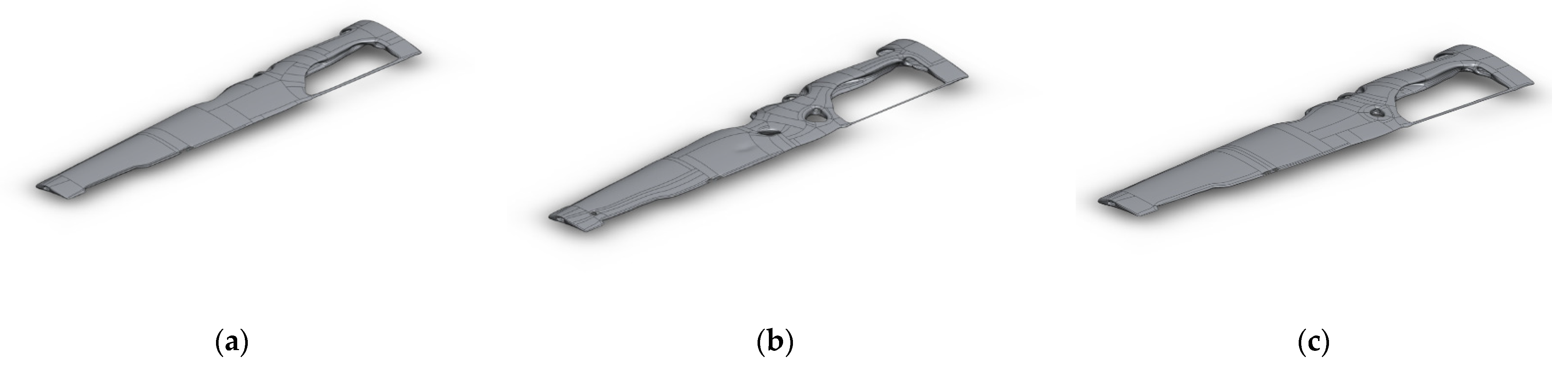
The optimization process was implemented in nTopology [
82] for three design iterations corresponding to three mass fractions—0.63, 0.65, and 0.67—as shown in
Figure 6:
4.2. Topology Optimization Results and Discussion
The three optimized design iterations were analyzed to compare their structural performance and weight characteristics under similar loading conditions, as described in
Section 3. The first design iteration weighed 18.704 kg, the second 18.116 kg, and the third 19.393 kg. These mass variations reflect the adjustments made to balance weight reduction and structural integrity during the optimization process.
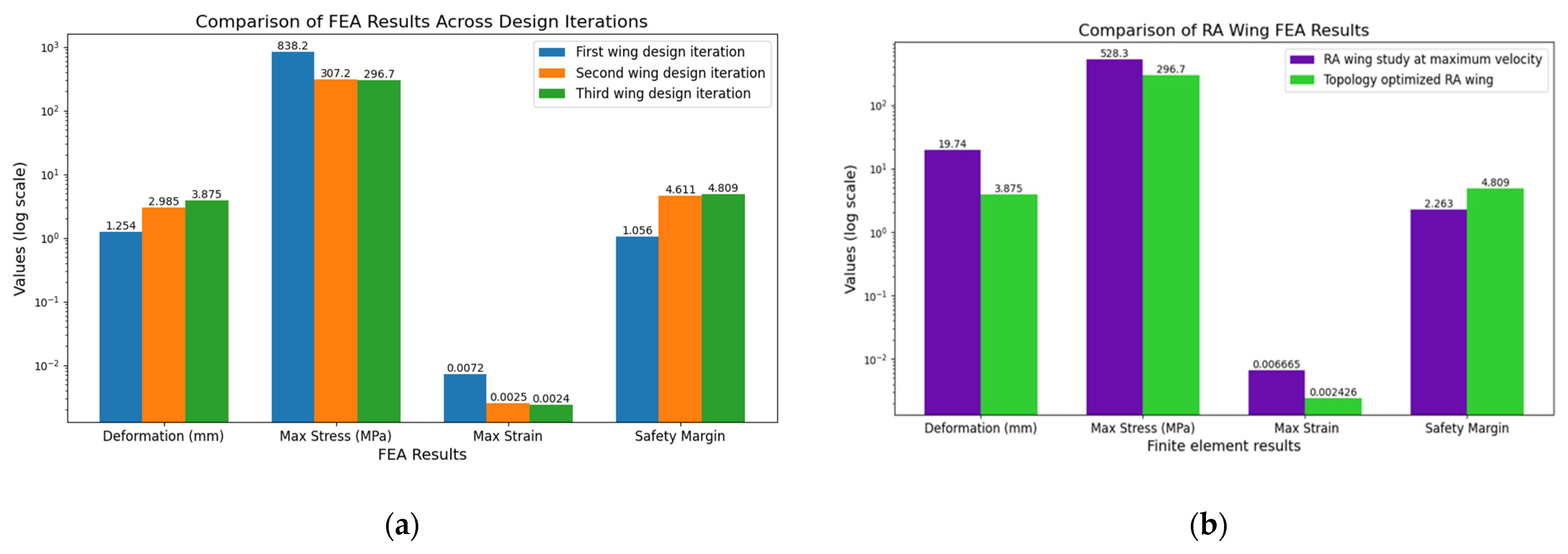
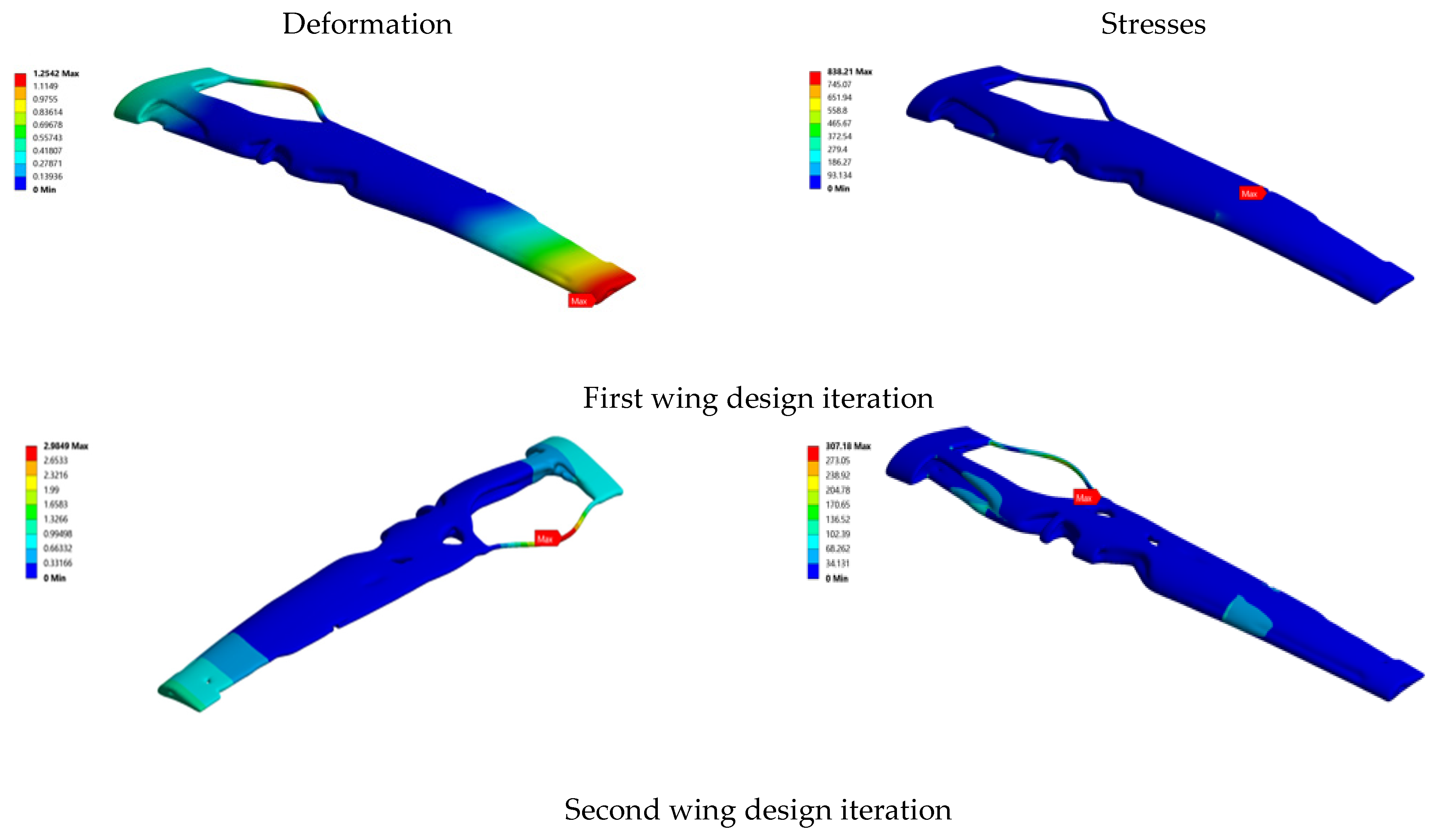
For the first design iteration, the maximum principal strain was 0.007202, the total deformation was 1.2542 mm, and the maximum stress (σ1) reached 838.21 MPa. This iteration’s safety margin (SM) was calculated to be 1.0564, indicating marginal adherence to safety requirements. Significant improvements were observed in the second design iteration, with a maximum principal strain of 0.0024893, total deformation of 2.9849 mm, and maximum stress of 307.18 MPa. The safety margin for this iteration improved significantly to 4.6114, demonstrating enhanced structural reliability. The third iteration further refined the design, achieving a maximum principal strain of 0.0024262, a total deformation of 3.8747 mm, and a maximum stress of 296.72 MPa. This iteration also exhibited the highest safety margin of 4.8092.
Comparing the three iterations reveals that the first design exhibited the least deformation (1.2542 mm), followed by the second (2.9849 mm) and third (3.8747 mm) iterations. However, the observed increase in deformation across iterations can be attributed to efforts to reduce material usage for weight optimization. Despite this, the second and third iterations achieved a significant reduction in maximum stress compared to the first design (838.21 MPa), with the second and third designs reducing stress to 307.18 MPa and 296.72 MPa, respectively. These results highlight improved stress distribution and load-bearing capability in the optimized designs.
The steady decrease in strain across the iterations indicates increased stiffness and effective material utilization. Additionally, the safety margins improved from 1.06 in the first iteration to 4.61 and 4.81 in the second and third iterations, surpassing safety requirements and ensuring robust structural performance. The second and third iterations struck a balance between structural integrity and weight reduction while maintaining adequate safety margins. Ultimately, the third design iteration was selected as the final optimized design due to its superior performance under the given loading conditions.
Further validation of the optimized design was conducted using the Tsai–Wu (F = 0.4045 < 1) and Hashin criteria (0.31 < 1). These failure coefficients, derived from equations in
Table 3, confirmed that the design remained within failure limits (F ≤ 1).
Table 4 summarizes the results of failure criteria checks for the initial FEA analysis and the topology-optimized design, demonstrating no failure in all cases. This robust structural performance verifies the effectiveness of the optimization process.
The visualized data provided in this study enable engineers to compare stress values, strain distribution, and deformation more effectively. This comparison facilitates informed decision-making regarding material selection, design modifications, and the establishment of appropriate safety margins. These findings emphasize the importance of iterative design and optimization in achieving lightweight yet structurally sound engineering solutions.
Compared to the initial FEA results for the RA wing at maximum velocity, the topology-optimized wing demonstrated substantial improvements across all evaluated performance metrics.
Figure 7 presents a detailed comparison of the two designs, highlighting the significant benefits of optimization. The topology-optimized wing exhibited a dramatic reduction in deformation, measuring just 3.87 mm compared to the 19.74 mm deformation observed in the RA wing. This represents an 80.4% decrease, indicating greatly enhanced rigidity and the ability to withstand aerodynamic loads with minimal displacement. The improvement in deformation underscores the optimized wing’s superior structural stiffness, which is essential for maintaining aerodynamic performance and structural integrity during high-speed flight. The maximum stress experienced by the topology-optimized wing was significantly lower, measuring 296.72 MPa compared to 528.29 MPa in the RA wing. This 43.8% reduction highlights the optimized wing’s improved load-bearing capacity and ability to distribute stresses more efficiently across the structure. The reduction in localized stress concentrations suggests that the optimization process effectively redistributes material to reinforce critical load paths, minimizing the risk of structural failure under extreme conditions. Strain levels were also substantially reduced in the optimized wing. The maximum strain observed was 0.0024262, a 63.5% reduction compared to the 0.0066652 strain observed in the RA wing. This improvement reflects the optimized design’s enhanced stiffness and resistance to elastic deformation. By reducing strain, the optimized wing ensures better resistance to shape distortion under operational loads, contributing to its reliability and long-term performance. The safety factor of the topology-optimized wing was significantly improved, increasing from 3.2627 in the RA wing to 5.8092 in the optimized design. This 78% increase in the safety margin demonstrates the optimized wing’s ability to maintain structural integrity under loading conditions that far exceed normal operating limits. The higher safety factor reflects compliance with stringent design requirements and a substantial buffer against potential failure, ensuring higher operational reliability. The high-stress regions in
Figure 8 are critical for evaluating fatigue life, especially in composite materials where delamination zones may develop under cyclic loading. These areas require further investigation using analytical fracture mechanics to analyze crack initiation and growth behaviors. The design’s capacity to prevent crack propagation can be validated by integrating advanced fatigue analysis and damage tolerance models, thereby ensuring structural stability and reliability for reciprocating aircraft (RA) applications.
The overall performance comparison establishes the superiority of the topology-optimized wing over the RA wing at maximum velocity. The optimized design significantly reduced deformation, stress, and strain while improving the safety factor. These findings validate the effectiveness of topology optimization in achieving lightweight yet robust structural components for aerospace applications. The optimization successfully balanced weight reduction with enhanced structural integrity by strategically redistributing material and eliminating unnecessary mass. The demonstrated improvements in the topology-optimized wing design highlight its feasibility and effectiveness as the primary lift component for RA aircraft. Its increased stiffness, reduced stress, and improved safety margin ensure enhanced reliability and performance under demanding operational conditions. These results underscore the potential of iterative design and topology optimization techniques to drive advancements in structural performance, offering valuable insights for developing lightweight, high-performance aerospace systems. Future studies could explore dynamic loading conditions, fatigue resistance, and further optimization to refine other critical aircraft components, extending the benefits demonstrated in this study.
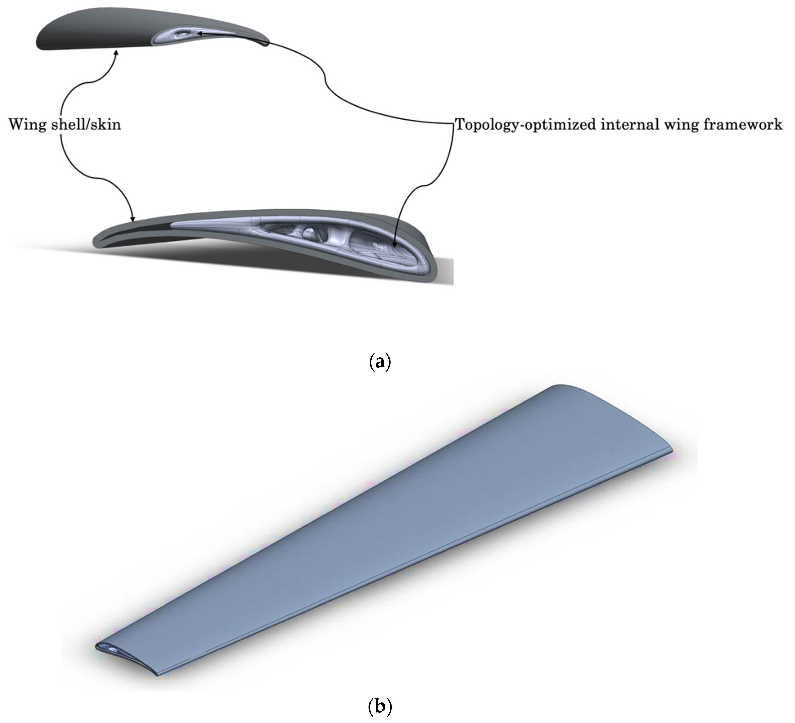
Figure 9 depicts the fully optimized framework, which comprises the wing and shell, and highlights the effectiveness of the current topology optimization iteration in achieving a balance between structural integrity and weight reduction. Nevertheless, further refinement of the optimization process is feasible and could uncover an even more efficient structural configuration. By employing multi-objective optimization algorithms or enhancing mesh density during analysis, improved structural performance may be attained. Despite this potential for enhancement, the current iteration provides a solid baseline for future developments and represents a significant milestone in this phase of the study. Topology optimization of structures has experienced notable advancements in design; however, challenges persist in machining and manufacturing processes. The RA topology-optimized wing aims to minimize stress and attain optimal weight through innovative shapes. The topology design serves as a blueprint for further developing new geometries for the RA, which will undergo additional rigorous validation and analyses, such as fatigue analysis and fracture mechanics studies, to ensure its performance and reliability.
5. Advancing Reciprocating Wing: Study Significance, Validation, and Technology Readiness for Air Mobility
The RA research explores the reciprocating motion of fixed wings and its potential for addressing technical challenges while eliminating reliance on rotary wings for generating vertical lift. This study introduced the RA wing as a foundational concept for an efficient lift-generating mechanism, offering a promising alternative to hybrid and other VTOL UAV configurations.
The distinctive design of the RA VTOL aircraft allows for a seamless and natural transition between VTOL and fixed-wing operation, whether in cruising or forward-flight mode. This capability addresses critical limitations of existing VTOL technologies. While the reciprocating motion of the RA wings introduces concerns related to potential vibrations and inertial forces, the advantages of this design outweigh these challenges. Key benefits of the RA concept include improved flight speed, range, and energy efficiency; reduced aircraft production and operating costs; enhanced stability in turbulent conditions due to the wing’s ability to adjust its angle of attack (AoA); and increased reliability and safety.
Given the high-stress levels observed in earlier studies, optimizing the wing’s internal structure is critical to withstand operational loads effectively. Through topology optimization, this study achieved a structurally enhanced wing design capable of meeting the demanding performance requirements of RA operations. The wing design represents a significant advancement in structural stability, enabling the RA module to perform reliably and efficiently in both VTOL and fixed-wing modes.
The design and functionality of a VTOL vehicle is a multidisciplinary problem that involves several factors such as aerodynamics, structural analysis, stability, etc. Several VTOL vehicle development advancements must scale through several technological readiness levels (TRLs) and manufacturing readiness levels (MRLs) to achieve full commercial deployment. The future of RA-driven VTOL is promising and depends on demonstrating several factors to advance in the TRL ladder, which include the following:
A small UAV prototype will be developed to further validate the feasibility of the reciprocating wing. This experiment will directly measure aerodynamic forces, structural responses, and dynamic loading conditions. Wind tunnel testing will also validate the CFD simulation for lift and drag, structural loads, and vibration analysis. Below are the RA aircraft TRL milestones.
TRL 3→4: Validate the RA component to assess computed aerodynamic and structural integrity.
TRL 5→6: Conduct small-scale experimental validation by constructing a UAV prototype and/or performing wind tunnel testing.
TRL 7→8: Test the full-scale prototype in real-flight conditions to evaluate its performance under operational loads.
Improvements in advanced composite materials, control systems, and aerodynamics design are crucial in the technological advancement of RA technology. Regarding efficiency and performance, the RA-driven VTOL could demonstrate superior efficiency and performance in specific applications compared to existing VTOL technologies. The RA VTOL is potentially more efficient in particular flight regimes than traditional rotary-wing aircraft due to its unique aerodynamic properties of the reciprocating wing or airfoils. Regarding market demand, several considerations could increase the demand for specialized VTOL applications. Examples include urban air mobility (UAM) or advanced air mobility (AAM), military operations, and search and rescue missions, which could be factors that drive the demand for VTOL development. In addition, all safety standards and regulations must be met for specialized adoption.
The AAM or UAM industries have contemplated whether the first Federal Aviation Authority (FAA) certification of an eVTOL will come to fruition. The entry-into-service (EIS), in which an OEM must pass four major certifications, is also essential. EIS refers to the time at which OEMs deliver to their customers, and book and earn revenue from passengers. The eVTOL market is dynamic and constantly evolving, with new players and firms competing for market share and certification. Key factors in development and deployment are regulatory bodies’ approvals, funding from major investors, technological development, building infrastructure, and establishing a solid customer base.
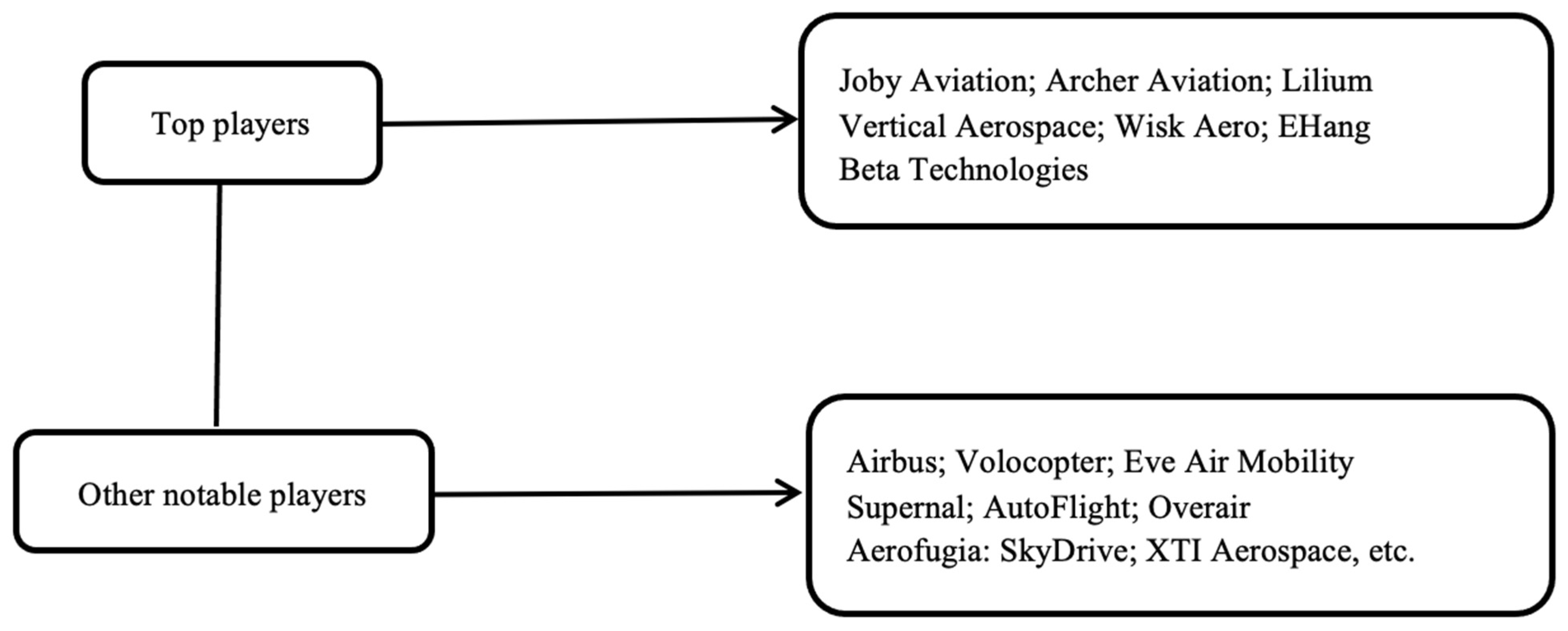
Figure 10 shows examples of the top players (the current leaders: Joby and Archer Aviation, Lilium, Vertical Aerospace, Wisk Aero, EHang, and Beta Technologies) in the urban eVTOL air mobility industry. For an embryonic sector such as eVTOL vehicles, where some of the top companies have been testing for years and looking to certify a new aircraft with the FAA, it may still be some years away due to the regulations and politics. Many of these eVTOL players (new and existing) may turn to commercial service vehicles, which have better certification standard control, and they will have to come up with various novel designs that meet the regulations for quicker certifications than being the first to certify a new VTOL aircraft from their latest prototype designs. They all must fly conforming aircraft prototypes to have hopes of being certified to launch their eVTOL or air taxis, while others may be forced to use their prototype for support only and delivery services. RA-driven VTOL represents an innovative approach to vertical flight with potential advantages in terms of efficiency and performance. Its future will depend on continuous research and validation development, overcoming technical challenges, and proving its value in practical applications.
6. Concluding Remarks
This study comprehensively examined unconventional UAV designs, focusing on the RA wing’s performance under maximum velocity conditions and its structural optimization to improve its stress states. The analysis highlighted the challenges and benefits of this novel design, emphasizing its potential to redefine VTOL capabilities.
Key Findings:
- 1.
Structural Optimization and Stress Performance:
The RA wing’s internal structure underwent iterative refinement through finite element analysis (FEA) and topology optimization over three design iterations. The resulting optimized design exhibited the following:
Deformation Reduction: Total deformation decreased by 80.4% (from 19.74 mm to 3.87 mm).
Stress Improvement: Maximum stress dropped by 43.8% (from 528.29 MPa to 296.72 MPa).
Safety Factor: The safety margin increased by 78%, reaching 5.8092, ensuring the design meets stringent structural requirements.
These improvements reflect a robust structural configuration capable of handling the inertial forces induced by reciprocating motion while maintaining aerodynamic performance.
- 2.
Failure Analysis Validation:
Failure criteria checks using the Tsai–Wu, Hashin, and Hoffman methods confirmed that the optimized RA wing design remained within safe limits under operational loads. The results showed significant reductions in localized stresses and material strain while enhancing load-bearing capacity.
- 3.
Aerodynamic and Operational Advantages:
The RA wing’s ability to perform seamlessly across VTOL and forward-flight modes offers enhanced energy efficiency, extended range, and stability. These properties make RA-driven VTOL a competitive alternative for urban air mobility (UAM), advanced air mobility (AAM), and specialized missions like search and rescue operations.
Path Forward
The RA-driven VTOL design has the potential to revolutionize unconventional UAVs, overcoming existing challenges like noise, mechanical complexity, and transition inefficiencies between flight modes. The successful topology optimization highlights the role of advanced design tools in achieving lightweight yet structurally sound wings. Future research will focus on the following:
Fatigue Analysis: Evaluating lifecycle durability under dynamic loading.
Fracture Mechanics: Assessing total life (crack initiation and propagation).
Dynamic Load Optimization: Further refining performance under real-world flight conditions.
Addressing these areas will allow the RA wing to advance along the technology readiness level (scale) described in
Section 5 and advance the RA technology toward commercialization. This study will pave the way for robust, reliable, and energy-efficient VTOL aircraft that meet the growing demands of next-generation vertical lift aerospace systems.


