1. Introduction
When a ship sails at sea, it is inevitably affected by environmental factors such as wind and waves, which induce complex motions in its attitude. These disturbances not only reduce the precision and efficiency of shipboard operations but also compromise the stability and reliability of onboard systems such as radars and electro-optical sensors. Consequently, the development of shipborne stabilization platforms capable of isolating the effects of hull motion has become an important research focus. Among various solutions, parallel mechanisms are widely adopted in such platforms due to their high stiffness, strong load-bearing capacity, and superior dynamic performance.
Ref. [
1] proposed a novel six-degree-of-freedom (6-DOF) spatial parallel platform, in which three identical kinematic chains connect a five-bar linkage to the base. The study demonstrated that, by using only lightweight elastic components, such a structure can achieve effective static balancing. Ref. [
2] introduced a redundantly actuated 6-DOF parallel mechanism with a partially decoupled rotational structure, enabling efficient real-time control and allowing full 360° rotational motion in six degrees of freedom. Ref. [
3] developed a 3-PUU parallel mechanism with 2R1T degrees of freedom. With appropriate parameter settings, the 3-PUU mechanism can be applied to machining and pick-and-place operations. Ref. [
4] presented a 5-PSS/UPU parallel mechanism, where five degrees of freedom can be adjusted in real time through a single actuated branch, thus maintaining dynamic balance. Ref. [
5] designed a novel U-PRU-PUS parallel mechanism, whose tracking performance was improved through optimization of structural parameters. Ref. [
6] proposed an improved six-degree-of-freedom hybrid serial–parallel platform for ship wave compensation. Comparative analysis with the Stewart platform showed that the proposed mechanism offers advantages in wave compensation performance.
Shipborne parallel stabilization platforms are highly nonlinear, strongly coupled, and multivariable dynamic systems. In unpredictable and stochastic ocean environments, they are subject to various loads and disturbances induced by ship oscillations. The system exhibits significant dynamic and disturbance uncertainties, which pose major challenges for control design. Ref. [
7] proposed a sliding mode variable structure control (SMVSC) scheme based on the mathematical model of the control loop and the operational characteristics of shipborne weapon stabilization platforms (SPOSWs). Simulation results demonstrated that SMVSC not only satisfies static and dynamic performance requirements, but also significantly enhances system robustness and disturbance rejection. Ref. [
8] developed a ship stabilization platform control strategy based on motion-prediction model predictive control (MPMPC). Both simulations and experiments confirmed that MPMPC achieves higher tracking accuracy than conventional MPC. Ref. [
9] proposed a sliding mode control scheme for a shipborne Stewart platform, together with a novel velocity feedforward compensator to enhance control performance. A Lyapunov-based analysis rigorously proved the boundedness of the control error, and simulations further validated the effectiveness of the proposed approach. Ref. [
10] introduced a wave-compensation triple-loop control strategy for shipborne Stewart platforms based on active disturbance rejection control (ADRC). The results showed that the method provides superior performance in power reduction, decoupling, and disturbance rejection. In the same year, ref. [
11] also proposed a modal-space control strategy to address the low natural frequency and vibration susceptibility of parallel stabilization platforms. A modal-space sliding mode controller was designed, and simulations demonstrated its advantages in compensation accuracy and robustness against disturbances. Ref. [
12] presented a robust backstepping sliding mode control (RBSMC) method. A Stewart platform simulation model was established, and results showed that the proposed approach effectively improved the compensation rate. Ref. [
13] proposed a robust stabilization control method based on a proportional–triple extended state observer (PTESO), which estimates total disturbances including dynamic uncertainties, unknown time-varying external disturbances, and couplings among state variables. Comparative studies validated the effectiveness of the proposed strategy. Ref. [
14] developed a BP neural network-based PID control algorithm, where the PID parameters are adaptively tuned by a backpropagation neural network. The simulation results indicated that, compared with conventional PID control, the proposed method achieves higher compensation accuracy along three directions under different sea conditions. Ref. [
15] addressed the impact of complex sea states on landing platform stability and proposed a novel control compensation method. A recursive least-squares AR prediction algorithm was designed, and the experimental results demonstrated improvements in compensation accuracy of 59.6%, 60.3%, 48.4%, and 47.9%, respectively. Ref. [
16] further proposed a composite control scheme based on inverse dynamics, incorporating an equivalent input disturbance (EID) method with robust feedback control to counteract unknown external disturbances. The experimental results showed that this approach outperforms several conventional methods in resisting both internal and external disturbances. Ref. [
17] presented a model predictive control strategy for shipborne stabilization platforms that explicitly considers load disturbances. Both simulations and experiments verified that this method exhibits stronger robustness and disturbance rejection compared with traditional MPC. Finally, ref. [
18] proposed a novel two-layer online adaptive predictive control strategy to address the time-varying parameters of electro-hydraulic servo systems under different operating conditions, strong coupling among platform actuators, and the randomness of ship motion. The results demonstrated that, compared with traditional single-layer MPC, the proposed two-layer approach significantly improves attitude compensation accuracy, dynamic response speed, system stability, and computational efficiency.
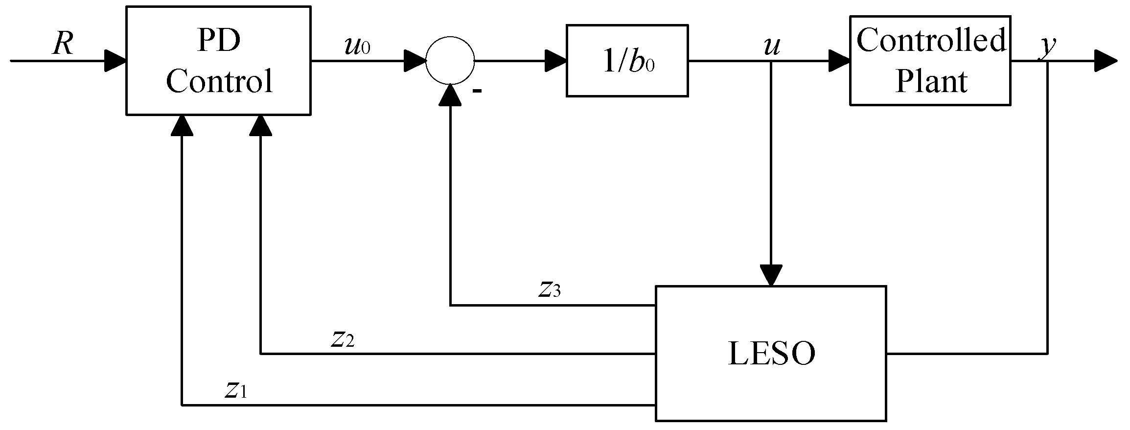
The core concept of active disturbance rejection control is to unify system uncertainties and external disturbances into a “total disturbance,” which is estimated and compensated in real time using an extended state observer. This approach reduces reliance on precise system modeling. To enhance engineering practicality, LADRC employs a linear extended state observer and a linear controller, thereby simplifying parameter tuning and significantly reducing implementation complexity while maintaining robustness. Ref. [
19] introduced an improved ADRC controller for a 6-DOF parallel platform. Under disturbance conditions, the controller achieved precise trajectory tracking, and both simulation and experimental results verified its effectiveness in driving the 6-DOF platform to accurately realize the desired motions. Ref. [
20] proposed a second-order LADRC applied to the velocity loop to enhance disturbance rejection, enabling the system to track targets stably and accurately. Simulation results demonstrated that adopting LADRC in the velocity loop significantly improves control performance and robustness against disturbances. Ref. [
21] modeled the multi-loop structure of a servo system and designed a linear ADRC to enhance control performance and disturbance rejection. The results showed that the proposed method achieves better control effects and stronger robustness compared with conventional approaches. Ref. [
22] developed an improved ADRC based on particle swarm optimization (PSO), which simplified the controller structure and reduced the number of parameters requiring manual tuning. By further optimizing the parameters through PSO, the improved ADRC exhibited reduced overshoot, faster response, higher accuracy, and stronger disturbance rejection compared with a traditional PID controller, thereby demonstrating superior reliability and robustness. Ref. [
23] addressed the insufficient disturbance suppression capability of conventional ADRC in stabilization platforms by proposing a VGD-ADRC method. Results indicated that VGD-ADRC effectively eliminates overshoot, improves noise suppression, and enhances tracking accuracy in stabilization platforms.
In this work, a novel shipborne parallel stabilization platform with a 3RRS–RUS configuration is designed, and a motor-based three-loop control strategy based on SMDO–LADRC is proposed. Finally, simulations and experiments are conducted to demonstrate its strong robustness and disturbance rejection capabilities. The main innovations and contributions of this study are summarized as follows and a comparison between the proposed mechanism and the conventional Stewart platform is summarized in
Table 1.
1. A novel 2R1T asymmetric three-degree-of-freedom redundant parallel mechanism, the 3RRS–RUS shipborne stabilization platform, is designed through type synthesis. Its feasibility is verified through degrees-of-freedom analysis, evaluation of parasitic motions, and kinematic analysis.
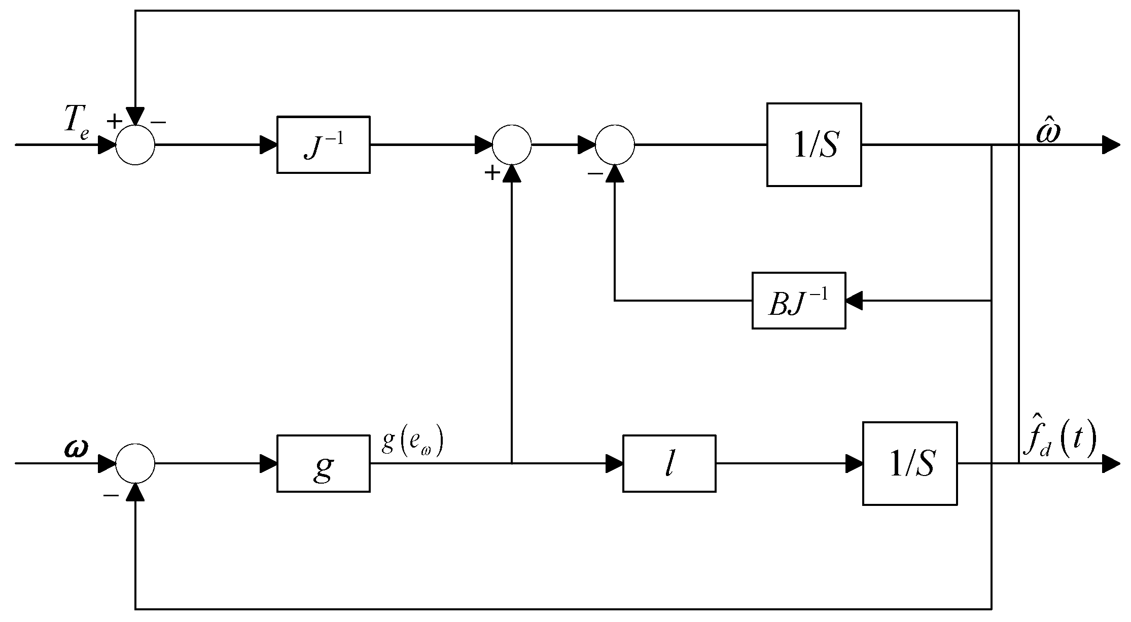
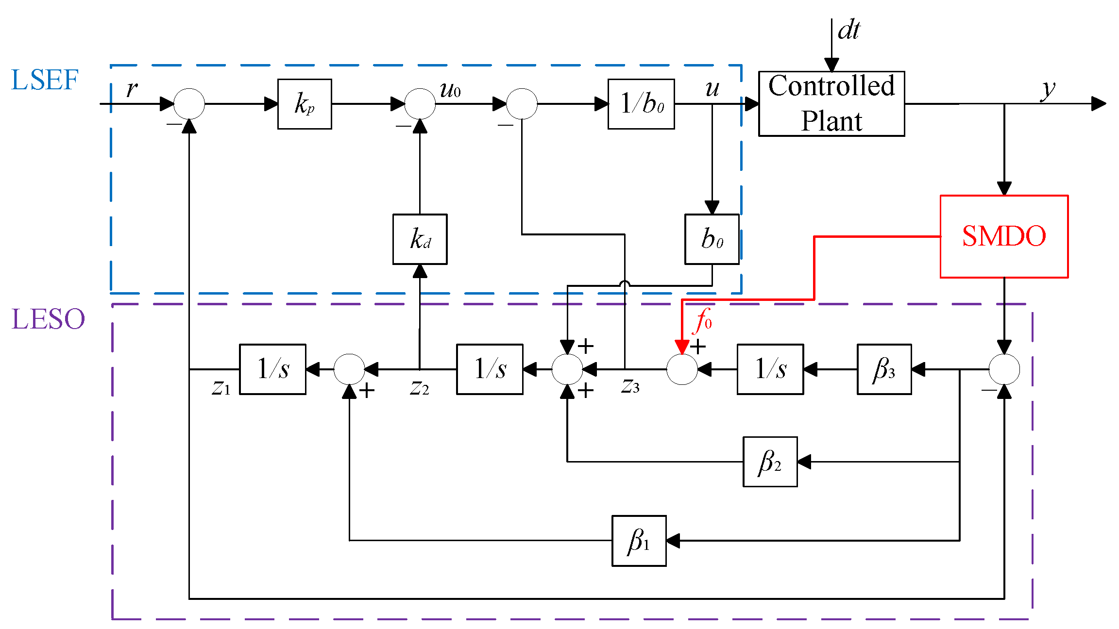
2. The traditional LADRC is derived and decoupled, and a new extended state observer and control law are designed. A sliding-mode disturbance observer is introduced to estimate the total system disturbance. The observed disturbance is incorporated into the LESO state equations as a compensation term, allowing the LESO to monitor only the residual disturbance. This approach not only reduces the observation burden on the LESO but also improves disturbance estimation accuracy and enhances closed-loop disturbance rejection performance.
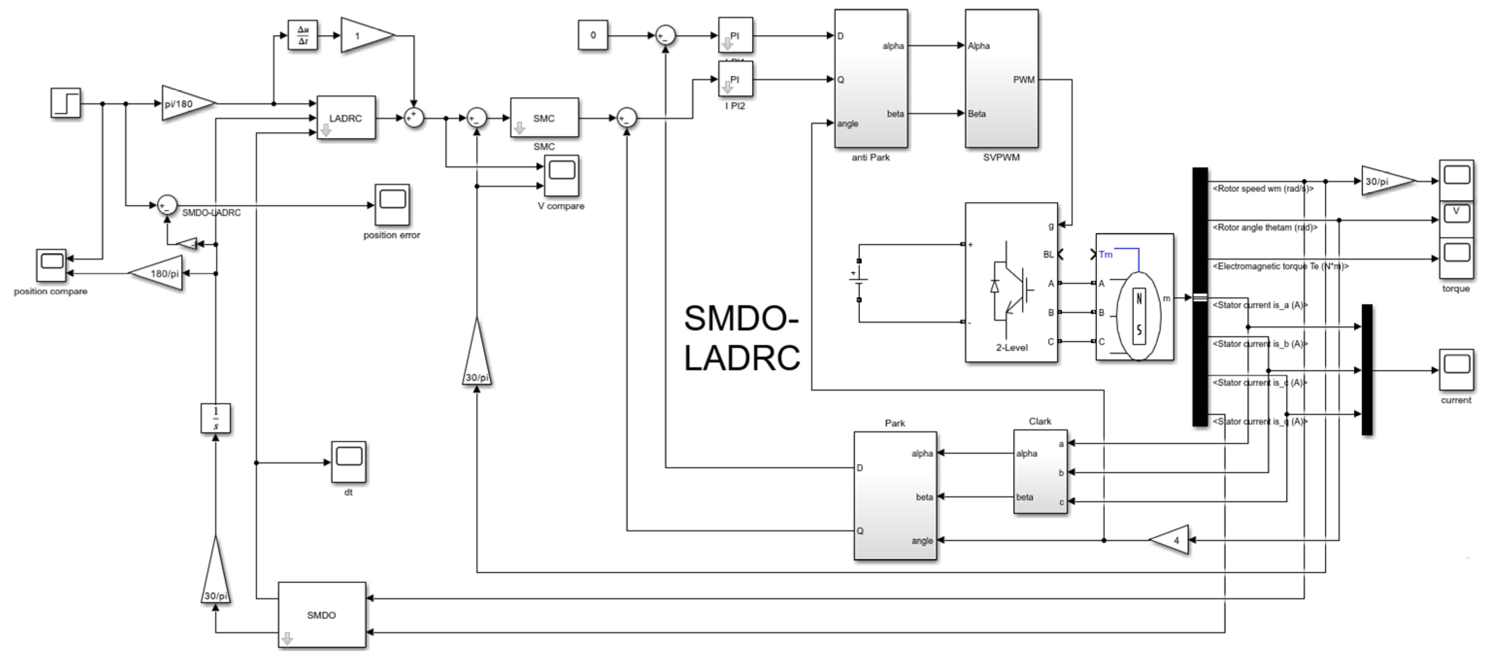
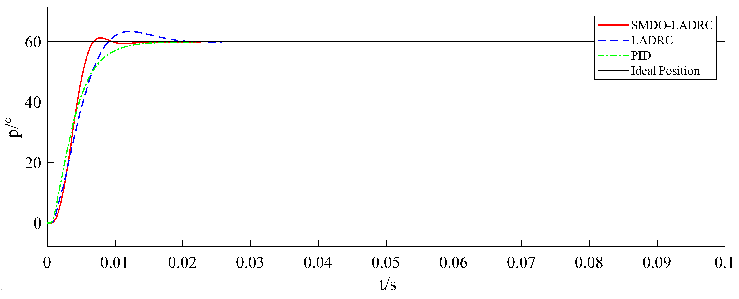
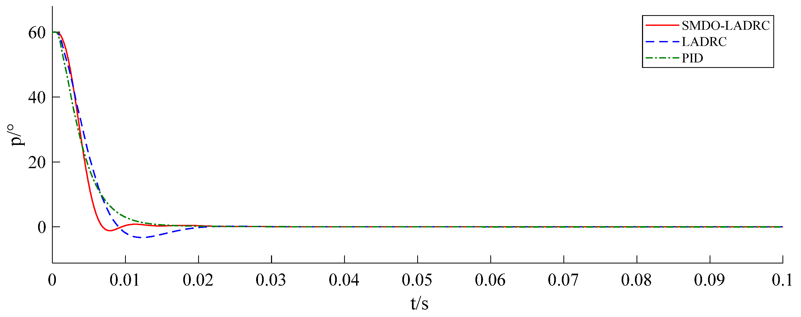
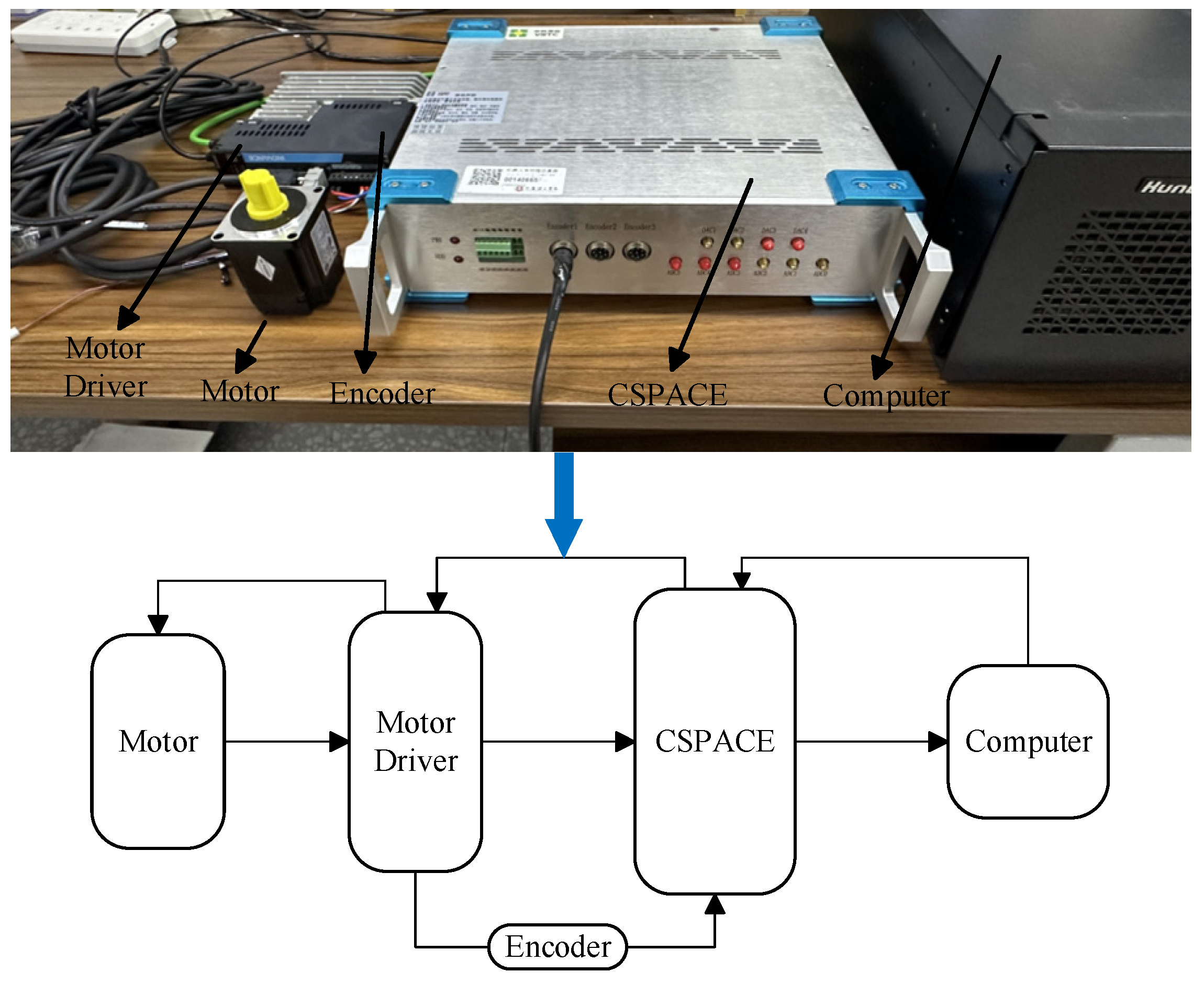
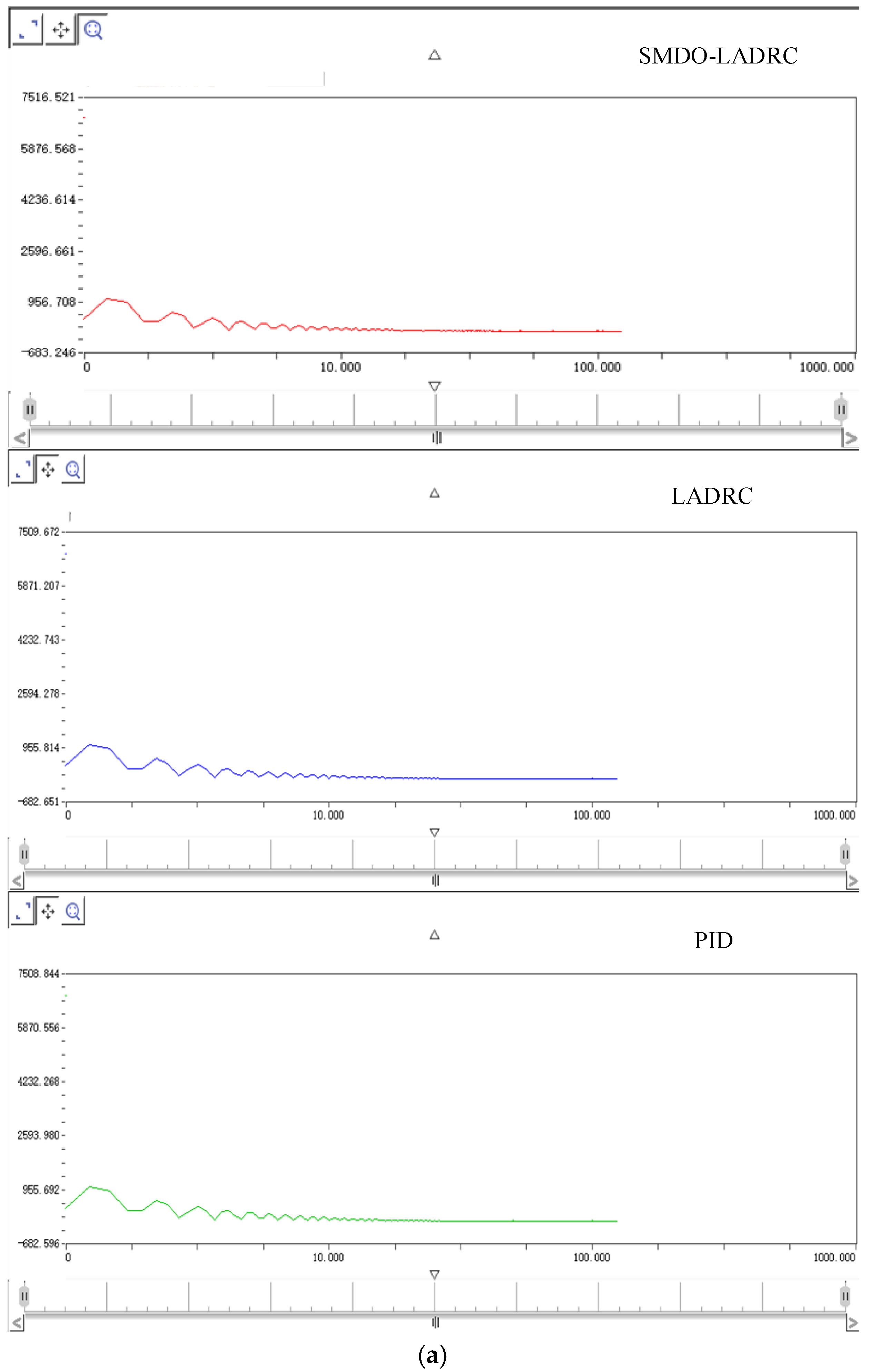
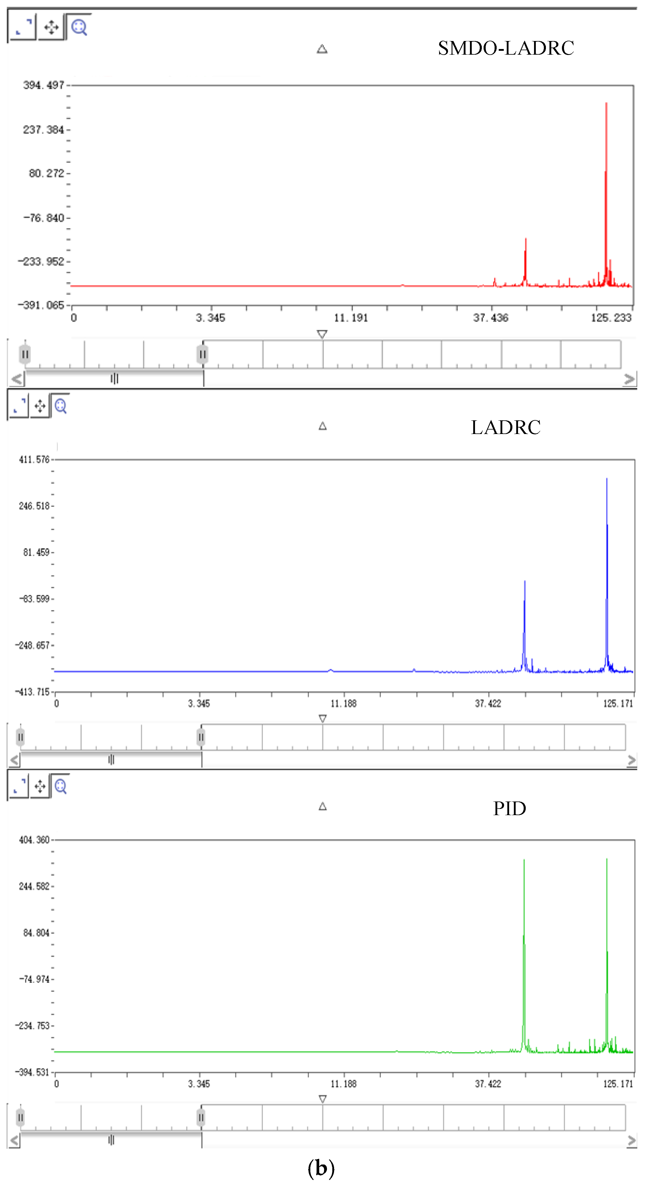
3. Three-loop control experiments on the servo motor are conducted using the Control signal process and control engineering (CSPACE) hardware-in-the-loop simulation platform. The experimental results are analyzed through Fourier transforms and Bode plots. The results indicate that the proposed SMDO–LADRC system achieves asymptotic stability and higher control accuracy.
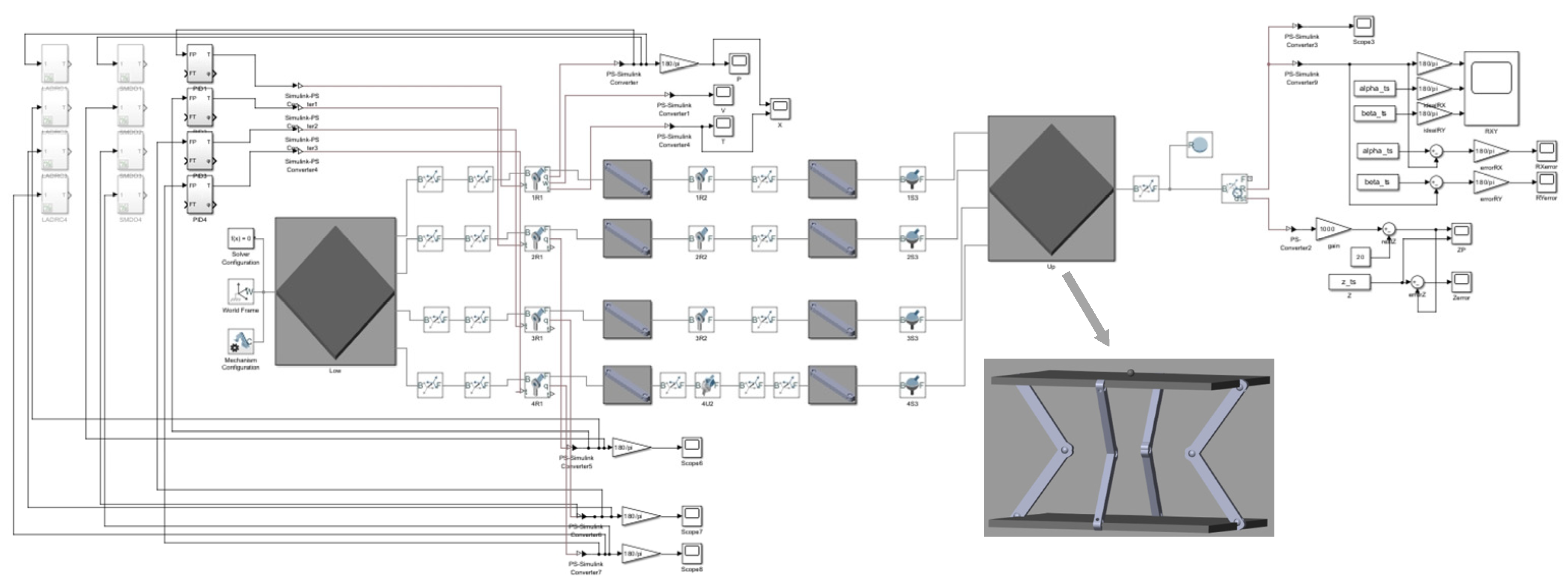
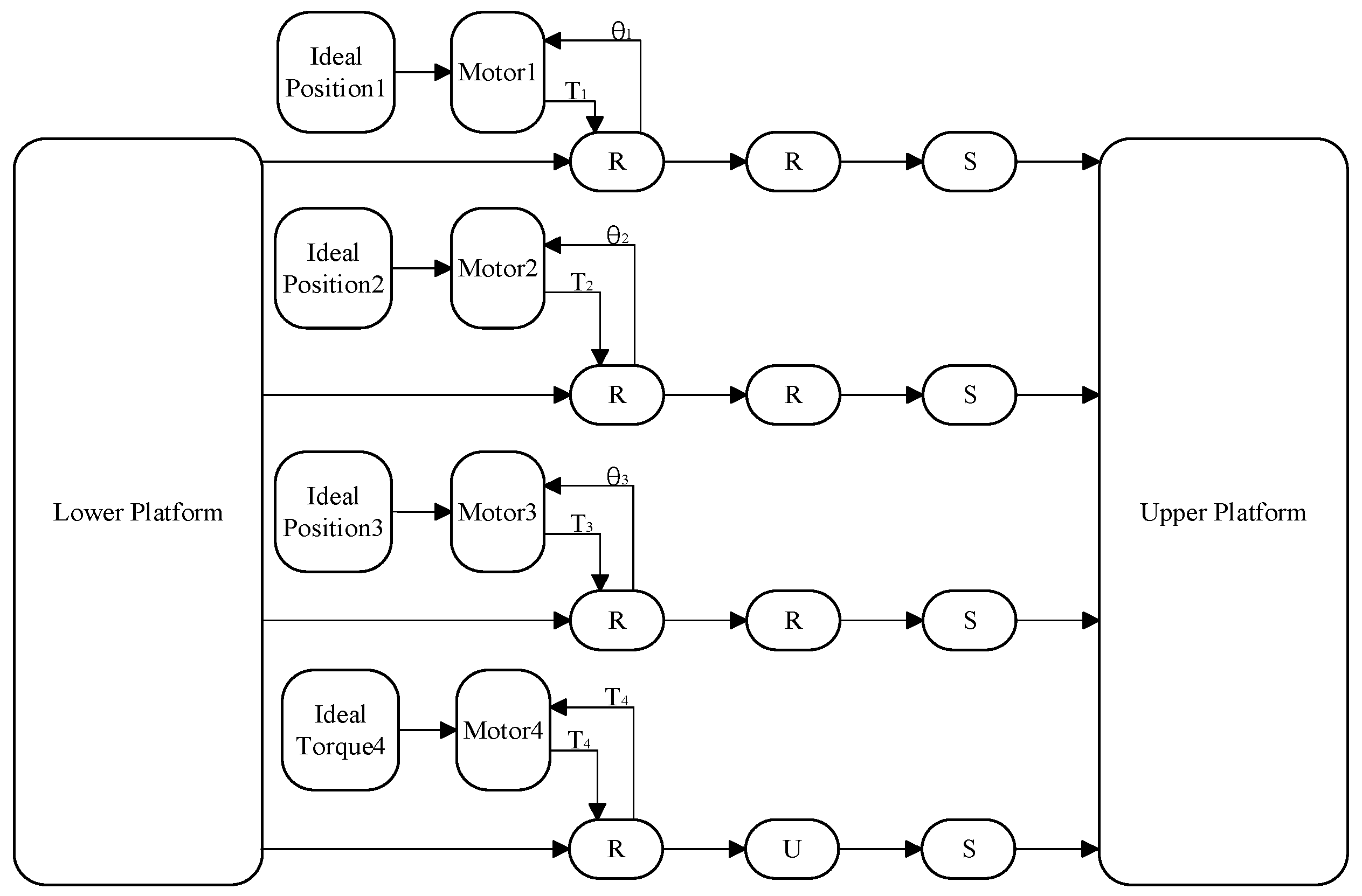
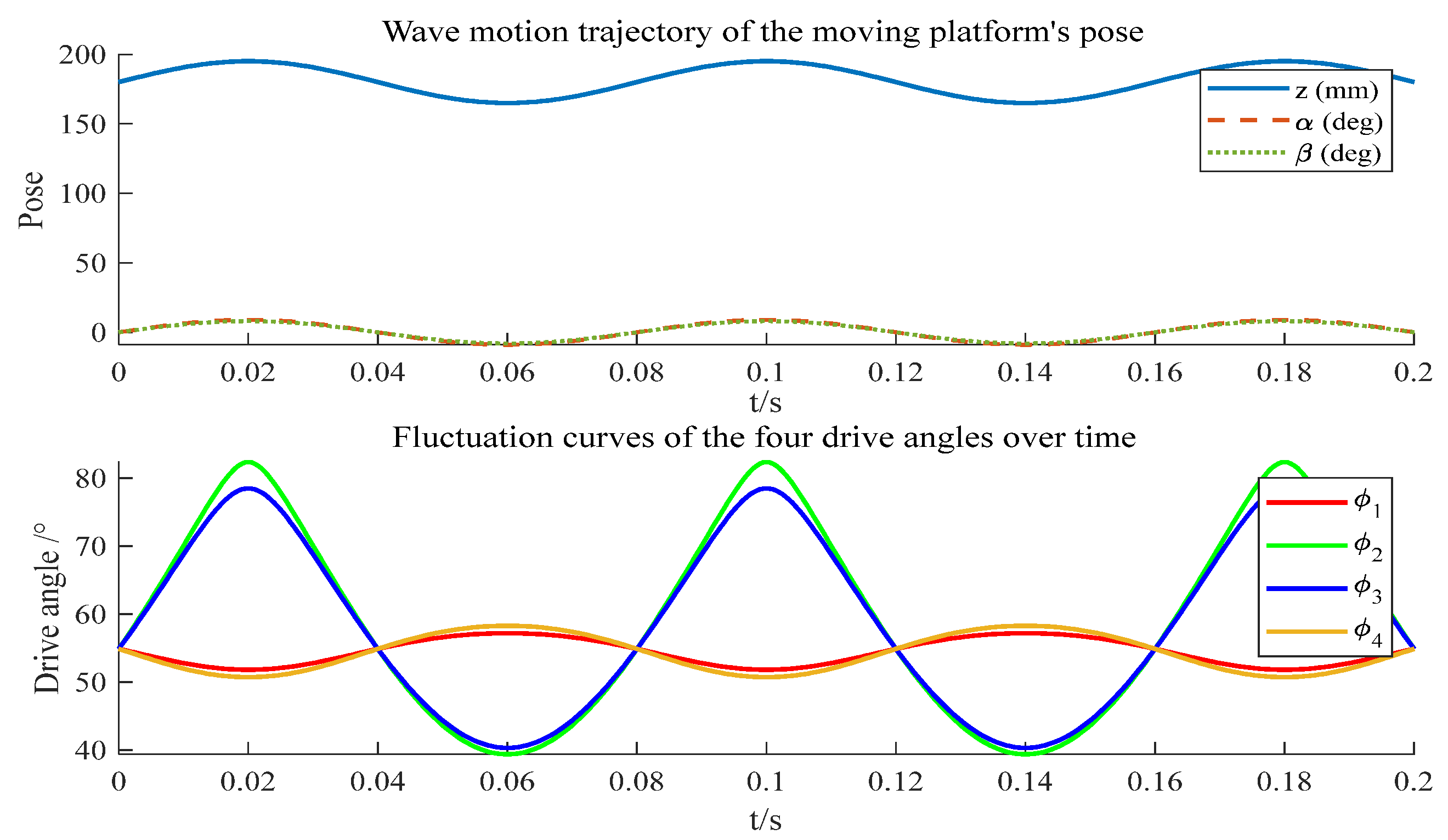
4. A simulation system of the 3RRS–RUS shipborne parallel stabilization platform is established in SimMechanics. The driving joint angles are obtained from the desired wave-induced motions of the moving platform through inverse kinematics and assigned to the servo motors. By applying output torque to the driving joints and feeding back joint angles to the motors, closed-loop control is realized. The simulation results demonstrate that the proposed SMDO–LADRC exhibits strong tracking performance, high robustness, and excellent disturbance rejection, and they further validate the feasibility of the designed three-degree-of-freedom 3RRS–RUS parallel stabilization platform.
2. Design and Kinematic Analysis of the 3RRS–RUS Parallel Mechanism
2.1. Type Synthesis of a 2R1T Asymmetric Three-Degree-of-Freedom Parallel Mechanism
In this section, type synthesis is conducted for the proposed 2R1T asymmetric three-degree-of-freedom parallel mechanism, aiming to achieve the following three-degree-of-freedom motion of the moving platform:
Translation along the Z-axis;
Rotation about the X- and Y-axes.
According to screw theory, the required basic motion screw system of the moving platform can be expressed as:
This motion screw system represents the spatial degrees of freedom required by the platform and constitutes its basic motion space
S:
According to the principle of screw reciprocity, the constraint screw system of the moving platform should be reciprocal to
S. The resulting constraint screw system is:
When the mechanism has
n branches, the constraint screw system of the moving platform is the maximal linearly independent set of the constraint screw systems of all serial branches:
Therefore, the constraint screw system of a serial branch can either be identical to that of the moving platform or a subset of it. By taking linear combinations of
,
,
, three new branch constraint screws are obtained:
Due to screw reciprocity, each branch of the 2R1T mechanism is reciprocal to one of the constraint screws. The motion screw systems reciprocal to these constraints can be expressed as:
Based on the obtained motion screw systems, each branch can be constructed accordingly. Various equivalent serial branches can be generated through different linear combinations or arrangements of the motion screws.
From Equation (10), this motion screw system represents a kinematic branch composed of five revolute joints, forming an RRRRR branch, while ensuring that the axes of the revolute joints are mutually parallel. Based on this, by considering the equivalence of compound joints such as a universal joint (U) equivalent to
, a spherical joint (S) equivalent to
, so additional branch mechanisms can be constructed. For example, in the aforementioned branch, if the axes of three revolute joints are mutually perpendicular, these three revolute joints can be equivalently represented as a spherical joint (S), transforming the motion branch into an SRR branch.
The remaining two branches can be treated similarly and are also equivalent to SRR branches. The branches described above represent only those relevant to the present study; by the same principle, additional related branch structures can be constructed.
By inverting the positions of the moving and fixed platforms, a 3-RRS mechanism is obtained.
To enhance the stiffness, stability, load-bearing capacity, and control accuracy of the mechanism, while ensuring that the platform attitude can be well maintained even if one branch becomes inoperative and preserving the 2R1T three degrees of freedom, an additional six-degree-of-freedom unconstrained redundant branch (RUS) is introduced to share the driving load. In this configuration, to ensure stable operation and improved precision, the three RRS branches are position-driven, while the RUS is force-driven. The compensating forces not only enhance the load-bearing capacity and control accuracy, but also compensate for backlash. Moreover, if one branch fails, the RUS helps maintain overall platform stability.
In summary, the 2R1T asymmetric three-degree-of-freedom parallel mechanism proposed in this study is designed as a 3RRS–RUS configuration.
2.2. Degree-of-Freedom Analysis of the 3RRS–RUS Parallel Mechanism Based on Screw Theory
The 3RRS–RUS parallel mechanism is composed of three identical RRS branches and one RUS. The center of the fixed platform is denoted as O
1, and the joint coordinates of each branch from bottom to top are represented as
Ai,
Bi, and
Ci, respectively. The directions of the joints at points
Ai,
Bi, and
Ci are denoted as
si. In this section, screw theory is applied to analyze the degrees of freedom (DOF) of the mechanism, and the modified G–K formula is used to validate the DOF calculation:
where
F—degrees of freedom (DOF) of the mechanism;
d—order of the mechanism;
n—total number of links in the mechanism;
g—number of kinematic pairs in the mechanism;
fi—degrees of freedom of the
ith kinematic pair;
v—redundant degrees of freedom of the mechanism;
ζ—local degrees of freedom of the mechanism.
The schematic diagram of the mechanism is shown in
Figure 1. From right to left, the mechanism consists of three identical RRS branches and one RUS, with all revolute joints oriented toward the center point of the moving platform. The fixed platform is connected to the four branches through revolute joints, while the moving platform is connected to the four branches through spherical joints. In the middle of branches 1, 2, and 3, the connections are established via revolute joints, whereas in branch 4 the connection is realized through a universal joint.
Both the fixed and moving platforms are square in shape, with side length 2a, and the height difference between them is denoted as h. Since the coordinates of point Bi may vary in space, they are defined as (Xi Yi Zi), subject to the condition X < a.
The coordinates of the kinematic pairs at points
A1,
A2,
A3 and
A4 are defined as follows:
The coordinates of the kinematic pairs at points
B1,
B2,
B3 and
B4 are defined as follows:
The coordinates of the kinematic pairs at points
C1,
C2,
C3 and
C4 are defined as follows:
Thus, in the initial configuration, the motion screw system
S of the RRS branch can be expressed as:
In the initial configuration, the motion screw system of the RUS can be expressed as follows:
According to the principle of reciprocal screws: (1) Two line vectors are reciprocal if and only if they are coplanar; if they are not coplanar, they cannot be reciprocal. (2) Two moments are always reciprocal. (3) A line vector and a moment are reciprocal only when they are perpendicular; if they are not perpendicular, they are not reciprocal. (4) Both line vectors and moments are self-reciprocal.
Based on screw reciprocity, the reciprocal screws of each branch, that is, the constraint screw systems, can be obtained as follows:
The motion screw system S4 of the RUS is full rank, and the dimension of its reciprocal screw space is zero; thus, it has no reciprocal screws.
Thus, the constraint screw system of the 3RRS–RUS parallel mechanism is given by:
Based on screw reciprocity, the motion screw system of the 3RRS–RUS parallel mechanism is given by:
This indicates that the 3RRS–RUS parallel mechanism possesses rotational degrees of freedom about axes parallel to the X- and Y-axes passing through the point (0 0
h), as well as a translational degree of freedom along the Z-axis, totaling three degrees of freedom. Therefore, the motion type of this parallel mechanism is two rotations and one translation (2R1T). The correctness of this DOF analysis is further validated using the modified G-K formula, as follows:
2.3. Parasitic Motion Analysis
Parasitic motion is a common characteristic of low-degree-of-freedom parallel mechanisms, primarily manifested as unintended movements of the moving platform resulting from continuous rotations about different axes.
Assume that the moving platform rotates by an angle
α about the X-axis. Let the actuated joints of branches 1 and 4 remain fixed, so that the motion screw systems of these branches are unchanged. The continuous rotation of the moving platform about the X-axis is then achieved through the motions of branches 2 and 4. Let the coordinates of point
B2’ be (0
Y2B Z2B), the coordinates of point
C2’ be (0
Y2C Z2C), the coordinates of point
B4’ be (0
Y4B Z4B) and the coordinates of point
C4’ be (0
Y4C Z4C). Then, the motion screw systems of branches 2 and 4 are given by:
Consequently, the constraint screw system of branch 2 is obtained as follows:
Since the motion screw system of branch 4 is full rank, the dimension of its reciprocal screw space is zero, and it has no reciprocal screws.
Similarly, assume that the moving platform rotates by an angle
β about the Y-axis. Let the coordinates of point
B1’ be (
X1B 0
Z1B), the coordinates of point
C1’ be (
X1C 0
Z1C), the coordinates of point
B3’ be (0
Y4B Z4B) and the coordinates of point
C3’ be (0
Y4C Z4C). Then, the motion screw systems of branches 1 and 3 are given by:
Consequently, the constraint screw system of branch 1 and 3 is obtained as follows:
Thus, the constraint screw system of the mechanism at this configuration is:
where
, and its form is the same as in Equation (19). At this point, the matrix is full rank with a rank of 3, indicating that the constraint screw system is linearly independent and can effectively constrain all three degrees of freedom.
Furthermore, as indicated by Equation (20), in the initial configuration, the motion output of the 2R1T parallel mechanism only includes translation along the Z-axis and rotations about the X- and Y-axes. Therefore, the platform eliminates parasitic rotation of the moving platform about the Z-axis as well as translations along the X- and Y-axes. Consequently, the designed 3RRS–RUS parallel mechanism exhibits no parasitic motion.
In future work, a physical prototype of the 3RRS–RUS shipborne stabilization platform will be developed and tested using a calibrated AHRS module and inertial measurement unit (IMU). This will serve as a crucial step toward the comprehensive verification and engineering application of the proposed platform.
2.4. Kinematics Analysis of the 3RRS-RUS Parallel Mechanism
To establish the position equations of the mechanism, it is first necessary to define the coordinate systems. A fixed coordinate system
O-XYZ is attached to the static platform, and a moving coordinate system
O’-X’Y’Z’ is attached to the moving platform, as shown in
Figure 1. Both the static and moving platforms are square in shape, each with a side length of 2
a. The actuated joints of the branches are located at the midpoints of the sides of the static platform, while the terminal joints are positioned at the midpoints of the sides of the moving platform. The origins of the static and moving coordinate systems are placed at the centers of their respective square platforms. Let the angle between the line segment
AiBi and the static platform be
φi. The length of the link
AiBi, which connects to the static platform, is denoted as
l1, and the length of the link
BiCi, which connects to the moving platform, is denoted as
l2.
Based on the established fixed coordinate system
O-XYZ, the position vector of point
Ai on the static platform can be expressed as:
Accordingly, the position vector of point
Bi is given by:
By introducing the moving coordinate system
O’-X’Y’Z’, the position vectors of the corresponding points on the moving platform can be obtained as:
The position vector of any point in the moving coordinate system can be transformed into the fixed coordinate system through a coordinate transformation, which can be expressed as:
Since the mechanism allows rotation about the X- and Y-axes as well as translation along the Z-axis, the corresponding rotation matrix can be written as:
Using the transformation relationship given in Equation (34), the position vector of point
Ci in the static coordinate system can be obtained as:
Based on the principle of constant link length, the following constraint equations can be derived:
Substituting the coordinate vectors into the constraint equations yields the following expressions:

