Article

Design of a Novel Shipborne Parallel Stabilization Platform and Control Strategy Based on Improved LADRC

1
School of Mechanical Engineering, Jiangsu University of Technology, Changzhou 213001, China
2
Jiangsu Provincial Engineering Research Center for Advanced Fluid Power and Equipment, Changzhou 213001, China
*
Author to whom correspondence should be addressed.
Actuators 2025, 14(11), 564; https://doi.org/10.3390/act14110564
Submission received: 13 October 2025 / Revised: 14 November 2025 / Accepted: 17 November 2025 / Published: 19 November 2025
(This article belongs to the Special Issue Design and Control of Parallel Robotics)

Abstract

To enhance the precision, load capacity, disturbance rejection, and reliability of shipborne parallel stabilization platforms under complex sea conditions, this paper proposes a redundant, actuated, parasitic-motion-free 3-DOF 3RRS-RUS parallel stabilization platform. Based on the proposed 3RRS-RUS shipborne parallel stabilization platform, a Linear Active Disturbance Rejection Control (LADRC) approach, integrated with a Sliding Mode Disturbance Observer (SMDO), is developed. First, the mechanism is synthesized using screw theory, and its 2R1T 3-DOF characteristics are verified through parasitic motion analysis. Second, the inverse kinematics model is established. Third, the conventional LADRC is decoupled, and a new Linear Extended State Observer (LESO) together with its corresponding control law is designed. Moreover, an SMDO is incorporated into the motor’s three-loop control scheme to alleviate the estimation burden on the LESO and enhance the system’s disturbance rejection capability. Finally, experimental validations were carried out on both the CSPACE and SimMechanics platforms. The results demonstrate that the proposed SMDO–LADRC achieves superior tracking performance, high robustness, and strong disturbance rejection capability, The tracking errors along the RX, RY, and Z axes were reduced by 6.5%, 1.1%, and 16.6%, respectively, compared with the conventional LADRC, while also confirming the feasibility of the newly designed 3-DOF 3RRS-RUS shipborne parallel stabilization platform.

1. Introduction

When a ship sails at sea, it is inevitably affected by environmental factors such as wind and waves, which induce complex motions in its attitude. These disturbances not only reduce the precision and efficiency of shipboard operations but also compromise the stability and reliability of onboard systems such as radars and electro-optical sensors. Consequently, the development of shipborne stabilization platforms capable of isolating the effects of hull motion has become an important research focus. Among various solutions, parallel mechanisms are widely adopted in such platforms due to their high stiffness, strong load-bearing capacity, and superior dynamic performance.
Ref. [1] proposed a novel six-degree-of-freedom (6-DOF) spatial parallel platform, in which three identical kinematic chains connect a five-bar linkage to the base. The study demonstrated that, by using only lightweight elastic components, such a structure can achieve effective static balancing. Ref. [2] introduced a redundantly actuated 6-DOF parallel mechanism with a partially decoupled rotational structure, enabling efficient real-time control and allowing full 360° rotational motion in six degrees of freedom. Ref. [3] developed a 3-PUU parallel mechanism with 2R1T degrees of freedom. With appropriate parameter settings, the 3-PUU mechanism can be applied to machining and pick-and-place operations. Ref. [4] presented a 5-PSS/UPU parallel mechanism, where five degrees of freedom can be adjusted in real time through a single actuated branch, thus maintaining dynamic balance. Ref. [5] designed a novel U-PRU-PUS parallel mechanism, whose tracking performance was improved through optimization of structural parameters. Ref. [6] proposed an improved six-degree-of-freedom hybrid serial–parallel platform for ship wave compensation. Comparative analysis with the Stewart platform showed that the proposed mechanism offers advantages in wave compensation performance.
Shipborne parallel stabilization platforms are highly nonlinear, strongly coupled, and multivariable dynamic systems. In unpredictable and stochastic ocean environments, they are subject to various loads and disturbances induced by ship oscillations. The system exhibits significant dynamic and disturbance uncertainties, which pose major challenges for control design. Ref. [7] proposed a sliding mode variable structure control (SMVSC) scheme based on the mathematical model of the control loop and the operational characteristics of shipborne weapon stabilization platforms (SPOSWs). Simulation results demonstrated that SMVSC not only satisfies static and dynamic performance requirements, but also significantly enhances system robustness and disturbance rejection. Ref. [8] developed a ship stabilization platform control strategy based on motion-prediction model predictive control (MPMPC). Both simulations and experiments confirmed that MPMPC achieves higher tracking accuracy than conventional MPC. Ref. [9] proposed a sliding mode control scheme for a shipborne Stewart platform, together with a novel velocity feedforward compensator to enhance control performance. A Lyapunov-based analysis rigorously proved the boundedness of the control error, and simulations further validated the effectiveness of the proposed approach. Ref. [10] introduced a wave-compensation triple-loop control strategy for shipborne Stewart platforms based on active disturbance rejection control (ADRC). The results showed that the method provides superior performance in power reduction, decoupling, and disturbance rejection. In the same year, ref. [11] also proposed a modal-space control strategy to address the low natural frequency and vibration susceptibility of parallel stabilization platforms. A modal-space sliding mode controller was designed, and simulations demonstrated its advantages in compensation accuracy and robustness against disturbances. Ref. [12] presented a robust backstepping sliding mode control (RBSMC) method. A Stewart platform simulation model was established, and results showed that the proposed approach effectively improved the compensation rate. Ref. [13] proposed a robust stabilization control method based on a proportional–triple extended state observer (PTESO), which estimates total disturbances including dynamic uncertainties, unknown time-varying external disturbances, and couplings among state variables. Comparative studies validated the effectiveness of the proposed strategy. Ref. [14] developed a BP neural network-based PID control algorithm, where the PID parameters are adaptively tuned by a backpropagation neural network. The simulation results indicated that, compared with conventional PID control, the proposed method achieves higher compensation accuracy along three directions under different sea conditions. Ref. [15] addressed the impact of complex sea states on landing platform stability and proposed a novel control compensation method. A recursive least-squares AR prediction algorithm was designed, and the experimental results demonstrated improvements in compensation accuracy of 59.6%, 60.3%, 48.4%, and 47.9%, respectively. Ref. [16] further proposed a composite control scheme based on inverse dynamics, incorporating an equivalent input disturbance (EID) method with robust feedback control to counteract unknown external disturbances. The experimental results showed that this approach outperforms several conventional methods in resisting both internal and external disturbances. Ref. [17] presented a model predictive control strategy for shipborne stabilization platforms that explicitly considers load disturbances. Both simulations and experiments verified that this method exhibits stronger robustness and disturbance rejection compared with traditional MPC. Finally, ref. [18] proposed a novel two-layer online adaptive predictive control strategy to address the time-varying parameters of electro-hydraulic servo systems under different operating conditions, strong coupling among platform actuators, and the randomness of ship motion. The results demonstrated that, compared with traditional single-layer MPC, the proposed two-layer approach significantly improves attitude compensation accuracy, dynamic response speed, system stability, and computational efficiency.
The core concept of active disturbance rejection control is to unify system uncertainties and external disturbances into a “total disturbance,” which is estimated and compensated in real time using an extended state observer. This approach reduces reliance on precise system modeling. To enhance engineering practicality, LADRC employs a linear extended state observer and a linear controller, thereby simplifying parameter tuning and significantly reducing implementation complexity while maintaining robustness. Ref. [19] introduced an improved ADRC controller for a 6-DOF parallel platform. Under disturbance conditions, the controller achieved precise trajectory tracking, and both simulation and experimental results verified its effectiveness in driving the 6-DOF platform to accurately realize the desired motions. Ref. [20] proposed a second-order LADRC applied to the velocity loop to enhance disturbance rejection, enabling the system to track targets stably and accurately. Simulation results demonstrated that adopting LADRC in the velocity loop significantly improves control performance and robustness against disturbances. Ref. [21] modeled the multi-loop structure of a servo system and designed a linear ADRC to enhance control performance and disturbance rejection. The results showed that the proposed method achieves better control effects and stronger robustness compared with conventional approaches. Ref. [22] developed an improved ADRC based on particle swarm optimization (PSO), which simplified the controller structure and reduced the number of parameters requiring manual tuning. By further optimizing the parameters through PSO, the improved ADRC exhibited reduced overshoot, faster response, higher accuracy, and stronger disturbance rejection compared with a traditional PID controller, thereby demonstrating superior reliability and robustness. Ref. [23] addressed the insufficient disturbance suppression capability of conventional ADRC in stabilization platforms by proposing a VGD-ADRC method. Results indicated that VGD-ADRC effectively eliminates overshoot, improves noise suppression, and enhances tracking accuracy in stabilization platforms.
In this work, a novel shipborne parallel stabilization platform with a 3RRS–RUS configuration is designed, and a motor-based three-loop control strategy based on SMDO–LADRC is proposed. Finally, simulations and experiments are conducted to demonstrate its strong robustness and disturbance rejection capabilities. The main innovations and contributions of this study are summarized as follows and a comparison between the proposed mechanism and the conventional Stewart platform is summarized in Table 1.
1. A novel 2R1T asymmetric three-degree-of-freedom redundant parallel mechanism, the 3RRS–RUS shipborne stabilization platform, is designed through type synthesis. Its feasibility is verified through degrees-of-freedom analysis, evaluation of parasitic motions, and kinematic analysis.
2. The traditional LADRC is derived and decoupled, and a new extended state observer and control law are designed. A sliding-mode disturbance observer is introduced to estimate the total system disturbance. The observed disturbance is incorporated into the LESO state equations as a compensation term, allowing the LESO to monitor only the residual disturbance. This approach not only reduces the observation burden on the LESO but also improves disturbance estimation accuracy and enhances closed-loop disturbance rejection performance.
3. Three-loop control experiments on the servo motor are conducted using the Control signal process and control engineering (CSPACE) hardware-in-the-loop simulation platform. The experimental results are analyzed through Fourier transforms and Bode plots. The results indicate that the proposed SMDO–LADRC system achieves asymptotic stability and higher control accuracy.
4. A simulation system of the 3RRS–RUS shipborne parallel stabilization platform is established in SimMechanics. The driving joint angles are obtained from the desired wave-induced motions of the moving platform through inverse kinematics and assigned to the servo motors. By applying output torque to the driving joints and feeding back joint angles to the motors, closed-loop control is realized. The simulation results demonstrate that the proposed SMDO–LADRC exhibits strong tracking performance, high robustness, and excellent disturbance rejection, and they further validate the feasibility of the designed three-degree-of-freedom 3RRS–RUS parallel stabilization platform.

2. Design and Kinematic Analysis of the 3RRS–RUS Parallel Mechanism

2.1. Type Synthesis of a 2R1T Asymmetric Three-Degree-of-Freedom Parallel Mechanism

In this section, type synthesis is conducted for the proposed 2R1T asymmetric three-degree-of-freedom parallel mechanism, aiming to achieve the following three-degree-of-freedom motion of the moving platform:
Translation along the Z-axis;
Rotation about the X- and Y-axes.
According to screw theory, the required basic motion screw system of the moving platform can be expressed as:
$ 1 = [ 1 0 0 ; 0 0 0 ] , $ 2 = [ 0 1 0 ; 0 0 0 ] , $ 3 = [ 0 0 0 ; 0 0 1 ] .
This motion screw system represents the spatial degrees of freedom required by the platform and constitutes its basic motion space S:
S = $ 1 $ 2 $ 3 = 1 0 0 ; 0 0 0 0 1 0 ; 0 0 0 0 0 0 ; 0 0 1 ,   dim ( S ) = 3 .
According to the principle of screw reciprocity, the constraint screw system of the moving platform should be reciprocal to S. The resulting constraint screw system is:
$ 1 r = [ 1 0 0 ; 0 0 0 ] , $ 2 r = [ 0 1 0 ; 0 0 0 ] , $ 3 r = [ 0 0 0 ; 0 0 1 ] ,
S r = $ 1 r $ 2 r $ 3 r = 1 0 0 ; 0 0 0 0 1 0 ; 0 0 0 0 0 0 ; 0 0 1 ,   dim ( S r ) = 3 .
When the mechanism has n branches, the constraint screw system of the moving platform is the maximal linearly independent set of the constraint screw systems of all serial branches:
S r S i r .
Therefore, the constraint screw system of a serial branch can either be identical to that of the moving platform or a subset of it. By taking linear combinations of $ 1 r , $ 2 r , $ 3 r , three new branch constraint screws are obtained:
S 1 r = $ 1 r + $ 3 r = [ 1 0 0 ; 0 0 1 ] , S 2 r = $ 2 r + $ 3 r = [ 0 1 0 ; 0 0 1 ] , S 3 r = $ 2 r + $ 3 r = [ 0 1 0 ; 0 0 1 ] .
Due to screw reciprocity, each branch of the 2R1T mechanism is reciprocal to one of the constraint screws. The motion screw systems reciprocal to these constraints can be expressed as:
S 1 = $ 1 , 1 = [ 1 0 0 ; 0 0 0 ] $ 1 , 2 = [ 0 1 0 ; 0 0 0 ] $ 1 , 3 = [ 0 0 1 ; 1 0 0 ] $ 1 , 4 = [ 0 0 0 ; 0 1 0 ] $ 1 , 5 = [ 0 0 0 ; 0 0 1 ] ,
S 2 = $ 2 , 1 = [ 1 0 0 ; 0 0 0 ] $ 2 , 2 = [ 0 1 0 ; 0 0 0 ] $ 2 , 3 = [ 0 0 1 ; 0 1 0 ] $ 2 , 4 = [ 0 0 0 ; 1 0 0 ] $ 2 , 5 = [ 0 0 0 ; 0 0 1 ] ,
S 3 = $ 3 , 1 = [ 1 0 0 ; 0 0 0 ] $ 3 , 2 = [ 0 1 0 ; 0 0 0 ] $ 3 , 3 = [ 0 0 1 ; 0 1 0 ] $ 3 , 4 = [ 0 0 0 ; 1 0 0 ] $ 3 , 5 = [ 0 0 0 ; 0 0 1 ] .
Based on the obtained motion screw systems, each branch can be constructed accordingly. Various equivalent serial branches can be generated through different linear combinations or arrangements of the motion screws.
S 1 = $ 1 , 1 = [ 1 0 0 ; 0 0 0 ] $ 1 , 2 = [ 0 1 0 ; 0 0 0 ] $ 1 , 3 = [ 0 0 1 ; 1 0 0 ] $ 1 , 4 = $ 1 , 1 + q 14 $ 1 , 4 = [ 1 0 0 ; 0 q 14 0 ] $ 1 , 5 = $ 1 , 1 + r 15 $ 1 , 5 = [ 1 0 0 ; 0 0 r 15 ] .
From Equation (10), this motion screw system represents a kinematic branch composed of five revolute joints, forming an RRRRR branch, while ensuring that the axes of the revolute joints are mutually parallel. Based on this, by considering the equivalence of compound joints such as a universal joint (U) equivalent to R R , a spherical joint (S) equivalent to R R R , so additional branch mechanisms can be constructed. For example, in the aforementioned branch, if the axes of three revolute joints are mutually perpendicular, these three revolute joints can be equivalently represented as a spherical joint (S), transforming the motion branch into an SRR branch.
S 2 = $ 2 , 1 = [ 1 0 0 ; 0 0 0 ] $ 2 , 2 = [ 0 1 0 ; 0 0 0 ] $ 2 , 3 = [ 0 0 1 ; 0 1 0 ] $ 2 , 4 = $ 2 , 2 + p 24 $ 2 , 4 = [ 0 1 0 ; p 24 0 0 ] $ 2 , 5 = $ 2 , 2 + r 25 $ 2 , 5 = [ 0 1 0 ; 0 0 r 25 ] ,
S 3 = $ 3 , 1 = [ 1 0 0 ; 0 0 0 ] $ 3 , 2 = [ 0 1 0 ; 0 0 0 ] $ 3 , 3 = [ 0 0 1 ; 0 1 0 ] $ 3 , 4 = $ 3 , 2 + p 34 $ 3 , 4 = [ 0 1 0 ; p 34 0 0 ] $ 3 , 5 = $ 3 , 2 + r 35 $ 3 , 5 = [ 0 1 0 ; 0 0 r 35 ] .
The remaining two branches can be treated similarly and are also equivalent to SRR branches. The branches described above represent only those relevant to the present study; by the same principle, additional related branch structures can be constructed.
By inverting the positions of the moving and fixed platforms, a 3-RRS mechanism is obtained.
To enhance the stiffness, stability, load-bearing capacity, and control accuracy of the mechanism, while ensuring that the platform attitude can be well maintained even if one branch becomes inoperative and preserving the 2R1T three degrees of freedom, an additional six-degree-of-freedom unconstrained redundant branch (RUS) is introduced to share the driving load. In this configuration, to ensure stable operation and improved precision, the three RRS branches are position-driven, while the RUS is force-driven. The compensating forces not only enhance the load-bearing capacity and control accuracy, but also compensate for backlash. Moreover, if one branch fails, the RUS helps maintain overall platform stability.
In summary, the 2R1T asymmetric three-degree-of-freedom parallel mechanism proposed in this study is designed as a 3RRS–RUS configuration.

2.2. Degree-of-Freedom Analysis of the 3RRS–RUS Parallel Mechanism Based on Screw Theory

The 3RRS–RUS parallel mechanism is composed of three identical RRS branches and one RUS. The center of the fixed platform is denoted as O1, and the joint coordinates of each branch from bottom to top are represented as Ai, Bi, and Ci, respectively. The directions of the joints at points Ai, Bi, and Ci are denoted as si. In this section, screw theory is applied to analyze the degrees of freedom (DOF) of the mechanism, and the modified G–K formula is used to validate the DOF calculation:
F = d ( n g 1 ) + i = 1 g f i + v ζ ,
where F—degrees of freedom (DOF) of the mechanism; d—order of the mechanism; n—total number of links in the mechanism; g—number of kinematic pairs in the mechanism; fi—degrees of freedom of the ith kinematic pair; v—redundant degrees of freedom of the mechanism; ζ—local degrees of freedom of the mechanism.
The schematic diagram of the mechanism is shown in Figure 1. From right to left, the mechanism consists of three identical RRS branches and one RUS, with all revolute joints oriented toward the center point of the moving platform. The fixed platform is connected to the four branches through revolute joints, while the moving platform is connected to the four branches through spherical joints. In the middle of branches 1, 2, and 3, the connections are established via revolute joints, whereas in branch 4 the connection is realized through a universal joint.
Both the fixed and moving platforms are square in shape, with side length 2a, and the height difference between them is denoted as h. Since the coordinates of point Bi may vary in space, they are defined as (Xi Yi Zi), subject to the condition X < a.
The coordinates of the kinematic pairs at points A1, A2, A3 and A4 are defined as follows:
s 1 , 1 = [ a   0   0 ] ; s 2 , 1 = [ 0   a   0 ] ; s 3 , 1 = [ a   0   0 ] ; s 4 , 1 = [ 0   a   0 ] ;
The coordinates of the kinematic pairs at points B1, B2, B3 and B4 are defined as follows:
s 1 , 2 = [ X 1   0   Z 1 ] ; s 2 , 2 = [ 0   Y 2   Z 2 ] ; s 3 , 2 = [ X 3   0   Z 3 ] ; s 4 , 2 = [ 0   Y 4   Z 4 ] ;
The coordinates of the kinematic pairs at points C1, C2, C3 and C4 are defined as follows:
s 1 , 3 = [ a   0   h ] ; s 2 , 3 = [ 0   a   h ] ; s 3 , 3 = [ a   0   h ] ; s 4 , 3 = [ 0   a   h ] ;
Thus, in the initial configuration, the motion screw system S of the RRS branch can be expressed as:
S 1 = $ 1 , 1 = [ 0 1 0 ; s 1 , 1 × ( 0 1 0 ) ] T $ 1 , 2 = [ 0 1 0 ; s 1 , 2 × ( 0 1 0 ) ] T $ 1 , 3 = [ 1 0 0 ; s 1 , 3 × ( 1 0 0 ) ] T $ 1 , 4 = [ 0 1 0 ; s 1 , 3 × ( 0 1 0 ) ] T $ 1 , 5 = [ 0 0 1 ; s 1 , 3 × ( 0 0 1 ) ] T = $ 1 , 1 = [ 0 1 0 ; 0 0 a ] T $ 1 , 2 = [ 0 1 0 ; Z 1 0 X 1 ] T $ 1 , 3 = [ 1 0 0 ; 0 h 0 ] T $ 1 , 4 = [ 0 1 0 ; h 0 a ] T $ 1 , 5 = [ 0 0 1 ; 0 a 0 ] T ,
S 2 = $ 2 , 1 = [ 1 0 0 ; s 2 , 1 × ( 1 0 0 ) ] T $ 2 , 2 = [ 1 0 0 ; s 2 , 2 × ( 1 0 0 ) ] T $ 2 , 3 = [ 1 0 0 ; s 2 , 3 × ( 1 0 0 ) ] T $ 2 , 4 = [ 0 1 0 ; s 2 , 3 × ( 0 1 0 ) ] T $ 2 , 5 = [ 0 0 1 ; s 2 , 3 × ( 0 0 1 ) ] T = $ 2 , 1 = [ 1 0 0 ; 0 0 a ] T $ 2 , 2 = [ 1 0 0 ; 0 Z 2 Y 2 ] T $ 2 , 3 = [ 1 0 0 ; 0 h a ] T $ 2 , 4 = [ 0 1 0 ; h 0 0 ] T $ 2 , 5 = [ 0 0 1 ; a 0 0 ] T ,
S 3 = $ 3 , 1 = [ 0 1 0 ; s 3 , 1 × ( 0 1 0 ) ] T $ 3 , 2 = [ 0 1 0 ; s 3 , 2 × ( 0 1 0 ) ] T $ 3 , 3 = [ 1 0 0 ; s 3 , 3 × ( 1 0 0 ) ] T $ 3 , 4 = [ 0 1 0 ; s 3 , 3 × ( 0 1 0 ) ] T $ 3 , 5 = [ 0 0 1 ; s 3 , 3 × ( 0 0 1 ) ] T = $ 3 , 1 = [ 0 1 0 ; 0 0 a ] T $ 3 , 2 = [ 0 1 0 ; Z 3 0 X 3 ] T $ 3 , 3 = [ 1 0 0 ; 0 h 0 ] T $ 3 , 4 = [ 0 1 0 ; h 0 a ] T $ 3 , 5 = [ 0 0 1 ; 0 a 0 ] T .
In the initial configuration, the motion screw system of the RUS can be expressed as follows:
S 4 = $ 4 , 1 = [ 1 0 0 ; s 4 , 1 × ( 1 0 0 ) ] T $ 4 , 2 = [ 1 0 0 ; s 4 , 2 × ( 1 0 0 ) ] T $ 4 , 3 = [ 0 1 0 ; s 4 , 2 × ( 0 1 0 ) ] T $ 4 , 4 = [ 1 0 0 ; s 4 , 3 × ( 1 0 0 ) ] T $ 4 , 5 = [ 0 1 0 ; s 4 , 3 × ( 0 1 0 ) ] T $ 4 , 6 = [ 0 0 1 ; s 4 , 3 × ( 0 0 1 ) ] T = $ 4 , 1 = [ 1 0 0 ; 0 0 a ] T $ 4 , 2 = [ 1 0 0 ; 0 Z 4 Y 4 ] T $ 4 , 3 = [ 0 1 0 ; Z 4 0 0 ] T $ 4 , 4 = [ 1 0 0 ; 0 h a ] T $ 4 , 5 = [ 0 1 0 ; h 0 0 ] T $ 4 , 6 = [ 0 0 1 ; a 0 0 ] T .
According to the principle of reciprocal screws: (1) Two line vectors are reciprocal if and only if they are coplanar; if they are not coplanar, they cannot be reciprocal. (2) Two moments are always reciprocal. (3) A line vector and a moment are reciprocal only when they are perpendicular; if they are not perpendicular, they are not reciprocal. (4) Both line vectors and moments are self-reciprocal.
Based on screw reciprocity, the reciprocal screws of each branch, that is, the constraint screw systems, can be obtained as follows:
S 1 r = [ 0 1 0 ; h 0 a ] T , S 2 r = [ 1 0 0 ; 0 h a ] T , S 3 r = [ 0 1 0 ; h 0 a ] T .
The motion screw system S4 of the RUS is full rank, and the dimension of its reciprocal screw space is zero; thus, it has no reciprocal screws.
Thus, the constraint screw system of the 3RRS–RUS parallel mechanism is given by:
S r = 0 1 0 ; h 0 a 1 0 0 ; 0 h a 0 1 0 ; h 0 a T .
Based on screw reciprocity, the motion screw system of the 3RRS–RUS parallel mechanism is given by:
S = 1 0 0 ; 0 h 0 0 1 0 ; h 0 0 0 0 0 ; 0 0 1 T .
This indicates that the 3RRS–RUS parallel mechanism possesses rotational degrees of freedom about axes parallel to the X- and Y-axes passing through the point (0 0 h), as well as a translational degree of freedom along the Z-axis, totaling three degrees of freedom. Therefore, the motion type of this parallel mechanism is two rotations and one translation (2R1T). The correctness of this DOF analysis is further validated using the modified G-K formula, as follows:
F = d ( n g 1 ) + i = 1 g f i + v ζ = 6 ( 10 12 1 ) + 21 = 3 .

2.3. Parasitic Motion Analysis

Parasitic motion is a common characteristic of low-degree-of-freedom parallel mechanisms, primarily manifested as unintended movements of the moving platform resulting from continuous rotations about different axes.
Assume that the moving platform rotates by an angle α about the X-axis. Let the actuated joints of branches 1 and 4 remain fixed, so that the motion screw systems of these branches are unchanged. The continuous rotation of the moving platform about the X-axis is then achieved through the motions of branches 2 and 4. Let the coordinates of point B2 be (0 Y2B Z2B), the coordinates of point C2 be (0 Y2C Z2C), the coordinates of point B4 be (0 Y4B Z4B) and the coordinates of point C4 be (0 Y4C Z4C). Then, the motion screw systems of branches 2 and 4 are given by:
S 2 = $ 2 , 1 = [ 1 0 0 ; A 2 × ( 1 0 0 ) ] T $ 2 , 2 = [ 1 0 0 ; B 2 × ( 1 0 0 ) ] T $ 2 , 3 = [ 1 0 0 ; C 2 × ( 1 0 0 ) ] T $ 2 , 4 = [ 0 cos α sin α ; C 2 × ( 0 cos α sin α ) ] T $ 2 , 5 = [ 0 sin α cos α ; C 2 × ( 0 sin α cos α ) ] T = $ 2 , 1 = [ 1 0 0 ; 0 0 a ] T $ 2 , 2 = [ 1 0 0 ; 0 Z 2 B Y 2 B ] T $ 2 , 3 = [ 1 0 0 ; 0 Z 2 C Y 2 C ] T $ 2 , 4 = [ 0 cos α sin α ; Y 2 C sin α Z 2 C cos α 0 0 ] T $ 2 , 5 = [ 0 sin α cos α ; Y 2 C cos α + Z 2 C sin α 0 0 ] T ,
S 4 = $ 4 , 1 = [ 1 0 0 ; A 4 × ( 1 0 0 ) ] T $ 4 , 2 = [ 1 0 0 ; B 4 × ( 1 0 0 ) ] T $ 4 , 3 = [ 0 1 0 ; B 4 × ( 0 1 0 ) ] T $ 4 , 4 = [ 1 0 0 ; C 4 × ( 1 0 0 ) ] T $ 4 , 5 = [ 0 cos α sin α ; C 4 × ( 0 cos α sin α ) ] T $ 4 , 6 = [ 0 sin α cos α ; C 4 × ( 0 sin α cos α ) ] T = $ 4 , 1 = [ 1 0 0 ; 0 0 a ] T $ 4 , 2 = [ 1 0 0 ; 0 Z 4 B Y 4 B ] T $ 4 , 3 = [ 0 1 0 ; Z 4 B 0 0 ] T $ 4 , 4 = [ 1 0 0 ; 0 Z 4 C Y 4 C ] T $ 4 , 5 = [ 0 cos α sin α ; Y 4 C sin α Z 4 C cos α 0 0 ] T $ 4 , 6 = [ 0 sin α cos α ; Y 4 C cos α + Z 4 C sin α 0 0 ] T .
Consequently, the constraint screw system of branch 2 is obtained as follows:
S 2 r = [ 1 0 0 ; 0 Z 2 C Y 2 C ] T .
Since the motion screw system of branch 4 is full rank, the dimension of its reciprocal screw space is zero, and it has no reciprocal screws.
Similarly, assume that the moving platform rotates by an angle β about the Y-axis. Let the coordinates of point B1 be (X1B 0 Z1B), the coordinates of point C1 be (X1C 0 Z1C), the coordinates of point B3 be (0 Y4B Z4B) and the coordinates of point C3 be (0 Y4C Z4C). Then, the motion screw systems of branches 1 and 3 are given by:
S 1 = $ 1 , 1 = [ 0 1 0 ; A 1 × ( 0 1 0 ) ] T $ 1 , 2 = [ 0 1 0 ; B 1 × ( 0 1 0 ) ] T $ 1 , 3 = [ cos β 0 sin β ; C 1 × ( cos β 0 sin β ) ] T $ 1 , 4 = [ 0 1 0 ; C 1 × ( 0 1 0 ) ] T $ 1 , 5 = [ sin β 0 cos β ; C 1 × ( sin β 0 cos β ) ] T = $ 1 , 1 = [ 0 1 0 ; 0 0 a ] T $ 1 , 2 = [ 0 1 0 ; Z 1 B 0 X 1 B ] T $ 1 , 3 = [ cos β 0 sin β ; 0 Z 1 C cos β + X 1 C sin β 0 ] T $ 1 , 4 = [ 0 1 0 ; Z 1 C 0 X 1 C ] T $ 1 , 5 = [ sin β 0 cos β ; 0 Z 1 C sin β X 1 C cos β 0 ] T ,
S 3 = $ 3 , 1 = [ 0 1 0 ; A 3 × ( 0 1 0 ) ] T $ 3 , 2 = [ 0 1 0 ; B 3 × ( 0 1 0 ) ] T $ 3 , 3 = [ cos β 0 sin β ; C 3 × ( cos β 0 sin β ) ] T $ 3 , 4 = [ 0 1 0 ; C 3 × ( 0 1 0 ) ] T $ 3 , 5 = [ sin β 0 cos β ; C 3 × ( sin β 0 cos β ) ] T = $ 3 , 1 = [ 0 1 0 ; 0 0 a ] T $ 3 , 2 = [ 0 1 0 ; Z 3 B 0 X 3 B ] T $ 3 , 3 = [ cos β 0 sin β ; 0 Z 3 C cos β + X 3 C sin β 0 ] T $ 3 , 4 = [ 0 1 0 ; Z 3 C 0 X 3 C ] T $ 3 , 5 = [ sin β 0 cos β ; 0 Z 3 C sin β X 3 C cos β 0 ] T .
Consequently, the constraint screw system of branch 1 and 3 is obtained as follows:
S 1 r = [ 0 1 0 ; Z 1 C 0 X 1 C ] T ,
S 3 r = [ 0 1 0 ; Z 3 C 0 X 3 C ] T .
Thus, the constraint screw system of the mechanism at this configuration is:
S r = 0 1 0 ; Z 1 C 0 X 1 C 1 0 0 ; 0 Z 2 C Y 2 C 0 1 0 ; Z 3 C 0 X 3 C T ,
where Z 1 C Z 3 C , X 1 C X 3 C , and its form is the same as in Equation (19). At this point, the matrix is full rank with a rank of 3, indicating that the constraint screw system is linearly independent and can effectively constrain all three degrees of freedom.
Furthermore, as indicated by Equation (20), in the initial configuration, the motion output of the 2R1T parallel mechanism only includes translation along the Z-axis and rotations about the X- and Y-axes. Therefore, the platform eliminates parasitic rotation of the moving platform about the Z-axis as well as translations along the X- and Y-axes. Consequently, the designed 3RRS–RUS parallel mechanism exhibits no parasitic motion.
In future work, a physical prototype of the 3RRS–RUS shipborne stabilization platform will be developed and tested using a calibrated AHRS module and inertial measurement unit (IMU). This will serve as a crucial step toward the comprehensive verification and engineering application of the proposed platform.

2.4. Kinematics Analysis of the 3RRS-RUS Parallel Mechanism

To establish the position equations of the mechanism, it is first necessary to define the coordinate systems. A fixed coordinate system O-XYZ is attached to the static platform, and a moving coordinate system O’-X’Y’Z’ is attached to the moving platform, as shown in Figure 1. Both the static and moving platforms are square in shape, each with a side length of 2a. The actuated joints of the branches are located at the midpoints of the sides of the static platform, while the terminal joints are positioned at the midpoints of the sides of the moving platform. The origins of the static and moving coordinate systems are placed at the centers of their respective square platforms. Let the angle between the line segment AiBi and the static platform be φi. The length of the link AiBi, which connects to the static platform, is denoted as l1, and the length of the link BiCi, which connects to the moving platform, is denoted as l2.
Based on the established fixed coordinate system O-XYZ, the position vector of point Ai on the static platform can be expressed as:
A 1 o = ( a 0 0 ) T A 2 o = ( 0 a 0 ) T A 3 o = ( a 0 0 ) T A 4 o = ( 0 a 0 ) T .
Accordingly, the position vector of point Bi is given by:
B 1 o = ( a l 1 cos φ 1 0 l 1 sin φ 1 ) T B 2 o = ( 0 a l 1 cos φ 2 l 1 sin φ 2 ) T B 3 o = ( l 1 cos φ 3 a 0 l 1 sin φ 3 ) T B 4 o = ( 0 l 1 cos φ 4 a l 1 sin φ 4 ) T .
By introducing the moving coordinate system O’-X’Y’Z’, the position vectors of the corresponding points on the moving platform can be obtained as:
C 1 o = ( a 0 0 ) T C 2 o = ( 0 a 0 ) T C 3 o = ( a 0 0 ) T C 4 o = ( 0 a 0 ) T .
The position vector of any point in the moving coordinate system can be transformed into the fixed coordinate system through a coordinate transformation, which can be expressed as:
C i o = T C i o .
Since the mechanism allows rotation about the X- and Y-axes as well as translation along the Z-axis, the corresponding rotation matrix can be written as:
T = R o o O o o 0 1 = cos β sin β sin γ sin β cos γ 0 0 cos γ sin γ 0 sin β cos β sin γ cos β cos γ z 0 0 0 1 .
Using the transformation relationship given in Equation (34), the position vector of point Ci in the static coordinate system can be obtained as:
C 1 o = ( a cos β 0 z a sin β ) T C 2 o = ( a sin β sin γ a cos γ z + a cos β sin γ ) T C 3 o = ( a cos β 0 z + a sin β ) T C 4 o = ( a sin β sin γ a cos γ z a cos β sin γ ) T .
Based on the principle of constant link length, the following constraint equations can be derived:
B i C i = l 2 .
Substituting the coordinate vectors into the constraint equations yields the following expressions:
( a cos β a + l 1 cos φ 1 ) 2 + 0 2 + ( z a sin β l 1 sin φ 1 ) 2 = l 2 2 ( a sin β sin γ ) 2 + ( a cos γ a + l 1 cos φ 2 ) 2 + ( z + a cos β sin γ l 1 sin φ 2 ) 2 = l 2 2 ( a cos β + a l 1 cos φ 3 ) 2 + 0 2 + ( z + a sin β l 1 sin φ 3 ) 2 = l 2 2 ( a sin β sin γ ) 2 + ( a cos γ + a l 1 cos φ 4 ) 2 + ( z a cos β sin γ l 1 sin φ 4 ) 2 = l 2 2

3. Servo Controller Design Based on LADRC

3.1. Design of Linear Active Disturbance Rejection Controller

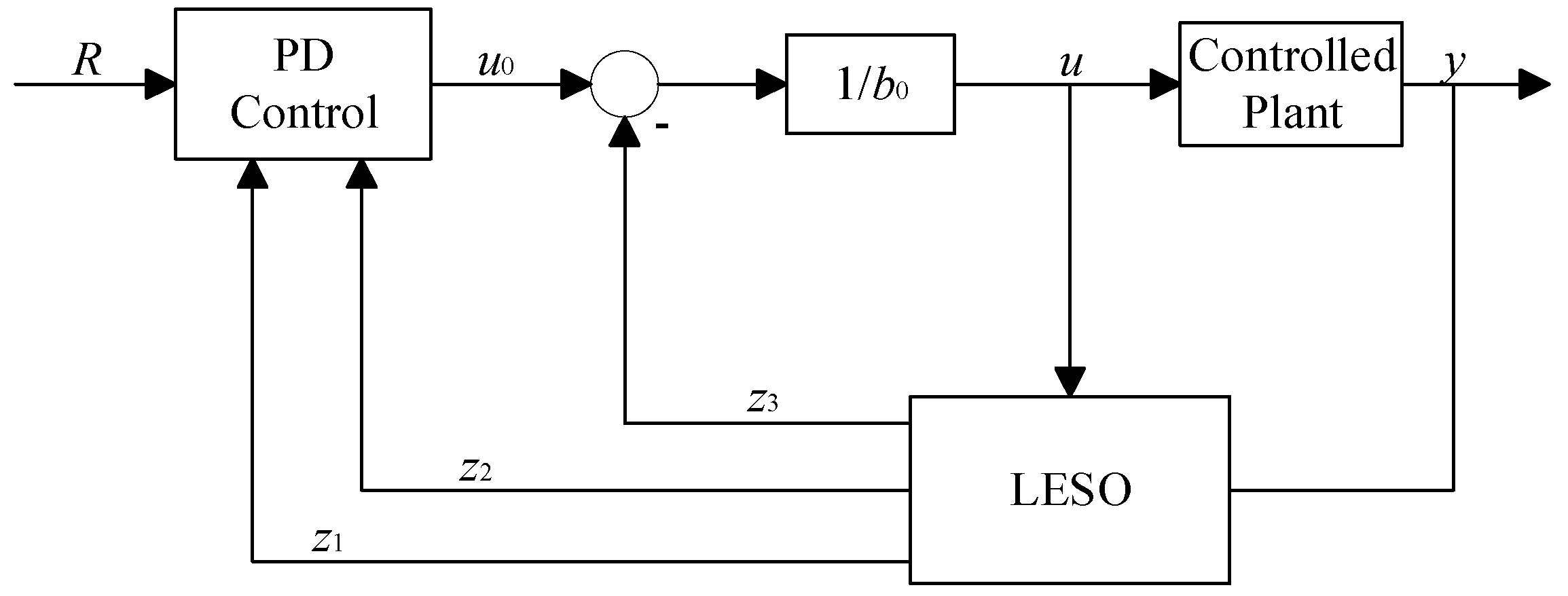
The fundamental concept of linear ADRC (LADRC) is to linearize the extended state observer (ESO) and relate its parameters to the observer bandwidth, thereby simplifying the design of the ESO. A simple PD control structure is adopted, with the proportional gain and derivative time constant linked to the controller bandwidth, which simplifies the tuning process. The simplified LADRC structure is illustrated in Figure 2.
Let the controlled plant be a second-order system with disturbances, described by the differential equation:
y ¨ = f y , y ˙ , ω , t + b u = a 1 y ˙ a 0 y + ω + b u .
In Equation (38), y and u represent the output and input, respectively, and ω denotes the disturbance. The parameters a1, a0, and ω are all unknown, while the known portion of b is denoted as b0. Therefore, Equation (38) can be rewritten as:
y ¨ = a 1 y ˙ a 0 y + ω + b b 0 u + b 0 u = f + b 0 u ,
where f = e 1 y ˙ e 0 y + ω + b b 0 u , represents the total disturbance, encompassing both external and internal disturbances.
By selecting the state variable x 1 = y ,   x 2 = y ˙ ,   x 3 = f , the expanded state x = y y ˙ f T , includes the disturbance. Thus, Equation (39) can be transformed into a continuous expanded state-space representation:
x ˙ = A x + B u + E f ˙ y = C x ,
where A = 0 1 0 0 0 1 0 0 0 , B = 0 b 0 0 , E = 0 0 1 , C = 1 0 0 .
The corresponding continuous linear extended state observer is given by:
z ˙ = A - L C z + B , L u c y c = z ,
where z is the state vector of the observer, L is the observer error feedback gain matrix, u c = u y T is the combined input, and yc is the output.
Let the observer bandwidth be ω0. To simplify the calculation of the gain matrix for the linear extended state observer, the poles of the characteristic equation are placed at −ω0. The characteristic equation of the LESO can then be expressed as:
λ s = s I A L C = s + ω 0 3 ,
where I denotes the identity matrix.
The gain matrix L of the linear extended state observer can be obtained as:
L = 3 ω 0 3 ω 0 2 ω 0 3 .
Thus, the expression for the LESO is given by:
e 1 = y z 1 z ˙ 1 = z 2 + β 1 e 1 z ˙ 2 = z 3 + β 2 e 1 + b 0 u z ˙ 3 = β 3 e 1 ,
where β 1 = 3 ω 0 ,   β 2 = 3 ω 0 2 ,   β 3 = ω 0 3 .
Based on Figure 2, the relationship between the control gain b0 of the controlled plant and the control output u computed by the linear active disturbance rejection controller can be expressed as:
u = u 0 z 3 b 0 .
In the ideal case, when the bandwidth of the extended state observer is properly set, the observed total disturbance equals the actual total disturbance of the system. From Equations (39) and (45), the expressions for the system output and control input can be obtained as:
y ¨ = f + b 0 u = f + b 0 u 0 z 3 b 0 u 0 .
From Equation (46), it can be concluded that by compensating the total disturbance of the controlled plant through the linear state error feedback (LSEF), the system can be transformed into an integrator-in-series type. Therefore, the LSEF control law only requires a linear PD combination to achieve total disturbance compensation. The expression for the control input u0 is given by:
u 0 = k p r z 1 k d z 2 ,
where kp and kd are the proportional and derivative gains.
Let the bandwidth of the LSEF be ωc. By placing the poles of the LSEF characteristic equation at −ωc, the characteristic equation of the LSEF can be expressed as:
λ F s = s 2 + k d s + k p = s + ω c 2 .
The coefficients of the proportional and integral terms are given by:
k p = ω c 2 ,   k d = 2 ω c .
Based on Equations (45), (47), and (49), the expression for the control output u of the linear active disturbance rejection controller can be obtained as:
u = k p r z 1 k d z 2 z 3 b 0 .

3.2. Design of the Sliding-Mode Disturbance Observer

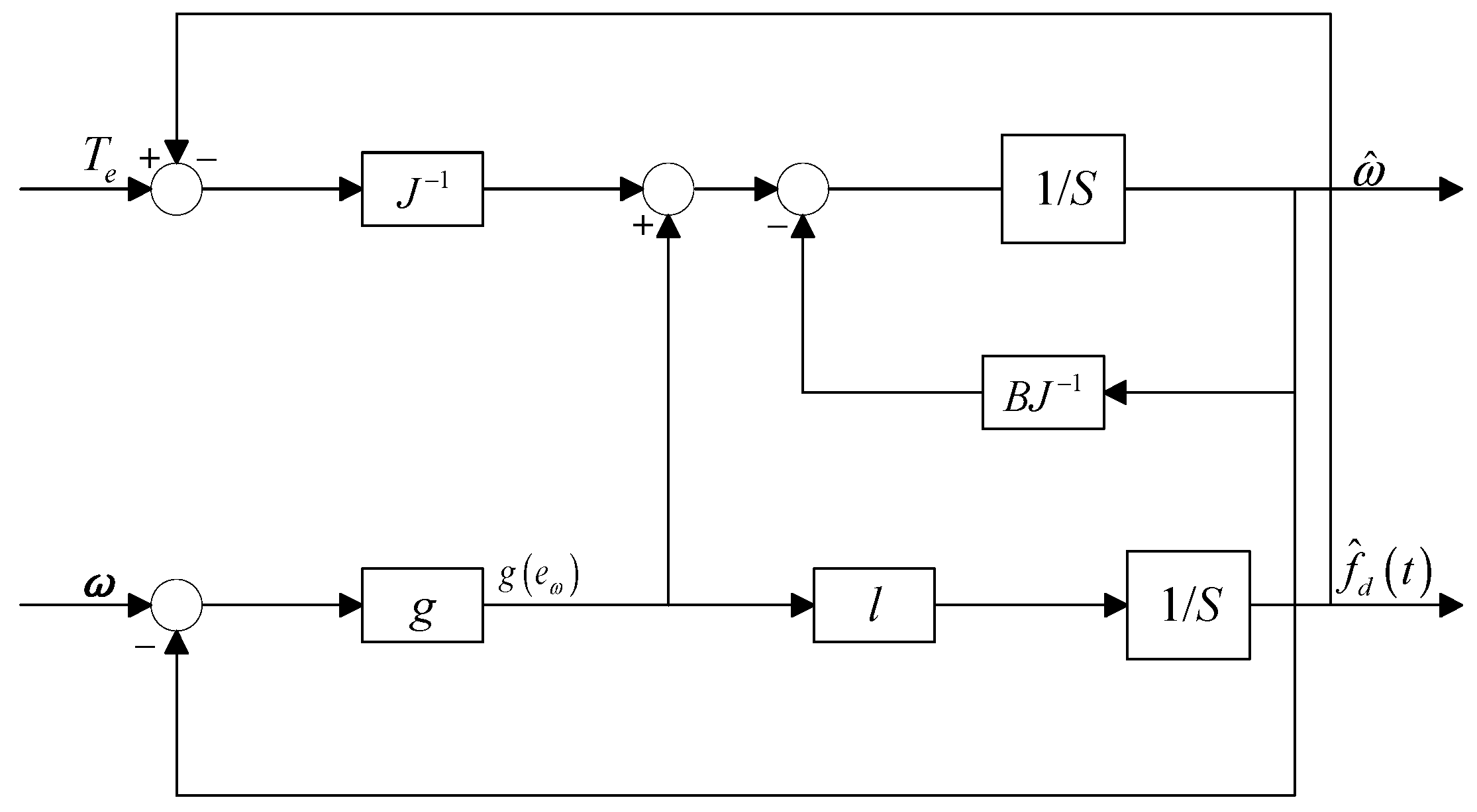
To further enhance the system’s disturbance rejection performance, a sliding-mode disturbance observer (SMDO) was designed. Its structural block diagram is shown in Figure 3.
In the servo motor control system, the load disturbance torque varies slowly relative to other system state signals, and its first derivative can be considered zero:
d T L d t = 0 .
From Equation (51), the first derivative of the disturbance fd(t) is given by:
f ˙ d t = 0 .
By taking the mechanical angular velocity ω and the total disturbance fd(t) as state variables, the electromagnetic torque Te as the system input, and the mechanical angular velocity ω as the system output, the augmented state-space equation can be expressed as:
ω ˙ f ˙ d = B / J 1 / J 0 0 ω f d + 1 / J 0 T e ,
where B denotes the viscous friction coefficient, and J represents the moment of inertia.
Taking the mechanical angular velocity ω and the total disturbance fd(t) as the observed variables, the sliding-mode observer equation can be derived from Equation (53) as:
ω ^ ˙ f ^ ˙ d = B / J 1 / J 0 0 ω ^ f ^ d + 1 / J 0 T e + 1 l g e ω ,
where l is the observer gain, and g(eω) is the sliding-mode control law based on the observation error eω.
From Equations (53) and (54), the error equation of the sliding-mode disturbance observer can be expressed as:
e ˙ ω = B J e ω 1 J e T g e ω e ˙ T = l g e ω ,
where e ω = ω ω ^ denotes the velocity observation error, and e T = f d f ^ d represents the disturbance observation error.
Select the sliding surface s:
s = e ω + c ω 0 t e ω d t .
Differentiating s yields:
s ˙ = e ˙ ω + c ω e ω .
Select the reaching low:
s ˙ = ε sign s ,
where ε is the switching gain.
By combining Equations (55), (57), and (58), treating 1 J e T as the disturbance term, the control law for the sliding-mode disturbance observer can be designed as:
g e ω = c ω B J e ω + ε sign s .
Based on the control law, the system trajectory can reach and remain on the sliding surface within a finite time, yielding:
s = s ˙ = 0 ,
e ω = e ˙ ω .
From Equation (55), we obtain:
e T = J g e ω e ˙ T = l g e ω .
From Equation (62), we obtain:
e T = c T e l J t .
where cT is a constant. To ensure that the disturbance observation error eT converges to zero, the observer gain l must satisfy:
l < 0 .
Define the Lyapunov function:
V = 1 2 s 2 .
Differentiating V yields:
V ˙ = s s ˙ .
By combining Equations (55), (57), and (59), we obtain:
V = s s ˙ = s c e ω B J e ω 1 J e T g e ω = s ε sign s 1 J e T .
According to Lyapunov stability theory, the conditions for the existence and reachability of the sliding surface are:
V ˙ = s s ˙ < 0 .

3.3. Design of the Decoupled Linear Extended State Observer

In LADRC design, the controller bandwidth is generally expected to determine the system’s tracking performance, while the observer gain of the LESO dictates the system’s disturbance rejection capability. However, in conventional LADRC, tracking performance and disturbance rejection are coupled, mutually influencing and constraining each other. The following analyzes the coupling issue between tracking performance and disturbance rejection in LADRC.
Applying the Laplace transform to Equation (44) yields the relationship among the input u, the output y, and the state variables:
z 1 = b 0 s s 3 + β 1 s 2 + β 2 s + β 3 u s + β 1 s 2 + β 2 s + β 3 s 3 + β 1 s 2 + β 2 s + β 3 y s z 2 = b 0 s s + β 1 s 3 + β 1 s 2 + β 2 s + β 3 u s + β 2 s 2 + β 3 s s 3 + β 1 s 2 + β 2 s + β 3 y s z 3 = b 0 β 3 s 3 + β 1 s 2 + β 2 s + β 3 u s + β 3 s 2 s 3 + β 1 s 2 + β 2 s + β 3 y s .
Substituting Equation (69) into Equation (45) yields the expression for u0:
u 0 = k p r b 0 s s 3 + β 1 s 2 + β 2 s + β 3 u s β 1 s 2 + β 2 s + β 3 s 3 + β 1 s 2 + β 2 s + β 3 y s k d b 0 s s + β 1 s 3 + β 1 s 2 + β 2 s + β 3 u s + β 2 s 2 + β 3 s s 3 + β 1 s 2 + β 2 s + β 3 y s .
By substituting Equations (69) and (70) into Equation (45), the relationship among the input r, the output y, and the control variable u is obtained:
u = 1 b 0 × s 3 + β 1 s 2 + β 2 s + β 3 s 3 + k d + β 1 s 2 + k p + k d β 1 + β 2 s × k p r k p β 1 + k d β 2 + β 3 s 2 + k p β 2 + k d β 3 s + k p β 3 s 3 + β 1 s 2 + β 2 s + β 3 y .
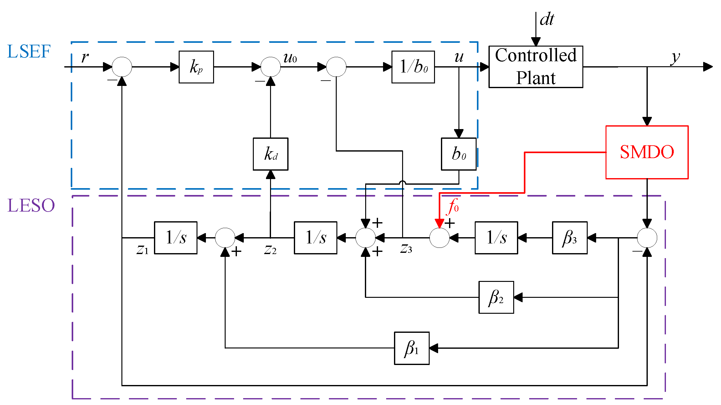
Based on the previously derived sliding-mode disturbance observer, the total disturbance of the system is measured, and the observed disturbance f0 is incorporated as a compensation term into the LESO state equation, so that the LESO only needs to observe the residual disturbance f-f0. This approach not only reduces the observational burden on the LESO but also improves the accuracy of disturbance estimation and enhances closed-loop disturbance rejection. The corresponding control structure is shown in Figure 4. Therefore, the design of the decoupled linear extended state observer is as follows:
e = y z 1 z ˙ 1 = z 2 + β 1 e z ˙ 2 = z 3 + β 2 e + b 0 u + f 0 z ˙ 3 = β 3 e .
The control law is designed as follows:
e 2 = r z 1 u 0 = k p r z 1 k d z 2 u = u 0 z 3 + f 0 / b 0 .
Define the error functions of the three states as ei(s):
e 1 s = Z 1 s y s e 2 s = Z 2 s y s e 3 s = Z 3 s x 3 s = Z 3 s y ¨ s + b 0 u s .
By substituting Equation (69), we obtain:
e 1 s = b 0 s s 3 + β 1 s 2 + β 2 s + β 3 u s s 3 s 3 + β 1 s 2 + β 2 s + β 3 y s e 2 s = b 0 s s 3 + β 1 s 2 + β 2 s + β 3 u s s + β 1 s 3 s 3 + β 1 s 2 + β 2 s + β 3 y s e 3 s = s 3 + β 2 s 2 + β 2 s s 3 + β 1 s 2 + β 2 s + β 3 b 0 u s s 3 + β 2 s 2 + β 2 s s 3 + β 1 s 2 + β 2 s + β 3 s 2 y s .
When y and u are step signals, we have y s = 1 / s ,   u s = 1 / s ; thus, the steady-state error can be expressed as:
e s 1 = lim s 0 s e 1 s = 0 e s 2 = lim s 0 s e 2 s = 0 e s 3 = lim s 0 s e 3 s = 0
The steady-state errors of all three states are zero; therefore, the decoupled linear extended state observer converges, remains stable, and exhibits excellent tracking performance.

4. Simulation and Experimentation

4.1. Servo Motor Simulation Experiment

The control objective of this study is to enable the moving platform center of the shipborne 3RRS-RUS parallel stabilization platform to accurately track a given pose trajectory under load, thereby ultimately maintaining the platform stationary relative to the inertial frame. To achieve this, a three-loop servo motor control strategy is proposed. The required driving link angles are calculated via inverse kinematics based on the commanded position and orientation of the moving platform. The controller architecture is shown in Figure 5. Specifically, the position loop employs an LADRC controller combined with a sliding-mode disturbance observer, the velocity loop uses a sliding-mode controller, and the current loop is governed by a PID controller. The PID current loop enables rapid dynamic response of the current, the sliding-mode velocity loop ensures stable speed regulation, and the LADRC position loop together with the sliding-mode disturbance observer estimates and compensates the total disturbance to quickly reach the desired position. The disturbance observer also alleviates the observational load on the LESO, enhancing disturbance estimation performance. LADRC features a simple structure, model-independent disturbance estimation, and strong adaptability to parameter variations, making it particularly suitable for real-time control of nonlinear and uncertain shipborne systems. The overall three-loop control structure is illustrated in Figure 6.
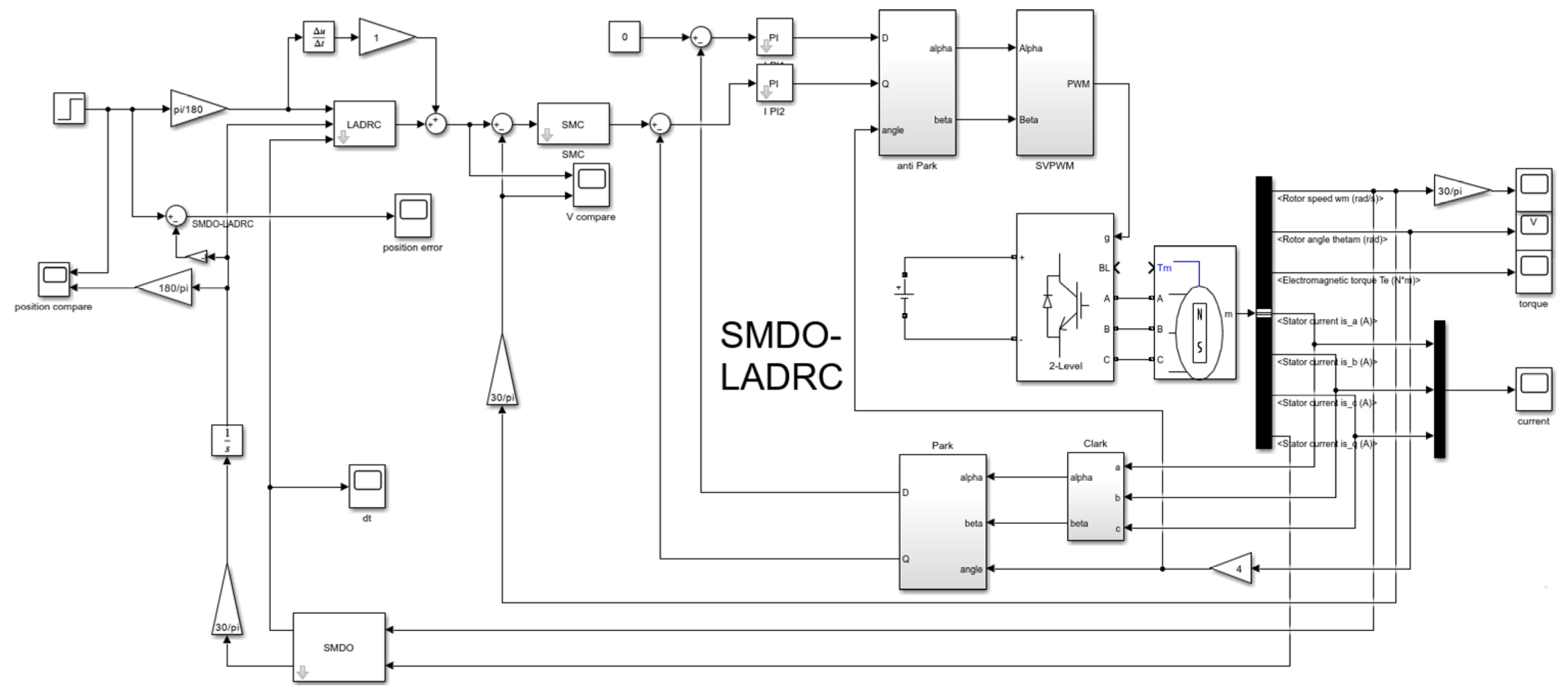
To validate the performance of the proposed SMDO–LADRC controller, a simulation model was developed in MATLAB/Simulink R2023b, as shown in Figure 7. The motor parameters were set as follows: rotor angle of 60°, 4 pole pairs, rated speed of 3000 r/min, rated torque of 0.64 N·m, rated current of 1.3 A, rated power of 0.2 kW, and a motor weight of 0.78 kg. The simulation was run for 0.1 s.
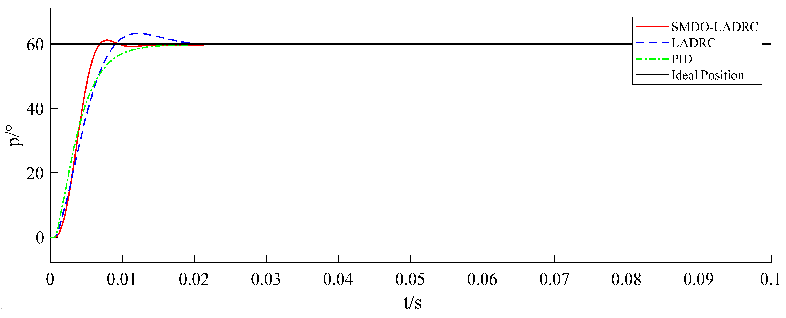
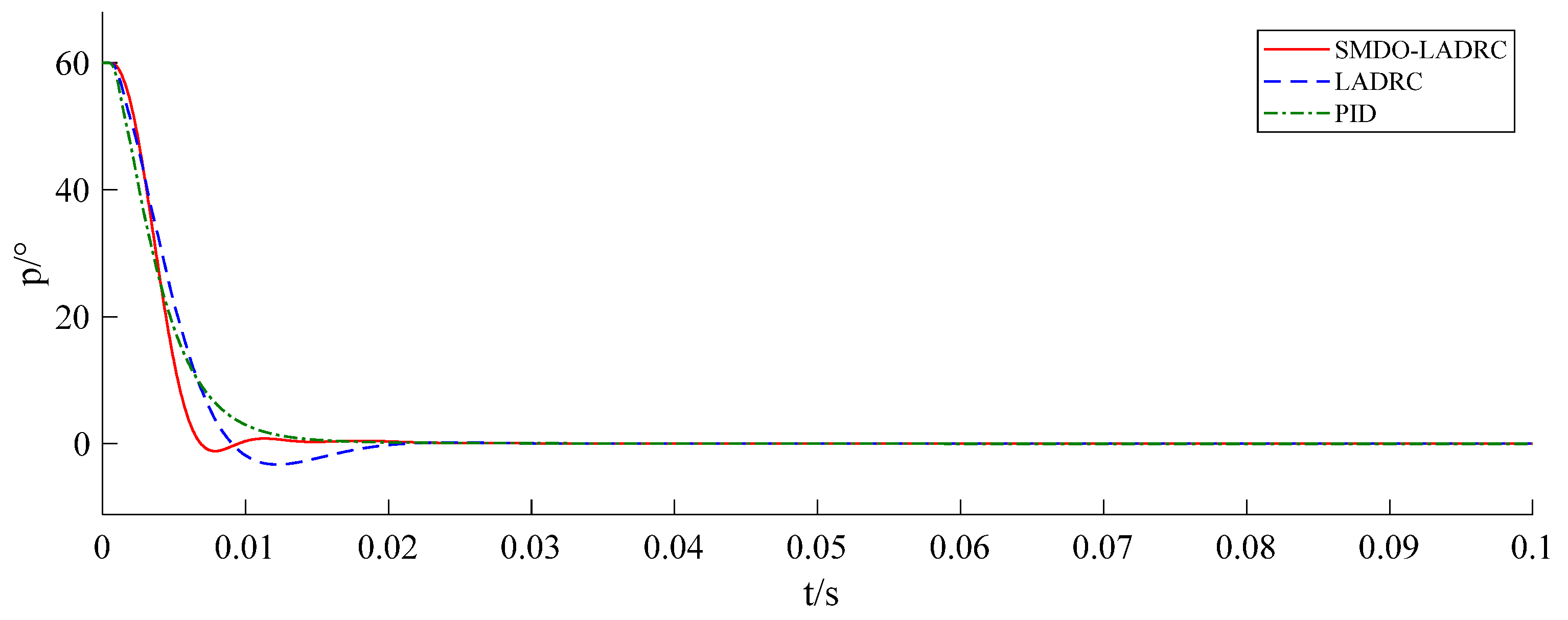
Figure 8 and Figure 9 show the comparative experiments of the position loop control using SMDO–LADRC, LADRC, and PID. As can be seen from Figure 8, the SMDO–LADRC exhibits faster response, stronger regulation capability, and smaller overshoot compared with LADRC. Figure 9 presents the position control error comparison, indicating that the average error of SMDO–LADRC is reduced by approximately 5% compared with LADRC and by 10% compared with PID. The quantitative performance indices of the step responses are summarized in Table 2.

4.2. Motor Hardware-in-the-Loop Simulation Based on CSPACE

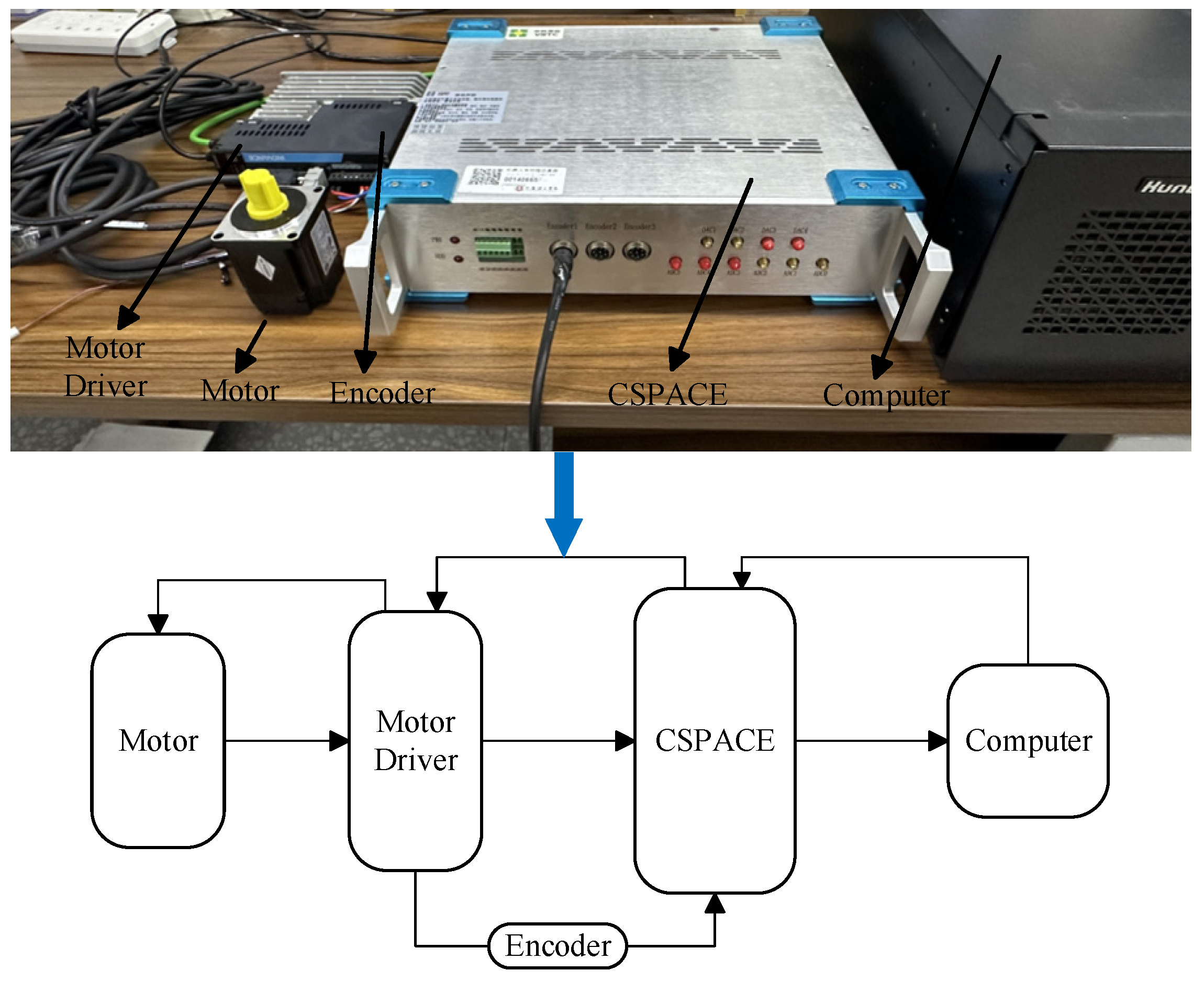
This study employs the CSPACE experimental platform to conduct hardware-in-the-loop simulation for a single motor. The experimental setup is shown in Figure 10 and includes a servo motor, driver, built-in encoder, CSPACE-V3 (VSTC, Hefei, China), and a computer. The servo motor used is the Inovance MS1H4-20B30CB-A331R (INOVANCE, Shenzhen, China), and the driver is the Inovance SV660CS1R6I (INOVANCE, Shenzhen, China), with a TMS320F28335 as the main control chip. CSPACE integrates computer simulation with embedded real-time control, supporting both Hardware-in-the-Loop (HIL) and Rapid Control Prototyping (RCP) functionalities. Using RCP, control algorithms can be simulated in MATLAB/Simulink, with input and output interfaces mapped to the CSPACE module. After compiling and automatically generating DSP code, the system can run directly on CSPACE, enabling convenient control of the target device. For HIL applications, the system runs a Simulink model of the controlled object to simulate its behavior. Control inputs are received via the input interface, while the system state is output through the output interface. This setup allows testing of the actual controller and implements true hardware-in-the-loop simulation.
In this experiment, the driver communicates with the CSPACE via the CAN protocol, while the CSPACE interfaces with the computer through a serial connection. A real-time simulation system is built in Simulink, where commands are sent to the driver via CAN, and position feedback from the encoder is received by the CSPACE, as illustrated in Figure 11.
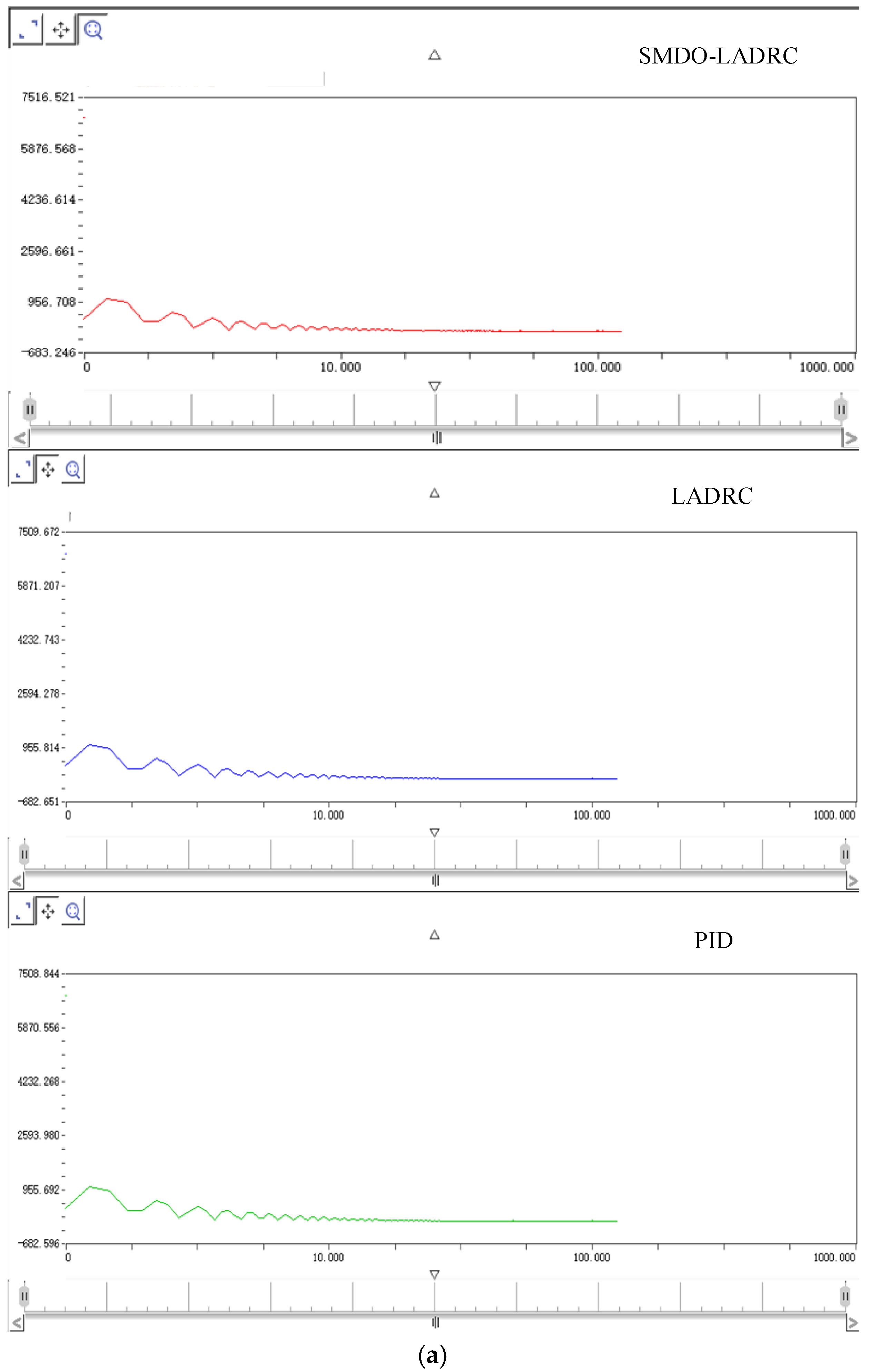
The motor has a rated speed of 3000 r/min, a rated torque of 0.64 N·m, a rated current of 1.3 A, a rated power of 0.2 kW, and a weight of 0.78 kg. The motor position signal is set to 9330 p. The corresponding experimental results are shown in Figure 12.
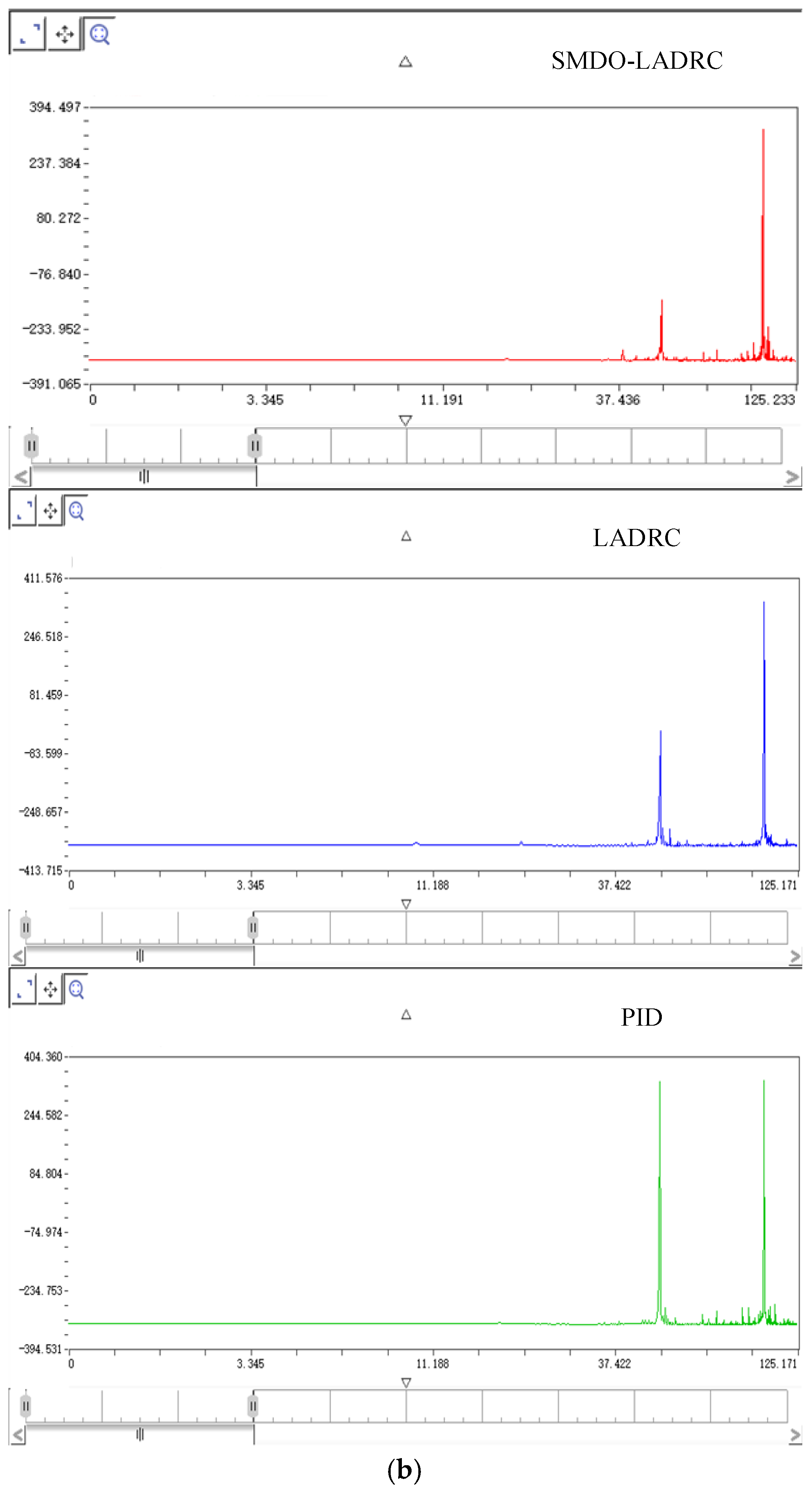
Figure 13a presents the Fourier transform amplitude curves for the three control methods. The analysis shows that at low frequencies, when the servo motor starts, the dynamic error is relatively large, while at high frequencies, the dynamic error approaches zero. Overall, the curves decay smoothly, indicating sufficient bandwidth and stable control. Figure 13b depicts the Bode plots for the three methods. It is evident that SMDO–LADRC exhibits the lowest amplitude, followed by LADRC, and then PID. At the first peak, the amplitudes are 71.775 for SMDO–LADRC, 98.711 for LADRC, and 208.566 for PID. Compared with LADRC, SMDO–LADRC reduces the amplitude by 27.308%, and compared with PID, the reduction is 65.596%. At the second peak, the amplitudes of all three methods are nearly identical.
The primary purpose of this single-channel HIL test is to verify the feasibility and real-time control performance of the proposed LADRC + SMDO scheme under realistic servo conditions. In future work, a multi-actuator HIL configuration will be developed to further analyze the dynamic interactions among actuators and provide a more comprehensive system-level validation.

4.3. SimMechanics-Based Simulation Experiment of the 3RRS-RUS Shipborne Parallel Stabilization Platform

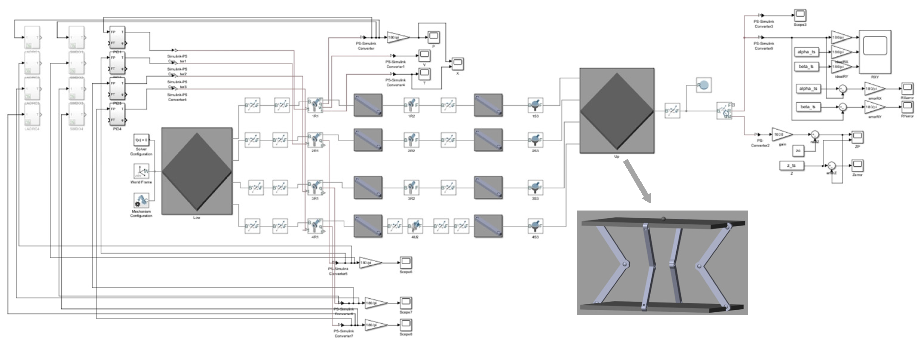
A 3RRS-RUS shipborne parallel stabilization platform model was built in SimMechanics, as shown in Figure 14. The platform consists of a moving platform, a fixed platform, three RRS branches, and one RUS. The fixed platform is anchored to the ground, with revolute joints (R) located at the centers of its four sides. For branches 1–3, both ends of the driving links are connected to revolute joints. For the fourth, redundant branch, one end of the driving link is connected to a revolute joint on the fixed platform, while the other end is connected via a universal joint (U). The four driven links are connected to the centers of the moving platform edges via spherical joints (S).
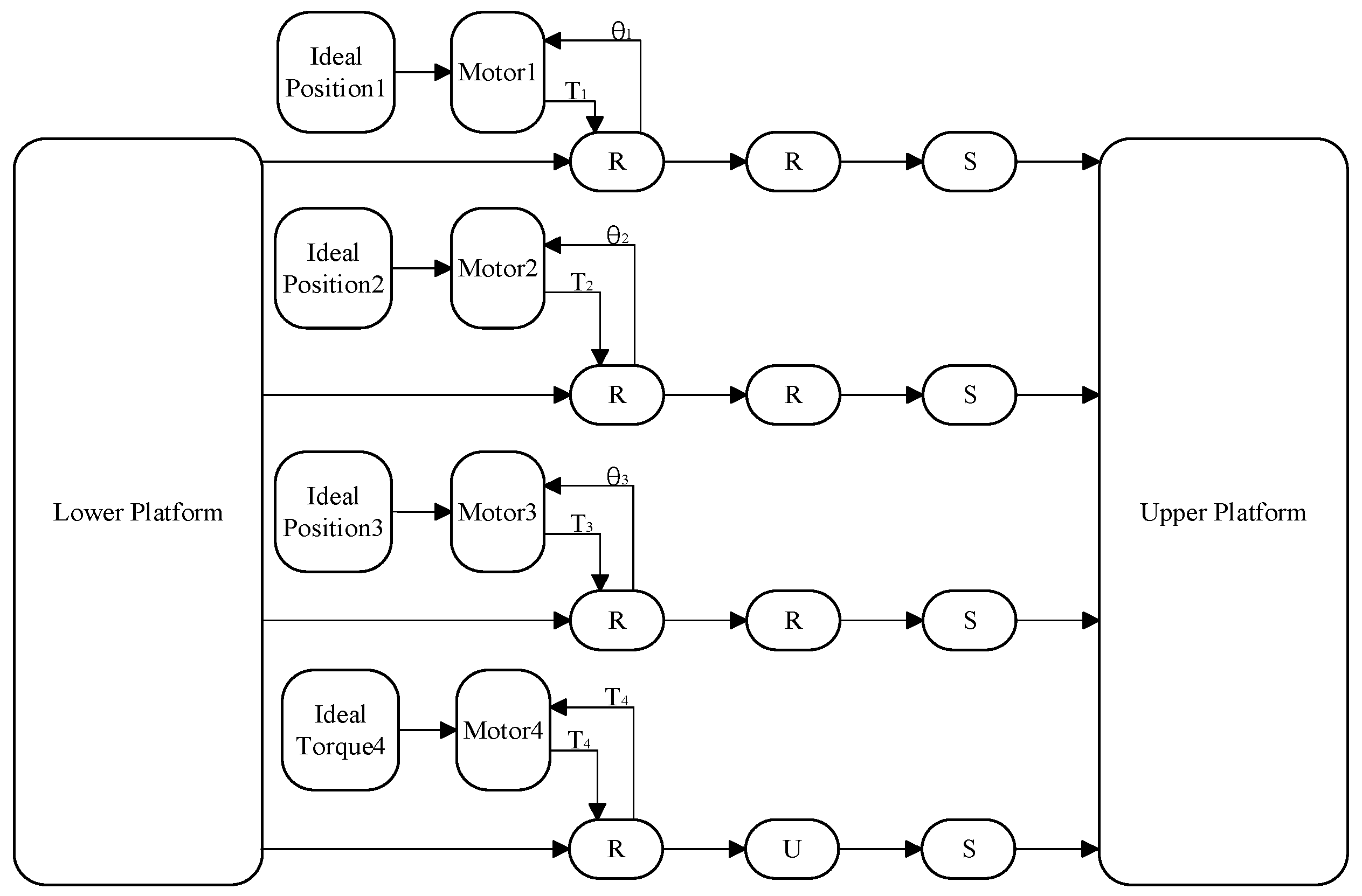
The servo motors are connected to the driving rods and the revolute joints on the fixed platform. By specifying the pose of the moving platform’s center, the inverse kinematics are used to calculate the driving angles for the three RRS branches. These angles are fed to the motors’ position loops, so that the motors output torque to the revolute joints, which in turn provide angle feedback back to the motors. For the RUS, a specified motor torque is applied; the motor delivers torque to the revolute joint, which then feeds torque back to the motor. In this way, a complete closed-loop control system is established. The control structure is illustrated in Figure 15.
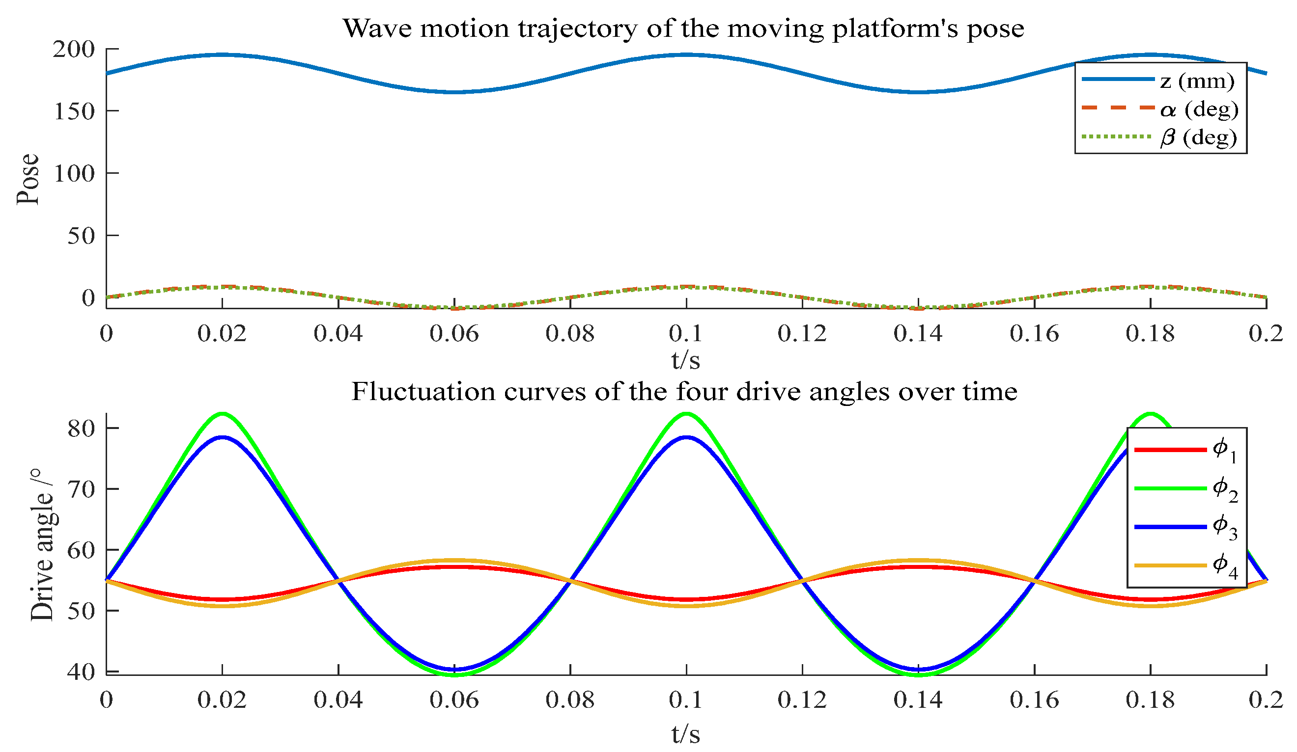
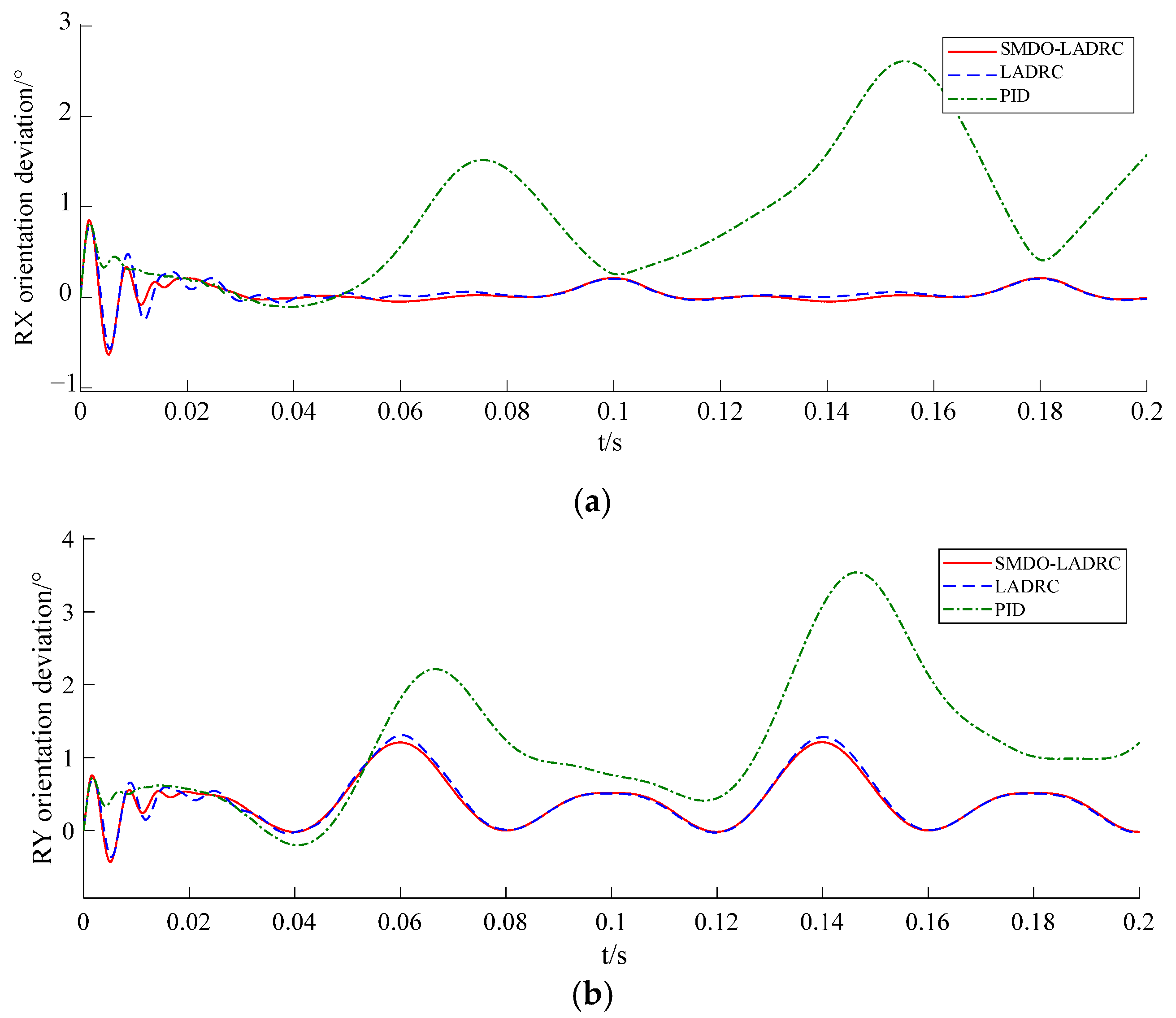
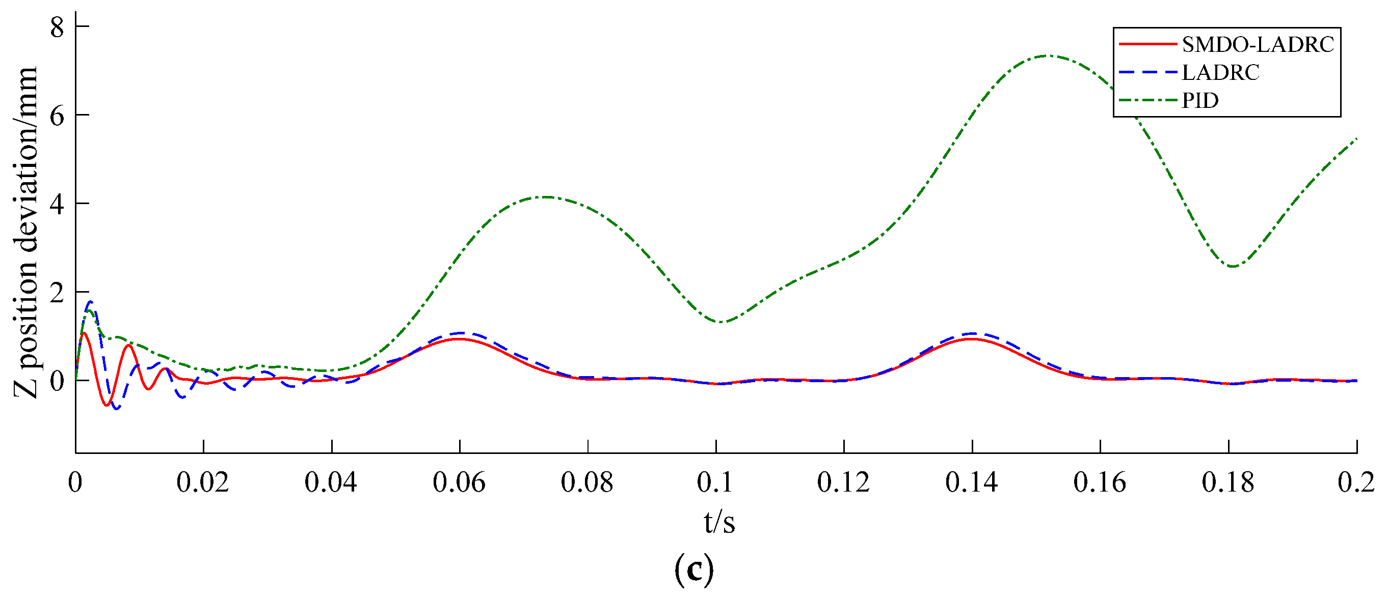
The initial angles of the revolute joints were set to 55°, with the side lengths of both the moving and fixed platforms at 300 mm. The lengths of the driving and driven rods were both 110 mm. The moving platform carried a load of 100 N. The commanded motion of the moving platform followed a wave pattern: ±15 mm translation along the Z-axis, ±9° rotation about the X-axis, and ±8° rotation about the Y-axis. The reference trajectory is shown in Figure 16. Due to space limitations, only the single-motor error is presented, specifically the position error of the actuator on the third RRS branch, as illustrated in Figure 17. The moving platform’s tracking errors—rotation about the X-axis, rotation about the Y-axis, and translation along the Z-axis—are shown in Figure 18.
As shown in Figure 17, the proposed SMDO–LADRC exhibits fast response, minimal overshoot, and strong tracking performance, demonstrating superior disturbance rejection compared with LADRC. In Figure 18, Under wave disturbance, due to the lack of robustness against external interferences, the PID controller fails to accurately track the desired angle during long-term simulations, and the tracking error gradually increases.
In contrast, the proposed Improved LADRC exhibits strong stability and effective disturbance-rejection capability, maintaining convergence and smooth tracking under the same operating conditions. The average position errors are 0.083524° for SMDO–LADRC, 0.103256° for LADRC, and 2.407492° for PID. Compared with LADRC, SMDO–LADRC reduces the average error by 19.1%, and compared with PID, by 96.5%. Figure 18 illustrates that SMDO–LADRC achieves excellent tracking performance across all three degrees of freedom of the 3RRS-RUS parallel stabilization platform, with strong disturbance rejection. Specifically, about the RX axis, SMDO–LADRC reduces the average error by 6.5% compared with LADRC and 91.6% compared with PID; about the RY axis, the reductions are 1.1% and 64.7%, respectively; and along the Z axis, the reductions are 16.6% and 92.8%, respectively.
Although the proposed 3RRS–RUS stabilization platform focuses on compensating for roll, pitch, and heave, the remaining ship motions—yaw, surge, and sway—can still influence overall stability, especially under large-amplitude sea waves. These motions may introduce coupling effects that slightly affect the attitude precision of the moving platform. In future work, we will evaluate the influence of other ship motion degrees of freedom on the stability of the mechanism and consider methods to compensate for the disturbances caused by these remaining degrees of freedom. Such an extension would further enhance the platform’s adaptability and performance under complex marine operating conditions.

5. Conclusions

A novel redundantly actuated three-DOF shipborne parallel stabilization platform without parasitic motion, namely the 3RRS-RUS mechanism, is designed in this work. An SMDO–LADRC-based triple-loop motor control strategy is proposed. By decoupling the conventional LADRC, a new linear state observer and control law are developed, while a sliding-mode disturbance observer is incorporated into the motor’s triple-loop structure to alleviate the estimation burden of the linear extended state observer and enhance disturbance rejection capability. In the CSPACE experiments, comparative tests with three control methods demonstrate that all approaches ensure stable operation, with the proposed SMDO–LADRC achieving higher control accuracy. Furthermore, a 3RRS-RUS parallel stabilization platform simulation model is constructed in SimMechanics. By applying inverse kinematics to compute the drive angles from the prescribed platform poses, simulations are performed. The results confirm that the proposed SMDO–LADRC exhibits superior tracking performance, strong robustness, and excellent disturbance rejection. In the 2R1T degrees of freedom (RX, RY, Z), the tracking errors are reduced by 6.5%, 1.1%, and 16.6%, respectively, compared with conventional LADRC, thereby verifying the effectiveness of the proposed 3-DOF 3RRS-RUS shipborne parallel stabilization platform.

Author Contributions

Conceptualization, Y.W.; methodology, Y.W. and H.Q.; software, Y.W.; validation, Y.W., H.Q., S.K., K.L. and X.T.; formal analysis, Y.W. and J.Y.; investigation, Y.W., H.Q., S.K. and K.L.; resources, S.K.; data curation, H.Q., J.Y. and H.W.; writing—original draft preparation, Y.W.; writing—review and editing, Y.W.; visualization, Y.W., S.K., K.L. and X.T.; supervision, J.Y. and H.W.; project administration, H.Q.; funding acquisition, Y.W., H.Q., S.K. and K.L. All authors have read and agreed to the published version of the manuscript.

Funding

This research was funded by the Natural Science Foundation of the Jiangsu Higher Education Institutions of China, grant number 23KJA460006 and Postgraduate Research & Practice Innovation Program of Jiangsu Province, grant number XSJCX24_48.

Data Availability Statement

Where no new data were created, or where data is unavailable due to privacy or ethical restrictions.

Conflicts of Interest

The authors declare no conflicts of interest. The funders had no role in the design of the study; in the collection, analyses, or interpretation of data; in the writing of the manuscript; or in the decision to publish the results.

Abbreviations

The following abbreviations are used in this manuscript:
ADRCActive Disturbance Rejection Control
SMDOSliding-Mode Disturbance Observer
ESOExtended State Observer
MPCModel Predictive Control
DOFDegree of Freedom
RRSRevolute–Revolute–Spherical joint
HILHardware-in-the-Loop
RCPRapid Control Prototyping

References

  1. Monsarrat, B.; Gosselin, C.M. Workspace analysis and optimal design of a 3-leg 6-DOF parallel platform mechanism. IEEE Trans. Robot. Autom. 2003, 19, 954–966. [Google Scholar] [CrossRef]
  2. Kim, S.H.; Jeon, D.; Shin, H.P.; In, W.; Kim, J. Design and analysis of decoupled parallel mechanism with redundant actuator. Int. J. Precis. Eng. Manuf. 2009, 10, 93–99. [Google Scholar] [CrossRef]
  3. Wang, L.; Xu, H.; Guan, L. Optimal design of a 3-PUU parallel mechanism with 2R1T DOFs. Mech. Mach. Theory 2017, 114, 190–203. [Google Scholar] [CrossRef]
  4. Li, Y.; Zheng, H.; Chen, B.; Sun, P.; Wang, Z.; Shuai, K.; Yue, Y. Dynamic Modeling and Analysis of 5-PSS/UPU Parallel Mechanism with Elastically Active Branched Chains. Chin. J. Mech. Eng. 2020, 33, 44. [Google Scholar] [CrossRef]
  5. Du, X.; Li, Y.; Wang, P.; Ma, Z.; Li, D.; Wu, C. Design and optimization of solar tracker with U-PRU-PUS parallel mechanism. Mech. Mach. Theory 2021, 155, 104107. [Google Scholar] [CrossRef]
  6. Tang, G.; Lei, J.; Li, F.; Zhu, W.; Xu, X.; Yao, B.; Claramunt, C.; Hu, X. A modified 6-DOF hybrid serial–parallel platform for ship wave compensation. Ocean Eng. 2023, 280, 114336. [Google Scholar] [CrossRef]
  7. Guo, L.-D.; Tan, Z.-F. Application of a sliding mode variable structure controller for stabilized platform of shipborne weapons. In Proceedings of the 2010 2nd IEEE International Conference on Information Management and Engineering, Chengdu, China, 16–18 April 2010; pp. 65–68. [Google Scholar] [CrossRef]
  8. Qiang, S.; Jin, X.; Feng, D.H.; Xue, L.; Zhang, L. Model Predictive Control of a Shipborne Hydraulic Parallel Stabilized Platform Based on Ship Motion Prediction. IEEE Access 2020, 8, 181880–181892. [Google Scholar] [CrossRef]
  9. Cai, Y.; Zheng, S.; Liu, W.; Qu, Z.; Zhu, J.; Han, J. Sliding-mode control of ship-mounted Stewart platforms for wave compensation using velocity feedforward. Ocean Eng. 2021, 236, 109477. [Google Scholar] [CrossRef]
  10. Chen, W.; Wang, S.; Li, J.; Lin, C.; Yang, Y.; Ren, A.; Li, W.; Zhao, X.; Zhang, W.; Guo, W.; et al. An ADRC-based triple-loop control strategy of ship-mounted Stewart platform for six-DOF wave compensation. Mech. Mach. Theory 2023, 184, 105289. [Google Scholar] [CrossRef]
  11. Chen, W.; Wen, Y.; Tong, X.; Lin, C.; Li, J.; Wang, S.; Xie, W.; Mao, L.; Zhao, X.; Zhang, W.; et al. Dynamics Modeling and Modal Space Control Strategy of Ship-Borne Stewart Platform for Wave Compensation. J. Mech. Robot. 2023, 15, 041015. [Google Scholar] [CrossRef]
  12. Wen, Y.; Li, W.; Zhou, S.; Gao, F.; Chen, W. Robust sliding mode control with adaptive gravity estimation of ship-borne Stewart platform for wave compensation. Appl. Ocean Res. 2024, 148, 104004. [Google Scholar] [CrossRef]
  13. Tu, Y.; Du, J.; Li, J. PTESO based robust stabilization control and its application to 3-DOF ship-borne parallel platform. Ocean Eng. 2023, 284, 115202. [Google Scholar] [CrossRef]
  14. Li, D.; Wang, S.; Song, X.; Zheng, Z.; Tao, W.; Che, J. A BP-Neural-Network-Based PID Control Algorithm of Shipborne Stewart Platform for Wave Compensation. J. Mar. Sci. Eng. 2024, 12, 2160. [Google Scholar] [CrossRef]
  15. Liu, X.; Shao, M.; Zhang, T.; Zhou, H.; Song, L.; Jia, F.; Sun, C.; Yang, Z. Research on Motion Control and Compensation of UAV Shipborne Autonomous Landing Platform. World Electr. Veh. J. 2024, 15, 388. [Google Scholar] [CrossRef]
  16. Chen, W.; Lin, C.; Zhou, S.; Zhao, X.; Li, D.; Wu, E.Q.; Zhu, L. Dynamic Modeling and Robust Inverse Dynamics Control Enhanced by Optimal Equivalent Input Disturbance for a Shipborne Wave Compensation Hexapod Platform. IEEE/ASME Trans. Mechatron. [CrossRef]
  17. Qiang, S.; Wang, Y.H.; Wang, R.; Liu, K.; Kang, S.; Yang, J. Model Predictive Control Considering Load Disturbance of Ship-Borne Hydraulic Parallel Platform. IEEE Access 2024, 12, 197201–197216. [Google Scholar] [CrossRef]
  18. Chen, X.; Zeng, H.; Gu, Q.; Chen, Z.; Meng, Z.; Zhang, L. Dual-layer adaptive predictive control for wave compensation of electro-hydraulic Stewart platforms. Ocean Eng. 2025, 340, 122293. [Google Scholar] [CrossRef]
  19. Shi, X.; Chang, S.; Huang, J. Motion control of a novel 6-degree-of-freedom parallel platform based on modified active disturbance rejection controller. Proc. Inst. Mech. Eng. Part I J. Syst. Control Eng. 2013, 228, 87–96. [Google Scholar] [CrossRef]
  20. Xie, D.; Yao, X.; Zhang, D.; Ye, B. Stability control of ship-borne photoelectric tracking servo system based on LADRC. In Proceedings of the 2016 35th Chinese Control Conference (CCC), Chengdu, China, 27–29 July 2016; pp. 5920–5924. [Google Scholar] [CrossRef]
  21. Zhang, D.; Wu, Q.; Yao, X.; Xie, D.; Jiao, L. Design and implementation of active disturbance rejection control for the ship-borne photoelectric tracking servo system. In Proceedings of the 2017 29th Chinese Control And Decision Conference (CCDC), Chongqing, China, 28–30 May 2017; pp. 3951–3956. [Google Scholar] [CrossRef]
  22. Yang, X.; Huang, Q.; Jing, S.; Zhang, M.; Zuo, Z.; Wang, S. Servo system control of satcom on the move based on improved ADRC controller. Energy Rep. 2022, 8, 1062–1070. [Google Scholar] [CrossRef]
  23. Jia, T.; Li, M. Design of variable gain auto disturbance rejection controller for photoelectric stabilization platform. In International Symposium on Artificial Intelligence Control and Application Technology (AICAT 2022); SPIE: Bellingham, WA, USA, 2022; Volume 12305, pp. 159–165. [Google Scholar]
Figure 1. Schematic diagram of the 3RRS-RUS parallel mechanism.
Actuators 14 00564 g001
Figure 2. Basic Structure of LADRC.
Actuators 14 00564 g002
Figure 3. Structural Block Diagram of the Sliding-Mode Disturbance Observer.
Actuators 14 00564 g003
Figure 4. LADRC structure diagram.
Actuators 14 00564 g004
Figure 5. Control strategy for the 3RRS-RUS shipborne parallel stabilization platform.
Actuators 14 00564 g005
Figure 6. Three-loop control structure diagram.
Actuators 14 00564 g006
Figure 7. Motor simulation model.
Actuators 14 00564 g007
Figure 8. Position control simulation comparison.
Actuators 14 00564 g008
Figure 9. Position control error comparison.
Actuators 14 00564 g009
Figure 10. CSPACE experimental platform.
Actuators 14 00564 g010
Figure 11. CSPACE real-time simulation system.
Actuators 14 00564 g011
Figure 12. Position control curve. (a) SMDO–LADRC position control curve. (b) LADRC position control curve. (c) PID position Control Curve.
Actuators 14 00564 g012
Figure 13. Fourier Transform and Bode Plot Amplitude Curves. (a) Fourier Transform Amplitude Curve. (b) Bode Plot Amplitude Curve.
Actuators 14 00564 g013aActuators 14 00564 g013b
Figure 14. 3RRS-RUS SimMechanics Simulation Model.
Actuators 14 00564 g014
Figure 15. 3RRS-RUS SimMechanics Control Structure Diagram.
Actuators 14 00564 g015
Figure 16. Reference trajectory of the 3RRS-RUS moving platform.
Actuators 14 00564 g016
Figure 17. Position error of the third RRS branch drive motor.
Actuators 14 00564 g017
Figure 18. 3-DOF position deviation. (a) RX orientation deviation. (b) RY orientation deviation. (c) Z orientation deviation.
Actuators 14 00564 g018aActuators 14 00564 g018b
Table 1. Comparison between the Stewart platform and the proposed 3RRS–RUS stabilization mechanism.
ItemStewart Platform3RRS-RUS
Degrees of freedom6-DOF3-DOF
Joint composition6 UPS legs 3 RRS legs +1 RUS leg
Number of passive jointsHighLower
Structural complexityHighLower
ManufacturabilityHarder to assemble and calibrateEasier to fabricate and assemble
Control difficulty6-DOF control3-DOF control
Dynamic performanceHeavy structure and larger inertiaSmaller inertia improves response speed
Table 2. Step response performance comparison under different controllers.
ControllerRise Time (s)Steeling Time (s)Overshoot (%)
PID0.00870.01560.58
LADRC0.00580.00965.50
SMDO–LADRC0.00380.00651.45
Disclaimer/Publisher’s Note: The statements, opinions and data contained in all publications are solely those of the individual author(s) and contributor(s) and not of MDPI and/or the editor(s). MDPI and/or the editor(s) disclaim responsibility for any injury to people or property resulting from any ideas, methods, instructions or products referred to in the content.