1. Introduction
Against the backdrop of global energy transition, oil and gas resources, as critical transitional energy sources, increasingly rely on the development of more technically complex marine oil and gas resources for stable supply. As the core facility for deep-sea oil and gas development, underwater production systems are responsible for the key tasks of oil and gas collection, processing, and transportation. The integrity, safety, and operational efficiency of this system highly depend on the performance of underwater electrical connectors [
1,
2,
3].
In the 1930s, electrical connectors had not yet formed an industrialized process. Typically, rubber materials were wrapped around the connection points of sockets and plugs, and ropes were used to tightly bind them, achieving the sealing of the connector [
4]. After the end of World War II, with the rapid development of naval military power, the demand for underwater electrical connectors surged due to the rapid development of submarines and warships. However, at that time, the connectors had rigid shells, and manual sealing was performed after mating, meaning these connectors could not be mated and demated underwater, and thus were called subsea dry-mateable connectors [
5]. Around 1962, subsea wet-mateable connectors were introduced, the first of which was the PBOF connector, which used sealing chambers and seals to isolate conductive materials from seawater, thus enriching the usage scenarios of subsea wet-mateable connectors. In the 1970s, inductive coupling connectors began to develop [
6]. By the 1990s, underwater hybrid optical and electrical connectors emerged, combining the advantages of all previous connectors [
7].
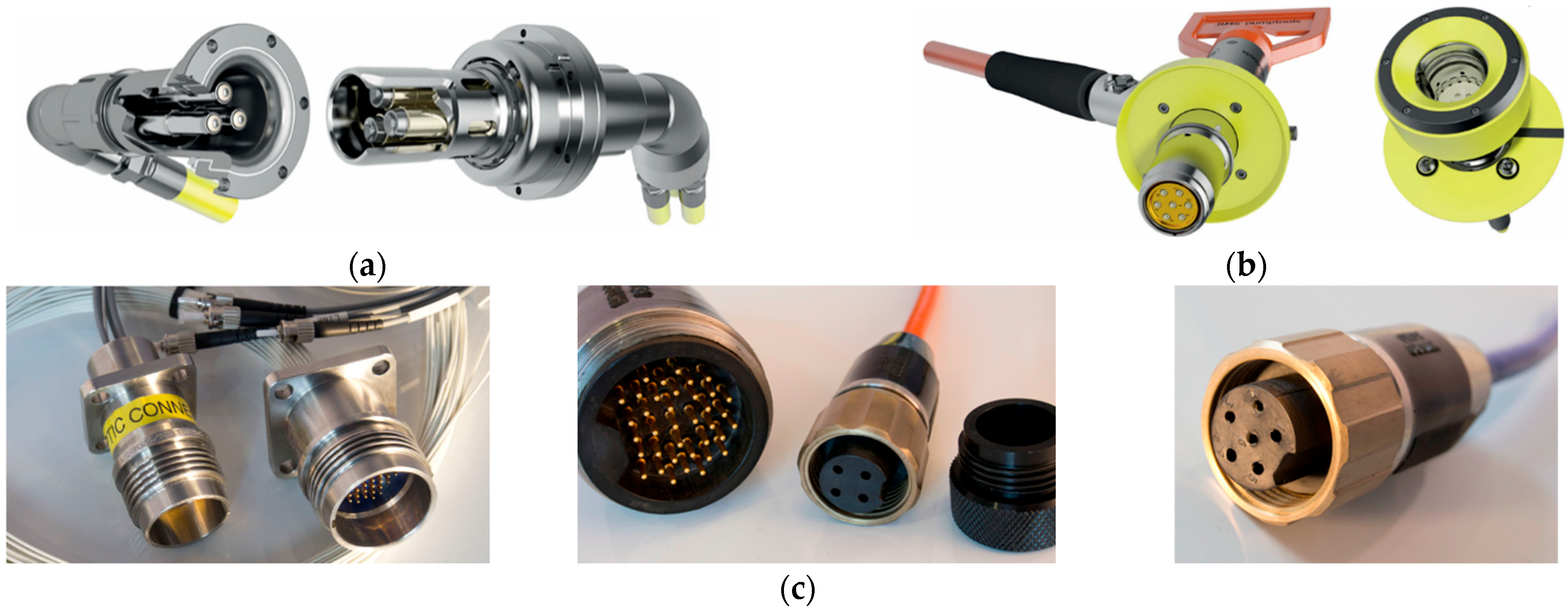
The subsea wet-mateable connectors market is primarily dominated by the United States, Germany, the United Kingdom, and France. The HV wet-mateable connectors produced by the company RMSpumptools, located in Aberdeen, UK, feature a double-seal barrier, allowing the plug connector to be energized without being mated. The operating temperature range extends from −20 °C to 45 °C. Their ROV Wet-Mateable connectors feature seawater-protected contacts for both plugs and sockets, and use the latest oil-filled pressure balancing design, as shown in
Figure 1. The HPS series wet-mateable connectors produced by the company Hydro Group, located in Waterford, CT, USA, adopt a multi-stage redundant sealing design, supporting a mixed configuration of electrical, fiber optic, signal, and hydraulic channels to meet the needs of complex systems. These connectors are made from titanium alloy and Hastelloy materials combined with ceramic insulators, withstanding high deep-sea pressures (>30 MPa) and chemical corrosion, as shown in
Figure 1.
Cairns [
8] conducted a quantitative comparative analysis of the performance characteristics of three typical sealing structures: lip seals, narrow-gap seals, and linear pin-type seals. He proposed a topologically optimized gradient narrow-gap seal configuration, which effectively addresses the interface leakage issue in traditional narrow-gap seals under high dynamic loads. Beurthey’s [
9] research team, addressing the coupling requirements of electrical connectors in deep-sea high-pressure environments, proposed a cost-effective adapter module design based on a simplified architecture. By integrating dynamic pressure compensation mechanisms and optimizing load-bearing structures, they achieved low-cost mating and unmating assistance for deep-sea operations. However, the robustness indicator under multi-physical field coupling conditions only met 62.3% of the ISO13628-6 [
10] standard requirements, highlighting a technological gap in adaptability and reliability under complex operating conditions. Larkin’s [
11] team developed an improved lip seal structure based on a dynamic adjustment mechanism, effectively solving the technical bottleneck of leakage or mechanical jamming in traditional diaphragm sealing components under cyclic pressure conditions. Zhao Q [
12] and others proposed an underwater wet-mate connector based on a multi-lobe elastomer structure, which integrates multi-lobe coupling seals and adaptive locking technology, effectively solving the dual technical bottleneck of sealing failure and mechanical instability in traditional connectors under deep-sea dynamic environments. Song W [
13] and colleagues designed a pressure-resistant wet-mate high-power plug that meets the rapid mating requirements between underwater production trees and riser modules. This design supports a modular maintenance mode that does not require complete disassembly, effectively improving the operational efficiency of oil and gas fields.
He, H. [
14] employed the orthogonal experimental design method to investigate the influence patterns of interference fit and friction coefficient on the insertion force, thereby determining the optimal insertion force for the dynamic sealing process. This research provides a theoretical foundation for the design of deep-sea electrical signal connectors. Zhao, H. [
15] systematically simulated various parameters including friction coefficients, static/dynamic sealing conditions, and compression levels to thoroughly investigate their influence patterns on the contact stress distribution in the sealing area. Quantitative evaluation of the sealing performance was conducted using both the empirical formula method and the Reynolds equation analysis method, with corresponding leakage rate indicators calculated. The study clearly demonstrates that the contact stress under instantaneous dynamic sealing conditions is significantly higher than that under static sealing conditions. Using the finite element method, Zhou, W. [
16] comprehensively analyzes the sealing behaviour of the connector. The results indicate that the contact stress between the sealing elements is primarily governed by radial compression in the sealing region; increasing compression elevates the contact stress, whereas increases in the friction coefficient have only a minor effect. The insertion/extraction speed has no impact on the sealing performance. Li, Y. [
17] investigates the effects of tilt angle, rotation speed, pressure difference, and internal clearance on leakage performance, rotordynamic coefficients, and sealing stability, and proposes a semi-Y labyrinth seal (SYLS) to reduce leakage and enhance the stability of centrifugal pumps.
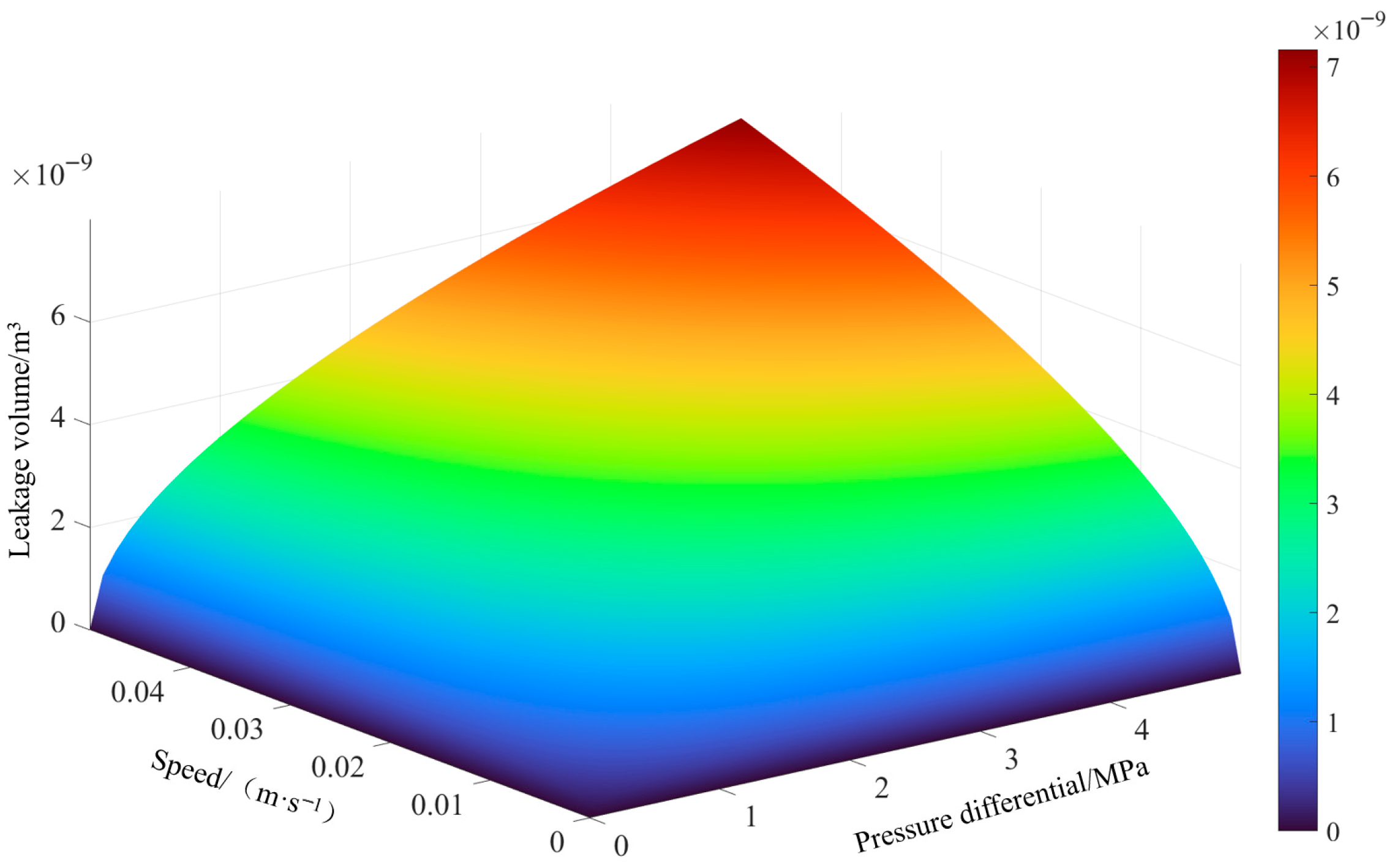
Targeting operations at a water depth of 1500 m, this paper presents a novel underwater wet-mateable connector. The cooperative sealing configuration between the annular protrusion of the entry casing and the sliding sleeve has been optimized, leading to the development of an integrated coupling design that combines pressure balancing with dynamic sealing. An evaluation framework has been established to correlate pressure differential and insertion speed with the leakage volume per insertion–withdrawal cycle. Quantitative analysis of the contact region in the entry casing investigates the influence of protrusion geometry, insertion and withdrawal speeds, coefficient of friction, and radial compression on equivalent stress, deformation, contact pressure, and frictional stress. Based on these analyses, implementable optimal parameters have been identified. Hydrostatic pressure tests performed on the prototype, supplemented by insulation resistance measurements, validate its normal operational performance and sealing reliability under simulated deep-sea conditions.
2. Sealing Mechanism of the Seal
Static sealing in subsea wet-mateable connectors is applied to static contact surfaces, such as the interface between the inner liner and the base, and between the base and the housing, where medium isolation is achieved through structural compression. Dynamic sealing, on the other hand, addresses the dynamic contact surface between the pin and the socket. During the insertion and extraction process, the seal maintains the integrity of the sealing interface through the self-adaptive deformation of the sealing components. Controlling dynamic contact stress is a core challenge in ensuring the reliability of deep-sea insertion and extraction operations [
18]. This study introduces a transition mechanism using a sleeve to manage the insertion process of the connector. This approach changes the direct mating of the pin and socket to an interaction between the pin and the sleeve. The pin then makes contact with the metal conductor through the sliding motion of the sleeve, completing the electrical connection of the connector.
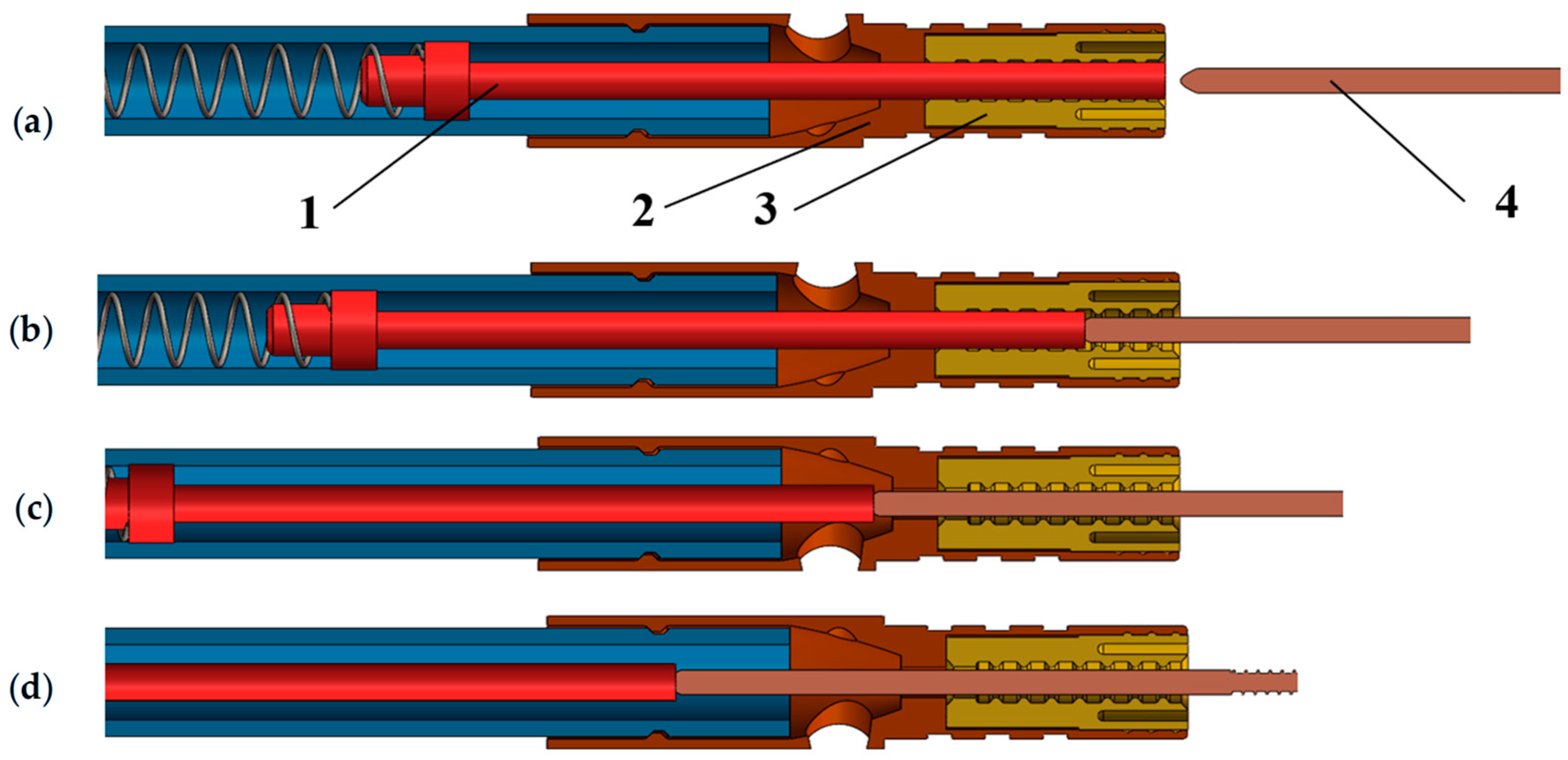
As shown in
Figure 2, the working process of this sealing structure can be divided into four stages: (a) In the initial state, the entrance casing undergoes elastic deformation under the preloading force of the bushing, forming a stable contact interface with the sleeve, thereby achieving static sealing; (b) During the pin advancement stage, the entrance casing dynamically contacts the sleeve, pin, and bushing, creating multiple sealing interfaces and forming a continuous sealing path; (c) During the pin engagement stage, the entrance casing, pin, and protective sleeve undergo deformation, maintaining dynamic sealing through interference contact; (d) In the fully mated state, once the pin establishes a stable electrical connection with the socket conductor, the interference fit between the bushing and the entrance casing forms the final sealing state, ensuring long-lasting sealing of the internal medium. The process during separation is the reverse of the above.
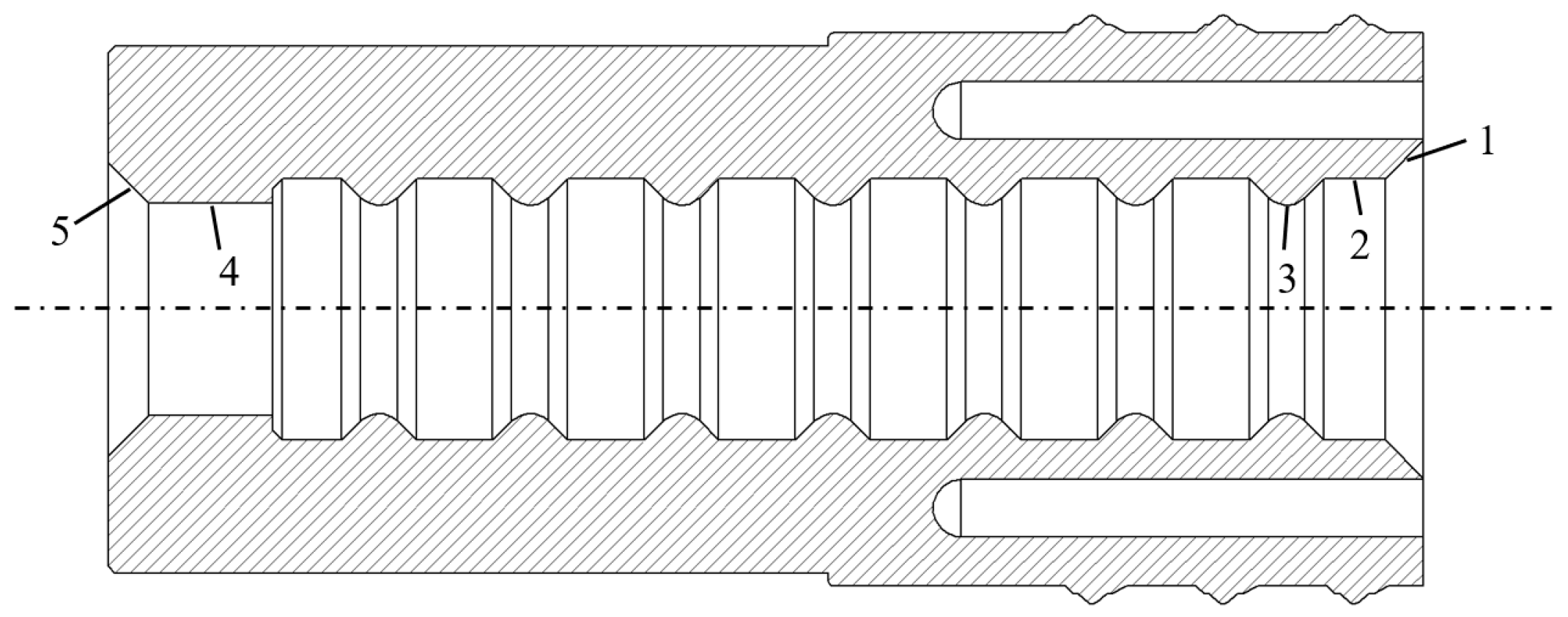
The subsea wet-mate connector employs a sealing-sleeve assembly to realize dynamic sealing. As illustrated in
Figure 3, the entrance casing is installed within the bushing, and its bore is axially partitioned into a lead-in section, a preload land, an annular sealing-protrusion section, a stabilizing land, and an exit section. Prior to insertion, the preload land—implemented as a local bulge on the sleeve’s outer diameter—produces a radial interference fit with the bushing, thereby establishing an external static seal at the entrance casing–bushing interface and providing structural restraint. As the pin enters, the lead-in (chamfer) profile guides the pin and allows elastic outward flaring of the terminal protrusion, reducing the initial insertion force. During advancement, the ribs in the annular sealing-protrusion section successively engage and slide against the pin’s outer surface, forming a migrating dynamic sealing band, while the upstream region not yet reached by the pin remains statically sealed by the entrance casing–sleeve interface, ensuring continuity of the sealing path. The stabilizing land limits the radial deformation of the sleeve, maintains concentricity, and smooths load transfer, thereby preventing local instability and the opening of leakage paths in the dynamic-sealing zone. Upon full seating, the exit section is interference-compressed against the end of the bushing bore; together with the compressed ribs and the preload land, the inner interfaces in contact with the pin transition from dynamic to static sealing, yielding a two-stage series static-seal configuration—outer (entrance casing–bushing) and inner (ribs–pin). This configuration achieves a low insertion force while ensuring long-term sealing reliability under deep-sea high-pressure, low-temperature, and corrosive conditions.
4. Sealing Determination Theory
The sealing reliability of subsea wet-mateable connectors depends on the contact pressure on the inner wall of the entrance casing. When the contact pressure formed by the entrance casing, sleeve, and pin exceeds the pressure differential between the internal and external media, the seal is considered effective. However, if the contact pressure is insufficient to withstand the pressure differential, leakage occurs at the interface, leading to failure [
21].
Figure 5 illustrates the dynamic sealing structure. The entrance casing, as the core sealing component, achieves dynamic contact with the sleeve and pin through an interference fit design. The inner diameter of the entrance casing is matched with the outer diameter of the corresponding components to generate a preset interference fit. Additionally, during the installation of the entrance casing, it is subjected to radial load from the external housing, which creates an initial contact pressure
Pl between the sealing surfaces. When the pressure differential of the working medium is absent or small, the seal ring maintains sealing solely through its inherent elastic preload. Once a pressure differential develops across the cavity, pressure assistance increases the elastic deformation, and the interfacial contact pressure becomes the sum of the medium-induced pressure differential
Pj and the initial contact pressure
Pl. Accordingly, reliable dynamic sealing is achieved only if the contact pressure on the sealing surface exceeds the applied internal–external pressure differential of the connector:
In the equation, is the maximum contact stress.
The underwater wet-mateable connector maintains dynamic equilibrium between the internal silicone oil pressure and seawater pressure at rest through a pressure balancing system. Under dynamic conditions, the oil flow between the three chambers must pass through internal channels or valves for exchange. Due to flow resistance, changes in oil pressure lag behind fluctuations in external pressure. During the pin insertion process, the silicone oil pressure increases while the seawater pressure remains unchanged, causing the oil pressure to be slightly higher than the seawater pressure. During the pin extraction process, the silicone oil pressure decreases while the seawater pressure remains unchanged, causing the oil pressure to be slightly lower than the seawater pressure. In practical applications, since the insertion and extraction process occurs in deep-water environments, the tolerance of the pin and the mechanical vibrations caused by insertion require the contact pressure to be significantly higher than the internal and external pressure differential of the connector to ensure reliable connections under complex conditions. According to the literature, the maximum pressure differential is recognized to be 5 MPa, and with a safety factor of 1.5, the contact pressure on the inner wall of the entrance casing must be at least 7.5 MPa [
22].
5. Simulation Analysis
This study uses the four-core socket single-core structure as the analysis unit, as shown in
Figure 6. The entrance casing adopts an axial 20 mm cylindrical structure, with inner and outer diameters of 5.2 mm and 8.5 mm, respectively. The insertion end contains an annular space and an entry chamfer, and the inner wall is equipped with 10 sets of protrusions. The outer diameters of the pin and sleeve are both 5 mm.
The pin and sleeve are made of beryllium bronze, while the material for the entry sleeve is selected as fluororubber. For the fluororubber material, the hyperelastic Mooney–Rivlin model is used. The calculated properties and relevant technical data are provided in
Table 2.
5.1. Simulation Results Analysis
Under the 1500 m water depth condition, the Underwater wet mateable connector was simulated with a friction coefficient of 0.05 between the entrance casing, sleeve, and pin, and a preset radial interference of 0.01 mm. The simulation analyzed the sealing characteristics during the insertion of the pin at a speed of 10 mm/s.
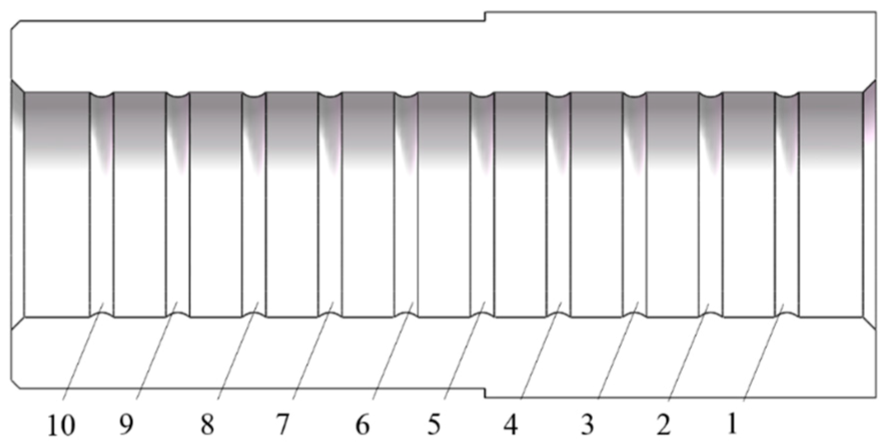
The sealing capability depends on the pressure generated by the contact between the annular protrusions and the pin. The 10 sets of annular protrusions inside the entrance casing are labeled sequentially from 1 to 10, starting from the entry (
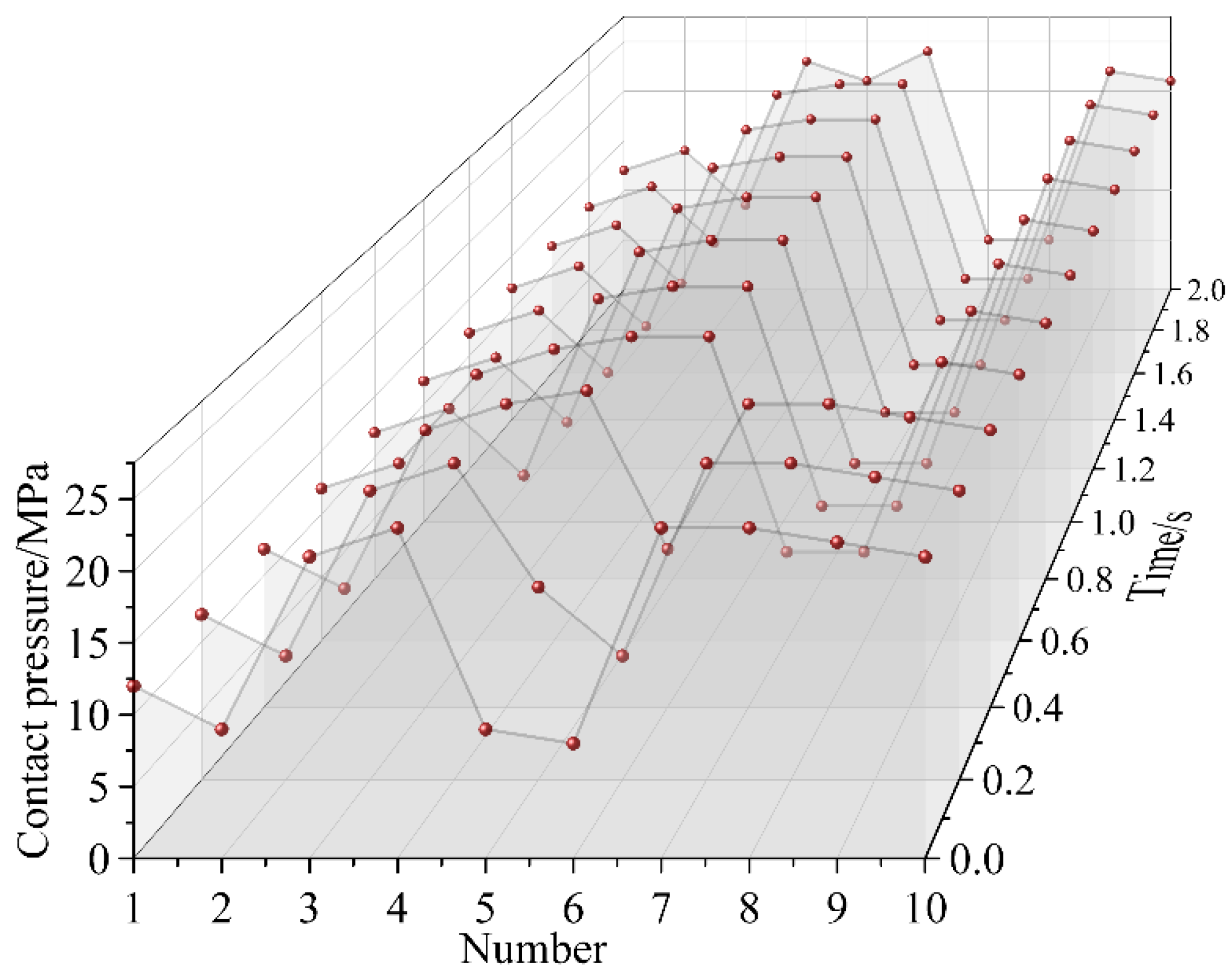
Figure 7). The average contact pressure time-sequence distribution of each protrusion during the simulation (0–2 s) is shown in
Figure 8, reflecting the variation in contact stress with pin motion.
Figure 8 shows that during the mating process, the contact pressure of each protrusion on the entrance casing fluctuates regularly, with the pressure at the first and last protrusions remaining stable. The pressure at protrusion 1 stabilizes around 14 MPa, as there are no protrusions in contact with the pin before it, resulting in no compressive force from prior protrusion deformation. The pressure at protrusion 10 stabilizes around 21 MPa due to the deformation of the first nine protrusions, which transfers compressive force to protrusion 10. The peak contact pressure occurs in the middle region of the entrance casing, around 24 MPa, and shifts inward as the pin progresses.
Sealing performance depends on whether the peak contact pressure reaches the threshold. Therefore, the key node corresponding to the minimum contact pressure during motion must be selected for further study. Data analysis shows that the contact pressure reaches its lowest point at 1.6 s. At this time, the equivalent stress, total deformation, contact stress, and frictional stress distribution characteristics of the entrance casing are as shown in
Figure 9 and
Figure 10.
As shown in
Figure 9, the larger equivalent stress in the entrance casing is concentrated at nodes 1 to 4, with positions 1 and 2 being particularly prominent. This is due to fact that the initial sealing rings, being the first to engage with the pin, are required to accommodate the greatest initial interference fit. This necessitates substantial radial deformation to facilitate the penetration path for the pin, thereby generating the highest level of contact stress. Concurrently, the axially decaying gradient of frictional forces induced during the insertion process subjects the foremost rings to the most intense compressive state, whereas the subsequent rings operate under progressively diminished mechanical loading. Functioning as the primary sealing barrier, these front-line rings leverage their superior contact pressure to establish fundamental sealing integrity and effectively scrape off the vast majority of external contaminants. The right end, being the critical sealing area, experiences the maximum equivalent stress of 16.297 MPa, which is below the yield strength of the fluororubber material (25 MPa), thus meeting the sealing structure’s strength requirements. However, since this analysis uses a simplified model, the right-side annular space design does not reflect real-world conditions. Nonetheless, the equivalent stress and deformation on the right side are still greater than on the left side, suggesting the need for reinforcement of the right-side structure or an increase in sleeve thickness to prevent sealing failure.
As shown in
Figure 10a, the maximum contact pressure inside the sleeve occurs at protrusions 6 and 7, with values exceeding 7.5 MPa, meeting the sealing requirements. The contact pressure of protrusions 6–10 is slightly higher than that of protrusions 1–5, indicating that the right-side annular space design plays a buffering role in pressure and bears significant equivalent stress and deformation. The left side, with higher and stable contact pressure, forms the primary sealing area, improving sealing reliability.
Figure 10b shows that the frictional stress changes in sync with the contact pressure, as it is determined by the product of the contact pressure and friction coefficient. The cumulative frictional force in the sleeve is calculated as approximately 38.3 N, based on the product of the average stress of each annular protrusion and the contact area. According to the structural design of the four-core connector, the total resistance to be overcome during mating/demating operations is 153.2 N (four times the single-core frictional force).
5.2. Analysis of the Influence of Various Factors
5.2.1. Influence of Protrusion Shape on Contact Pressure
The circular protrusion is the most common type of protrusion used in the dynamic sealing of the entry casing. Additionally, trapezoidal and blade-like protrusions are also applied in dynamic seals, as shown in
Figure 11.
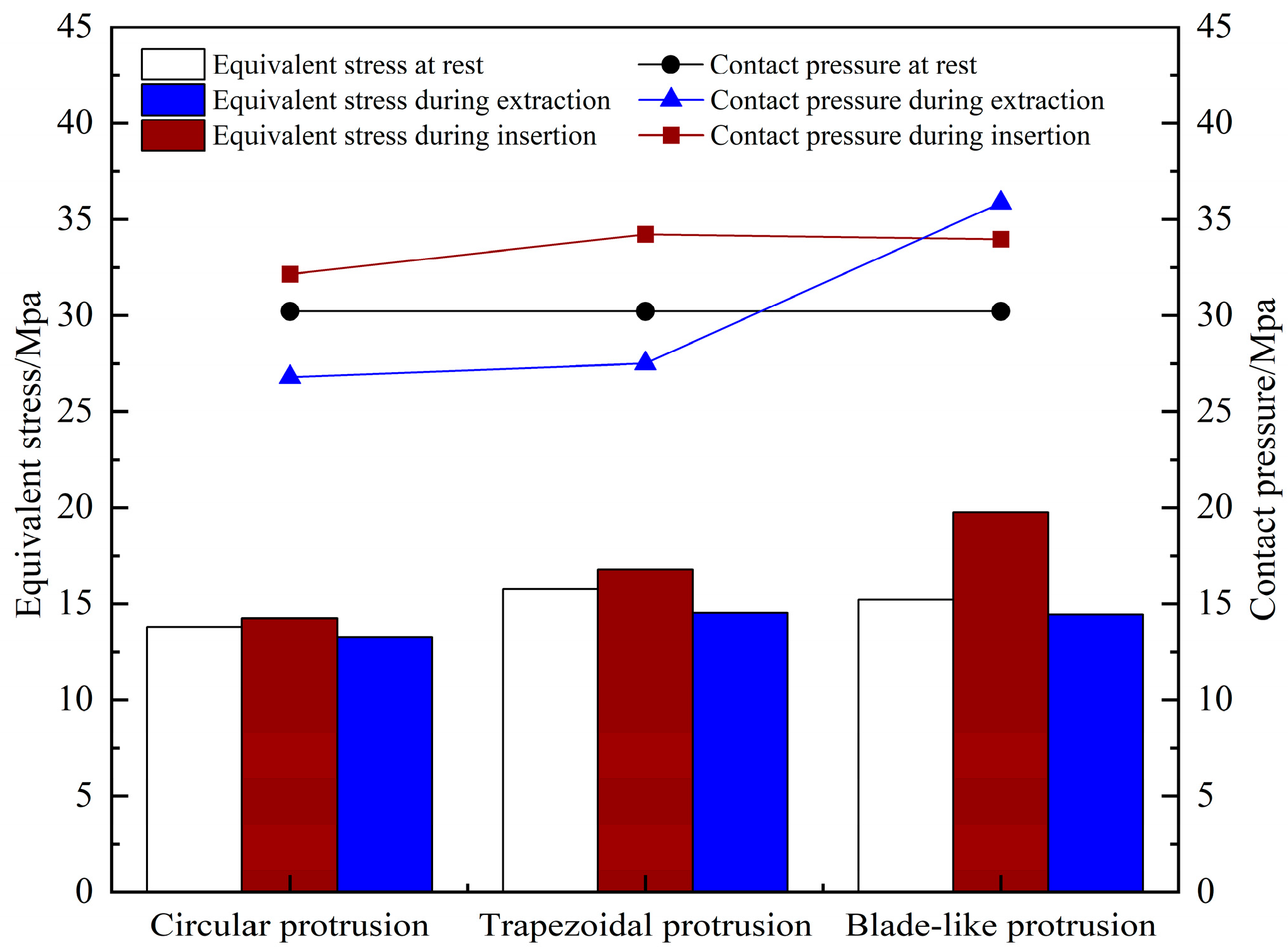
Using the method of controlling variables, only the shape of the protrusions in the sleeve model is changed, while the interference fit and friction coefficient remain unchanged. The simulation analysis process is repeated, and the simulation results of contact pressure and equivalent stress under different protrusion shapes are shown in
Figure 12.
Figure 12 shows that the equivalent stress during insertion for both the blade-shaped and trapezoidal protrusions is higher than that of the circular protrusion. The blade-shaped protrusion reaches 19.76 MPa, and during extraction, its contact pressure increases by nearly 10 MPa compared to the trapezoidal protrusion. Deformation and tearing were observed at the blade-shaped protrusion during simulation, making it unsuitable for multiple insertions and extractions. When comparing the circular and trapezoidal protrusions, the equivalent stress in all three states for the trapezoidal protrusion is higher than that of the circular one, due to its larger contact area under the same radial expansion. During both insertion and extraction, the contact pressure of the trapezoidal protrusion exceeds that of the circular one, indicating better sealing performance. However, it requires greater insertion and extraction force to switch between working states. Consequently, both protrusion types will be retained, and separate simulations will be conducted for each type in the subsequent variable analyses.
5.2.2. Influence of Insertion/Extraction Speed on Contact Pressure
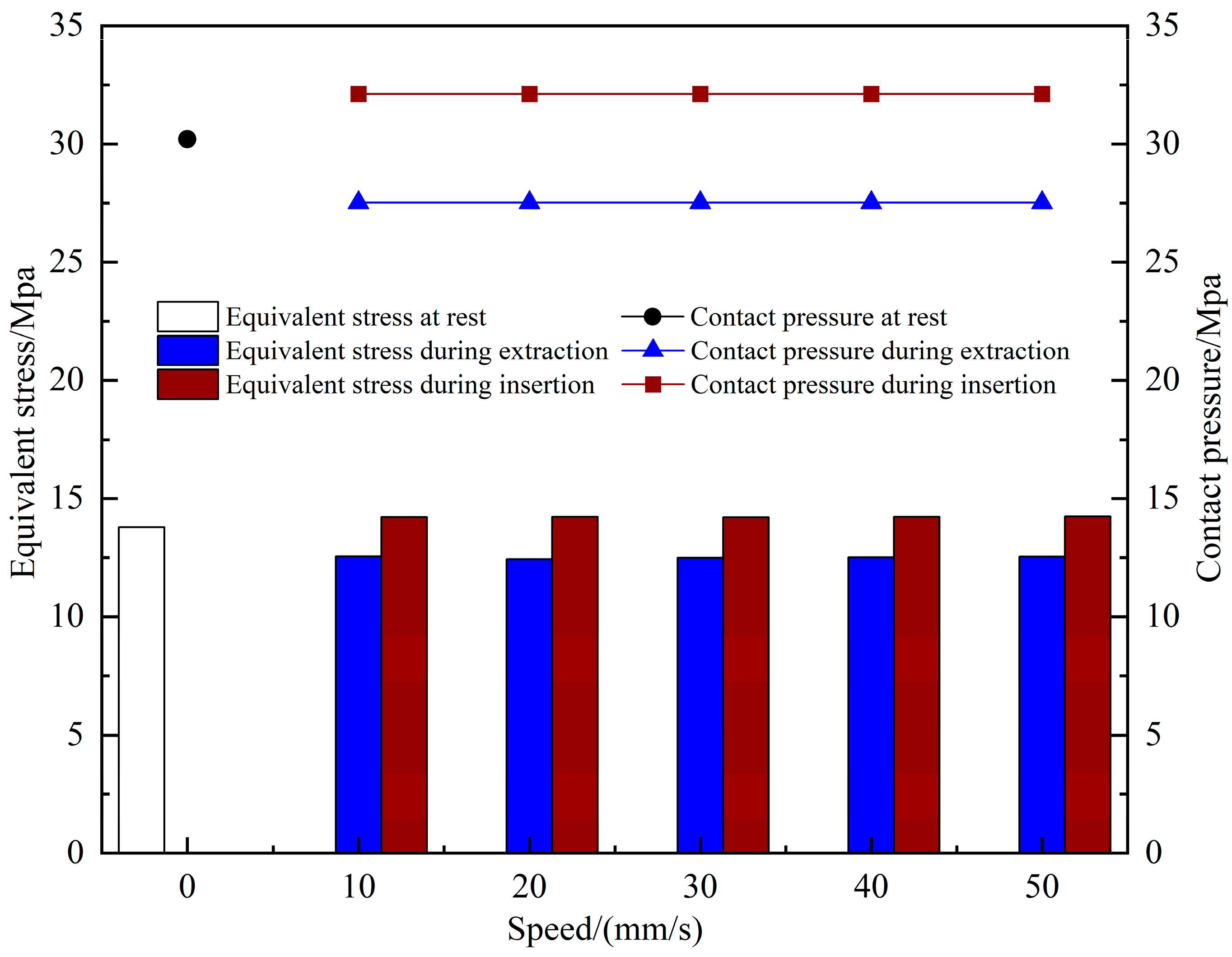
To evaluate the impact of insertion/extraction speed on dynamic sealing performance, simulations were conducted with the following conditions: the radial expansion of the entrance casing was set at 0.01 mm, and the inner surface friction coefficient at 0.1. The simulation covered the entire process, from initial contact between the sleeve and pin to their complete separation. By varying the insertion/extraction speeds (10, 20, 30, 40, and 50 mm/s), five simulations were run, maintaining a consistent motion path and time parameter. The distribution of equivalent stress and contact pressure at different speeds is compared and shown in
Figure 13.
As shown in
Figure 13, the contact pressure at the protrusion position inside the entrance casing remains largely unchanged across the five different insertion/extraction speeds. The equivalent stress fluctuates by no more than 0.2 MPa during both insertion and extraction. The contact pressure during extraction stabilizes at 27.5 MPa, while during insertion it stabilizes at 32.1 MPa, with the resting pressure at 30.2 MPa. The maximum equivalent stress on the inner side of the entrance casing is higher during insertion than extraction, with the resting value at 13.8 MPa, between the insertion and extraction values. In conclusion, insertion/extraction speed has minimal impact on both equivalent stress and contact pressure. Additionally, at all speeds, the contact pressure during extraction is lower than during insertion, making dynamic sealing performance during extraction weaker than during insertion, thus representing the weaker link in the mating process.
5.2.3. Influence of Friction Coefficient on Contact Pressure
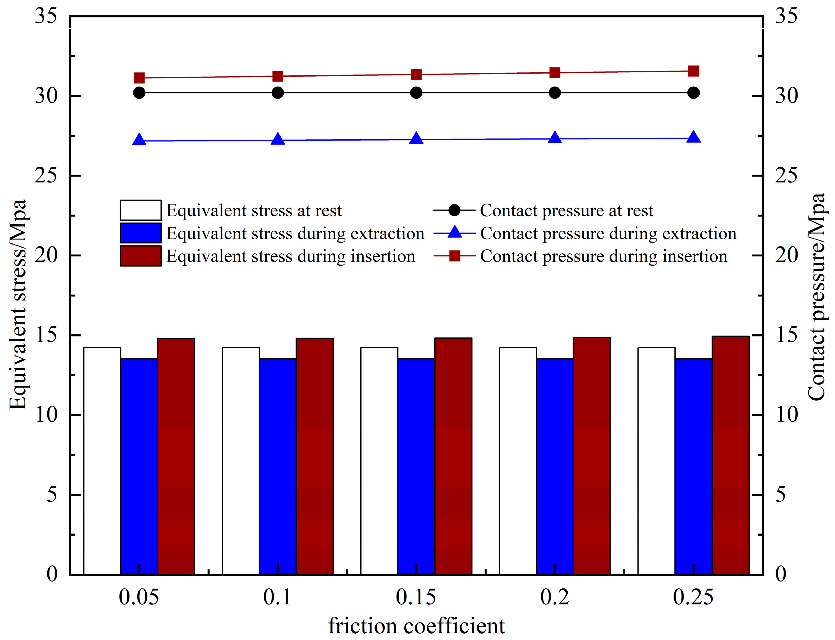
To investigate the impact of the dynamic friction coefficient on sealing performance, simulations were conducted under the following conditions: the radial expansion of the entrance casing was 0.01 mm, and the insertion/extraction speed was 10 mm/s. The dynamic friction coefficient of the inner surface was varied at 0.05, 0.10, 0.15, 0.20, and 0.25, with a consistent motion path and controlled time parameter. Five complete insertion/extraction simulations were performed. The distribution of equivalent stress and contact pressure under different friction conditions is compared in
Figure 14.
As shown in
Figure 14, as the friction coefficient increases, the contact pressure of the dynamic seal gradually rises during both insertion and withdrawal. With friction coefficients of 0.05, 0.1, 0.15, 0.2, and 0.25, the insertion contact pressure increases from 31.13 MPa to 31.57 MPa, and the withdrawal contact pressure increases from 27.19 MPa to 27.35 MPa, with the static pressure stabilizing at 30.21 MPa. The equivalent stress on the inner wall of the entrance casing stabilizes at 14.83 MPa, 14.22 MPa, and 13.53 MPa during insertion, static, and withdrawal states, respectively. In summary, an increase in the friction coefficient enhances the contact pressure during the dynamic process, thereby improving dynamic sealing performance. However, changes in the friction coefficient have minimal impact on the stress conditions of the entrance casing.
5.2.4. Influence of Radial Expansion on Contact Pressure
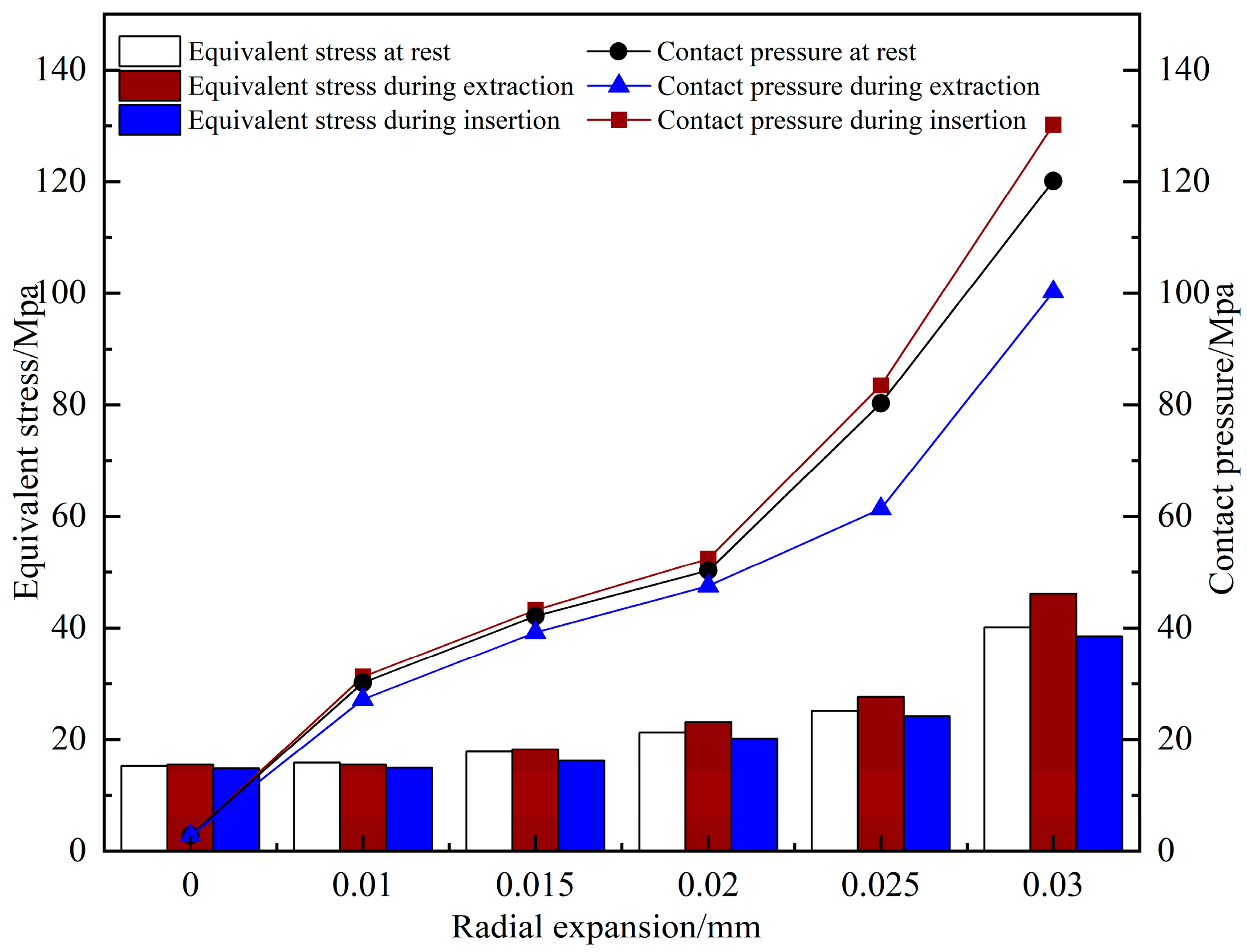
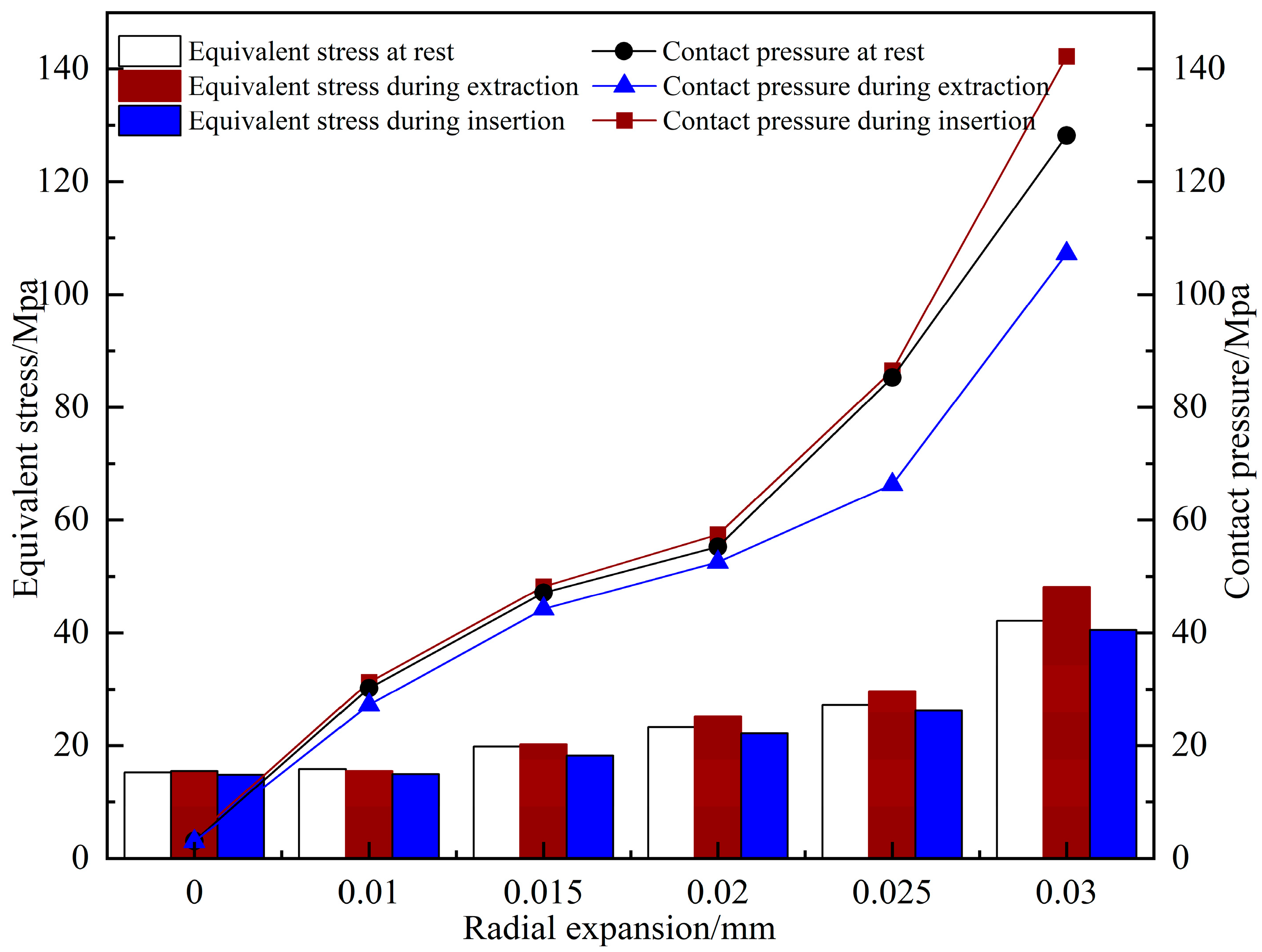
The dynamic friction coefficient of the entry casing is set to 0.1, and the insertion and withdrawal speed is 10 mm/s. The radial compression of the entry casing is varied at 0, 0.01, 0.015, 0.02, 0.025, and 0.03. Simulation analyses are conducted for both circular and trapezoidal protrusions, with the motion path and time held constant. The simulation results of equivalent stress and contact pressure under different radial compression values are shown in
Figure 15 and
Figure 16.
Figure 15 and
Figure 16 show that when radial expansion is zero, contact pressure is still generated on the inner protrusion surface of the entrance casing due to pre-tightening and medium-induced pressure differential. The contact pressure for the circular protrusion is approximately 3 MPa, and for the trapezoidal protrusion, it is about 3.5 MPa. These values do not meet the minimum dynamic sealing requirements. As radial expansion increases, the contact pressure significantly rises. At 0.01 mm radial expansion, the minimum contact pressure for both protrusions exceeds 7.5 MPa, meeting sealing requirements. The contact pressure continues to increase with radial expansion, with the trapezoidal protrusion showing higher and more rapid increases due to its larger contact area.
To ensure sealing reliability, the equivalent stress must remain below the rubber material’s yield strength of 25 MPa. At a radial expansion of 0.025 mm, the equivalent stress for the circular protrusion reaches 25.17 MPa, exceeding the yield strength. For the trapezoidal protrusion, the equivalent stress at a radial expansion of 0.02 mm during insertion reaches 25.24 MPa, also exceeding the yield strength. These conditions do not meet the working requirements. While increasing radial expansion improves contact pressure and dynamic sealing performance, excessive compression raises equivalent stress and risks structural failure. Considering both sealing performance and material yield strength, a radial expansion of 0.02 mm for the circular protrusion or 0.015 mm for the trapezoidal protrusion should be selected to ensure safe and reliable dynamic sealing.
5.3. Friction Force Analysis During Insertion/Extraction
The sealing contact surface inside the entrance casing generates frictional force during the insertion/extraction process, with its magnitude largely influenced by the contact pressure. An optimal frictional force ensures smooth insertion/extraction while maintaining the seal when the pin is not inserted, preventing seawater pressure from forcing the sleeve inward and compressing the spring, which could cause leakage. However, excessive friction increases the difficulty of pin insertion/extraction, and repeated cycles lead to greater wear on the rubber material, reducing sealing performance and connector lifespan. Furthermore, if the frictional force exceeds the spring’s rebound capacity, the sleeve may fail to return to the right end of the entrance casing during extraction, compromising sealing capability.
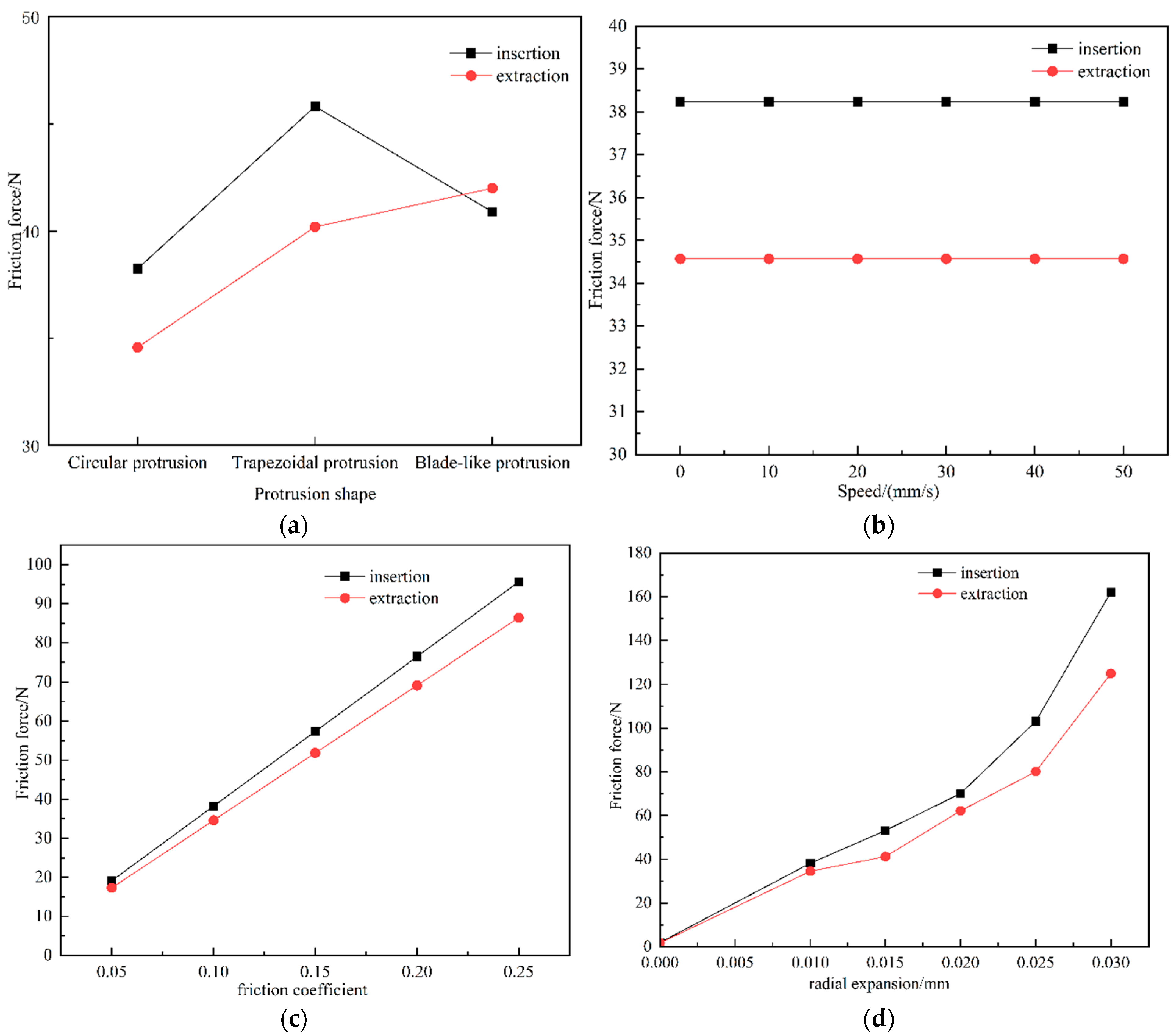
By performing simulation analysis under various conditions, the distribution of equivalent stress in the entrance casing can be determined. By combining the contact area with the data, the frictional force during the insertion/extraction process can be calculated. Based on the simulation results, friction force variation patterns for different protrusion shapes, insertion/extraction speeds, friction coefficients, and compression values were derived, as shown in
Figure 17.
As shown in
Figure 17, the trapezoidal protrusion, due to its larger contact area, generally generates more frictional force than the circular protrusion. The blade-shaped protrusion experiences damage during the extraction process and will not be considered further. Frictional force is influenced by both contact pressure and the friction coefficient, and they are positively correlated. The insertion/extraction speed has no significant effect on the frictional force, while an increase in Radial expansion significantly enhances the frictional force.
In practical applications, the wet-mate connector must overcome the frictional force at the contact surfaces, the spring reset force, and fluid resistance. The maximum frictional force is limited by the insertion/extraction force, and it must be within a reasonable range to ensure operational feasibility. The maximum frictional force is specified to not exceed 280 N. Therefore, the maximum frictional force per pin in a four-core connector must not exceed 70 N. The trapezoidal protrusion can be selected, but the Radial expansion must not exceed 0.015 mm, and the friction coefficient on the inner side of the entrance casing must not exceed 0.15. For this design, the trapezoidal protrusion, with a Radial expansion of 0.015 mm, an insertion/extraction speed of 20 mm/s, and a friction coefficient of 0.15, results in an average insertion/extraction force of 197.26 N for the four-core connector. This data is specific to the four-core connector design. If the connector is made into a 12-core configuration, the maximum frictional force per pin would be smaller. In that case, the trapezoidal protrusion would no longer meet the requirements for both sealing and stable insertion/extraction. Therefore, a circular protrusion would be selected, and other parameters would also need to be adjusted accordingly.
6. Hydrostatic Pressure Testing
Subsea wet-mateable connectors require the establishment of a comprehensive sealing verification system, which simulates deep-sea conditions through standardized pressure chamber testing. Static pressure resistance verification is conducted according to GJB 7244-2011 [
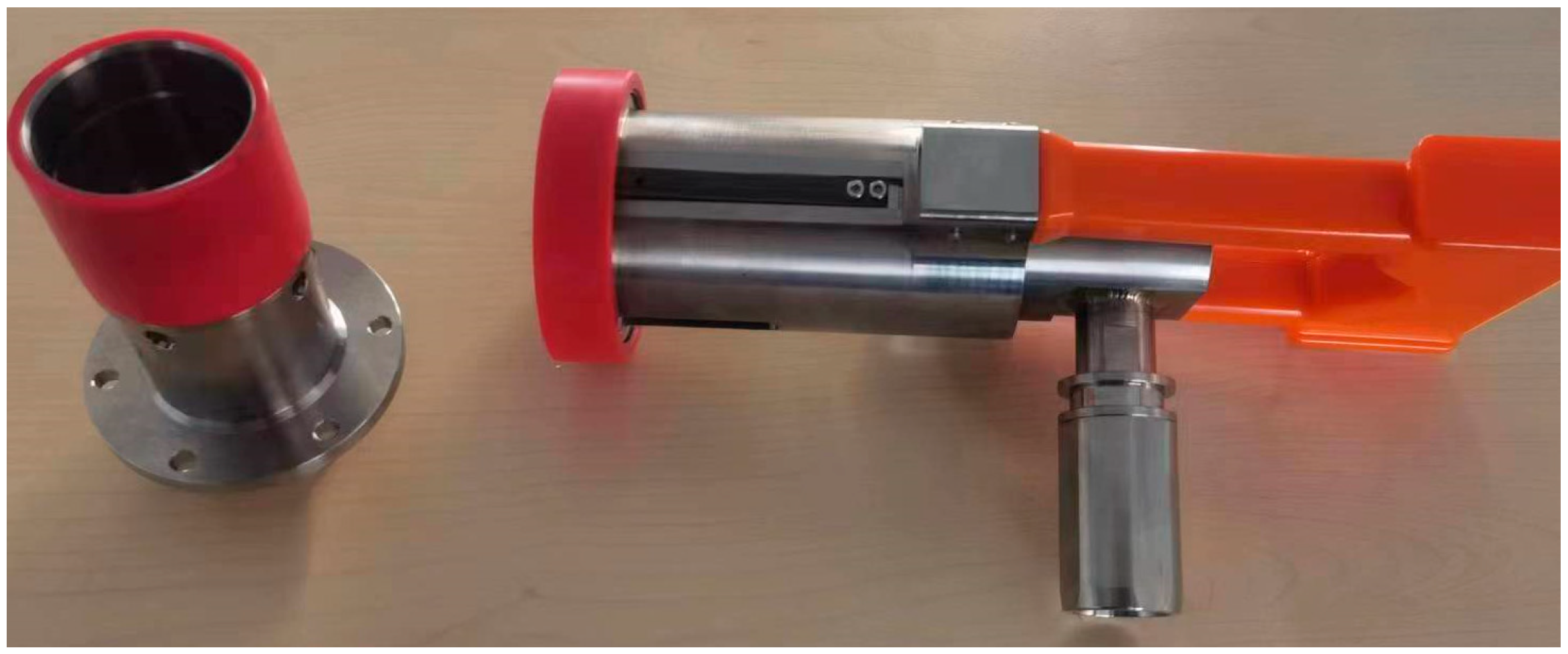
23], including two testing modes: sustained static load and cyclic pressure. Subsea wet-mateable connectors are shown in
Figure 18.
The working water depth of a subsea wet-mateable connectors developed in this study is 1500 m. During testing, the pressure should be selected to be higher than the water depth for strength testing, with 20 MPa being chosen. The connected and disconnected connectors should be able to withstand the specified water pressure to ensure sealing. After removing the tested equipment from the container, it should first be air-dried. Then, the insulation resistance of the connected state should meet the specifications in
Table 3 [
23].
The experimental procedure is shown in
Table 4. The plug connector and socket connector are separated, and water is added to fill the container, ensuring the container pressure reaches the specified pressure. After the test, the water pressure is unloaded, the connector is removed, and after natural air drying, the insulation resistance is measured.
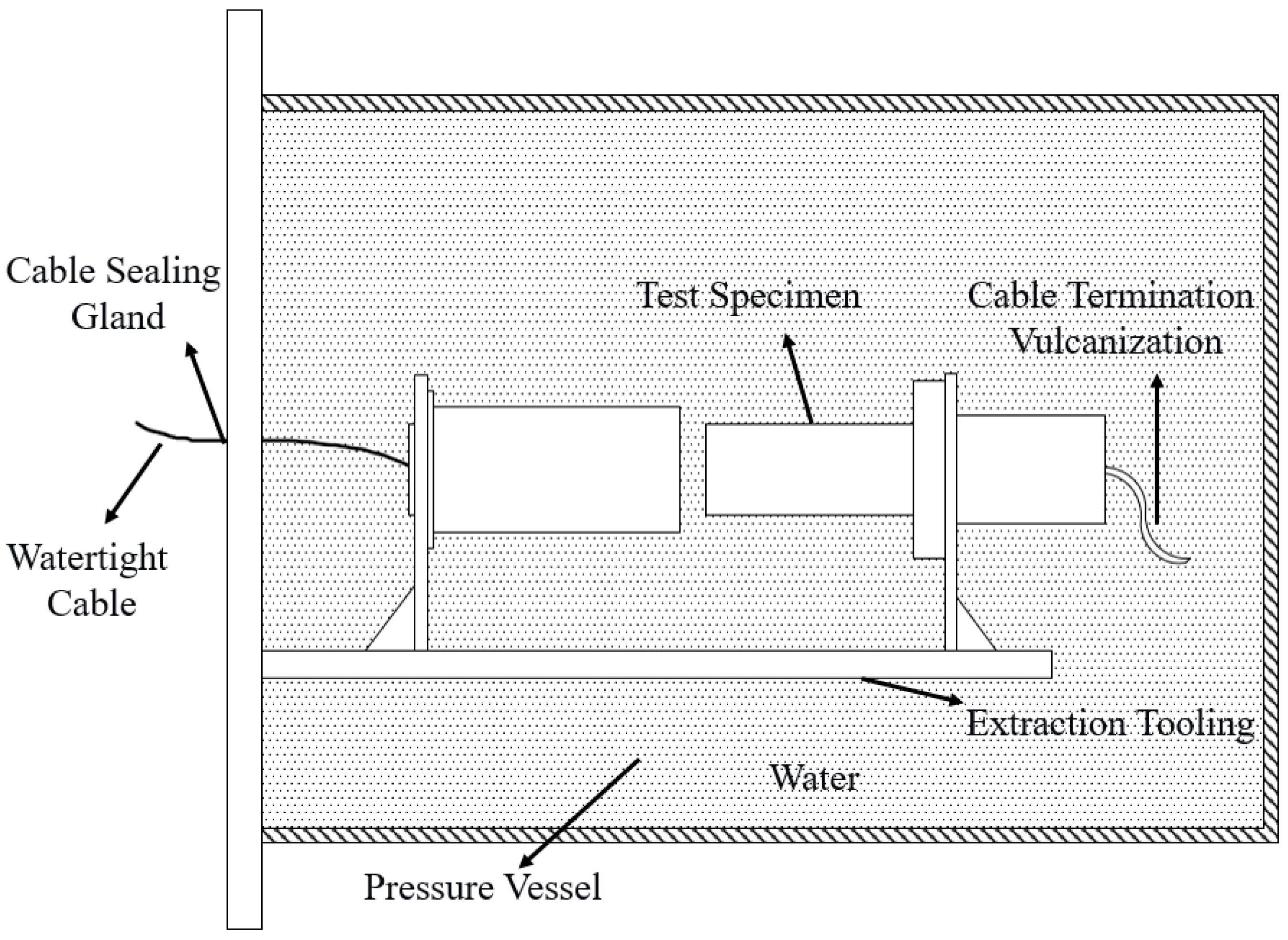
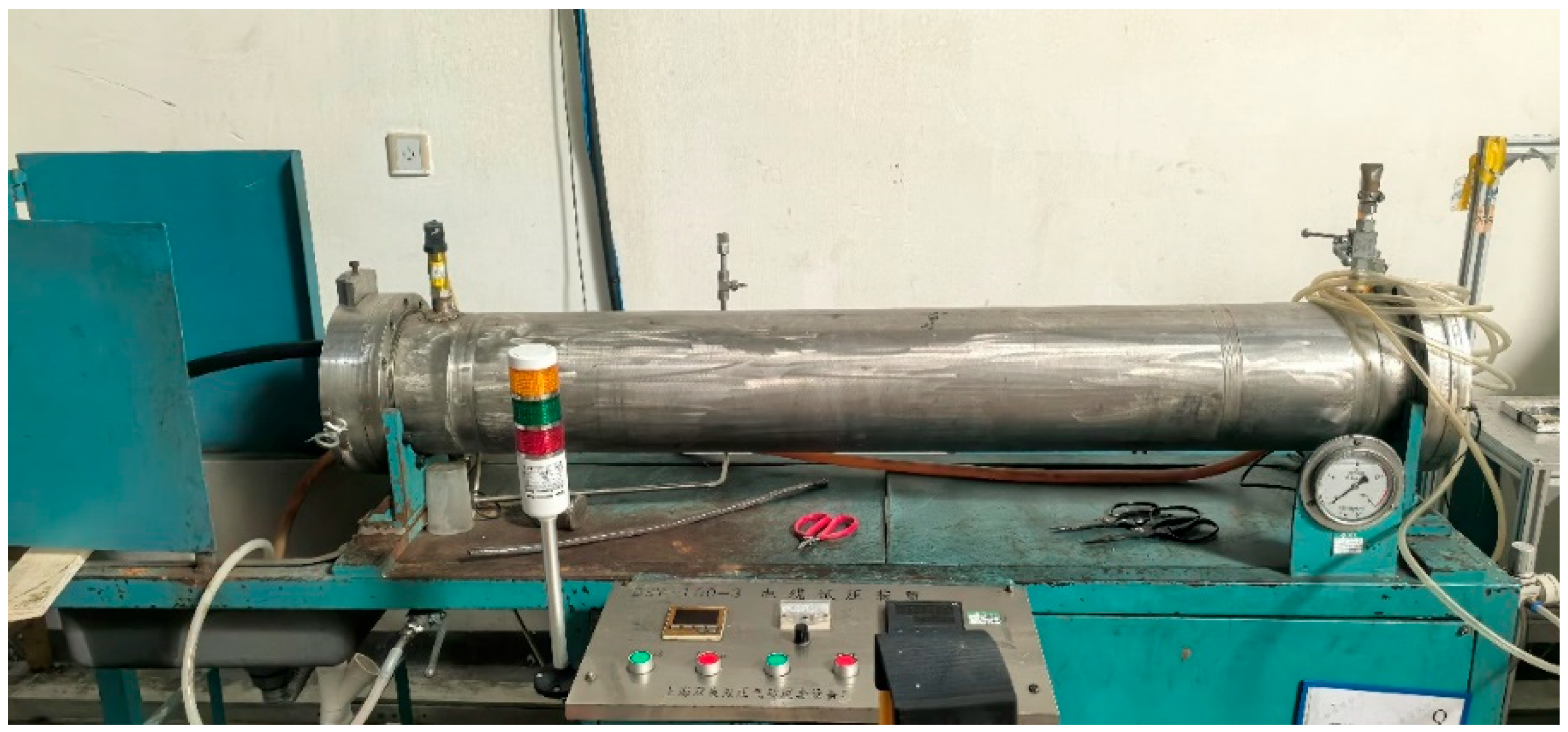
The tested equipment is installed in the pressure vessel, which is then filled with fresh water. The pressure vessel is gradually pressurized to 20 MPa. After testing, the connector is inspected for mechanical damage and water leakage. Once the sample is removed and naturally air-dried, the insulation resistance should meet the detailed specifications. The pressure testing apparatus is shown in
Figure 19 and
Figure 20.
The test results show that there is no noticeable damage to the connector cable assembly and the connection part of the pin core. After natural air drying, the measured insulation resistance, as shown in
Table 5, meets the test requirements and complies with the operating condition design.
