Article

Study and Optimization of Shore-to-Ship Underwater Capacitive Power Transfer System Considering Parasitic Coupling

1
School of Electrical Engineering, Naval University of Engineering, Wuhan 430030, China
2
Department of Electrical Engineering, Kunming University of Science and Technology, Kunming 650500, China
*
Authors to whom correspondence should be addressed.
Actuators 2025, 14(11), 534; https://doi.org/10.3390/act14110534
Submission received: 8 September 2025 / Revised: 14 October 2025 / Accepted: 31 October 2025 / Published: 5 November 2025
(This article belongs to the Special Issue Power Electronics and Actuators—Second Edition)

Abstract

The increasing trend towards electrification in transportation highlights the potential for electric ships and the demand for safe, rapid charging systems. Underwater capacitive power transfer (UCPT) is considered a suitable solution due to its high power density potential. This article presents research on and optimization of UCPT for shore-to-ship charging in freshwater environments. It proposes a design for an insulation coupler and explores the influence of parasitic capacitance in the environment. This study demonstrates how the ship and shore impact the coupler’s coupling coefficient and mutual capacitance, thereby affecting the power and efficiency. Through theoretical calculations and finite element analysis, a kW-level UCPT coupler is designed. Experimental verification under different cases confirms the efficiency and constant current output characteristics, with superior performance observed when the coupler is positioned further away from the ship or shore. This study showcases the potential of UCPT to provide reliable and efficient power supply for electric ships, while emphasizing the importance of considering environmental factors and parasitic effects in system design and operation. These findings contribute to advancing UCPT technology and offer insights for further optimization to enhance practical applicability.

1. Introduction

With the increasing global energy demand and growing environmental concerns, the electrification trend of transportation vehicles has become more evident. All-electric ships, which utilize batteries as the sole power source, are a type of electric vehicle. Compared to traditional fuel-powered ships, all-electric ships not only have lower pollution and energy consumption but also offer features such as quietness and comfort [1,2,3]. With advancements in key technologies for battery energy storage systems and motor drive systems, all-electric ships have encountered new development opportunities. They have broad prospects in areas such as urban passenger and sightseeing transportation, inland waterway freight transport, and lake surveillance and governance. However, the range of electric ships is limited due to the large size and weight of batteries, as well as the high initial investment. Fast and efficient charging has become an important factor in further promoting the development of electric ships.
Although traditional wired charging can achieve high power, it requires a significant amount of manpower to handle heavy cables and ensure precise alignment of charging interfaces. Moreover, plug connections with metal contacts are prone to leakage, wear, and oxidation, posing significant safety hazards. Additionally, the charging process is susceptible to environmental and weather conditions due to the difficulty of waterproofing the charging interface.
Wireless power transfer (WPT) technology addresses many of the drawbacks of traditional wired charging methods. WPT systems eliminate the need for cable connections between ships and shore, enabling safer and more convenient connection and disconnection. The charging process is not affected by environmental and weather conditions. Furthermore, the operational and maintenance costs are greatly reduced. Over the past decade, WPT has undergone revolutionary development, achieving significant improvements in transfer power, efficiency, and distance [4,5,6,7].
In the context of electric ship charging, WPT can be implemented above the water surface [8,9,10] or underwater [11,12,13]. Wireless transfer on the water surface obstructs navigation and cargo handling, and introduces additional safety issues. Even when wireless transfer is conducted above the water surface, the system still needs to be completely waterproof. Therefore, underwater wireless power transfer is a more suitable solution.
Based on their working principles, WPT systems can be classified into near-field and far-field types. The far-field method includes techniques such as microwave, laser, and ultrasonic power transfer. These methods can achieve long-range transmission, but the power they transfer is relatively low, making them unsuitable for electric ship charging applications. In contrast, near-field WPT technologies, including inductive power transfer (IPT) and capacitive power transfer (CPT), are more commonly used in scenarios requiring short-range, high-power transmission.
Although IPT has been more extensively studied, the complexity of the coupler structure presents challenges in terms of reliability and cost-effectiveness. IPT requires coils and ferrites to generate and guide magnetic fields [14,15,16,17]. Coils often use expensive Litz wire, and ferrites are heavy and fragile. Additionally, IPT is highly sensitive to metallic foreign objects, which limits its practicality in wireless charging scenarios for electric ships [18]. In contrast, CPT only requires a few metal plates to generate an electric field [19,20]. As a result, the coupler can easily achieve waterproofing and withstand high pressure in deep water. Furthermore, CPT is generally less sensitive to the presence of metallic foreign objects. This is because the electric field is more confined, and the interactions mainly lead to charge redistribution rather than generating significant eddy current heating, which improves safety and reliability [21,22,23]. Importantly, the permittivity of water is 81 times that of air, greatly increasing the coupling capacitance [24,25,26]. Therefore, underwater capacitive wireless power transfer (UCPT) has the potential to achieve high power density.
Previous UCPT research can be categorized into two types. The first type focuses on non-insulated couplers, which include bare metal plates. In [27,28], only milliwatt-level power and a transfer distance of 5 mm were achieved. In [29,30], a distance of 20 mm and a power of 400 W were realized. In [31], a stacked-type coupler was applied for underwater transfer, although its performance was inferior to that of a horizontal coupler. In conclusion, while freshwater can be used as the dielectric material in capacitive systems, it still possesses weak conductivity. In high-power applications, water losses increase, and insulation breakdown becomes an issue.
Insulated couplers are considered the second type of UCPT. In [32], an insulated coupler was applied to achieve long-distance transfer of 500 mm with a power of 219 W. Ref. [33] also provided the design of an insulated coupler and conducted low-power verification at a distance of 8 mm with a power of 47 W. In [34], only half of the coupler was insulated, which was reported to enhance performance, achieving a power transfer of 38.8 W and an efficiency of 34.85%. In [35], the UCPT power was increased to 1 kW, with an efficiency of 74%. In conclusion, insulated couplers mitigate issues such as electric shock, breakdown, and oxidation, demonstrating significant potential for high-power transmission.
However, previous studies mostly employed simple LC compensation networks and did not include rectifiers in the system [27,28,29,30,32,33]. Such low-level power can only be used for underwater sensors or autonomous underwater vehicles (AUVs) charging. For charging electric ships, even small vessels require power levels of at least kilowatts. Furthermore, previous research did not consider the influence of the UCPT coupler in the environment, especially the parasitic capacitance between the ship’s metallic hull and the shore.
This paper proposes the design of an insulated coupler. The modeling of the coupler considers not only coupling capacitance and cross capacitance but also the influence of parasitic capacitance caused by the ship’s hull and the shore. Subsequently, finite element analysis (FEA) is used to research the insulation and optimize the coupling coefficient. Finally, a high-order compensation network is employed in the UCPT system to achieve high-power transfer of 3.3 kW.
The key novel contributions of this work are threefold: (1) the development of a comprehensive UCPT coupler model that explicitly incorporates the parasitic effects of the ship’s metallic hull and the conductive shore, which are critical for practical design but often overlooked; (2) a systematic finite-element-analysis-based investigation and optimization of the coupler’s placement relative to the hull and shore to maximize the coupling coefficient; and (3) the experimental validation of a high-power UCPT system for electric ships, which demonstrates the performance gains achieved through the optimized coupler design and the use of a high-order M-M compensation network.
The organization of the rest of the paper is as follows: Section 2 introduces the structure of the UCPT system for electric ships. Section 3 presents the modeling and design of the coupler. Section 4 describes the design of the compensation network. Section 5 presents the experimental validation. Section 6 concludes the paper and discusses further implications.

2. Underwater Capacitive Power Transfer System for Electric Ships

The underwater capacitive power transfer system for electric ships is shown in Figure 1. The shore is considered as the primary side of the transfer, including the DC power supply, inverter, and compensation network. The ship is considered as the secondary side of the transfer, including the compensation network, rectifier, and battery load. Between the primary and secondary sides, the coupler is the core component of the power transfer, comprising four metal plates labeled P1 to P4. These plates are fixed to a mechanical arm to facilitate alignment and maintain a fixed transmission distance. Compared to CPT systems in air environments [36], the plates used for underwater CPT can be much smaller, enabling a simpler mechanical arm design. Additionally, the mechanical arm used for wireless charging can be integrated with the ship’s mooring system, thereby enhancing the overall system integration.
As shown in Figure 1, P1 and P2 are positioned on the shore, while P3 and P4 are embedded in the ship. With water as the dielectric, a coupling capacitance is formed between P1 and P3, as well as between P2 and P4. Therefore, the four plates form a complete circuit. The transfer of power is dominated by displacement current between the plates. Due to the small value of the coupling capacitance, compensation networks are necessary to compensate for the large reactance caused by the small capacitance. Another function of the compensation network is to elevate the plate voltage to achieve lower displacement current and reduce losses.
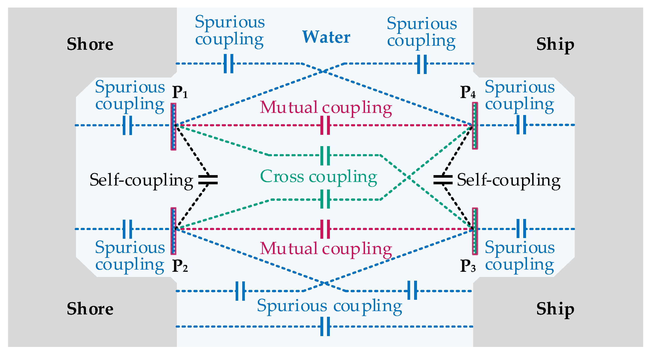
However, considering the practical charging environment, it is not sufficient to only consider the two coupling capacitances. On the one hand, there are additional parasitic capacitances in the system. As shown in Figure 2, these parasitic capacitances originate from the cross-coupling between the plates, the coupling between the same-side plates, the coupling between the plates and the metal hull of the ship, and the coupling between the plates and the shore. Some of these parasitic capacitances can even be larger than the coupling capacitance, so they cannot be neglected in the coupler modeling. On the other hand, since water has weak conductivity, all the coupling and parasitic capacitances should have a small conductance (or large resistance) in parallel.
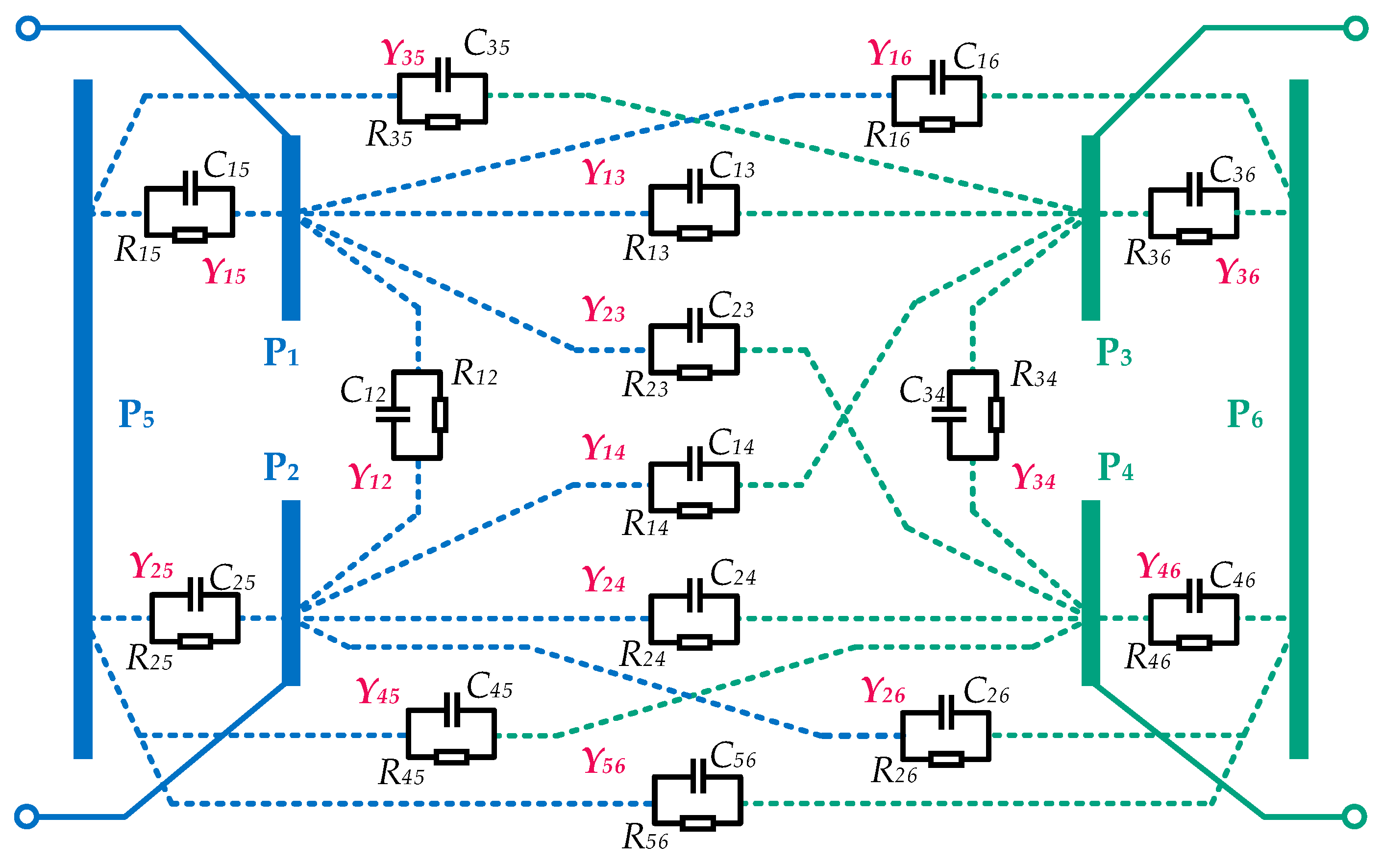
Based on the above considerations, the model of the coupler is illustrated in Figure 3. The four power transfer plates are represented as P1 − P4. The shore, which is considered as the ground, has a certain conductivity and can be regarded as having equal potential everywhere. In modeling, the ground is generally treated as an independent plate [37,38]. The metal hull of the ship is treated as another independent plate. In Figure 3, the shore and the ship are denoted as P5 and P6, respectively. Using flat plates to represent the shore and the hull is a standard initial approach for capturing the main parasitic coupling effects without introducing excessive geometric complexity. Future work could adopt more realistic 3D structures for a more accurate representation.
According to Figure 3, the proposed model consists of 6 plates and includes a total of 15 admittances. Each admittance is composed of a capacitance and a resistance in parallel.

3. UCPT System for Electric Ships

3.1. Simplification and Equivalence of the Coupler Model

The full-admittance model of the coupler is illustrated in Figure 3. These 15 admittances can be expressed as follows:
Y m n = j ω C m n + 1 R m n ( m = 1 , 2 , 3 , 4 , 5 , 6 ; n = 1 , 2 , 3 , 4 , 5 , 6 . )
Each admittance can be further represented by the coupling capacitance and quality factor. In a freshwater capacitive coupler, the quality factors of individual capacitors are approximately equal [32,39]. Therefore, the quality factor is defined as:
Q = ω C m n R m n ( m = 1 , 2 , 3 , 4 , 5 , 6 ; n = 1 , 2 , 3 , 4 , 5 , 6 . )
Hence, Equation (1) can also be expressed as:
Y m n = ω C m n ( j + 1 Q ) ( m = 1 , 2 , 3 , 4 , 5 , 6 ; n = 1 , 2 , 3 , 4 , 5 , 6 . )
Since P1 and P2 are connected to the transmitting circuit, P3 and P4 are connected to the receiving circuit, and P5 and P6 are not connected to any circuit, they can be divided into three ports. Port 1 consists of P1 and P2, Port 2 consists of P3 and P4, and Port 3 consists of P5 and P6. Thus, the complete admittance model of the coupler can be transformed into a three-port model, as shown in Figure 4. The voltages and currents at the three ports are denoted as Va, Ia, Vb, Ib, Vc, and Ic, respectively. They satisfy the following expressions:
I a I b I c = Y a Y a b Y a c Y a b Y b Y b c Y a c Y b c Y c V a V b V c ,
where Ya, Yb, and Yc represent the self-admittance of each port, and Yab, Yac, and Ybc represent the mutual admittance between ports. The nodal voltage method [40,41] can be employed to solve for these parameters. Therefore, the admittance parameters of the three-port model are expressed as:
Y a = Y 12 + ( Y 13 + Y 14 ) ( Y 23 + Y 24 ) Y 13 + Y 14 + Y 23 + Y 24 + ( Y 15 + Y 16 ) ( Y 25 + Y 26 ) Y 15 + Y 16 + Y 25 + Y 26 Y b = Y 34 + ( Y 13 + Y 23 ) ( Y 14 + Y 24 ) Y 13 + Y 14 + Y 23 + Y 24 + ( Y 35 + Y 36 ) ( Y 45 + Y 46 ) Y 35 + Y 36 + Y 45 + Y 46 Y c = Y 56 + ( Y 15 + Y 25 ) ( Y 16 + Y 26 ) Y 15 + Y 16 + Y 25 + Y 26 + ( Y 35 + Y 45 ) ( Y 36 + Y 46 ) Y 35 + Y 36 + Y 45 + Y 46 Y a b = Y 13 Y 24 Y 14 Y 23 Y 13 + Y 14 + Y 23 + Y 24 Y a c = Y 15 Y 26 Y 16 Y 25 Y 15 + Y 16 + Y 25 + Y 26 Y b c = Y 35 Y 46 Y 36 Y 45 Y 35 + Y 36 + Y 45 + Y 46 .
As P5 and P6 are floating, i.e., Ic = 0, Figure 4 can be further simplified into a two-port model as shown in Figure 5. The voltages and currents at the two ports are denoted as V1, I1, V2, and I2, respectively. They satisfy the following expressions:
I 1 I 2 = Y 1 Y M Y M Y 2 V 1 V 2 ,
where Y1 and Y2 represent the self-admittance of each port, and YM represents the mutual admittance between ports. Similarly, the nodal voltage method [37,38] can be utilized to solve for these parameters. Therefore, the admittance parameters of the two-port model are expressed as:
Y M = Y a b + Y a c Y b c Y c Y 1 = Y a Y a c 2 Y c Y 2 = Y b Y b c 2 Y c .
Combining Equations (3), (5) and (7), the equivalent capacitance in the two-port model can be expressed as:
Y M = ω C M ( j + 1 Q ) Y 1 = ω C 1 ( j + 1 Q ) Y 2 = ω C 2 ( j + 1 Q ) C M = C 13 C 24 C 14 C 23 C 13 + C 14 + C 23 + C 24 + C a c C b c C c C 1 = C 12 + ( C 13 + C 14 ) ( C 23 + C 24 ) C 13 + C 14 + C 23 + C 24 + ( C 15 + C 16 ) ( C 25 + C 26 ) C 15 + C 16 + C 25 + C 26 C a c 2 C c C 2 = C 34 + ( C 13 + C 23 ) ( C 14 + C 24 ) C 13 + C 14 + C 23 + C 24 + ( C 35 + C 36 ) ( C 45 + C 46 ) C 35 + C 36 + C 45 + C 46 C b c 2 C c
where
C a c = C 15 C 26 C 16 C 25 C 15 + C 16 + C 25 + C 26 C b c = C 35 C 46 C 36 C 45 C 35 + C 36 + C 45 + C 46 C c = C 56 + ( C 15 + C 25 ) ( C 16 + C 26 ) C 15 + C 16 + C 25 + C 26 + ( C 35 + C 45 ) ( C 36 + C 46 ) C 35 + C 36 + C 45 + C 46
CM in Equation (8) is referred to as the mutual capacitance. C1 and C2 represent the self-capacitance of the primary and secondary sides, respectively. Thus, the coupling coefficient of the coupler is defined as follows:
k C = C M C 1 C 2
The definition of the coupling coefficient shown in Equation (10) is the most commonly used representation in CPT. It measures the strength of the useful capacitive coupling (CM) relative to the parasitic coupling to the environment (C1, C2). A higher kc value means that a larger proportion of the effective electric field in the charged state is used for power transmission across the gap, rather than dissipating into the surrounding environment, which is directly related to higher potential efficiency. Additionally, it forms a dual relationship with the definition in IPT [42].
The coupling coefficient serves as an important indicator for optimizing the CPT coupler. Previous studies have demonstrated a relationship between transfer efficiency and the coupling coefficient [21,42,43], as expressed as follows:
η = k C 2 Q 2 ( 1 + 1 + k C 2 Q 2 ) 2

3.2. Coupler Dimension Configuration

Finite element analysis (FEA) is a commonly used method for designing coupler parameters [11,32,35,44]. In this work, a coupler model was established in Maxwell. The solution region was determined to be 1300 mm × 800 mm × 300 mm based on laboratory conditions, consistent with the dimensions of the water tank. Freshwater with a relative permittivity of 81 and a conductivity of 0.0002 S/m was filled in the solution region. This value was chosen to establish a performance baseline by mitigate ohmic losses in the water, thereby allowing the feasibility of the proposed high-power UCPT system and the effects of coupler optimization to be clearly isolated and validated [32,45]. The Solution type was set as AC conduction, and the analysis frequency was 1 MHz.
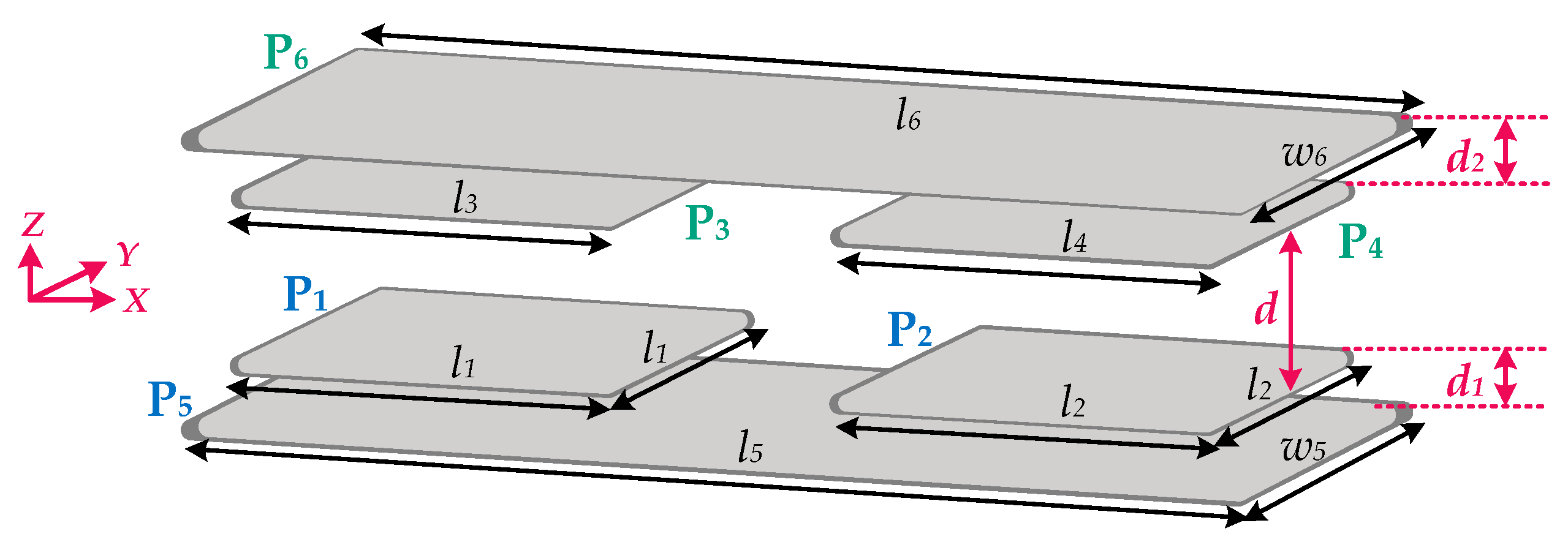
The proposed coupler model and its dimensions are shown in Figure 6 and Figure 7. P1 − P4 are power transfer plates, while P5 and P6 represent shore and ship sides, respectively. To simplify the design, P1 − P4 are all square aluminum plates with side lengths represented by l1 − l4. P5 and P6 are both rectangular aluminum plates with dimensions of l5 × w5 and l6 × w6, respectively. To approach reality as closely as possible, P5 and P6 need to fully cover P1 − P4. The distances between the edges of P5 and P6 and P1 − P4 are represented by le1 − le4. The horizontal distances between P1 and P2 and between P3 and P4 are ls1 and ls2, respectively. The vertical distances between P1 and P2 and between P5 are d1, while the vertical distances between P3 and P4 and between P6 are d2. The transfer distance is represented by d.
Considering laboratory conditions, the side length of the power transfer plates P1 − P4 is specified as 200 mm. Horizontal distances ls1 and ls2 are specified as 100 mm, while le1 − le4 are specified as 15 mm. Therefore, the dimensions of P5 and P6, which serve as shore and ship substitutes, are both 530 mm × 230 mm. The thickness of all aluminum plates is 2 mm. To ensure that the coupler can withstand high voltage for higher transfer power, all aluminum plates are covered with a 1 mm thick insulation layer. The insulation layer is made of FR4 material with a relative permittivity of 4.4. Therefore, the dimensions to be studied and optimized are the transfer distance d, as well as the distances d1 and d2 between the power transfer plates and the shore and ship, respectively.
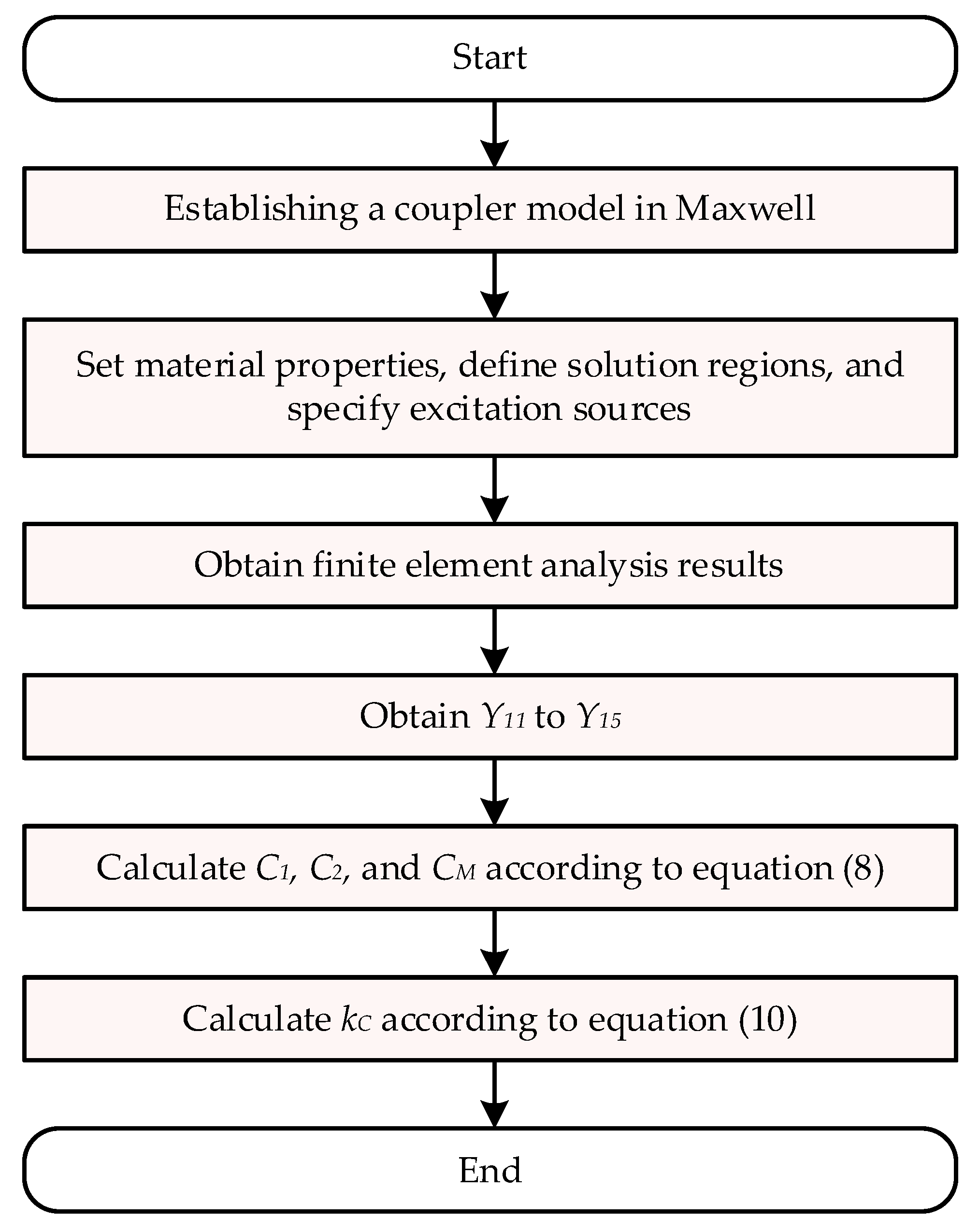
To obtain the values of CM, C1, C2, and kC for each size of the coupler, the process shown in Figure 8 can be followed. First, a 3D model of the coupler must be created using FEA software. The FEA software used in this study is ANSYS Maxwell 2022 R2. Next, material properties, solution region, excitation sources, and other system parameters are set in Maxwell software. After setting up the parameters, a simulation is run to obtain the FEA results. From these results, the 15 admittance parameters (Y12 to Y56) are extracted. Using Equations (4)–(9), the values of CM, C1, and C2 can be calculated. Finally, the coupling coefficient can be obtained using Equation (10).

3.3. Characteristics Analysis of Coupler

In a typical transfer scenario, the transfer distance is limited. In other words, the design objective is to achieve a specific transfer distance. In this work, the target transfer distance is set at 50 mm, and the impact of the distance between the coupler and the shore and ship on the transfer is investigated. This optimization process is carried out using FEA. By analyzing how the coupling coefficient kC varies with the distances d1, d2, and d, the optimal placement of the coupler can be determined.
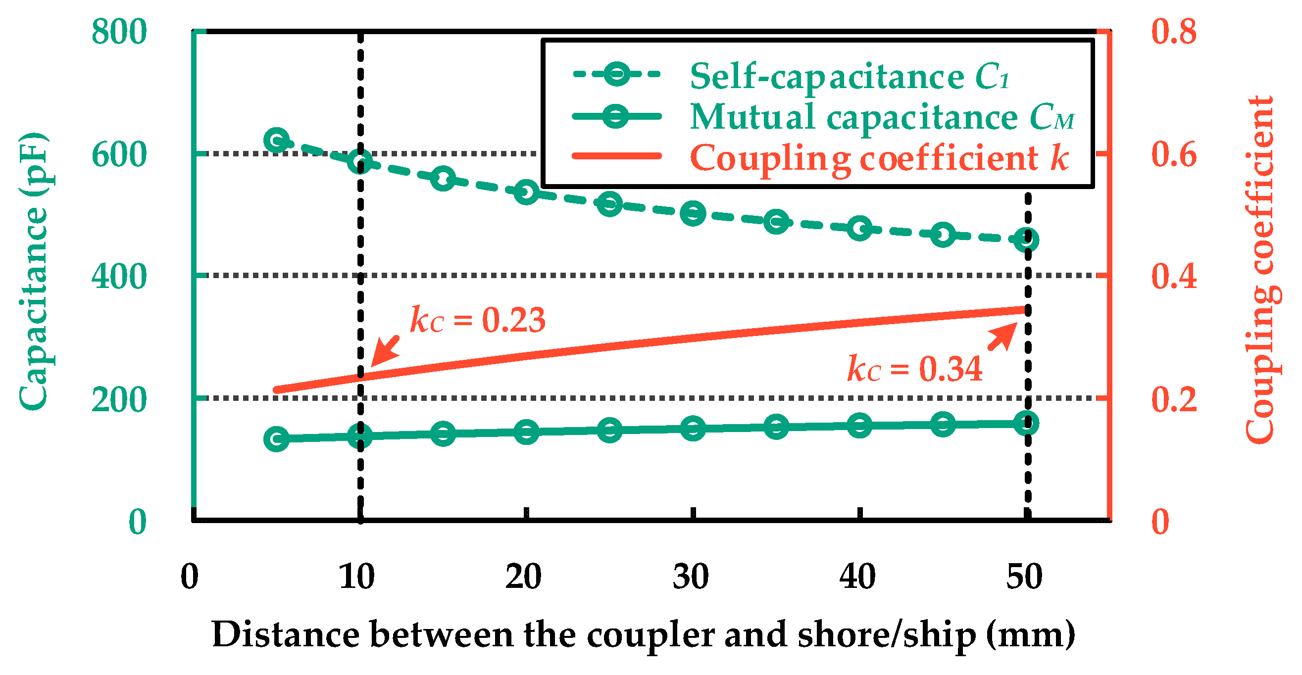
Figure 9 illustrates the FEA results of the equivalent self-capacitance, mutual capacitance, and coupling coefficient of the coupler as the distance between the coupler and the shore and ship varies when d = 50 mm. To simplify the analysis, let d1 = d2. As d1 increases from 5 mm to 50 mm, the mutual capacitance increases from 132.32 pF to 158.22 pF, while the self-capacitance decreases from 621.74 pF to 458.85 pF. Since the transfer distance remains constant, the change in mutual capacitance is relatively small. However, the self-capacitance of the coupler is significantly affected by the ship and shore, resulting in an impact on the coupling coefficient. As d1 increases from 5 mm to 50 mm, the coupling coefficient increases from 0.21 to 0.34. According to Equation (11), to maintain high transfer efficiency, the coupler needs to be positioned farther away from the ship and shore.
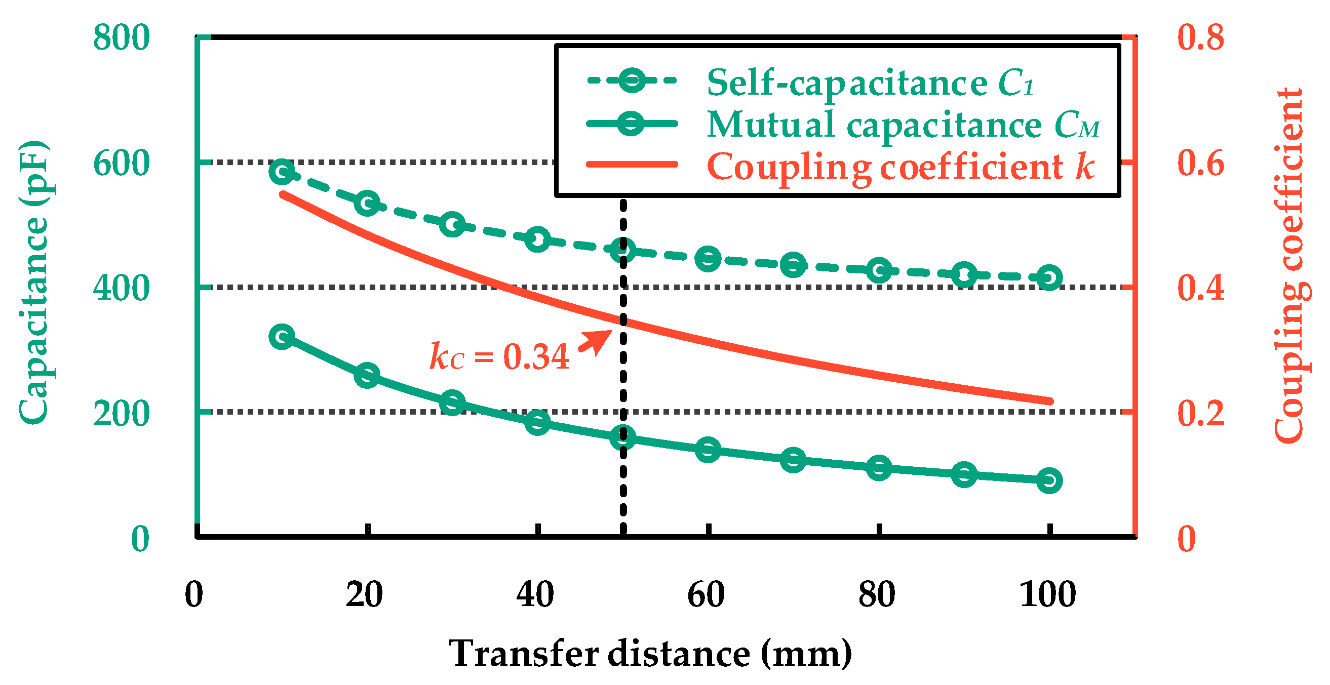
Figure 10 presents the FEA results of the equivalent self-capacitance, mutual capacitance, and coupling coefficient of the coupler as the transfer distance varies when d1 = d2 = 50 mm. As d increases from 10 mm to 100 mm, the mutual capacitance decreases from 320.54 pF to 90.15 pF, and the self-capacitance decreases from 584.65 pF to 414.938 pF. Therefore, both the mutual capacitance and self-capacitance decrease significantly with increasing transfer distance. However, due to the larger influence of the transfer distance on the mutual capacitance, the coupling coefficient also decreases significantly with increasing transfer distance. As d increases from 10 mm to 100 mm, the coupling coefficient decreases from 0.55 to 0.22. Consequently, achieving high-efficiency transfer at longer transfer distances becomes challenging. For d = 50 mm, the coupling coefficient is 0.34.
Based on the results shown in Figure 9 and Figure 10, it can be reasonably inferred that for relatively efficient underwater capacitive power transfer, the transfer distance should not be too far. Additionally, at a specific transfer distance, the coupler should not be positioned too close to the shore and ship.
In this work, d = 50 mm is chosen. This distance is selected to perform basic validation of the proposed coupler model and compensation network under high power levels, within the constraints of the current experimental conditions.
With d = 50 mm fixed, the configuration of d1 = d2 = 50 mm is the optimized solution for maximizing kC. To further validate the optimization results obtained in this section, two operating conditions are used for comparative verification: case 1 with d1 = d2 = 10 mm, and case 2 with d1 = d2 = 50 mm. The subsequent sections will present the design and verification of the UCPT system for each of these cases.

4. Compensation Network Design

4.1. Compensation Network Structure

In the scenario of high-power wireless charging for ships, the load is a large-capacity battery, making high-power constant current charging desirable. The compensation network prioritizes the use of a constant current topology, with the S-S topology being the simplest and most widely used compensation network structure [46].
Figure 11 illustrates the UCPT system with an S-S compensation network. Here, Vin represents the DC voltage source. S1 − S4 are MOSFETs that form a full-bridge inverter. The inverter outputs voltage and current as U1 and I1, respectively. CM, C1, and C2 denote the equivalent capacitance of the coupler. L1 and L2 represent the primary and secondary compensating inductors, respectively. D1 − D4 are diodes that form a full-bridge rectifier. The input voltage and current of the rectifier are U2 and I2, respectively. Vout represents a constant-voltage load, simulating the battery pack.
According to Ref. [42], the resonance condition can be expressed as:
ω = 2 π f = 1 L 1 C 1 ( 1 k C 2 ) = 1 L 2 C 2 ( 1 k C 2 )
where f′ denotes the inverter switching frequency and ω′ represents the angular frequency. Under resonance, the output current can be expressed as:
I 2 = j ω C M ( 1 k C 2 1 ) U 1
This indicates that the output current is independent of the load, allowing constant current output to be achieved. The transfer power can be further expressed as:
P = ω C M ( 1 k C 2 1 ) U 1 U 2
From Equation (14), in the case of a relatively small coupling capacitance CM, to increase power, the coupling coefficient must be reduced. This implies a decrease in efficiency. Therefore, the basic S-S compensation network is not suitable for high-power transfer.
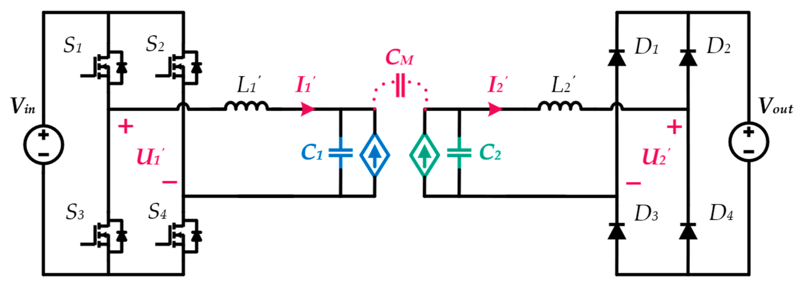
Figure 12 illustrates a UCPT system with an M-M compensation network. The only difference from Figure 11 lies in the compensation network. Lf1 and L1 form a mutual inductance M1 with a coupling coefficient of kL1. Lf2 and L2 form a mutual inductance M2 with a coupling coefficient of kL2. Their relationship can be expressed as:
M 1 = k L 1 L f 1 L 1 M 2 = k L 2 L f 2 L 2
Hence, this is a higher-order compensation network. In comparison with other widely used higher-order compensation networks such as double-sided LCLC, LCL, CLL, etc., the M-M network offers higher integration and greater design flexibility.
In Figure 12, the output voltage and current of the inverter are denoted as U1 and I1, while the input voltage and current of the rectifier are represented as U2 and I2. According to Ref. [47], the resonance condition can be expressed as:
ω = 2 π f = 1 L f 1 C f 1 = 1 L f 2 C f 2 = 1 L 1 C 1 ( 1 k C 2 ) = 1 L 2 C 2 ( 1 k C 2 )
where f represents the inverter switching frequency and ω denotes the angular frequency. Under resonance, the output current can be expressed as:
I 2 = j U 1 ω 3 M 1 M 2 C M ( 1 k C 2 1 )
This indicates that the output current is independent of the load. Therefore, the M-M compensation network also exhibits constant current output characteristics. The transfer power can be further expressed as:
P = U 1 U 2 ω 3 M 1 M 2 C M ( 1 k C 2 1 )
From Equation (18), power enhancement can be achieved by adjusting M1 and M2, which are only related to the parameters of the compensation network. This means that achieving high power no longer necessitates sacrificing the coupling coefficient. This is why higher-order compensation networks are more suitable for high-power applications compared to the simple S-S topology.

4.2. Parameter Design

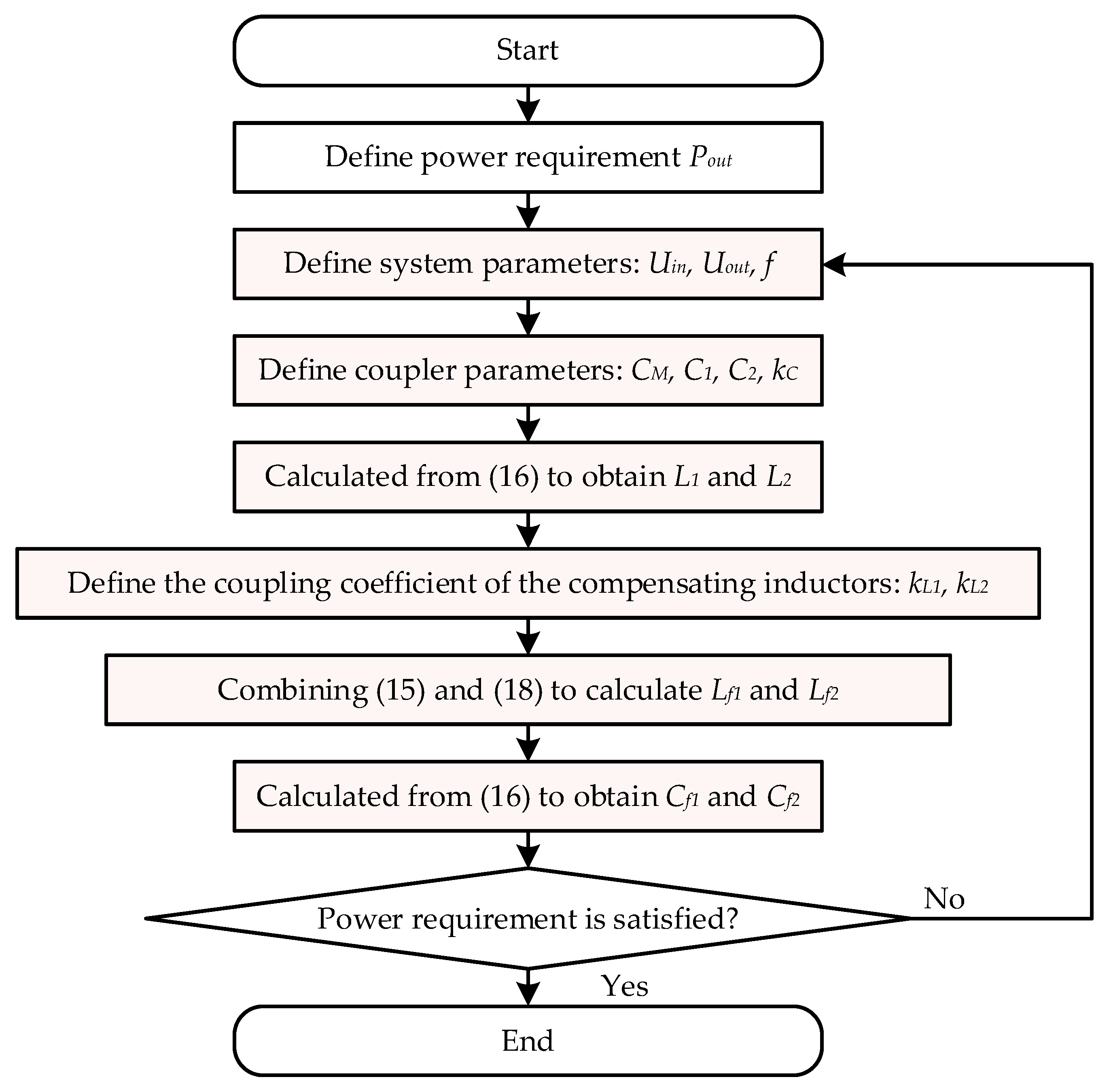
The design of the compensation network follows Figure 13. The target power is 3 kW. Considering the laboratory conditions, the primary-side power supply voltage and the secondary-side electronic load voltage are both set to 500 V. The inverter switching frequency is set to 1 MHz. The parameters related to the coupler, CM, C1, C2, and kC, are determined by the size of the coupler. The compensation network parameters to be determined are M1 and M2. According to (15), M1 and M2 are determined by kL1, kL2, Lf1, Lf2, L1, and L2. Here, kL1 and kL2 are specified as 0.4. L1 and L2 can be obtained based on the resonance condition given by (16). Next, combining (15) and (18) allows us to solve for Lf1 and Lf2. Finally, according to the resonance condition, Cf1 and Cf2 can be determined. It is worth noting that Cf1 should also be increased by 10% to achieve soft switching.
According to the analysis in Section 3, the coupler is divided into two cases for comparison and verification based on the distance from the coupler to the ship and the shore, namely, d1 = 10 mm and d1 = 50 mm. Therefore, the compensation network parameters corresponding to these two coupler sizes have been designed. The parameter selection is shown in Table 1.

5. Experimental Verification

5.1. Experimental Platform

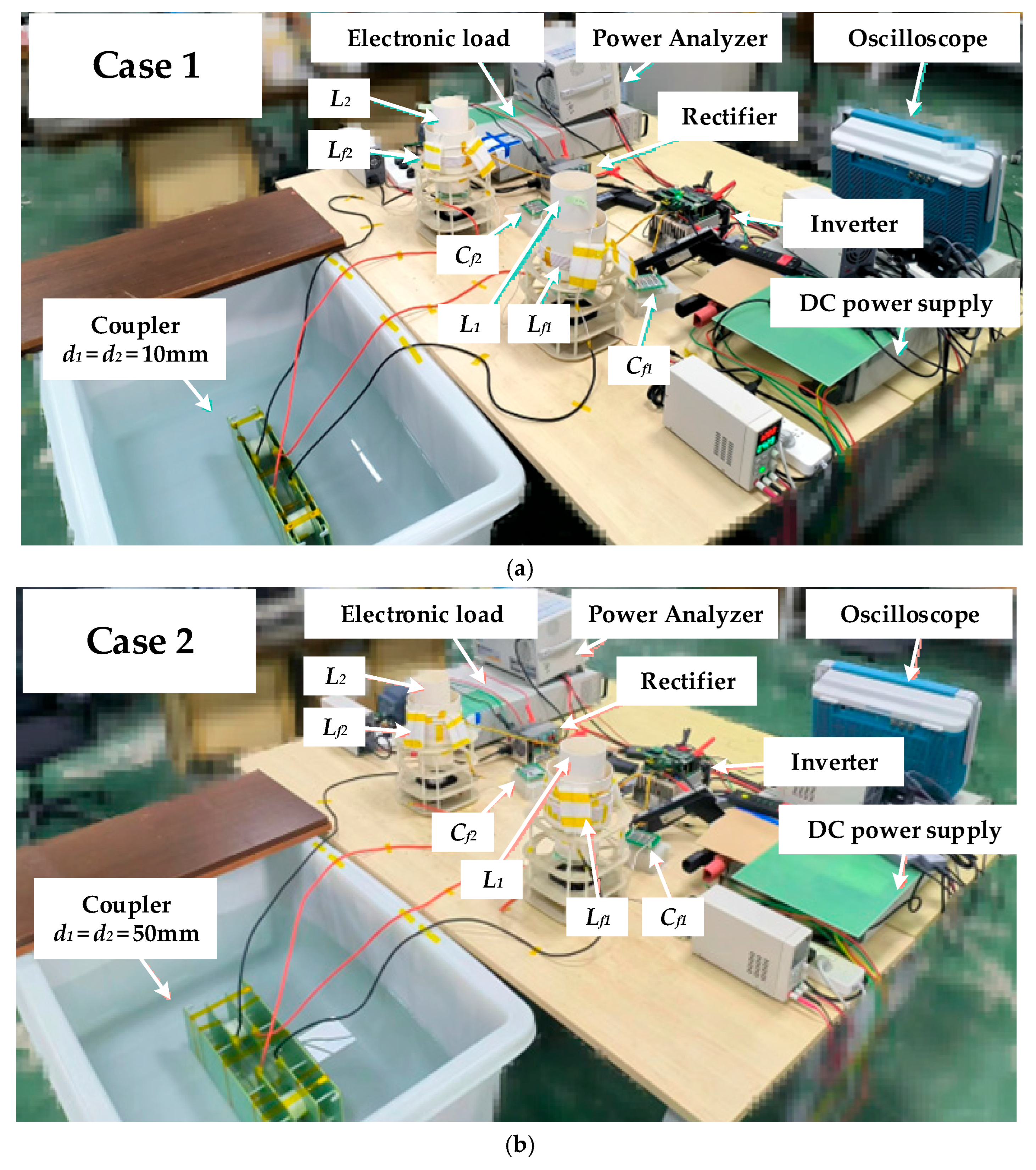
According to the previous design, experimental platforms for both operating conditions of the UCPT system were established. Figure 14a,b, respectively, show the experimental setups for case 1 and case 2. The dimensions of the coupler were configured according to Section 3. The power transfer plate was composed of four 2 mm thick aluminum plates. Two 530 mm × 230 mm × 2 mm aluminum plates were used to represent the boat and the shore, respectively. All aluminum plates were covered with 1 mm thick insulation. The transfer distance was d = 50 mm. In case 1, d1 = d2 = 10 mm. In case 2, d1 = d2 = 50 mm. The coupler was placed in fresh water with a relative permittivity of 81 and a conductivity of 0.0002 S/m. The water tank had dimensions of 1300 mm × 800 mm × 300 mm.
On the primary side of the UCPT system, a DC power supply model IT6018D-1500 was used as the input. The inverter converted the DC power into high-frequency AC power with a frequency of 1 MHz. The inverter adopted a full-bridge structure, with IMZ120R045M1 SiC-MOSFET switch devices with a high voltage resistance of 1200 V/40 A and overcurrent capability. The on-state resistance was 45 mΩ, with low high-frequency loss.
On the secondary side of the UCPT system, an electronic load model IT6000C-800 was used as the load. To simulate the battery of the boat, the electronic load operated in constant voltage (CV) mode. The rectifier converted the high-frequency AC power into DC power. The rectifier adopted a full-bridge structure, with FFSH40120ADN SiC-Diode main power devices with a high voltage resistance of 1200 V/40 A and overcurrent capability. Without reverse recovery, it is suitable for 1 MHz high-frequency rectification.
The compensation network had an M-M topology. Lf1 and L1 are resonant inductors on the primary side, wound with 0.04 mm × 4500 strands and 0.04 mm × 2000 strands of Litz wire, respectively. They have a coupling relationship, which is adjusted by a 3D-printed support plate and nylon screws. Cf1 is the resonant capacitor on the primary side, composed of multiple high-frequency film capacitors in series and parallel. Because the primary and secondary sides of the coupler are symmetrical, the compensation network is also designed to be symmetrical.
In addition, an oscilloscope model MSO46 was used to measure the voltage and current waveforms of the UCPT system, and a power analyzer model PA5000H was used to measure power and efficiency.

5.2. Experimental Results

To verify the optimization results, case 1 (suboptimal placement, low kC) and case 2 (optimized placement, high kC) were compared side by side.
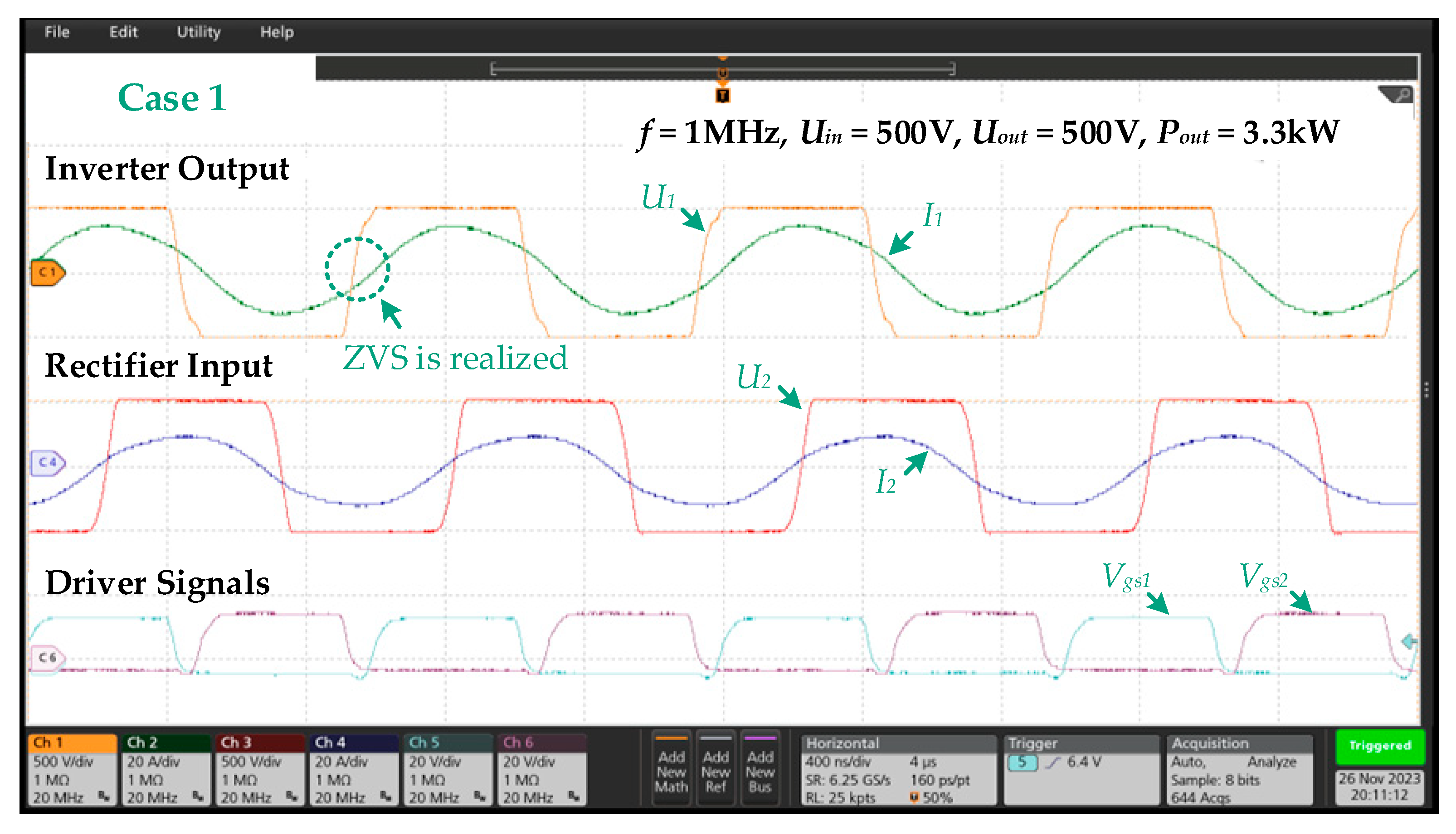
Firstly, the UCPT system under case 1 was tested. Figure 15 presents the waveforms of the inverter’s output voltage and current, rectifier’s input voltage and current, and the driving signals of the inverter’s power devices. The system operated under rated conditions with both Uin and Uout at 500 V. The output power was 3.3 kW. From Figure 15, the stable sinusoidal waveforms indicating the system was operating at resonance. Additionally, I1 slightly lagged behind U1, indicating that the inverter’s power devices were operating in the zero voltage switching (ZVS) state.
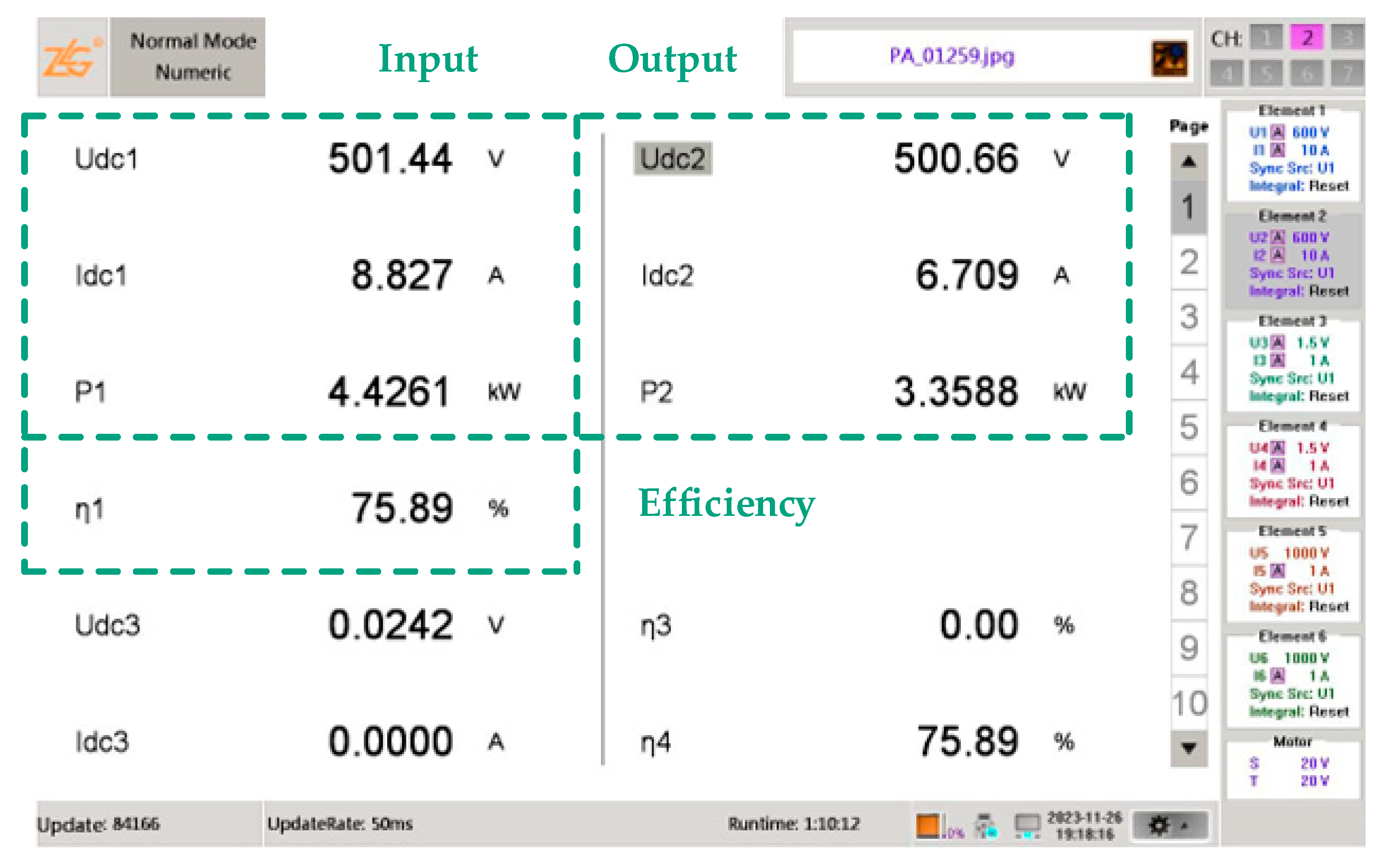
Figure 16 shows the efficiency value captured by the power analyzer as 75.89%. It is worth noting that this is the DC-DC efficiency under rated conditions.
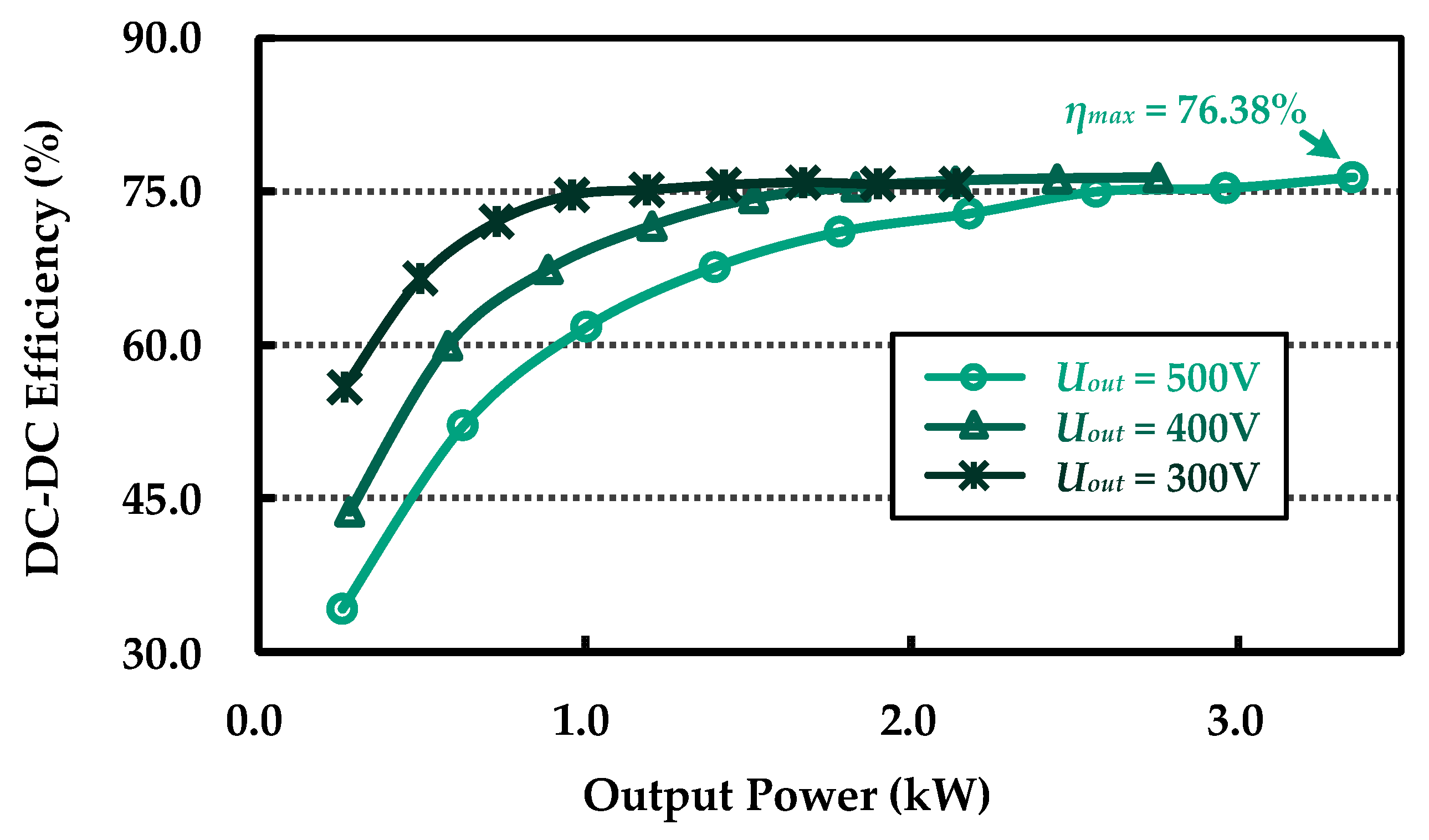
Subsequently, the electronic load voltage was set to 300 V, 400 V, and 500 V, respectively. The input DC power supply voltage was incremented from 100 V to 500 V in steps of 50 V. The efficiency vs. power curves under different load conditions were obtained, as shown in Figure 17. When Uout was 300 V, 400 V, and 500 V, the output power reached 2 kW, 2.7 kW, and 3.3 kW, respectively. In all three load conditions, an efficiency of over 75.9% was achieved. Additionally, it was observed that the efficiency increased as the load power increased. The observed trend is primarily attributable to the presence of fixed losses. Losses such as core losses in the compensation inductors, switching losses, gate drive power, and controller consumption remain relatively constant regardless of the power level. As the output power increases, these fixed losses constitute a smaller percentage of the total power processed, thereby leading to a higher overall system efficiency.
Next, the input DC power supply voltage was set to 300 V, 400 V, and 500 V, respectively. The load voltage was incremented from 100 V to 500 V in steps of 50 V. The load current vs. output power curves under different input voltages were obtained, as shown in Figure 18. It can be observed that the system exhibited a nearly invariant load current over a wide range of output power, demonstrating a robust constant-current output characteristic. Particularly, when the rated input voltage Uin was 500 V, the output power increased by 440%, while the output current decreased by only 11.6%.
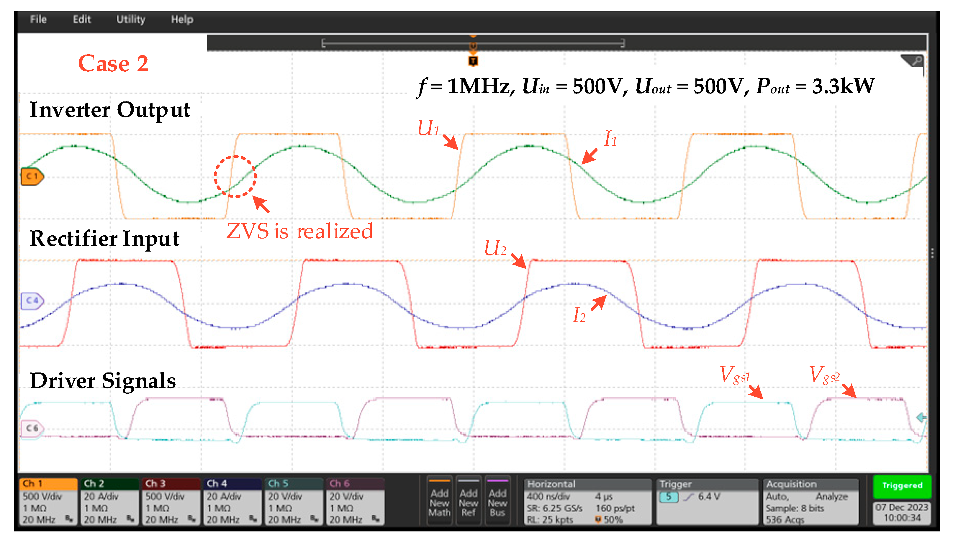
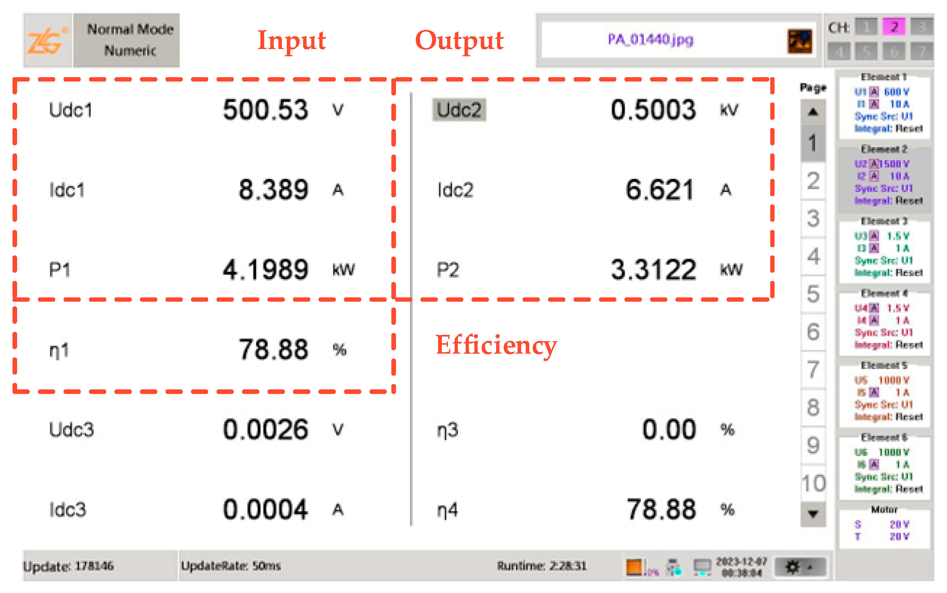
Next, the UCPT system under case 2 was tested. A rated output power of 3.3 kW was achieved with Uin = Uout = 500 V. The voltage and current waveforms under rated conditions are shown in Figure 19. The power and efficiency are shown in Figure 20. The waveforms demonstrate that the system achieved resonance and operated in the ZVS state. The DC-DC efficiency was measured to be 78.88%, a significant improvement compared to case 1. These results are consistent with the previous analysis.
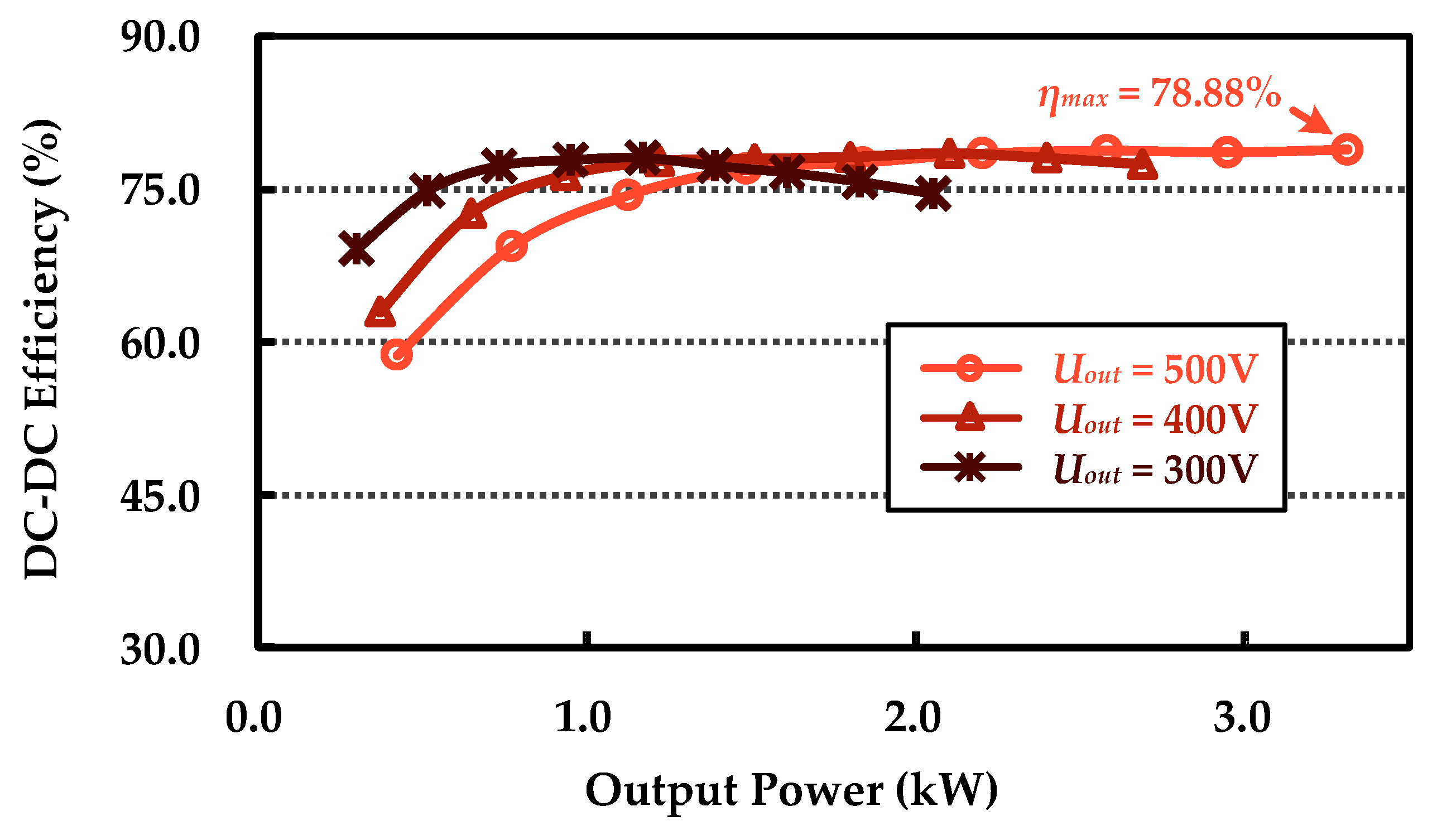
Subsequently, the electronic load voltage was set to 300 V, 400 V, and 500 V, respectively. The input DC power supply voltage was incremented from 100 V to 500 V in steps of 50 V. The efficiency vs. power curves under different load conditions were obtained, as shown in Figure 21. When Uout was 300 V, 400 V, and 500 V, the output power reached 2 kW, 2.7 kW, and 3.3 kW, respectively. Moreover, an efficiency of over 78% was achieved under all three load conditions.
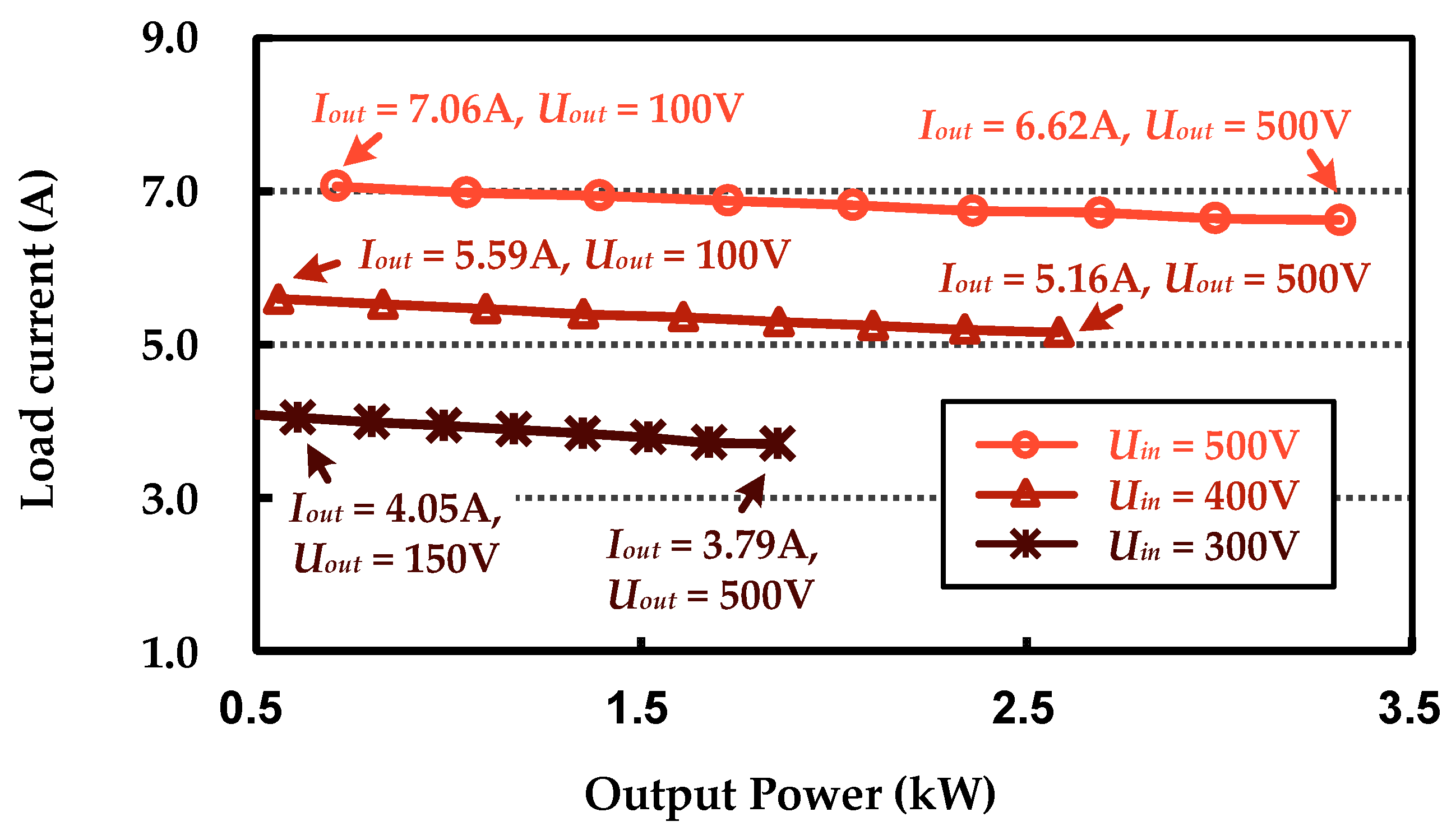
Next, the input DC power supply voltage was set to 300 V, 400 V, and 500 V, respectively. The load voltage was incremented from 100 V to 500 V in steps of 50 V. The load current vs. output power curves under different input voltages were obtained, as shown in Figure 22. It can be observed that the system exhibited a nearly invariant load current over a wide range of output power, demonstrating a robust constant-current output characteristic. Particularly, when the rated input voltage Uin was 500 V, the output power increased by 469%, while the output current decreased by only 6.2%. These test results demonstrate that the UCPT system under case 2 performed well across a wide range of operating conditions.
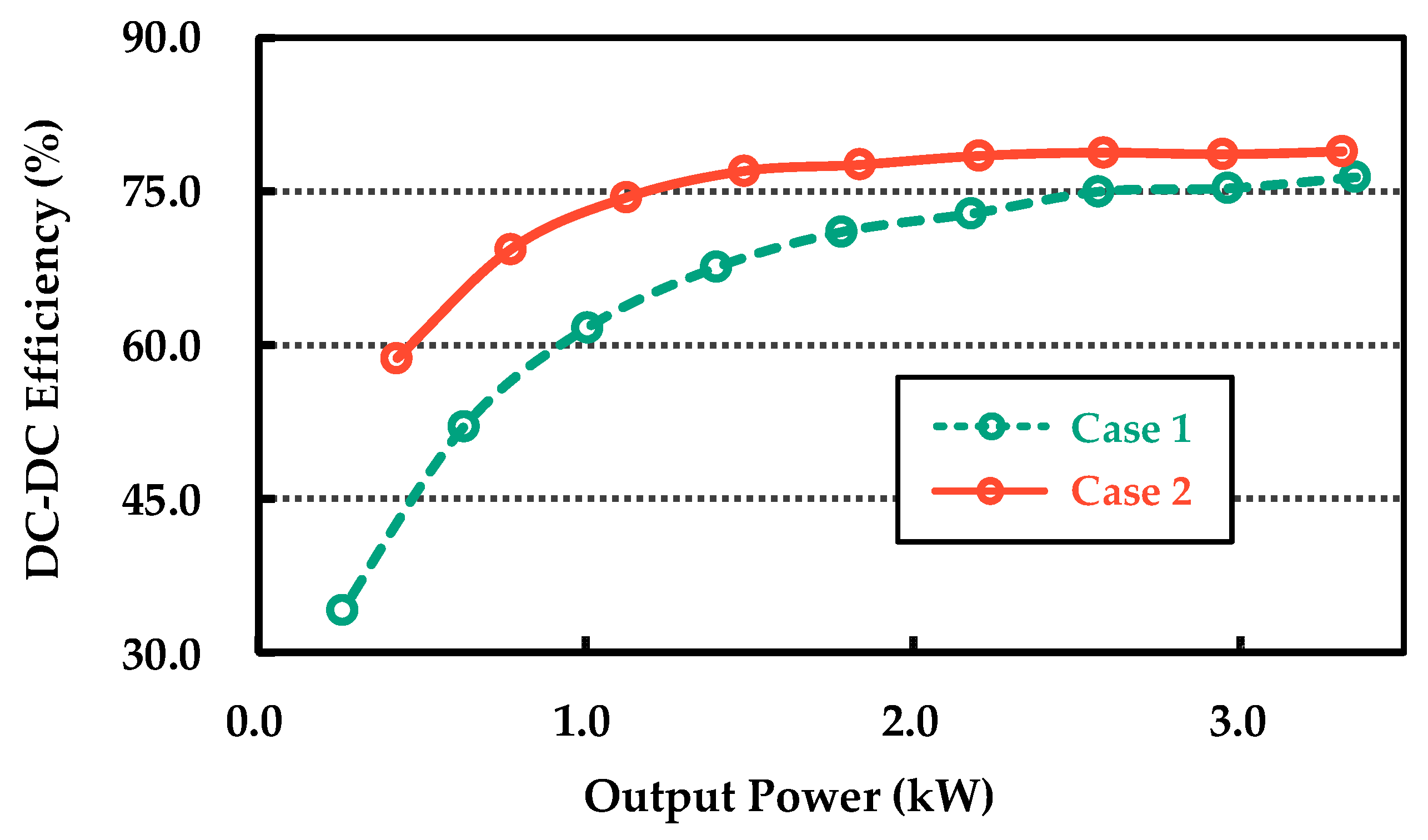
To better compare the performance of the UCPT system under case 1 and case 2, the efficiency vs. power curves under rated load conditions for both cases are simultaneously presented in Figure 23. It can be observed that the efficiency increases with increasing output power. However, the efficiency of case 2 is consistently higher than that of case 1. Furthermore, the load current vs. output power curves under rated input conditions for both cases are simultaneously shown in Figure 24. It can be seen that case 2 exhibits better constant current characteristics compared to case 1.
All experimental results demonstrate that case 2 is more suitable for high-power UCPT than case 1. This is because the coupling coefficient and mutual capacitance of the coupler in case 2 are larger. It also means that case 2 is less affected by the parasitic effects of the hull and shore, which is consistent with the theoretical analysis and the coupler optimization results. In practical applications, it is necessary to separate the UCPT coupler from the ship and shore by an appropriate mechanical structure or non-metallic buffer to achieve optimal performance.

6. Conclusions and Discussions

This research successfully designed and validated a UCPT system, with the aim of providing a reliable power supply for electric ships. At the core of this system lies an insulated capacitive coupler, which utilizes four metal plates and water as a medium to facilitate power transfer through coupled capacitance. However, considering the environmental factors, there are additional parasitic capacitances, apart from the coupled capacitance, that can affect the overall transfer efficiency. Therefore, these parasitic effects have been accounted for in the coupler model, which comprises fifteen admittances. Through finite element analysis, the research investigated the influence of varying distances between the coupler and the shore or ship on parameters such as equivalent self-capacitance, mutual capacitance, and coupling coefficient. The analysis revealed that, to achieve relatively high-efficiency UCPT, the transfer distance should be moderate, and the distances between the coupler and the shore or ship should not be excessively close. The target transfer distance for this research was set at 50 mm, and two different cases were compared and validated based on the respective distances between the coupler and the ship or shore.
To enable high-power transfer, a high-order compensation network employing M-M topology was adopted. A comparison with a low-order compensation network was made to illustrate the reasons behind the high-power transfer capabilities of the former. Experimental results demonstrated that both scenarios could achieve an output power of 3.3 kW in a freshwater environment. However, the condition with a greater distance between the coupler and the hull or shore demonstrated better performance (higher efficiency and better constant current characteristics). This is a direct result of the coupler optimization process guided by our theoretical and finite element analysis work. Consequently, this study showcases the ability of the UCPT system to maintain efficient transfer under diverse operational conditions. With its promising applications, this system offers an effective and sustainable energy solution for electric ships.
However, despite the positive outcomes observed in this study, it is important to acknowledge certain limitations and challenges associated with the UCPT system.
Firstly, enhancing the practicality of the entire system will be the primary goal of future work. According to the UCPT system structure shown in Figure 1, the plates are mounted on a mechanical arm. The mechanical arm has multiple degrees of freedom. When not charging, the transmitter side of the coupler is attached to the shore, and the receiver side is attached to the ship. During charging, the two sides of the coupler are aligned via the mechanical arm. This allows the coupler to maintain a certain distance from the shore and the ship, thereby reducing parasitic effects. This study conducted basic power transmission research under laboratory conditions, and further practical research will be conducted in the future. Secondly, in practical applications, the complexity of the underwater environment and its impact on system performance need to be further considered. Natural water bodies have higher and more variable conductivity. Pollution can also cause further changes in conductivity. The investigation of system performance in such environments, including the development of mitigation strategies for the resultant ohmic losses, is the critical and logical next step for our research. Thirdly, future research endeavors should focus on exploring additional technological advancements and optimizations to enhance the reliability and applicability of the UCPT system.

Author Contributions

Conceptualization, X.P. and E.R.; methodology, X.P.; validation, X.P., S.W. and E.R.; investigation, X.P. and H.Z.; writing—original draft preparation, X.P.; writing—review and editing, H.Z., G.F., S.W. and E.R.; funding acquisition, G.F. and E.R. All authors have read and agreed to the published version of the manuscript.

Funding

This research was funded by the National Key Research and Development Program of China (Grant No. 2022YFC3102800).

Data Availability Statement

The original contributions presented in this study are included in the article. Further inquiries can be directed to the corresponding authors.

Conflicts of Interest

The authors declare no conflicts of interest.

References

  1. Lee, G.-h.; You, Y.-m. Optimal Design for Torque Ripple Reduction in a Traction Motor for Electric Propulsion Vessels. Actuators 2025, 14, 314. [Google Scholar] [CrossRef]
  2. Liu, Y.; He, Y.; Liang, J.; Cao, Y.; Liu, Z.; Song, C.; Zhu, N. Progress on Research and Application of Energy and Power Systems for Inland Waterway Vessels: A Case Study of the Yangtze River in China. Energies 2025, 18, 4636. [Google Scholar] [CrossRef]
  3. Roberts, T.; Williams, I.; Preston, J.; Clarke, N.; Odum, M.; O’Gorman, S. Ports in a Storm: Port-City Environmental Challenges and Solutions. Sustainability 2023, 15, 9722. [Google Scholar] [CrossRef]
  4. Yu, X.; Xie, R.; Tu, Y.; Zhuang, Y.; Cheng, X.; Yin, F.; Zhang, Y. Compact Wireless Power Transfer with Enhanced Misalignment Tolerance via Independent Secondary PWM Control. IEEE Trans. Power Electron. 2025, 40, 11998–12002. [Google Scholar] [CrossRef]
  5. Liu, Y.; Sun, P.; Wu, X.; Wang, L.; Rong, E.; Li, Y.; Deng, Q. Multi-Parameter Identification Method for IPT System Based on Bipolar SPWM Technology. IEEE J. Emerg. Sel. Top. Power Electron. 2025, 13, 6753–6767. [Google Scholar] [CrossRef]
  6. Rahman, A.; Mizuno, T.; Takasaki, M.; Ishino, Y. An Equivalent Circuit Analysis and Suspension Characteristics of AC Magnetic Suspension Using Magnetic Resonant Coupling. Actuators 2020, 9, 52. [Google Scholar] [CrossRef]
  7. Cai, C.; Chen, T.; Ren, X.; Jiao, Y.; Liu, X.; Li, C.; Yu, J.; Wu, S. Modeling and Design of a Transcutaneous Resonant Capacitive Power Transfer Link for Biomedical Implants. IEEE Trans. Power Electron. 2024, 2, 3726–3737. [Google Scholar] [CrossRef]
  8. Liang, Y.; Sun, P.; Wu, X.; Wang, L.; Sun, J.; Rong, E.; Deng, Q. Input-Series Output-Series Multichannel IPT System for High-Voltage and High-Power Wireless Power Transfer. IEEE J. Emerg. Sel. Top. Power Electron. 2023, 11, 5509–5523. [Google Scholar] [CrossRef]
  9. Karimi, S.; Zadeh, M.; Suul, J.A. Shore Charging for Plug-In Battery-Powered Ships: Power System Architecture, Infrastructure, and Control. IEEE Electrif. Mag. 2020, 8, 47–61. [Google Scholar] [CrossRef]
  10. Mahdi, H.; Hoff, B.; Østrem, T. A Review of Power Converters for Ships Electrification. IEEE Trans. Power Electron. 2023, 38, 4680–4697. [Google Scholar]
  11. Qiao, K.; Rong, E.; Sun, P.; Zhang, X.; Sun, J. Design of LCC-P Constant Current Topology Parameters for AUV Wireless Power Transfer. Energies 2022, 15, 5249. [Google Scholar] [CrossRef]
  12. Sun, P.; Wu, X.; Cai, J.; Wang, X.; Zhang, X.; Liang, Y.; Xiong, Q.; Rong, E. Eddy Current Loss Analysis and Frequency Optimization Design of Double-Sided LCC-IPT System in Seawater Environment. Sci. China Technol. Sci. 2021, 65, 407–418. [Google Scholar] [CrossRef]
  13. Qiao, K.; Sun, P.; Rong, E.; Sun, J.; Zhou, H.; Wu, X. Anti-Misalignment and Light-Weight Magnetic Coupler with H-Shaped Receiver Structure for AUV Wireless Power Transfer. IET Power Electron. 2022, 15, 1843–1857. [Google Scholar] [CrossRef]
  14. Shafiq, Z.; Li, T.; Xia, J.; Li, S.; Yang, X.; Zhao, Y. Addressing EMI and EMF Challenges in EV Wireless Charging with the Alternating Voltage Phase Coil. Actuators 2024, 13, 324. [Google Scholar] [CrossRef]
  15. Li, Y.; Sun, P.; Liang, Y.; Wu, X.; Sun, J.; Rong, E.; Liu, Y.; Deng, Q. Research on Rectifier Fault Diagnosis and Self-Protecting for Inductive Power Transfer System with Constant-Current Output. IEEE Trans. Power Electron. 2025, 40, 3750–3769. [Google Scholar] [CrossRef]
  16. Zhou, X.; Wang, Y.; Yang, L. An LCC-LCC Compensated WPT System with Inherent CC-CV Transition Function for Battery Charging Applications. Wirel. Power Transf. 2024, 11, e002. [Google Scholar] [CrossRef]
  17. Xie, R.; Liu, Q.; Chen, Y.; Shi, J.; Yue, J.; Lin, G.; Chen, X.; Zhang, Y. A Simple Integrated Solution of Reconfigurable Wired and Wireless Vehicle-to-Vehicle (V2V) Charging System. Wirel. Power Transf. 2024, 11, e011. [Google Scholar] [CrossRef]
  18. Cai, J.; Sun, P.; Ji, K.; Wu, X.; Ji, H.; Wang, Y.; Rong, E. Constant-Voltage and Constant-Current Controls of the Inductive Power Transfer System for Electric Vehicles Based on Full-Bridge Synchronous Rectification. Electronics 2024, 13, 1686. [Google Scholar] [CrossRef]
  19. Zhou, W.; Chen, Z.; Zhang, Q.; Li, Z.; Huang, L.; Mai, R.; He, Z. Design and Analysis of CPT System with Wide-Range ZVS and Constant Current Charging Operation Using 6.78 MHz Class-E Power Amplifier. IEEE J. Emerg. Sel. Top. Power Electron. 2024, 12, 3211–3225. [Google Scholar] [CrossRef]
  20. Yang, G.; Sun, P.; Rong, E.; Zhang, X.; Wu, X.; Deng, Q. Universal Design Method of Load-Independent Constant Voltage and Constant Current Outputs for Capacitive Power Transfer System. IET Power Electron. 2025, 18, e70016. [Google Scholar] [CrossRef]
  21. Wang, Y.; Zhang, H.; Lu, F. Review, Analysis, and Design of Four Basic CPT Topologies and the Application of High-Order Compensation Networks. IEEE Trans. Power Electron. 2022, 37, 6181–6193. [Google Scholar] [CrossRef]
  22. Liang, C.; Liu, M.; Zhao, F.; Wang, D.; Wang, X.; Yuan, H.; Rong, M. A Multi-Cell SCC Capacitive Coupler with Strong Lateral, Longitudinal and Rotational Anti-Offset Performance. IEEE Trans. Power Electron. 2024, 4, 6230–6247. [Google Scholar]
  23. Lian, J.; Qu, X. Design of a Double-Sided LC Compensated Capacitive Power Transfer System with Capacitor Voltage Stress Optimization. IEEE Trans. Circuits Syst. II Express Briefs 2020, 67, 715–719. [Google Scholar] [CrossRef]
  24. Liu, Y.; Li, B.; Pan, L.; Yao, S.; Dong, Z.; Zhang, J.; Zhu, C.; Cui, S. Review on Development and Research of Underwater Capacitive Power Transfer. Energies 2024, 17, 6496. [Google Scholar] [CrossRef]
  25. Rong, E.; Sun, P.; Wu, X.; Cai, J.; Qiao, K.; Zhang, X.; Wang, L.; Liang, Y. Capacitive Wireless Power Transfer Coupler and Application Thereof. U.S. Patent Application No. 18/814,214, 1 July 2025. [Google Scholar]
  26. Rong, E.; Sun, P.; Zhang, X.; Yang, G.; Wu, X. 3.3 kW Underwater Capacitive Power Transfer System for Electric Ship Charging Application. In Proceedings of the 2023 IEEE International Conference on Power Science and Technology (ICPST), Kunming, China, 5–7 May 2023; pp. 1052–1057. [Google Scholar]
  27. Urano, M.; Takahashi, A. Study on Underwater Wireless Power Transfer via Electric Coupling. In Proceedings of the IEEE International Meeting on Future Electronics Devices, San Francisco, CA, USA, 3–7 December 2016; pp. 1–2. [Google Scholar]
  28. Urano, M.; Ata, K.; Takahashi, A. Study on Underwater Wireless Power Transfer via Electric Coupling with a Submerged Electrode. In Proceedings of the IEEE International Meeting on Future Electronics Devices, Kyoto, Japan, 29–30 June 2017; pp. 36–37. [Google Scholar]
  29. Tamura, M.; Naka, Y.; Murai, K.; Nakata, T. Design of a Capacitive Wireless Power Transfer System for Operation in Fresh Water. IEEE Trans. Microw. Theory Tech. 2018, 66, 5873–5884. [Google Scholar] [CrossRef]
  30. Tamura, M.; Naka, Y.; Murai, K. Design of Capacitive Coupler for Wireless Power Transfer under Fresh Water Focusing on kQ Product. In Proceedings of the MTTS International Microwave Symposium, Philadelphia, PA, USA, 10–15 June 2018; pp. 1257–1260. [Google Scholar]
  31. Bang, K.; Park, S. Design and Characteristics of Underwater Stacked Capacitive Power Transfer Coupler and Analysis of Propagation in Water Medium. Appl. Sci. 2025, 15, 1901. [Google Scholar] [CrossRef]
  32. Zhang, H.; Lu, F. Insulated Coupler Structure Design for the Long-Distance Freshwater Capacitive Power Transfer. IEEE Trans. Ind. Inform. 2020, 16, 5191–5201. [Google Scholar] [CrossRef]
  33. Li, H.; Li, G.; Jin, X.; Li, J.; Xu, G. A LC-CLL Compensated Capacitive Wireless Power Transfer System in Fresh Water. In Proceedings of the International Conference on Power and Energy Applications, Guangzhou, China, 18–20 November 2022; pp. 130–137. [Google Scholar]
  34. Zhang, X.; Lian, J. A Novel Coupler of Capacitive Power Transfer for Enhancing Underwater Power Transfer Characteristics. Electronics 2024, 13, 74. [Google Scholar] [CrossRef]
  35. Yang, L.; Tian, L.; Chen, X.; Bu, Z.; Xing, D.; Zhang, A.; Tong, X. Three-Phase High Power Underwater Capacitive Wireless Power Transfer System for Autonomous Underwater Vehicles. J. Mar. Sci. Eng. 2025, 13, 989. [Google Scholar] [CrossRef]
  36. Yang, G.; Sun, P.; Rong, E.; Zhang, X.; Wu, X.; Deng, Q.; Li, S. High-Power Capacitive Power Transfer System with Integrated Multi-Channel Coupler. IEEE Trans. Power Electron. 2025, in press. [CrossRef]
  37. Sinha, S.; Kumar, A.; Regensburger, B.; Afridi, K.K. A New Design Approach to Mitigating the Effect of Parasitics in Capacitive Wireless Power Transfer Systems for Electric Vehicle Charging. IEEE Trans. Transport. Electrific. 2019, 5, 1040–1059. [Google Scholar] [CrossRef]
  38. Regensburger, B.; Sinha, S.; Kumar, A.; Maji, S.; Afridi, K.K. High-Performance Multi-MHz Capacitive Wireless Power Transfer System for EV Charging Utilizing Interleaved-Foil Coupled Inductors. IEEE J. Emerg. Sel. Top. Power Electron. 2022, 10, 35–51. [Google Scholar] [CrossRef]
  39. Rong, E.; Sun, P.; Qiao, K.; Zhang, X.; Yang, G.; Wu, X. Six-Plate and Hybrid-Dielectric Capacitive Coupler for Underwater Wireless Power Transfer. IEEE Trans. Power Electron. 2024, 39, 2867–2881. [Google Scholar] [CrossRef]
  40. Zhang, H.; Lu, F.; Hofmann, H.; Liu, W.; Mi, C.C. A Four-Plate Compact Capacitive Coupler Design and LCL-Compensated Topology for Capacitive Power Transfer in Electric Vehicle Charging Application. IEEE Trans. Power Electron. 2016, 31, 8541–8551. [Google Scholar]
  41. Zhang, H.; Lu, F.; Hofmann, H.; Liu, W.; Mi, C.C. Six-Plate Capacitive Coupler to Reduce Electric Field Emission in Large Air-Gap Capacitive Power Transfer. IEEE Trans. Power Electron. 2018, 33, 665–675. [Google Scholar] [CrossRef]
  42. Wang, Y.; Zhang, H.; Cao, Y.; Lu, F. Remaining Opportunities in Capacitive Power Transfer Based on Duality with Inductive Power Transfer. IEEE Trans. Transp. Electrif. 2023, 9, 2902–2915. [Google Scholar] [CrossRef]
  43. Rong, E.; Sun, P.; Yang, G.; Xia, J.; Liu, Z.; Li, S. 5-kW, 96.5% Efficiency Capacitive Power Transfer System with a Five-Plate Coupler: Design and Optimization. IEEE Trans. Power Electron. 2025, 40, 2542–2555. [Google Scholar] [CrossRef]
  44. Mahdi, H.; Hoff, B.; Østrem, T. Optimal Solutions for Underwater Capacitive Power Transfer. Sensors 2021, 21, 8233. [Google Scholar] [CrossRef]
  45. Zhang, H.; Lu, F. Feasibility Study of the High-Power Underwater Capacitive Wireless Power Transfer for the Electric Ship Charging Application. In Proceedings of the 2019 IEEE Electric Ship Technologies Symposium (ESTS), Washington, DC, USA, 14–16 August 2019; pp. 231–235. [Google Scholar]
  46. Ji, H.; Sun, P.; Xiang, Y.; Hou, Y.; Zhang, X.; Rong, E. Groove Disk Capacitive Coupler for Wireless Rotor Excitation in Wound Field Synchronous Machines. In Proceedings of the 2025 IEEE International Conference on Industrial Technology, Wuhan, China, 26–28 March 2025; pp. 1–6. [Google Scholar]
  47. Liu, Z.; Zuo, C.; Li, S.; Lu, S.; Xia, J.; Zhao, Y.; Rong, E.; Li, T. A Large-Area Free-Positioning SCC-WPT System for Movable Receivers. IEEE Trans. Power Electron. 2025, 40, 8911–8916. [Google Scholar] [CrossRef]
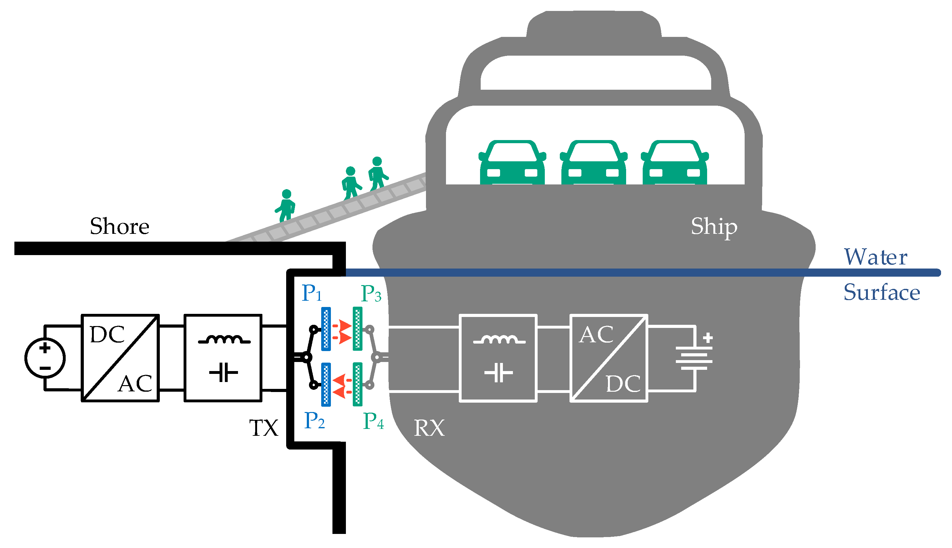
Figure 1. Underwater shore-to-ship capacitive power transfer system.
Actuators 14 00534 g001
Figure 2. Parasitic effects of couplers in real environments.
Actuators 14 00534 g002
Figure 3. Circuit modeling of the proposed coupler.
Actuators 14 00534 g003
Figure 4. Three-port equivalent model of the coupler.
Actuators 14 00534 g004
Figure 5. Two-port equivalent model of the coupler.
Actuators 14 00534 g005
Figure 6. Coupler 3D model and dimensions schematic.
Actuators 14 00534 g006
Figure 7. Coupler cross-section and dimensional schematic.
Actuators 14 00534 g007
Figure 8. Flowchart for acquiring coupler parameters.
Actuators 14 00534 g008
Figure 9. Coupler characteristics for variations in distance between the coupler and shore/ship.
Actuators 14 00534 g009
Figure 10. Coupler characteristics for variations in transfer distance.
Actuators 14 00534 g010
Figure 11. UCPT system with S-S compensation network.
Actuators 14 00534 g011
Figure 12. UCPT system with M-M compensation network.
Actuators 14 00534 g012
Figure 13. Parameterization flow of the compensation network.
Actuators 14 00534 g013
Figure 14. Experimental setup. (a) Case 1. (b) Case 2.
Actuators 14 00534 g014
Figure 15. Voltage and current waveforms for case 1.
Actuators 14 00534 g015
Figure 16. Screenshot of the power analyzer for case 1.
Actuators 14 00534 g016
Figure 17. Efficiency-power curve for case 1.
Actuators 14 00534 g017
Figure 18. Current-power curve for case 1.
Actuators 14 00534 g018
Figure 19. Voltage and current waveforms for case 2.
Actuators 14 00534 g019
Figure 20. Screenshot of the power analyzer for case 2.
Actuators 14 00534 g020
Figure 21. Efficiency-power curve for case 2.
Actuators 14 00534 g021
Figure 22. Current-power curve for case 2.
Actuators 14 00534 g022
Figure 23. Comparison of efficiency between case 1 and case 2.
Actuators 14 00534 g023
Figure 24. Comparison of constant current characteristics for case 1 and case 2.
Actuators 14 00534 g024
Table 1. Parameters of the UCPT Systems.
DesignatorParameterCase 1
(d1 = 10 mm)
Case 2
(d1 = 50 mm)
Cf1Source side capacitance2.53 nF1.71 nF
Cf2Load side capacitance2.53 nF1.71 nF
Lf1Source side inductance9.99 uF14.79 uH
Lf2Load side inductance9.99 uF14.79 uH
L1Primary side inductance45.63 uF62.65 uH
L2Secondary side inductance45.63 uF62.65 uH
kL1Inductive coupling coefficient0.40.4
kL2Inductive coupling coefficient0.40.4
C1Primary side capacitance587.01 pF458.85 pF
C2Secondary side capacitance587.01 pF458.85 pF
CMCoupling capacitance136.79 pF158.22 pF
kCCapacitive coupling coefficient0.230.34
Disclaimer/Publisher’s Note: The statements, opinions and data contained in all publications are solely those of the individual author(s) and contributor(s) and not of MDPI and/or the editor(s). MDPI and/or the editor(s) disclaim responsibility for any injury to people or property resulting from any ideas, methods, instructions or products referred to in the content.