1. Introduction
The formalization of engineering knowledge is a central tenet in the design of intelligent and resilient transportation systems. While substantial efforts have been devoted to improving physical modeling techniques, relatively little emphasis has been placed on the systematic formalization of safety-critical knowledge such as vehicle rollover risks, particularly in domain-specific contexts. Advanced Engineering Informatics emphasizes the computational formalization of engineering knowledge, integrating modeling, simulation, and intelligent systems to support safer and more efficient design and decision-making. This paper contributes to this domain by presenting a formalized modeling and decision-support framework for a complex, underexplored problem in road transport: the rollover risk of concrete mixer trucks.
Recent vehicle safety research has shifted toward intelligent control strategies for dynamic scenarios. RL-based controllers, for example, have shown superior efficiency and robustness in managing complex events like secondary collisions after rear-end crashes [
1]. Similarly, reachability-guided control strategies for extreme maneuvers in autonomous vehicles have formalized the boundaries of feasible control spaces and shown how intelligent systems can extend driver capabilities beyond conventional limits [
2]. These approaches signal a shift in safety research toward formal, predictive, and intelligent frameworks that can model not only physics-based responses but also decision-oriented dynamics.
However, the integration of such formal approaches into specialized heavy vehicle contexts, especially those with fluid–structure interactions, remains limited. Construction vehicles and other special-purpose trucks often operate in highly constrained and dynamically complex environments, where motion planning and stability prediction require context-aware constraint modeling [
3]. Moreover, in scenarios like rough-terrain navigation for electric vehicles, hierarchical control systems have been developed that formalize coupled vehicle–tire–terrain interactions in constrained predictive frameworks [
4]. These examples underscore the growing need for integrated simulation and decision logic to ensure operational safety in complex vehicle domains. Heavy trucks play a vital role in logistics and urban construction, yet their large mass, high center of gravity, and size make them especially prone to lateral instability—particularly during cornering or emergency maneuvers. This instability is primarily influenced by factors such as load distribution, suspension stiffness, center of gravity height, and wheel track geometry [
5]. These factors amplify the tendency of trucks to experience rollovers, posing a threat to safety and operational reliability [
6]. Among heavy vehicle accidents, rollovers are particularly severe due to their sudden onset and complex recovery demands. Compared to passenger cars, heavy trucks are inherently more susceptible to rollovers because of their structural and dynamic properties. However, previous studies have not translated high-fidelity fluid–structure interaction insights into sensor-level, real-time logic that formalizes rollover risk within a generalizable, system-level framework [
7]. This has made rollover stability analysis a central topic in vehicle safety research. Additionally, several studies [
8,
9] have confirmed that sloshing-induced forces significantly destabilize liquid-carrying vehicles like fuel tankers, increasing rollover risk.
Additional research has expanded the scope to include road geometry, suspension design, and steering dynamics, analyzing how roundabout geometry and pneumatic suspension affect roll stability using AMESim–TruckSim
® (2020.0) co-simulation. Shuichi et al. [
10] developed a 3-DOF model to assess how rollover motion affects heavy vehicles under real-world conditions. Meanwhile, Yubiao Zhang et al. [
11] proposed a generalized modeling technique for multi-axle vehicles, improving yaw and sideslip predictions by accounting for variations in cornering stiffness. Concrete mixer trucks, though structurally similar to tankers, present added complexity due to the non-Newtonian behavior of fresh concrete in rotating drums, leading to coupled dynamics that significantly affect lateral stability. Jiang et al. [
12] addressed this challenge by modeling the dynamic shift in the concrete’s centroid using CFD and validating the behavior with neural networks. Their findings confirmed that internal material motion significantly impacts stability and must be considered in safety modeling.
Beyond vehicle dynamics, other studies have focused on specific parameters affecting rollover thresholds. Tung et al. [
13,
14] investigated the relationship between speed, steering angle, and rollover likelihood in tractor-trailers, while Jin et al. [
14] introduced a new rollover index for multi-axle buses using a detailed 6-DOF model. Hung [
15] developed a 48-DOF simulation framework incorporating nonlinear tire models to define dynamic rollover thresholds in semi-trailers. Additional contributions have explored control-based solutions to improve stability [
16,
17,
18], and several have emphasized the need for better integration between fluid dynamics and vehicle dynamics in sloshing scenarios [
19,
20].
Despite existing studies, concrete mixers remain underexplored in rollover analysis. Most models oversimplify the rotating, partially filled drum, missing key dynamic interactions. System-level approaches that integrate high-fidelity simulations into real-time decision-making remain lacking.
Recent advancements in intelligent CFD frameworks have emphasized the integration of physical knowledge and simulation rules to automate and formalize the setup of flow problems in engineering systems [
21]. Such approaches can also support dynamic modeling in rotating tank systems like concrete truck mixers, where material behavior is complex and nonlinear. Similar integrative approaches have been explored in other industrial domains, where CFD-based modeling is combined with advanced control strategies. For example, in the context of zinc roasting processes, a recent study introduced a control framework using a CFD-based temperature field model and a Convolutional Q-Learning Network (CQLN) to adjust feed rate and position in real time, leading to better field uniformity and reduced error [
22].
To improve the fidelity of such dynamic simulations, recent studies have proposed enhanced vehicle modeling frameworks that incorporate powertrain limitations and component interaction using graph neural networks (GNNs). For instance, in the context of unmanned tracked vehicles, a dynamic model with a reduced feasible domain was shown to significantly enhance motion tracking accuracy and control efficiency by abstracting powertrain behavior through GNN-based representations [
23]. Such modeling principles can be extended to heavy-duty wheeled vehicles for more realistic analysis of traction and control dynamics under load.
To address these gaps, this study proposes a novel computational framework that combines CFD and vehicle dynamics simulation to assess and mitigate rollover risks in concrete truck mixers. The specific contributions and innovations of this work are as follows:
CFD-based modeling of fluid-tank interaction
Force coupling with multibody dynamics simulation
Quantification of rollover thresholds across maneuvers
Proposal of a cost-effective warning system
Broader safety and operational impact
Moreover, to accelerate the deployment of such safety-focused structural enhancements, recent developments in multi-objective optimization frameworks have demonstrated significant promise in improving both design efficiency and performance using limited simulation data [
24,
25]. These methods emphasize the importance of integrated optimization strategies in vehicle safety systems, enabling lightweight and robust structural modifications without extensive trial-and-error prototyping.
Similar to recent advancements in metamorphic vehicle design, where dynamic reconfiguration and multi-objective optimization improve operational stability [
26], the proposed warning system in this study aims to enhance rollover safety in heavy trucks through minimal intervention and without additional hardware.
In line with the growing emphasis on integrating advanced computational approaches into intelligent transportation systems, recent research has highlighted the transformative potential of large-scale models in enhancing perception, reasoning, and real-time decision-making across autonomous vehicle applications [
27]. These developments underscore the necessity of embedding lightweight yet scalable computational strategies, such as the one proposed in this study, into safety-critical domains like heavy vehicle operations.
Earlier versions of this study were presented in [
28,
29], where initial concepts were introduced. In the present work, these concepts are further developed into a more detailed and formalized framework, integrating CFD–multibody coupling with a structured rollover-warning algorithm and including a comparative evaluation against existing safety systems.
2. Methodology
2.1. Framework Overview
The present study introduces a unified simulation-driven safety framework that integrates computational fluid dynamics (CFD), multibody vehicle dynamics, and rollover-warning logic into a single modeling process. The framework aims to capture the complex coupling between the fluid motion inside a rotating drum and the vehicle’s dynamic stability during cornering maneuvers.
To provide an overview of the proposed methodology, the main steps of the integrated framework are summarized below. As shown in
Figure 1, the framework consists of three main stages:
- 1.
CFD-Based Sloshing Simulation:
The transient CFD model of the partially filled mixer drum is used to calculate the time-dependent lateral and vertical forces, as well as the roll and pitch moments, generated by the motion of the concrete during rotation. These outputs represent the fluid–structure interaction effects that influence vehicle stability.
- 2.
Multibody Dynamics Coupling:
The dynamic loads obtained from the CFD model are introduced into the TruckSim® (2020.0) multibody simulation to assess the vehicle’s global behavior under different driving conditions. The simulation yields key parameters such as lateral acceleration, roll angle, and load transfer, enabling the identification of rollover onset conditions.
- 3.
Rollover-Warning Algorithm:
Based on the critical thresholds determined from the coupled simulations, a warning logic is implemented to evaluate the risk of rollover in real time. The system compares the instantaneous vehicle speed, steering angle, and lateral acceleration against the pre-defined limits derived from simulation results.
This structured integration provides a general methodology for linking detailed fluid simulations with vehicle stability assessment and control design. While the framework is demonstrated here for a concrete truck mixer, it is formulated to be adaptable to other heavy-duty vehicles with partially filled tanks or complex load dynamics.
2.2. Tank Modeling and Setup
This study introduces a numerical framework that uses Computational Fluid Dynamics (CFD) and multibody vehicle dynamics simulation to assess the rollover behavior of concrete truck mixers. The process consists of four main phases: tank modeling and characterization, CFD simulation and force extraction, vehicle dynamics simulation in TruckSim® (2020.0), and preparation for safety system development.
The geometry of a typical concrete mixer tank was designed using CAD software (SolidWorks 2023 SP3.0), based on industry-standard volumes ranging from 6 to 15 m
3. In this study, the selected tank has a usable volume of 8300 L, and simulations assume a 68% fill level [
30], reflecting common operational conditions. The tank rotates around its longitudinal axis at 3 RPM, which is standard during concrete discharge and routine mobility (between 2 and 6 RPM for different categories of concrete truck mixers).
The tank’s internal blades induce continuous mixing and lateral mass shifts, affecting the center of gravity (CoG) of the tank and vehicle. Accurate CoG calculation was essential for applying external forces in the vehicle dynamics model [
31].
2.3. CFD Simulation in ANSYS Fluent
To capture the dynamic behavior of the concrete inside the rotating tank, a transient CFD simulation was carried out using the Volume of Fluid (VOF) model in ANSYS Fluent (2023 R2). This model tracks the interface between two immiscible phases, air and concrete, with concrete treated as a non-Newtonian flowable mixture (viscosity: 20 N·s/m
2, density: 2400 kg/m
3) [
32,
33].
Lateral accelerations from 0 g to 0.6 g simulated turning conditions, with tank rotation modeled via frame motion. A transient pressure-based solver and standard k–ε turbulence model captured the time-dependent sloshing and turbulence effects.
2.4. Force and Moment Extraction
From each CFD simulation, the resulting lateral force, vertical force, and moments around the longitudinal and vertical axes were extracted. These dynamic loads represent the effect of both lateral acceleration and tank rotation on the internal concrete. The forces were applied at the tank’s center of mass.
These values were then used as external force inputs in the vehicle dynamics model to replicate real-world handling behavior under loading.
2.5. Vehicle Dynamics Simulation in TruckSim® (2020.0)
A detailed TruckSim® (2020.0) model was developed using the vehicle’s mass, suspension, and tire data. CFD-derived loads were applied at the CoG. Rollover risk was assessed using two standard driving maneuvers:
ISO steady-state cornering at radii from 10–100 m, for both loaded and unloaded conditions.
Step steering test, using steering angle inputs of 180°, 250°, 360°, 750°, and 970°, applied in single-step and two-step formats.
Each test was run iteratively at increasing speeds until tire lift-off was observed, indicating the rollover threshold. These thresholds were recorded for later use in validation and safety system logic.
2.6. Data Preparation for Safety System Design
The speed thresholds, lateral acceleration data, and other outputs from the simulations were compiled to support the development of a driver-assistance warning system. Only variables measurable with standard truck sensors were considered: vehicle speed, steering angle, tank load level, and tank rotation speed.
3. CFD Simulation and Results
A computational fluid dynamics (CFD) model was developed to evaluate the dynamic forces acting within a partially filled, rotating concrete mixer tank under lateral acceleration. These forces, generated by the movement of fresh concrete during truck maneuvers, directly influence rollover behavior. The simulation process includes the preparation of tank geometry, meshing, configuration of the transient solver in ANSYS Fluent (2023 R2), and post-processing of force and torque outputs for integration with vehicle dynamics analysis.
3.1. Tank Geometry and Internal Volume Setup
The truck mixer tank geometry was designed using SolidWorks CAD software (2023 SP3.0) to represent a standard drum configuration equipped with internal mixing blades. The total usable volume of the tank is 8300 L. For this study, a 68% fill level was used, corresponding to 5644 L of concrete [
30]. The blade geometry was modeled to realistically capture the continuous mixing and lateral shifting of the viscous concrete during drum rotation.
The tank was set to rotate clockwise about the longitudinal axis at a constant speed of 3 revolutions per minute (RPM), reflecting typical operating conditions during urban delivery. Only the internal fluid volume was considered in the CFD domain, as the focus was on simulating the air-concrete interface and the associated sloshing behavior under maneuvering conditions.
Figure 2 illustrates the two key reference points used throughout this study. Point B marks the center of mass (CoM) of the loaded tank, while Point A represents the center of mass of the complete truck mixer with the loaded tank. These points serve as the basis for applying the CFD-derived forces in the multibody vehicle dynamics model in TruckSim
® (2020.0) software. The figure also includes a coordinate system, providing a visual reference for understanding the spatial orientation and relationships between points A and B in the context of this study, while
Figure 3 shows prepared tank geometry and internal concrete distribution (68% fill).
In this study, lateral motion of the drum CoM was not prescribed; sloshing-induced lateral effects entered the TruckSim® (2020.0) model through CFD-derived force components applied at Point B, while the CoM locations (A and B) remained fixed for the symmetric fill case.
Figure 2.
Truck mixer’s center of mass. Point A: Loaded vehicle CoM; Point B: tank CoM after loading.
Figure 2.
Truck mixer’s center of mass. Point A: Loaded vehicle CoM; Point B: tank CoM after loading.
Figure 3.
Prepared tank geometry and internal concrete distribution (68% fill).
Figure 3.
Prepared tank geometry and internal concrete distribution (68% fill).
3.2. Mesh Generation and Independence Study
The CFD mesh was generated using ANSYS Meshing (2023 R2), chosen for its compatibility with Fluent and ability to handle the complex geometry of the rotating tank. The mesh was refined in areas near the internal blades and walls where velocity gradients are expected to be high. Care was taken to maintain mesh quality and minimize numerical diffusion.
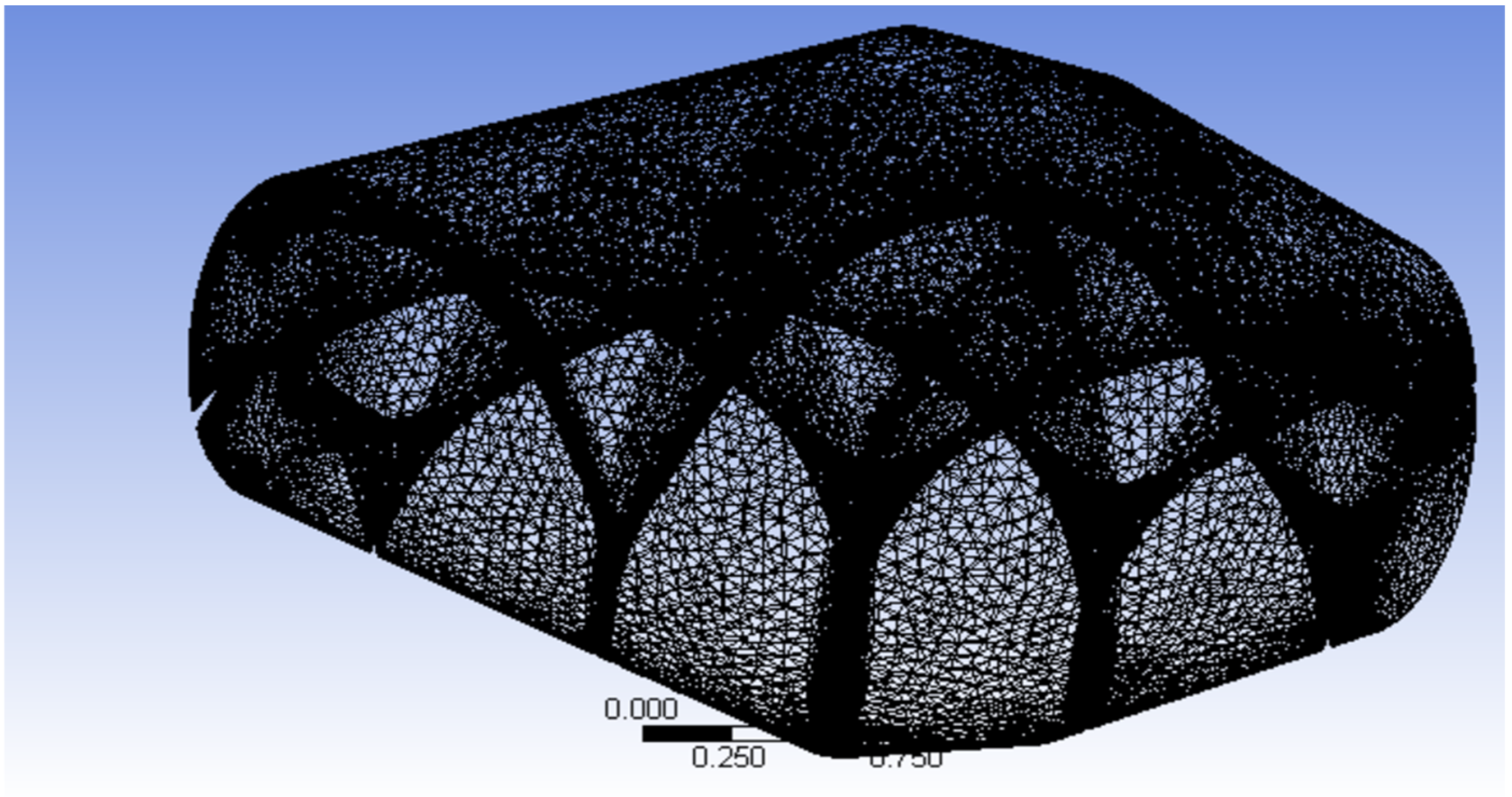
A mesh independence study was performed to confirm that the selected mesh provided accurate results without excessive computational cost. Three mesh densities were compared, and the final mesh was chosen based on force output convergence with less than 3% variation from the finer configuration. The quality indicators for the selected mesh are shown in
Table 1, while the final mash is showed in
Figure 4.
3.3. Solver Settings and Boundary Conditions
The simulations were performed in ANSYS Fluent (2023 R2) using a pressure-based, transient solver to capture time-dependent fluid behavior within the rotating tank. The tank was modeled as a two-phase system consisting of concrete and air, using the Volume of Fluid (VOF) method to accurately track the interface between the two immiscible fluids. Concrete was defined as a non-Newtonian flowable mixture, with a viscosity of 20 N·s/m
2 and a density of 2400 kg/m
3, based on established literature values [
32,
34].
To simulate operational conditions, the tank was rotated at 3 revolutions per minute (RPM) using a frame motion method about the longitudinal axis. Lateral acceleration was applied to the system in increments of 0.05 g, ranging from 0 g to 0.6 g, which corresponds to real-world accelerations encountered by concrete mixers during turning and evasive maneuvers.
Turbulence effects were modeled using the standard k–ε turbulence model, which provides a balance between computational cost and accuracy for internal, rotating flows. The gravitational field was enabled in all three directions to simulate realistic vertical and lateral loads on the tank contents. A time step of 0.01 s was selected to resolve the fluid motion and capture transient effects accurately.
All simulations were run until convergence criteria were satisfied and results stabilized. Forces and torques acting on the tank walls were extracted as outputs for each lateral acceleration level.
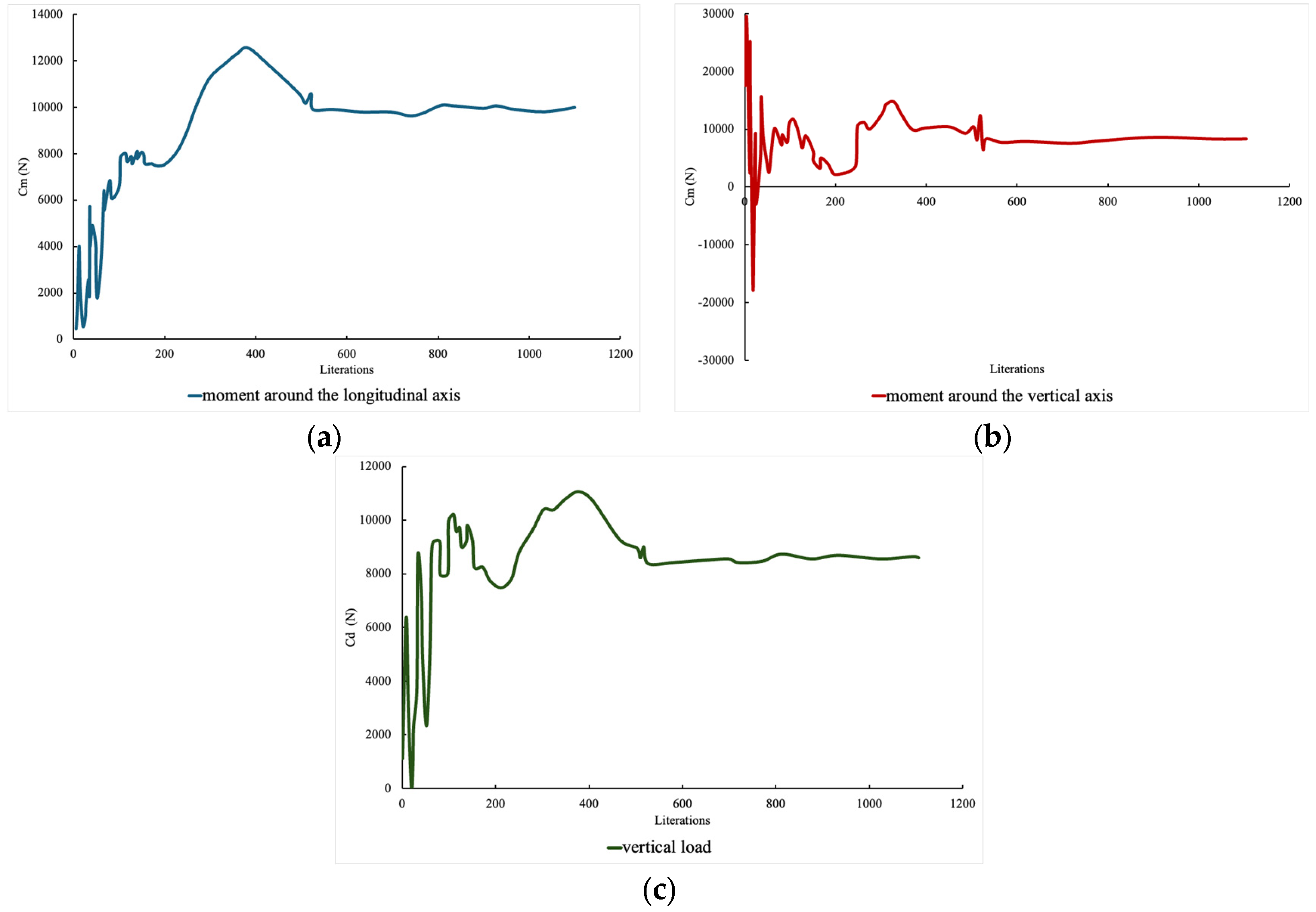
In addition to mesh quality control, convergence checks were performed based on the evolution of the moments around the longitudinal and lateral axes, as well as the vertical reaction force, as shown in
Figure 5.
3.4. Simulation Outputs: Forces and Moments
The primary outputs from the CFD simulations were the forces and torques exerted on the internal tank walls by the moving concrete. These quantities directly reflect the fluid’s response to the combination of tank rotation and externally applied lateral acceleration.
The following parameters were extracted:
Lateral Force (Fy): Resulting from fluid shift during lateral acceleration.
Vertical Force (Fz): Influenced by both gravitational load and vertical motion of the fluid.
Torque around Longitudinal Axis (Mx: Arising from asymmetric internal mass distribution during drum rotation.
Torque around Vertical Axis (Mz: Caused by the interaction between rotation and turning forces.
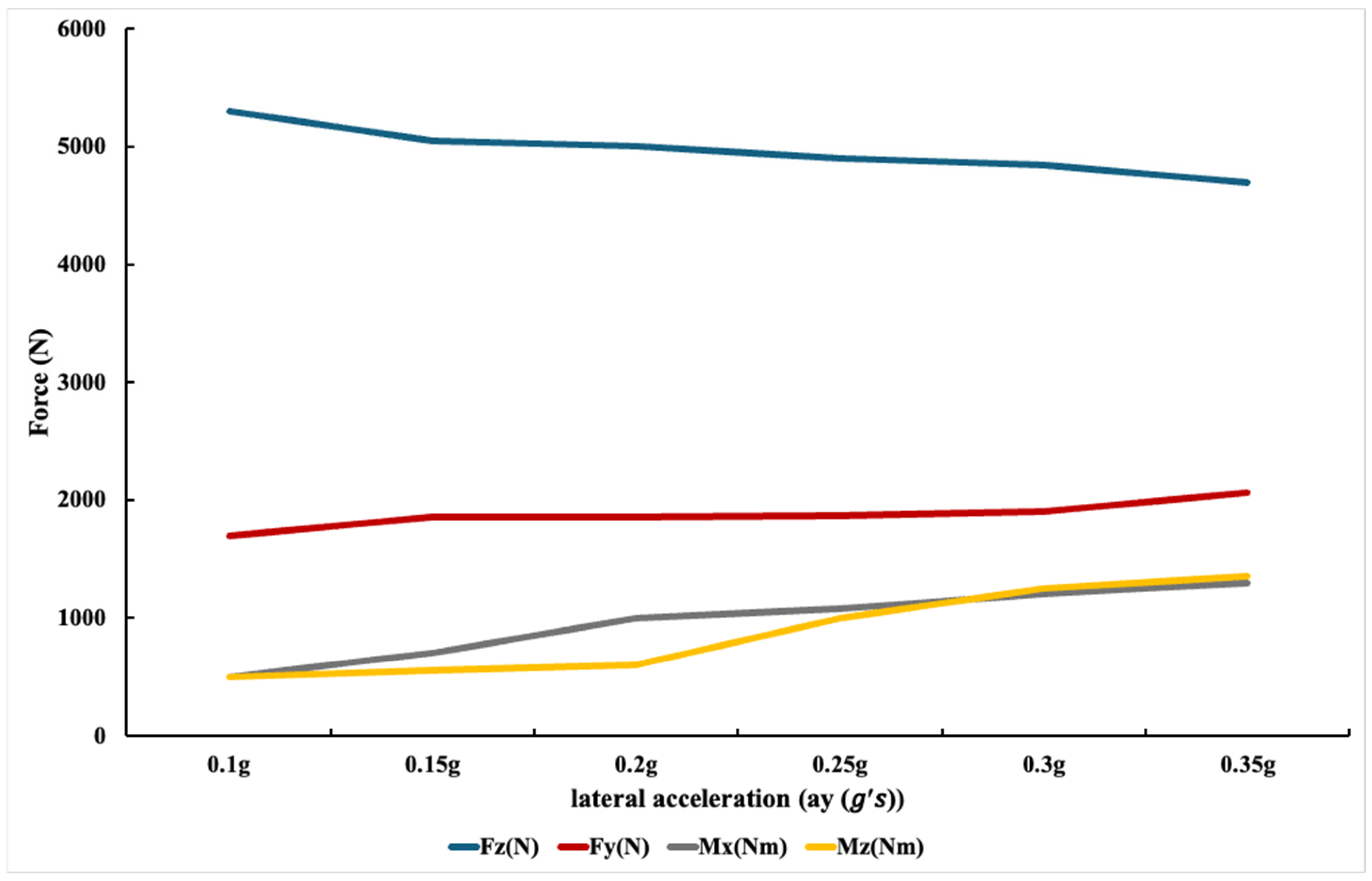
These outputs were computed for each lateral acceleration level (0 g to 0.6 g). The results showed approximately linear behavior of all parameters within the tested range, confirming stable fluid response under the defined conditions. This linearity simplifies the translation of CFD data into external inputs for the vehicle dynamics model in TruckSim® (2020.0).
An important observation was that vertical force began to decline more noticeably beyond 0.35 g, indicating a reduction in vertical support that could contribute to tire lift-off in dynamic situations. This threshold was later validated against vehicle dynamics simulations and used to support rollover risk prediction.
Figure 6 illustrates the variation in lateral force, vertical force, and torques as a function of lateral acceleration.
3.5. Convergence and Model Stability
Each CFD simulation was monitored for convergence by tracking the residuals of continuity, momentum, volume fraction, and turbulence parameters. Convergence was typically achieved within 1000–1200 iterations, with all residuals falling below 10−3, and no signs of divergence or oscillatory instability observed in the results.
In addition to residuals, simulation stability was assessed by monitoring force and torque fluctuations over time. After an initial transient phase, all force values settled into stable profiles for each lateral acceleration level, allowing for consistent extraction of averaged outputs over the final simulation window.
The selected mesh configuration contributed to this stability, as evidenced by the mesh independence study and good mesh quality indicators. These factors confirmed that the simulations were numerically reliable and provided trustworthy inputs for the next modeling phase.
3.6. Interpretation and CFD-to-TruckSim® (2020.0) Transition
The outputs of the CFD analysis, lateral forces, vertical forces, and rotational moments, represent the fluid-induced loads acting on the tank during vehicle maneuvers. These dynamic effects, particularly the lateral and vertical forces, play a critical role in the onset of rollover by shifting the effective load distribution and influencing tire-ground interaction. The relatively linear relationship observed between the applied lateral acceleration and the resulting forces supports the assumption of predictable, scalable dynamic behavior within the operational range (0–0.6 g). This characteristic simplifies integration with the vehicle dynamics simulation tool, where these loads are used as external inputs.
The extracted values were applied to the truck model in TruckSim® (2020.0) at the tank’s center of mass (Point B) to replicate the real-world influence of sloshing and rotation on vehicle handling. This coupling enables the simulation of full-vehicle maneuvers, such as steady-state cornering and step steering, under realistic, fluid-loaded conditions.
This combined approach bridges detailed internal fluid dynamics with system-level vehicle response, forming the basis for analyzing rollover thresholds and designing a practical driver alert system later in this study.
4. Rollover Model and Theoretical Analysis
As previously discussed, an elevated center of gravity (CoG) significantly increases a vehicle’s susceptibility to rollover. Other geometric and mechanical parameters, such as wheel track width and suspension stiffness, also play critical roles, the latter affecting the roll angle and overall vehicle stability. To fully understand the rollover mechanism in this context, it is necessary to examine how these parameters interact and influence critical rollover conditions.
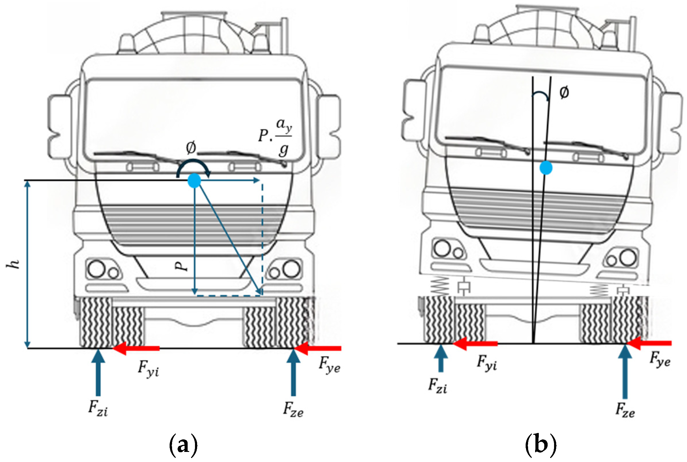
Figure 7a presents a simplified static rollover model that visually demonstrates the effects of CoG height, track width, and applied lateral acceleration on vehicle stability. This schematic helps illustrate the balance of forces and moments at the threshold of rollover. The specific vehicle parameters used in the model are listed in
Table 2, corresponding to the configuration depicted in the figure.
As will be demonstrated later in this study, the roll angle (∅) can be accurately estimated using several measurable parameters available from standard vehicle sensors. This insight forms the basis for developing a driver assistance system capable of continuously monitoring rollover risk. By incorporating the estimated roll angle alongside other key data, the system can provide timely warnings to enhance vehicle safety and help prevent rollover incidents.
By examining the equilibrium condition involving the primary rolling moment (
), the reaction moment (
) and the center of mass displacement moment (Ph∅), Equation (1) is obtained. From this expression, the rollover limit can be identified as specified in Equation (2) It should be noted that this is a simplified model, developed to identify the main variables involved in the rollover process. Based on this framework, specific conditions will be simulated, with particular attention given to the behavior and interaction of these key variables.
Figure 7b, illustrates the rollover condition states that when no force on one wheel
and the other supports all the weight
. So, clearing:
5. TruckSim® (2020.0)-Based Rollover Analysis and Critical Speed Evaluation
Following the CFD-based force and moment extraction, the next phase involves applying these results to a multibody vehicle model in TruckSim® (2020.0) to evaluate the rollover behavior of the concrete truck mixer under realistic driving conditions. The extracted lateral and vertical forces, along with torque values, were introduced as external inputs at the tank’s center of mass. Key vehicle parameters, such as total weight, suspension properties, and the location of the center of gravity, were also defined to ensure accurate simulation.
Two categories of maneuvers were simulated to assess stability and identify the maximum safe speed before rollover occurs: the ISO steady-state cornering test and the step steering test. Both were performed for loaded and unloaded conditions across a range of turning radii and steering angles. Tire lift-off was used as the primary indicator of rollover onset, and tire normal forces were monitored throughout to validate the dynamic behavior.
5.1. Multibody Model Configuration and Static Load Distribution
The truck mixer was modeled in TruckSim® (2020.0) as a three-axle heavy-duty vehicle, composed of one front steering axle and two rear drive axles connected through a tandem suspension system. This configuration reflects a typical commercial 8 m3 concrete mixer chassis.
The vehicle geometry used in the simulation included a 4.25 m wheelbase between the first and second axles and 1.35 m between the second and third axles, with a total track width of 2.05 m. The curb mass of the truck was 17,500 kg, and the payload mass corresponding to a 68% drum fill (≈8.3 m3 × 0.68 × 2400 kg/m3 = 13,600 kg) yielded a total loaded mass of approximately 31,100 kg.
Each suspension was represented by nonlinear spring–damper elements reproducing the roll and pitch stiffness characteristics of heavy-duty leaf-spring assemblies. The roll stiffness values were set to 200 kN·m/rad for the front axle and 340 kN·m/rad for the tandem rear axles. The tires were modeled using the TruckSim® (2020.0) heavy-truck “Magic-Formula” parameters (load range 20–60 kN, cornering stiffness 65 kN/rad).
Static equilibrium was solved prior to all dynamic maneuvers, and the resulting static normal loads on each tire were extracted directly from the TruckSim® (2020.0) output. These values are summarized below for both mass conditions.
These correspond to axle loads of 84 kN (front) and 210 kN (rear tandem) under the loaded condition, consistent with manufacturer specifications for vehicles of this class.
The same multibody model and mass distribution were used throughout all simulations, ensuring that differences in rollover thresholds arose exclusively from maneuver type, speed, and fluid–structure interactions derived from the CFD analysis.
It should be mentioned that all simulations were performed on a flat road surface (zero cross-slope) in accordance with ISO 14792 [
35] specifications for steady-state cornering and step-steering tests. This configuration was selected to isolate the effects of lateral acceleration, steering input, and load distribution on rollover behavior, without introducing additional stabilizing or destabilizing influences from road banking.
5.2. Modeling in TruckSim® (2020.0) Software
Following the simulation of the tank and fluid dynamics, and the extraction of the resulting forces from fluid motion, these forces were applied as external inputs into the TruckSim® (2020.0) software. The forces and moments were introduced at the tank’s center of mass, with additional vehicle parameters, such as total weight and center of gravity location, accurately defined. This setup enabled a series of targeted simulations to evaluate the truck’s dynamic response and rollover tendencies.
To assess the vehicle’s handling and stability characteristics, three types of tests were conducted, as described below:
This test was carried out for both loaded and unloaded truck conditions, using turning radii of 10, 20, 30, 40, 50, and 100 m. The results from these simulations are systematically compared and shown later. The ISO steady-state cornering test is a widely accepted standard for assessing vehicle handling performance and serves as the primary evaluation method in this study. Its main objective is to evaluate the steady-state turning behavior of heavy-duty vehicles during sustained left and right turns [
35,
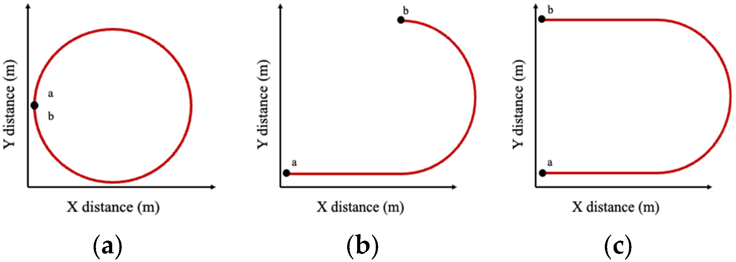
36]. The path followed during this maneuver is illustrated in
Figure 10a.
- 2.
Step Steering Test with Single Steering Input:
A series of single-step steering maneuvers were applied to the loaded truck mixer with steering angles of 180°, 250°, 360°, 750°, and 970°. This test simulates sudden steering events and evaluates vehicle stability under abrupt directional changes. The corresponding maneuver path is shown in
Figure 10b.
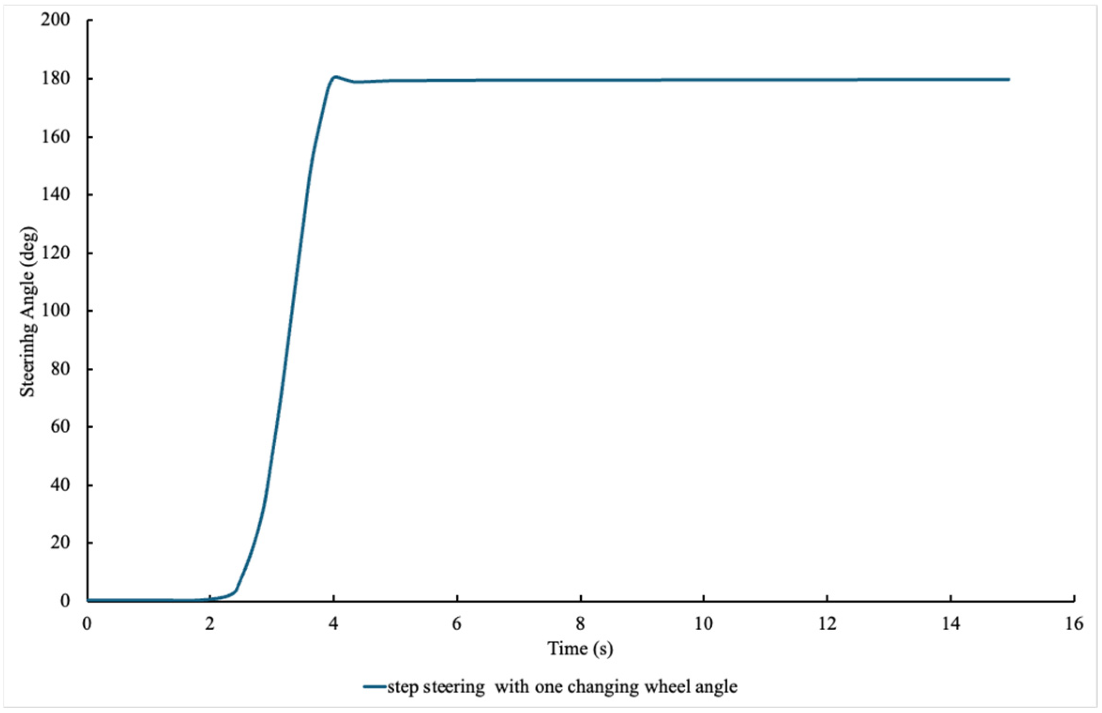
To better illustrate the steering input used in the simulations,
Figure 8 presents the steering-angle command for the one-step maneuver, which consists of a single rapid increase in wheel angle that is then held constant for the remainder of the test.
- 3.
Step Steering Test with Double Steering Input:
In this test, two consecutive steering inputs were applied using the same angles as the single-input test. The results of the double-step test are compared with the single-step results later in
Section 5.5, and the maneuver path is depicted in
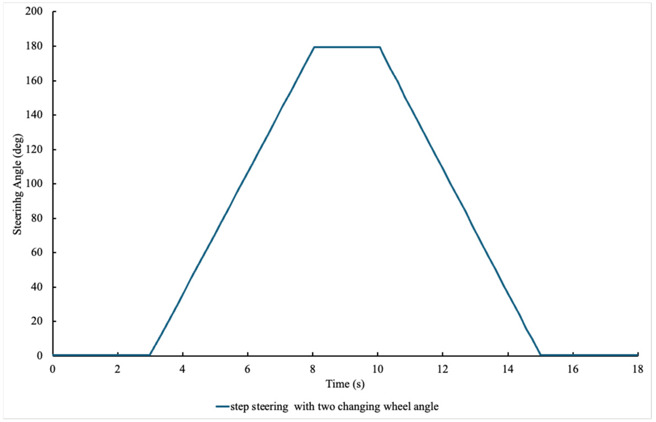
Figure 10c.
Figure 9 illustrates the two-step steering command, involving a quick increase and return of the steering angle to simulate consecutive steering actions during an evasive maneuver.
Figure 10.
(a) steady state maneuver path, (b) step steering maneuver path with one changing wheel angle, (c) step steering maneuver path with two changing wheel angle. Point a demonstrates the start point of path while point b shows the end point of the path.
Figure 10.
(a) steady state maneuver path, (b) step steering maneuver path with one changing wheel angle, (c) step steering maneuver path with two changing wheel angle. Point a demonstrates the start point of path while point b shows the end point of the path.
The performance of vehicles with more than two axles or wide dual tires, typical features of heavy-duty vehicles, is significantly influenced by the acceleration of the center of gravity and the curvature of the path during steady-state conditions. To properly understand the steady-state behavior of such vehicles, it is essential to conduct cornering tests across a range of radii, thereby inducing different center-of-gravity accelerations. These evaluations can be carried out using either constant-radius tests at increasing speeds or constant-speed tests with varying steering angles. Ideally, both types of tests should be conducted to achieve a comprehensive understanding of steady-state cornering performance [
37].
In a constant-radius test, the vehicle is driven at a fixed radius while its speed is gradually increased. This procedure allows for the analysis of control steer response characteristics and dynamic stability. To fully characterize the cornering behavior, the test must be repeated for various radii. The flexibility of this method depends on the test vehicle’s capabilities and the availability of loops or test tracks with appropriate curvature [
38,
39].
In this study, the truck’s speed was gradually increased from low to high for each test case. Throughout the test, tire contact with the ground was continuously monitored, and no lift-off was observed until the critical speed was reached. The results of two representative tests are presented below, and the final critical speeds for each turning radius are summarized at the end of this section.
5.3. Results of the Steady-State Steering Test
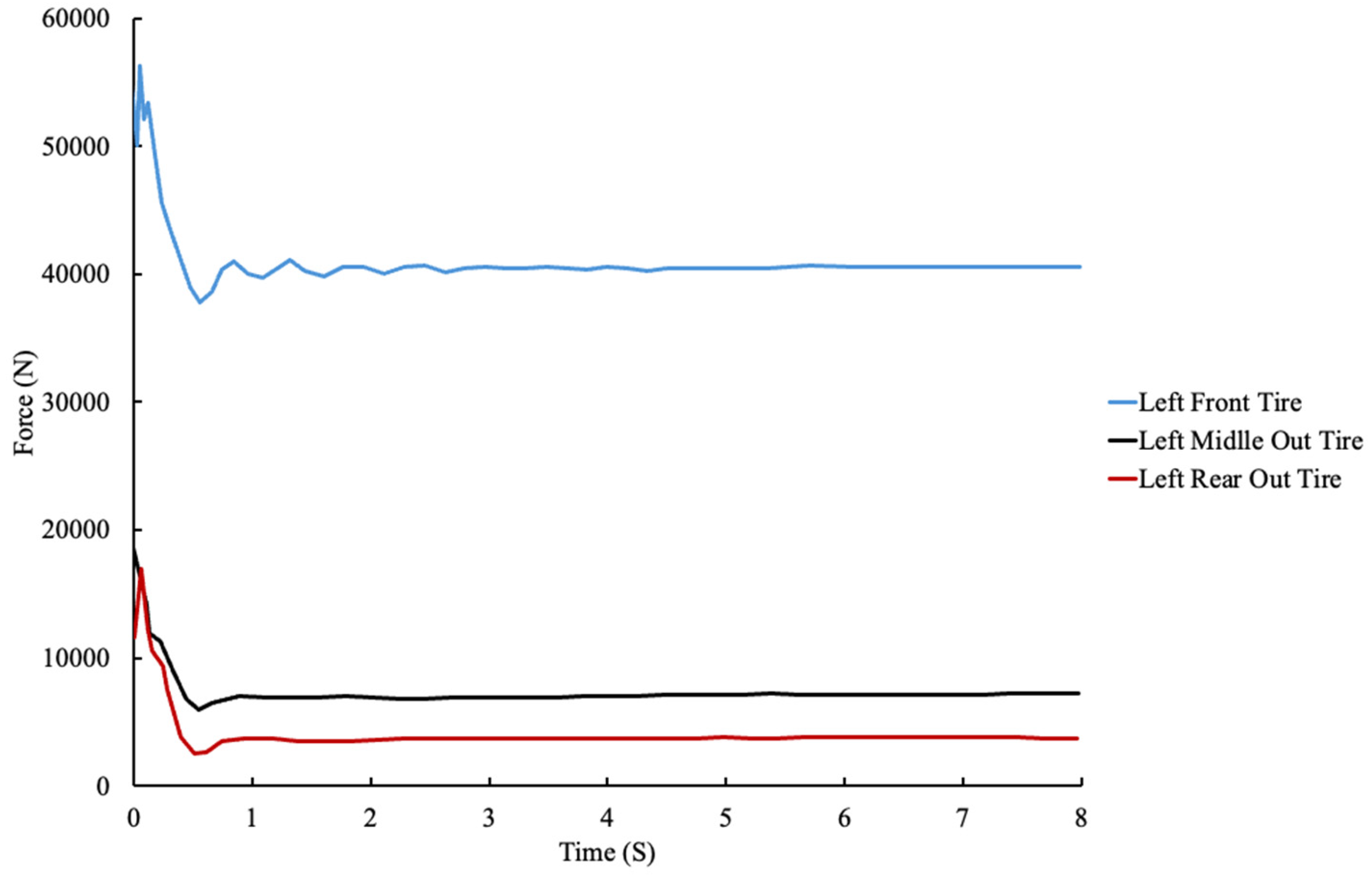
A steady-state steering test with a turning radius of 80 m was performed to evaluate the rollover behavior of the loaded truck mixer. The vehicle was driven at speeds ranging from 30 to 55 km/h, and as shown in
Figure 11, the left-side rear tires begin to lift off the ground at the upper speed range during a left-hand turn, indicating the onset of rollover. This test is presented as a representative example of the steady-state simulations conducted at various turning radii. While the same procedure was applied across all tested radii, the 80 m case is shown here to illustrate the typical dynamic response of the vehicle and the method used to determine the critical speed threshold for rollover.
Similarly,
Figure 12 presents the left-side vertical tire forces at a speed of 65 km/h, illustrating the last stable condition before tire lift-off occurs. This speed was identified as the maximum safe speed at which all tires maintain contact with the road surface, ensuring vehicle stability and safety under the tested conditions.
5.4. Results of Steady-State Tests for Turning Radii from 10 to 100 m
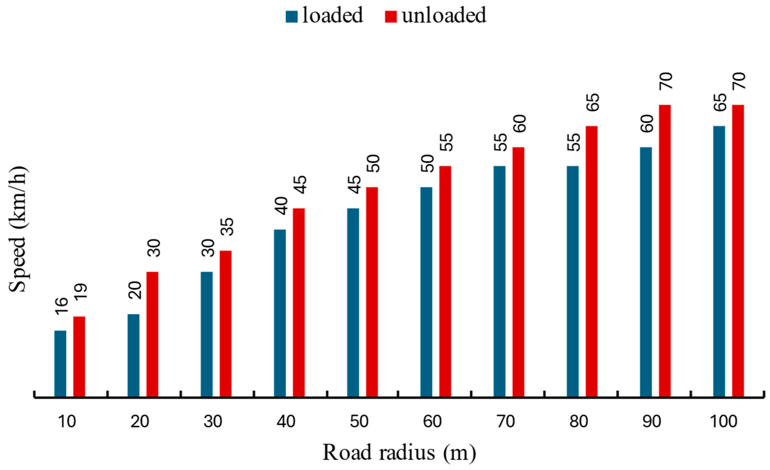
Figure 13 illustrates the maximum safe speeds achieved at various turning radii. As expected, larger turning radii correspond to higher maximum speeds before rollover occurs. Moreover, unloaded trucks consistently exhibit higher maximum speeds compared to their loaded counterparts, with the difference becoming more pronounced at larger radii. Speeds are expressed in kilometers per hour (km/h), and turning radii are measured in meters (m).
It can be observed important differences in the behaviour of the vehicle for very low road radius and low speeds. We can explain that this is a risky point during very low speed manoeuvres that we propose to control more carefully. From that, the gap is apparently constant and equal to 5 km/h.
The results demonstrate that unloaded truck mixers consistently achieve higher rollover speeds compared to their loaded counterparts across all tested turning radii. This difference primarily stems from the lower center of gravity in the unloaded condition, which significantly enhances vehicle stability by reducing the overturning moment generated during lateral maneuvers. Furthermore, the absence of fluid inside the tank eliminates the dynamic effects of fluid sloshing, thereby minimizing additional destabilizing forces that typically arise from the motion of the concrete mixture. Conversely, loaded trucks experience increased inertia due to the mass of the concrete and the complex movement of the partially filled rotating tank, both of which amplify lateral forces and moments during sharp turns or high-speed cornering. These dynamic fluid forces introduce additional variability and challenge the vehicle’s ability to maintain tire contact with the road surface, lowering the rollover threshold. Collectively, these findings highlight the critical influence of load distribution and center of gravity height on rollover risk and underscore the importance of incorporating load-aware mechanisms in safety systems to effectively prevent rollover accidents in concrete truck mixers. An important deviation in vehicle behavior is observed at small turning radii and low speeds. Despite the lower kinetic energy involved, these conditions present elevated rollover risk due to the sharp steering angles and the associated dynamic load transfer. This indicates a critical need for more precise control strategies during low-speed, tight-turning maneuvers, which are common in urban delivery operations.
5.5. Results of Step Steering State Tests with One-Step and Two-Step Steering Angles
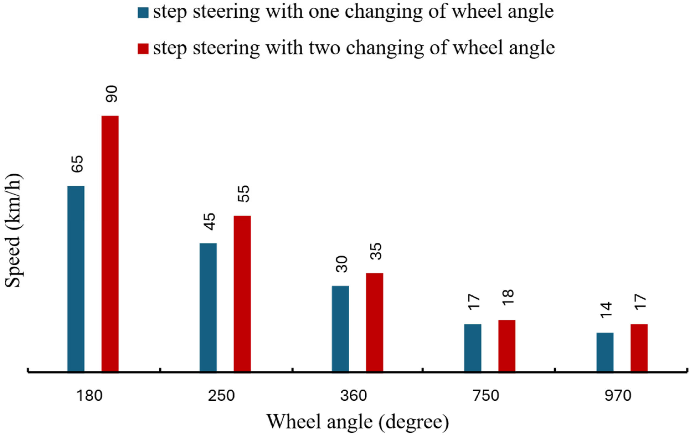
Figure 14 illustrates the maximum speeds corresponding to different wheel angles (180, 250, 360, 750 and 970 degree), with speeds measured in kilometers per hour and wheel angles in degrees. As anticipated, increasing the wheel angle results in reduced maximum speeds for the truck. Additionally, this figure presents a comparison between one-step and two-step changes in the wheel angle for each angle.
The step steering test results reveal critical insights into the dynamic behavior of the truck mixer under varying steering conditions. This test, conducted for both one-step and two-step steering angles ranging from 180° to 970°, highlights the impact of steering magnitude and maneuver complexity on vehicle stability.
For one-step steering, the results indicate a progressive reduction in the maximum allowable speed as the steering angle increases. For example, at a steering angle of 180°, the truck maintains stability at relatively higher speeds, while at 970°, the maximum speed drops significantly. This behavior is attributed to the increased lateral forces and moments induced by sharper steering angles, which challenge the vehicle’s ability to maintain tire-road contact.
In the two-step steering test, where the steering angle changes twice within the maneuver, the results show a slightly higher rollover threshold compared to the one-step test. This can be explained by the smoother transition of lateral forces, allowing the vehicle’s suspension and tires to adapt more effectively to the dynamic loading conditions. However, the overall trends remain consistent, with higher steering angles resulting in lower maximum speeds.
These findings underscore the sensitivity of rollover thresholds to steering input and highlight the importance of precise vehicle control during sharp maneuvers. They also provide a basis for calibrating the proposed warning system, as it can account for both single and multi-step steering dynamics when issuing alerts to drivers.
6. Proposed Rollover Warning System Based on Critical Speed Monitoring
In light of the extensive test results and analysis presented in this study, the development of a proposed rollover warning system is considered as a practical step toward accident prevention. Given the severity of truck rollover incidents, often resulting in significant damage and casualties, such a system can play a critical role in enhancing operational safety. As illustrated in
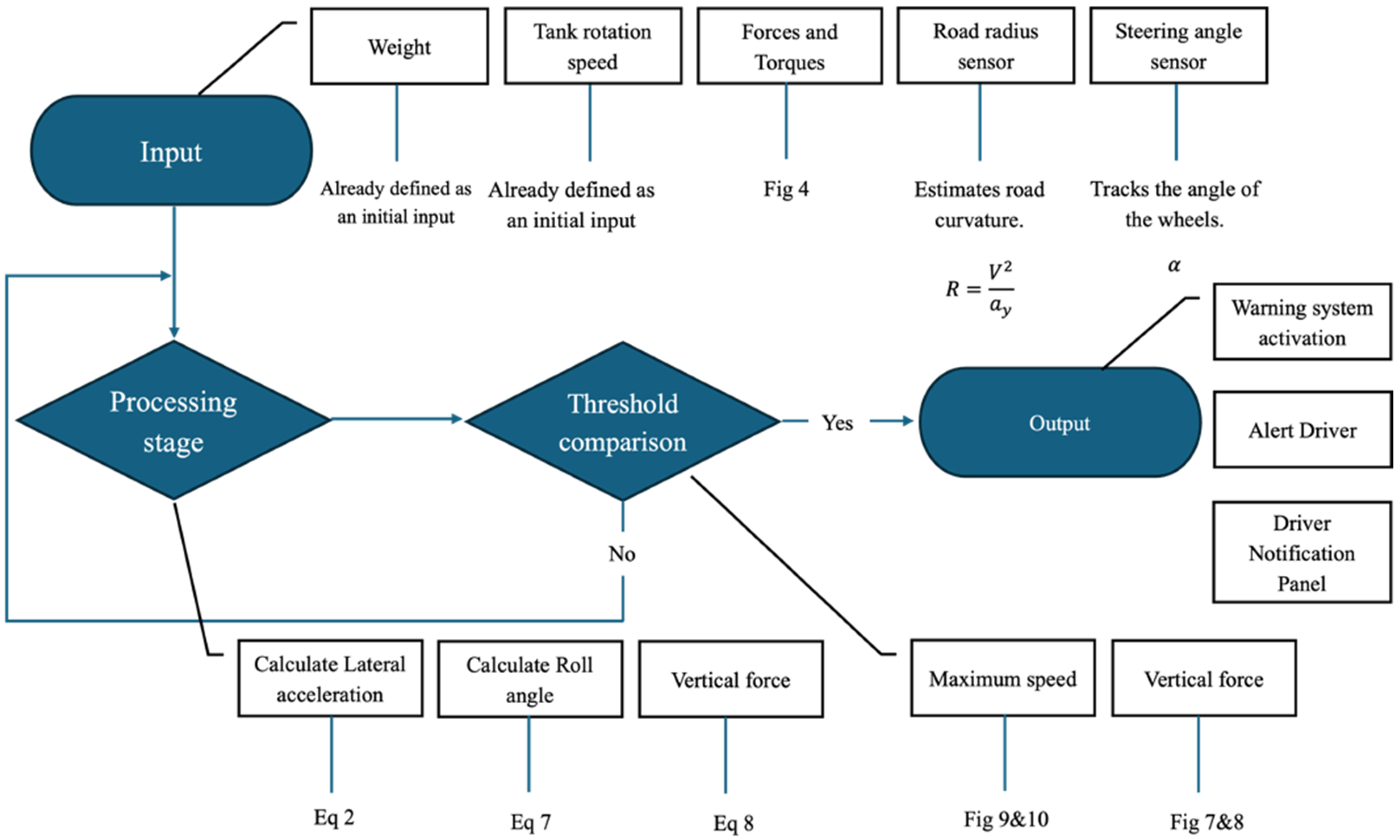
Figure 15 and
Figure 16, the proposed system is designed to continuously monitor both road conditions and the vehicle’s current dynamic state. A key aspect of the concept involves the use of a virtual axis, which is introduced to simplify the tracking of lateral motion. When the distance between the virtual axis and the truck’s longitudinal centerline is less than 1.5 m, and the chassis stiffness is high (a necessary condition in a concrete truck mixer), the virtual axis can be validly considered as representative of the vehicle’s behavior. This threshold ensures that the kinematic approximation remains sufficiently accurate for real-time monitoring, enabling the system to operate effectively without requiring complex real-time modeling.
This includes parameters such as the weight, the steering angle, the rotation speed of the tank, and the radius of the road, which can be utilized as initial variables. These values, combined with the two equations of lateral acceleration of Equation (2) and rolling angle which can be seen below as Equation (7) (where
is roll stiffness of front virtual axis and
is rear virtual axis’s roll stiffness) and the data from
Figure 7, can be used to demonstrate an unexpected situation to the driver through a warning system.
With a simple simplification and by assuming
, it is clear:
To validate the previously identified rollover speed for the truck, additional equations (Equations (8)–(10) are introduced to cross-check this value. By applying these equations, focused on the accurate calculation of vertical forces, the point at which these forces approach zero, indicating a loss of contact with the road surface, can be determined and compared with
Figure 11 and
Figure 12. This combined approach strengthens the accuracy of the rollover speed assessment.
Here, represents the vertical force on the rear virtual axis, denotes the vertical force of the sprung mass, and indicates the vertical force of the unsprung mass.
System Purpose and Operation
The warning system aims to enhance safety by providing truck mixer drivers with alerts when rollover risks increase. By continuously evaluating the likelihood of rollover through monitoring critical dynamic parameters such as lateral acceleration, roll angle, tank rotation speed, road radius, and steering angle the system leverages insights from extensive stability testing to track vehicle stability dynamics [
40,
41,
42,
43]. It issues warnings to drivers before critical operating limits are approached, thus helping to prevent potential rollover conditions. The system operates in real-time, delivering prompt alerts to guide safe vehicle handling, especially when monitored parameters indicate an elevated rollover risk. It identifies lateral acceleration, roll angle, and road curvature as key indicators due to their strong correlation with rollover risk. Using CFD and TruckSim software simulations, the system assesses vehicle stability under various driving scenarios. By employing onboard sensors and data-processing algorithms, it utilizes core equations for lateral acceleration and roll angle to dynamically adjust thresholds.
Figure 16 illustrates the streamlined functionality of the warning system. Input parameters such as the weight of the truck and loaded tank, along with the tank’s rotational speed, are defined as initial values for tank’s simulation and analysis which are used in the first stage to calculate the forces and torques that are shown in
Figure 6 and will later be used as inputs for maneuver tests. Additional inputs, including steering angle and road radius, are employed to classify the maneuver test into the appropriate category for subsequent processing. Based on these inputs, the system selects the correct test results and computes the lateral acceleration using Equation (2), roll angle from Equation (7) and vertical forces derived from Equation (8). The threshold comparison process is then initiated. During this stage, as a result of the computed data, including inputs and measured values and maximum speed defined by maneuver condition (derived from test results shown in
Figure 13 and
Figure 14, as well as vertical force data from
Figure 11 and
Figure 12) are compared against the current speed of the truck. If the truck’s speed approaches the maximum allowable limit, the warning system activates, sending an alarm to the driver.
As an example, consider a truck mixer navigating a 50 m radius turn, where the system continuously monitors the truck’s speed and lateral acceleration, with a 68% load and a tank rotation speed of 3 rpm. As the truck’s speed is checked in real time, the system compares it to a predefined safety threshold of 50 km/h. When the truck’s speed approaches this limit, an immediate warning signal is activated to alert the driver.
Similarly, when the truck is on a straight path and initiates a sharp 180° steering maneuver, the system monitors speed and continuously assesses stability. If the speed approaches a set threshold of 65 km/h, the warning system immediately triggers an alert to the driver. Additionally, if the truck must perform the 180° steering maneuver in two steps, the system activates the warning signal when the speed nears 90 km/h. This ongoing comparison against specific safety limits ensures timely alerts based on real-time data, enhancing operational safety.
Another significant advantage of this warning system is its practicality and cost-effectiveness. Since all necessary sensors and measurements for input and processing are already installed on the truck, the system requires no additional components. This makes it an affordable solution capable of preventing substantial damage and reducing associated costs. The alert system could be combined visual and audio cues designed to capture attention without causing distraction. Dashboard indicators highlight the specific risk factor nearing its limit, whether it be lateral acceleration, roll angle, or road curvature. Audible warnings provide an immediate signal, while an adaptive feedback loop temporarily pauses alerts if the driver adjusts speed or steering angle, thereby minimizing alert overload and ensuring support without intrusiveness.
It should be mentioned that the proposed warning approach is scalable to different truck-mixer models because it depends on geometric and mass parameters rather than a specific vehicle layout. By updating inputs such as total mass, drum volume, fill ratio, and track width, the same workflow can generate new rollover thresholds using CFD and TruckSim® (2020.0). The resulting limits are then embedded in the same warning algorithm, allowing straightforward adaptation to various mixer sizes and chassis configurations without modifying the underlying system logic.
8. Discussion
This study contributes to the formalization of rollover risk in heavy-duty vehicles by establishing a structured pipeline that connects high-fidelity physical simulation with real-time, sensor-based decision logic. Unlike conventional safety assessments that treat simulation results as ends in themselves, the proposed framework explicitly translates simulation-derived forces and vehicle responses, such as tire lift-off, tank slosh dynamics, and lateral acceleration, into threshold-based knowledge structures.
This transformation enables the abstraction of complex, transient vehicle behaviors into actionable rules encoded in onboard logic. Through this lens, the CFD and multibody dynamics models serve not only to simulate but to inform and validate a generalized knowledge representation. This representation, grounded in physical phenomena, can be operationalized using common sensor inputs such as roll angle, curvature, and speed, effectively bridging the gap between rich simulation environments and embedded vehicular control systems. Moreover, the proposed method demonstrates how engineering knowledge can be formalized across layers of fidelity. The system identifies critical vehicle states through simulation and expresses them through real-time estimators and warning rules.
While the case study focuses on concrete mixers, the framework is extensible to other applications involving mobile systems with dynamic payloads, such as fire engines, fuel tankers, or even autonomous utility vehicles.
To summarize the core contributions and findings:
Advanced CFD Modeling of Tank Behavior:
- ○
Simulated non-Newtonian concrete behavior (viscosity = 20 N·s/m2, density = 2400 kg/m3) inside a rotating tank using the Volume of Fluid (VOF) method in ANSYS Fluent (2023 R2).
- ○
Applied lateral accelerations ranging from 0 g to 0.6 g to simulate real driving conditions.
- ○
Extracted lateral forces, vertical forces, and torques, showing linear trends suitable for vehicle-level application.
Realistic Vehicle Dynamics Assessment via TruckSim® (2020.0):
- ○
Built a detailed vehicle model with accurate suspension and mass parameters.
- ○
Conducted simulations under both loaded (68%) and unloaded (steady-state steering test) configurations for:
- ▪
Steady-state cornering tests at turning radii of 10, 20, 30, 40, 50, and 100 m.
- ▪
Step steering tests with steering angles of 180°, 250°, 360°, 750°, and 970°, using both single and two-step input formats.
- ○
Identified critical speeds for rollover onset based on tire lift-off.
Key Factors Influencing Rollover:
- ○
Increased load height and fluid motion amplify rollover tendencies.
- ○
Dynamic effects from tank rotation and lateral fluid shifting play a crucial role.
- ○
Road curvature, steering input, and load condition were all major contributors to rollover susceptibility.
Design of a Cost-Effective Rollover Warning System:
- ○
Uses only standard onboard sensors: steering angle, vehicle speed, tank load status, and drum rotation speed.
- ○
Calculates real-time lateral acceleration and roll angle using verified equations from this study.
- ○
Compares current state to maneuver-specific safety limits extracted from simulations.
- ○
Issues audio-visual warnings when risk thresholds are approached.
- ○
Example scenarios:
- ▪
50 m radius turn, 68% load → warning at ~50 km/h.
- ▪
180° steering, single-step → warning at ~65 km/h.
- ▪
180° steering, two-step → warning at ~90 km/h.
- ○
No extra hardware required, ensuring economic scalability for fleet-wide deployment.
Analytical Validation:
- ○
The simulation results were cross-validated with derived equations for lateral acceleration, roll angle, and vertical load transfer, confirming the accuracy of both the CFD and TruckSim® (2020.0) models.
- ○
Theoretical rollover speeds calculated via static and dynamic equations aligned well with simulation outcomes, reinforcing the system’s reliability.
Broader Impacts:
- ○
Enhances safety and operational reliability for concrete truck fleets and other heavy-duty vehicles.
- ○
Contributes to traffic accident prevention, project continuity, and environmental protection by mitigating rollover-related concrete spills.
Paves the way for future research on:
- ○
Integration with GPS, V2X, or road mapping systems for terrain-aware safety control.
- ○
Development of adaptive or predictive stability systems using AI or machine learning.
- ○
Experimental validation with full-scale vehicle testing or hardware-in-the-loop setups.
- ○
Inclusion of additional complex maneuvers, such as double lane change or emergency swerve tests, to broaden the rollover risk database and further refine the decision logic of the warning system under dynamic and high-risk scenarios.
9. Conclusions
This study presents a novel approach to analyzing rollover risks in concrete truck mixers using CFD simulations and vehicle dynamics modeling. The application of forces and moments derived from fluid–structure interactions into TruckSim® (2020.0) software offers a more accurate representation of the vehicle’s behavior under real-world conditions, addressing prior limitations that overlooked the complex dynamics of rotating drums and viscous cargo. This comprehensive methodology not only enhances our understanding of rollover thresholds but also establishes a foundation for practical, intelligent safety systems tailored to the unique operational risks of concrete truck mixers.
Extensive simulations, including steady-state steering and step steering maneuvers, were performed under a range of operational conditions and load states to identify critical rollover thresholds. For example, at a turning radius of 80 m, the truck mixer exhibited a critical rollover speed of 55 km/h when loaded (68% fill) and 65 km/h when unloaded, highlighting the pronounced influence of mass distribution and fluid motion on stability (with up to 15–18% variation in risk). These simulations also informed the design of a real-time rollover warning system that uses only standard onboard sensors, requiring no additional hardware.
Beyond the engineering implementation, this framework exemplifies how simulation-derived physical behaviors can be abstracted into a structured, rule-based knowledge model, suitable for real-time interpretation and computational reasoning.
This contributes to the broader aim of formalizing engineering knowledge, aligning with ongoing efforts in engineering informatics to create reusable, domain-transferable decision logic from complex physical simulations.
In conclusion, this integrative simulation and safety framework provides a robust, validated, and scalable solution for preventing rollover incidents in concrete truck mixers. By combining high-fidelity simulations with analytical models to inform real-time risk prediction, the proposed system represents a significant advancement in heavy-vehicle safety and offers a practical roadmap for both immediate and future implementation in transport operations. The strategy developed in this study adapts the warning and driver-assistance thresholds to the operating conditions of the mixing tank and the vehicle’s dynamic behavior, allowing these thresholds to be used directly or to narrow the operating ranges of other driver-assistance systems for improved accuracy. Moreover, by benchmarking the proposed system against commercial ESC and RSC technologies, this study demonstrates its strong potential as a practical, low-cost alternative specifically optimized for the rollover characteristics of mixer trucks.


