Article

Multi-Objective Optimization of Torque Motor Structural Parameters in Direct-Drive Valves Based on Genetic Algorithm

1
School of Mechanical and Electrical Engineering, Northeast Forestry University, Harbin 150040, China
2
Beijing Institute of Spacecraft Environment Engineering, Beijing 100094, China
3
School of Mechanical Engineering, Harbin Institute of Technology, Harbin 150006, China
*
Author to whom correspondence should be addressed.
Actuators 2025, 14(11), 527; https://doi.org/10.3390/act14110527
Submission received: 27 September 2025 / Revised: 26 October 2025 / Accepted: 27 October 2025 / Published: 29 October 2025
(This article belongs to the Special Issue Design, Hydrodynamics, and Control of Valve Systems)

Abstract

This paper presents a genetic algorithm (GA) approach to optimize key structural parameters of the torque motor used in a direct-drive slide knife gate valve. The optimization aims at enhancing the performance of the torque motor by improving the output torque, minimizing the overshoot, and reducing the response time. A mathematical model based on these performance indicators is formulated to guide the optimization process. Compared to the original design, the optimized design is shown to achieve a 26.4% increase in output torque, a 0.14 ms reduction in response time, and a 9% decrease in overshoot. Additionally, AMESim simulations confirm that the optimized motor significantly improves valve control accuracy, dynamic response, and flow stability, while also decreasing sensitivity to pressure fluctuations under high-current conditions. Finally, experimental results are provided to corroborate the simulation findings, validating the accuracy and effectiveness of the proposed optimization methodology. This study provides novel theoretical insights and practical guidance for the design of high-performance torque motors used in direct-drive electro-hydraulic servo valves within aerospace applications.

1. Introduction

In recent years, direct-drive valves (DDVs) have played a vital role in aero-engine fuel metering systems due to their high reliability and excellent dynamic performance [1]. As an innovative DDV design, the direct-drive slide knife gate valve utilizes a torque motor to directly drive the slide knife in rotational motion. This fundamentally eliminates the complex hydraulic pre-stage, thereby overcoming the manufacturing challenges inherent in traditional electro-hydraulic servo valves. This design offers a promising solution for high-dynamic and high-precision fuel control. However, this direct-drive method, which lacks mechanical stops, while enhancing the system’s response speed, also renders the static and dynamic characteristics of the whole valve highly sensitive to the output performance of the torque motor [2]. Nonlinearities in the torque motor can be directly transmitted and amplified, leading to prevalent technical challenges in practical engineering applications, such as excessive overshoot and prolonged response time [3]. As the core actuator of this valve, the output characteristics of the torque motor are decisive for the whole valve performance [4,5]. Consequently, breaking through the performance barriers of the direct-drive slide knife gate valve necessitates a thorough investigation and enhancement of the dynamic performance of its torque motors [6,7].
To improve the performance of the torque motor, research on traditional designs has primarily focused on enhancing the output torque through structural modifications. Zhang et al. [8] introduced a radial–axial hybrid magnetization method. Yan et al. [9] quantified the magnetic saturation region and refined the magnetic circuit model. Additionally, Rao et al. [10] systematically investigated the influence of assembly deviation, the limiting aperture of the upper iron block, and air gap symmetry on the output torque. Although these studies have made progress in enhancing torque, current research on torque motors still has significant limitations: the optimization objective remains singular, focusing primarily on enhancing torque output; additionally, there is a lack of systematic simulation validation for the transient response process [11,12].
To address these limitations, multi-objective optimization has been widely adopted to improve the design of high-torque permanent magnet synchronous motors (PMSMs) [13,14,15]. Oh, J.-A. and Xie, F. [16,17] developed a multi-objective optimization framework for PMSMs. In the context of brushless DC motor design, Salarian et al. [18] evaluated three optimization algorithms: particle swarm optimization, simulated annealing, and the red deer algorithm. Another approach was proposed by Chai et al. [19], who integrated a hierarchical design parameter structure with a support vector machine (SVM) method for multi-objective optimization. By adopting multi-objective optimization, scholars have not only effectively reduced cogging torque but also improved the overall performance of the torque motor [20].
As a primary optimization method, the GA has been successfully applied to a range of electromechanical design problems, including the optimization of permanent magnet couplings [21], the structural optimization of PMSMs [22,23,24], and the structural optimization of a composite cylinder [25]. Although multi-objective GA optimization has been demonstrated to be highly effective in multiple fields, its potential has not been systematically explored for resolving the fundamental compromise in torque motors for direct-drive slide knife gate valves—specifically, the inherent trade-off between high output torque and superior dynamic response. In particular, the systematic coordination of these competing objectives through the GA to directly enhance the dynamic performance of the whole valve remains an underexplored area.
Based on the above research, this paper aims to optimize the torque motor of a direct-drive slide knife gate valve to achieve higher output torque, lower overshoot, and a faster response time. The GA is employed to perform a multi-objective optimization of the torque arm, air gap, and coil turns. Compared to the original model, the optimized model demonstrates higher optimization efficiency and significantly improved performance.
This paper is organized as follows. Section 1 provides the introduction. Section 2 establishes the mathematical model of the torque motor. Section 3 investigates the influence of key structural parameters on the performance of the torque motor. Based on this analysis, Section 4 describes the implementation of the GA for parameter optimization. Section 5 then evaluates the impact of the optimized motor design on the performance of the whole valve. Section 6 presents experimental results that validate the optimization approach and the accuracy of the theoretical model. Finally, Section 7 summarizes the main conclusions of this paper.

2. Mathematical Model of the Torque Motor

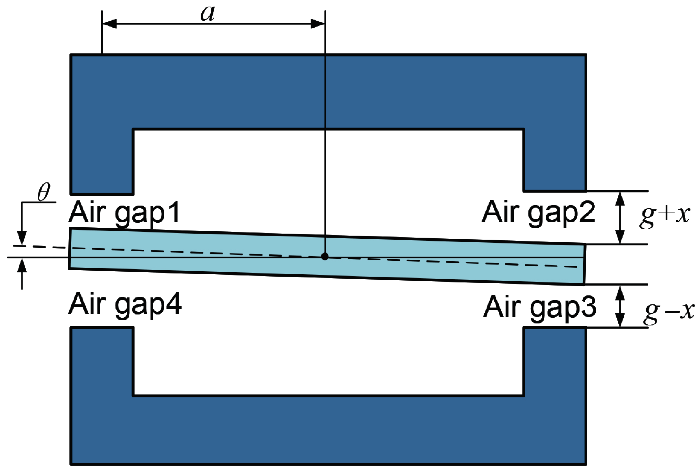
This paper intends to optimize the torque motor of a direct-drive slide knife gate valve. The operating principle is illustrated in Figure 1. Under the combined action of the fixed flux from the permanent magnet and the control flux generated by the coil, the flux increases in air gaps 1 and 3, while the flux decreases in air gaps 2 and 4. This imbalance generates a clockwise torque on the armature assembly, driving the slide knife gate to deflect and achieve precise hydraulic flow control.
Based on the operating principle, an equivalent magnetic circuit model of the torque motor is constructed, as shown in Figure 2. The model accounts for magnetic flux leakage in the magnets, coils, and air gaps. The labels 1, 2, and 3, respectively, represent the permanent magnet, the air gap, and the leakage flux at the control coil. Based on the magnetic flux leakage introduction, the magnetic flux utilization coefficients are denoted as α , β , and γ .
Based on Maxwell’s electromagnetic theory [26], the electromagnetic force acting on the armature in a magnetic field can be expressed as follows:
F = ϕ 2 2 μ 0 A g
where ϕ represents the interpolar magnetic flux, A g represents the pole area at the air gap, and μ 0 represents the magnetic permeability of air.
When the servo valve is not operating, the armature is not deflected, and the magnetic resistance of each air gap can be expressed as follows:
R g = g μ 0 A g
where g represents the air gap length.
When current is applied and the armature deflects, the reluctances of air gaps 1 to 4 are as follows:
R g 1 = R g 3 = g x μ 0 A g = R g 1 x g
R g 2 = R g 4 = g + x μ 0 A g = R g 1 + x g
where x denotes the displacement of the armature end from the neutral position.
Based on the law of magnetic flux continuity and Kirchhoff’s second law for magnetic circuits, a detailed analysis of the five nodes and four closed loops in the magnetic circuit model shown in Figure 2 is performed. The following results are obtained:
α ϕ 8 = ϕ 1 + ϕ 5 ϕ 2 = ϕ 5 + α ϕ 9 ϕ 1 = ϕ 4 + β ϕ 6 ϕ 3 = ϕ 2 + β ϕ 6 ϕ 3 = ϕ 7 + α ϕ 9 M 0 / 2 = R m / 2 ϕ 8 + R n ϕ 1 + γ R g 1 ϕ 1 + γ R g 2 ϕ 4 + R n ϕ 4 M 0 / 2 = R m / 2 ϕ 9 + R n ϕ 2 + γ R g 2 ϕ 2 + γ R g 1 ϕ 3 + R n ϕ 3 N i = R d ϕ 6 + R n ϕ 1 + γ R g 1 ϕ 1 R n ϕ 2 γ R g 2 ϕ 2 R f ϕ 5 N i = R d ϕ 6 + R n ϕ 3 + γ R g 1 ϕ 3 R n ϕ 4 γ R g 2 ϕ 4 + R f ϕ 7
where α denotes the leakage coefficient of the permanent magnet, β denotes the leakage coefficient of the coil, and γ denotes the leakage coefficient of the air gap.
When the armature is in the neutral position, the control flux ϕ c and the fixed magnetic flux ϕ g can be expressed as follows:
ϕ c = β γ N i R c = β γ N i 2 β γ R g + 2 β R n + 2 R d + β R f
ϕ g = α γ M 0 R a = α γ M 0 2 α γ R g + 2 α R n + R m
The magnetic circuit can be analyzed using the following relations, where R c represents the total reluctance of the control flux loop and R a represents the total reluctance of the fixed flux loop.
By combining Equations (3)–(7), the magnetic fluxes ϕ 1 to ϕ 9 can be obtained, where the magnetic fluxes ϕ 1 and ϕ 2 pass through air gaps 1 and 2.
ϕ 1 = 1 + 4 α γ R g x g R a ϕ c + 1 + 2 β γ R g x g R c ϕ g d γ d x g 2
ϕ 2 = 4 α γ R g x g R a 1 ϕ c + 1 2 β γ R g x g R c ϕ g d γ d x g 2
d = R a R c 8 α β γ 2 R g 2
During the movement of the armature, since the magnetic flux density in the diagonal air gap remains the same, the output torque expression can be simplified as follows:
T d = 2 a ( F 1 F 2 ) = a μ 0 A g ( ϕ 1 2 ϕ 2 2 )
Substituting Equations (8) and (9) into Equation (11) yields the expression for the output torque.
T d = a μ 0 A g 2 ϕ c + 4 β γ R g x g R c ϕ g 4 α γ R g x g R a ϕ c + 2 ϕ g d γ d ( x / g ) 2 2
As current flows through the coil, the armature poles are magnetized due to electromagnetic effects. At the right end, magnetic repulsion is produced between the armature and the upper magnetic conductor, while magnetic attraction occurs between the armature and the lower magnetic conductor. This pair of opposite magnetic forces acts on the armature at non-collinear points, creating a force couple that generates torque around the rotational axis, as shown in Figure 3.
The geometric relationship shown in Figure 3 indicates a correlation between the offset and the armature deflection angle.
x = a θ ,
where θ represents the armature deflection angle.
Combining Equations (6), (7), (12) and (13) yields the final output torque formula:
T d = K i 1 + η ξ 2 x g 2 Δ i + K m 1 + η ϕ c ϕ g 2 θ d d x g 2 2
K t = 2 N ϕ g a g ξ γ 2
K m = 4 ϕ g 2 R g a g 2 ξ γ 2
ξ = 2 β γ R g R c
η = α R c β R a
where K t represents the torque constant of the torque motor, K m represents the magnetic spring stiffness of the torque motor, and ξ and η represent the magnetic resistance coefficients.
Equation (14) expresses the relationships between the output torque of the torque motor, the current, and the armature deflection angle. Based on the relationship between the control flux and the fixed flux, as well as the air gap, and ensuring that x / g 1 and ( ϕ c / ϕ g ) 2 1 , the output torque formula can be simplified.
T d = K t Δ i + K m θ
The static characteristics of a torque motor refer to the relationship among the output torque, the current, and the armature deflection angle. The input current in the control coil creates an uneven distribution of electromagnetic force across the air gap of the torque motor, causing the armature assembly to deflect and generate output torque.
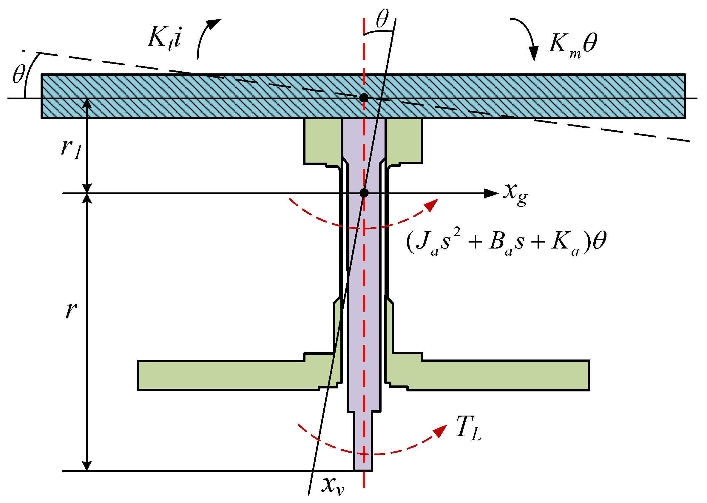
The dynamic equilibrium equation for the armature assembly is the balance between the output torque and the combined effects of the rotational inertia torque, damping torque, spring tube feedback torque, and load torque [27]. The armature assembly undergoes force analysis, as shown in Figure 4.
T d = K t Δ i + K m θ = J a d 2 θ d t 2 + B a d θ d t + K a θ + T L
where J a represents the rotational inertia of the armature assembly, B a represents the rotational damping of the armature assembly, K a represents the composite stiffness of the armature assembly, and T L represents the external load.
The Laplace transform is applied to the equation above:
K t Δ i + K m θ = ( J a s 2 + B a s + K a ) θ + T L
The transfer function for the armature deflection angle is as follows:
θ = K t Δ i T L J a s 2 + B a s + K a K m

3. Simulation Analysis of the Torque Motor

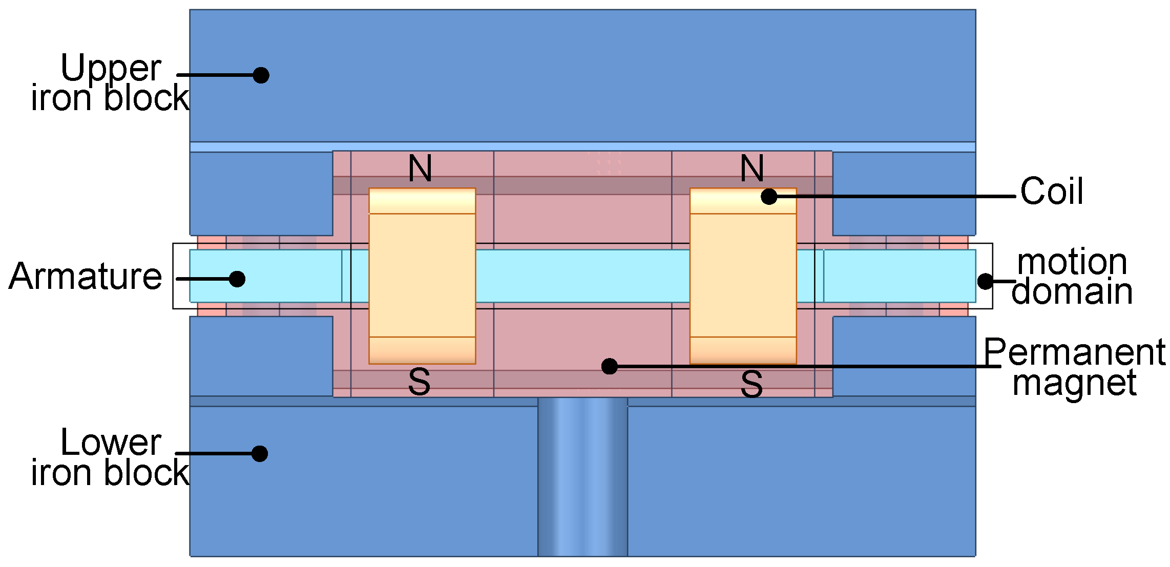
To systematically investigate the intrinsic influence mechanism of key structural parameters on the static characteristics and dynamic response of torque motors, a finite element analysis (FEA) approach based on electromagnetic theory is employed. A refined three-dimensional finite element model of the torque motor is constructed, as shown in Figure 5. Numerical simulations and quantitative analyses are conducted under various structural parameter configurations. The simulation results are shown in Figure 6, Figure 7 and Figure 8. A theoretical foundation and a data basis are provided for the structural optimization design of torque motors.
The output torque is found to have an inverse relationship with the air gap. According to the simulation results, when the air gap increases from 0.7 mm to 0.9 mm, the output torque decreases by 0.086 N·m, representing a reduction of 29.06%. The overshoot is observed to decrease overall by 9.8%, but the response time increases from 2.04 ms to 2.47 ms, representing an increase of approximately 21.08%. These results suggest a clear monotonic relationship between the static and dynamic characteristics of the torque motor and the air gap. However, the optimization for high output torque and fast response time inherently leads to an increase in overshoot, revealing a fundamental trade-off among these characteristics.
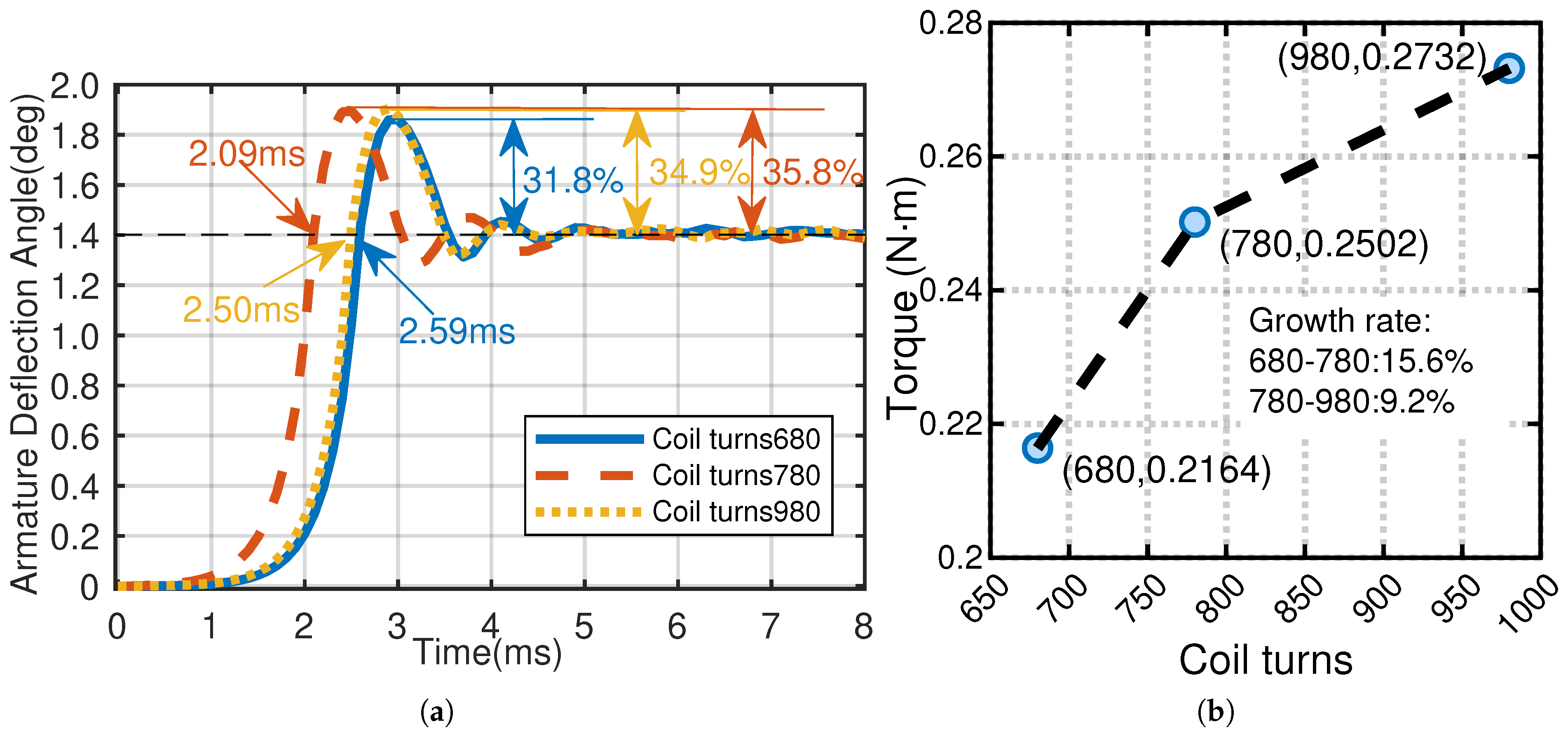
The output torque is positively correlated with the number of coil turns. It is observed that increasing the coil turns from 680 to 980 leads to a rise in torque by 0.057 N·m, corresponding to an increase of 26.25%. However, the effect of the number of coil turns on the dynamic response is non-monotonic. When the turns are increased from 680 to 780, the inductance and electromagnetic stiffness increase, while damping decreases, resulting in a larger overshoot. If the coil turns are further increased to 980, although the inductance continues to rise, copper losses become significantly greater, and the associated damping effect reduces the overshoot. Additionally, whether the number of turns is increased or decreased from that in the original model, the response time is increased. Thus, the output torque can be increased by increasing the number of coil turns, which degrades the system’s responsiveness by increasing the time constant.
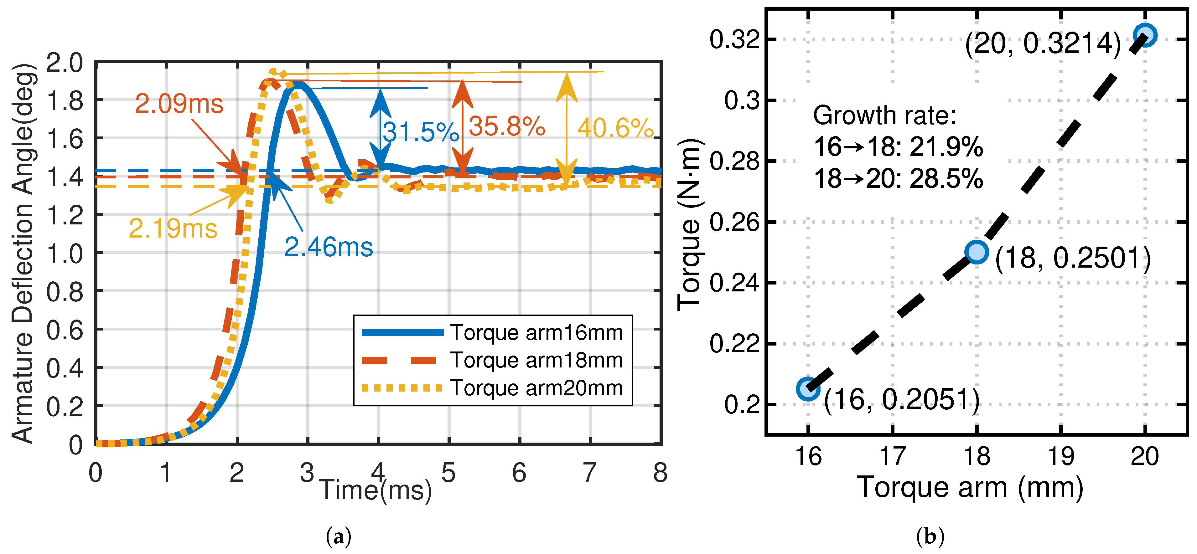
The output torque increases significantly as the torque arm length is extended. When the torque arm length is increased from 16 mm to 20 mm, the output torque rises by 0.12 N·m, representing a 56.7% increase. Concurrently, the overshoot gradually increases, ultimately reaching 40.6%. Notably, at a torque arm length of 20 mm, the response time is 2.19 ms, which is not the maximum observed. In contrast, when the length is reduced to 16 mm, although the overshoot is minimized, the response time increases to 2.46 ms, the longest among all configurations. The results indicate that a reasonable increase in torque arm length can enhance the output torque while reducing the response time, albeit at the expense of increased overshoot.

4. Analysis of Optimization Based on the GA

4.1. Multi-Objective GA

Based on the preceding simulation analysis, the three objectives—output torque, overshoot, and response time—are interdependent and mutually constrained, forming a classic multi-objective optimization problem with strong nonlinearities. Consequently, the parallel search mechanism, global optimization capability, and high robustness of the multi-objective GA make it highly suitable for effectively addressing nonlinear and multi-objective problems [28].
Moreover, the GA has demonstrated particular effectiveness in optimizing electromagnetic devices, as evidenced by its successful applications in the design of permanent magnet motors and couplings [21,22,23,24,25]. Therefore, this paper focuses on the multi-objective GA optimization design of the key parameters of the motor, including the torque arm, air gap, and coil turns. Due to the significant influence of these parameters on the torque output and the dimensional limitations of the torque motor, the allowable range of parameter variation is limited. The parameter ranges are presented in Table 1.
Due to the contradiction among the objective functions, there is no solution that can simultaneously achieve the optimal values of each objective function [29]. By applying the weighting method, this approach converts the multi-objective optimization problem into a single-objective optimization problem, which is formulated as follows:
f ( a , g , N ) = λ 1 T d + λ 2 σ ( t ) + λ 3 S ( t )
where λ 1 λ 3 represent the weight coefficients corresponding to the objective, λ 1 + λ 2 + λ 3 = 1 and λ 1 , λ 2 , λ 3 > 0 , T d represents torque, σ ( t ) represents overshoot, and S ( t ) represents response time.
The ultimate optimization objectives are to achieve greater output torque, minimize overshoot, and ensure a shorter response time.
f ( a , g , N ) = λ 1 T d + λ 2 σ ( t ) + λ 3 S ( t )
Based on the aforementioned analysis, a smaller value of f indicates superior torque motor performance. Consequently, the torque motor optimization problem is ultimately transformed into minimizing the objective function; the objective function is as follows:
F ( x ) = min f ( a , g , N )
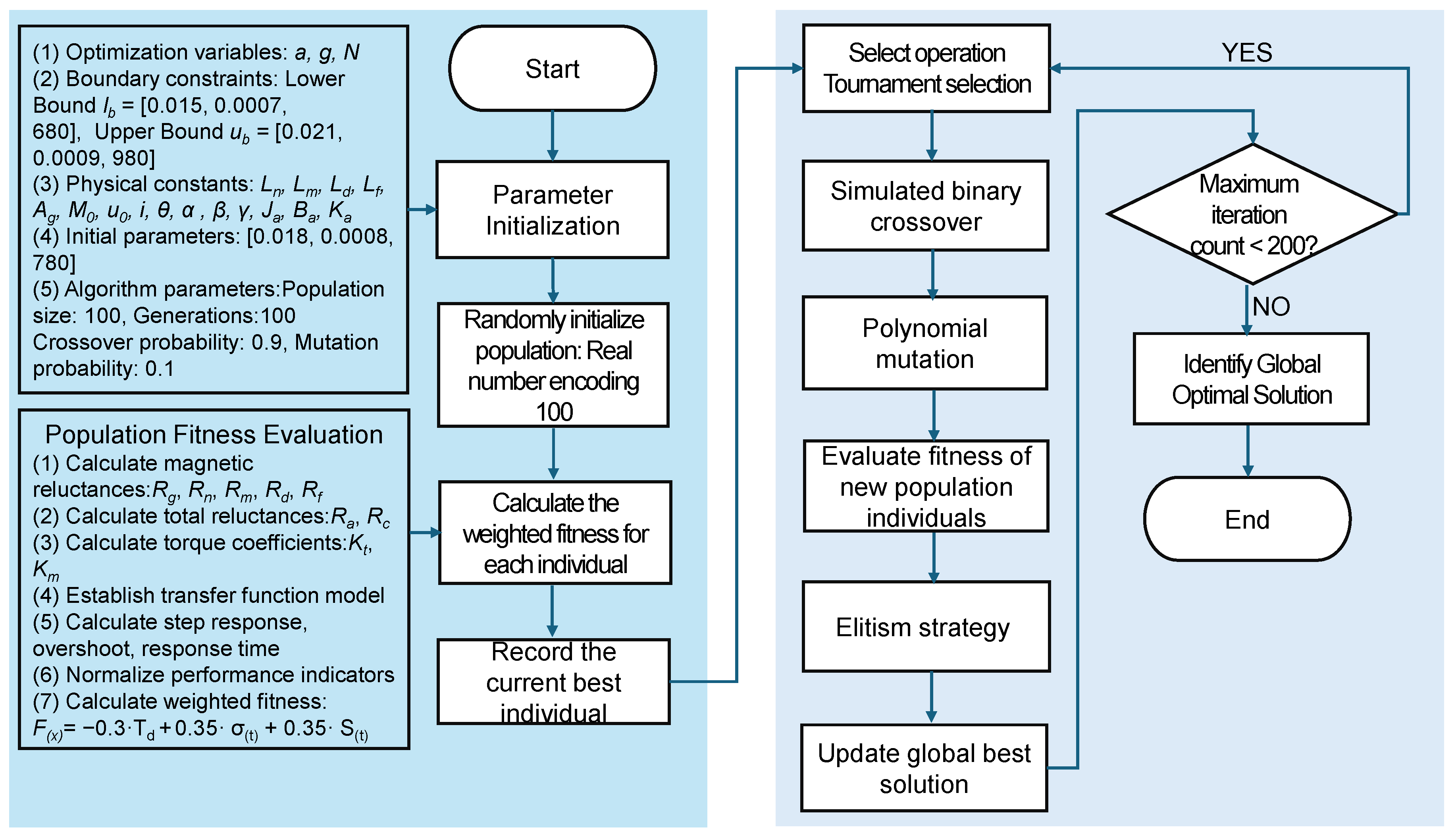
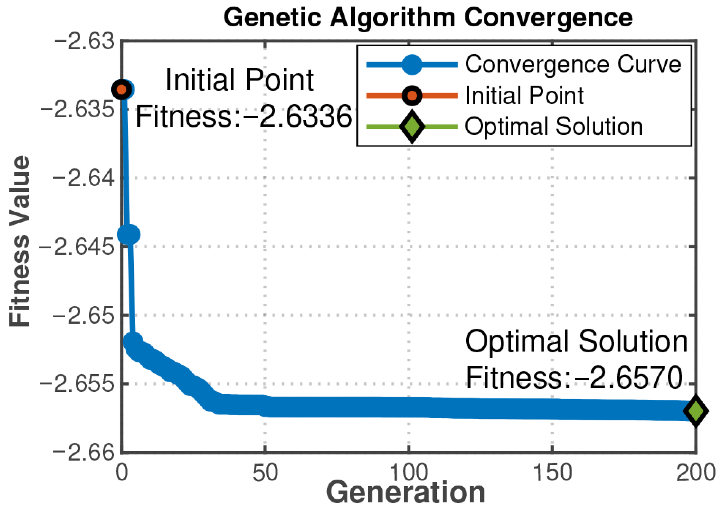
To prioritize dynamic performance optimization, the objective function weights are assigned based on engineering experience: 30% for output torque, 35% for overshoot, and 35% for response time [30]. Although alternative weighting schemes are considered, the selected values reflect a deliberate prioritization of system stability and response speed. The GA is configured with a population size of 100, a crossover probability of 0.9, a mutation probability of 0.1, and 200 iterations to ensure convergence efficiency without excessive computational cost. The genetic algorithm follows a standard procedure, illustrated in Figure 9, and employs tournament selection, simulated binary crossover, and polynomial mutation to effectively explore the solution space. An elitism strategy ensures that solution quality is maintained across generations. Convergence is achieved after 200 generations, with the fitness value improving rapidly before stabilizing at the global optimum, as shown in Figure 10.
The fitness value quantifies the quality of each individual in the GA. Typically, an iterative optimization process is employed by the GA to find individuals with better fitness values. The objective function is to find the minimum value of F(x). The decrease in the fitness values indicates that the optimization is successful. The optimized parameters are listed in Table 2.

4.2. Simulation Analysis of Optimization

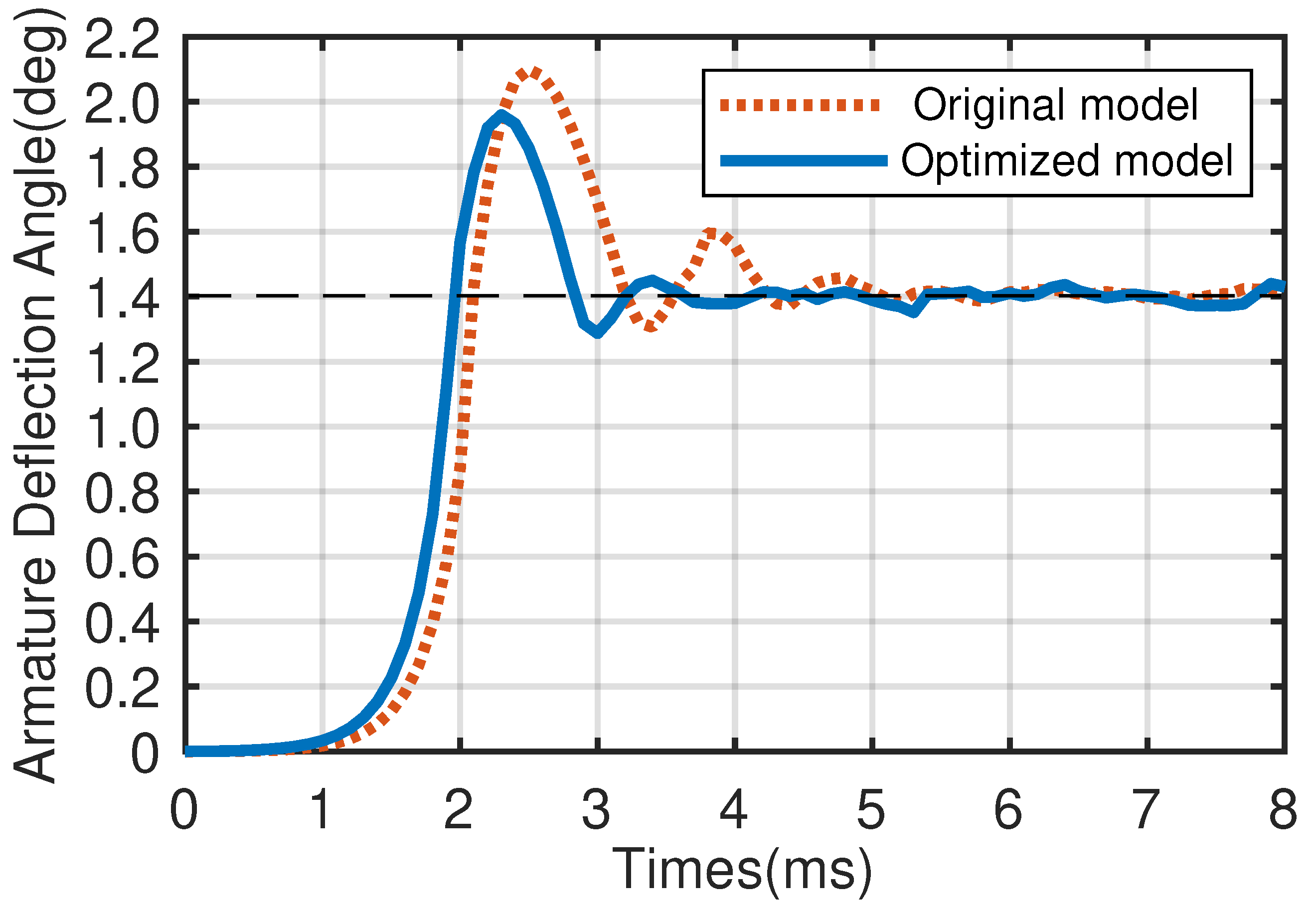
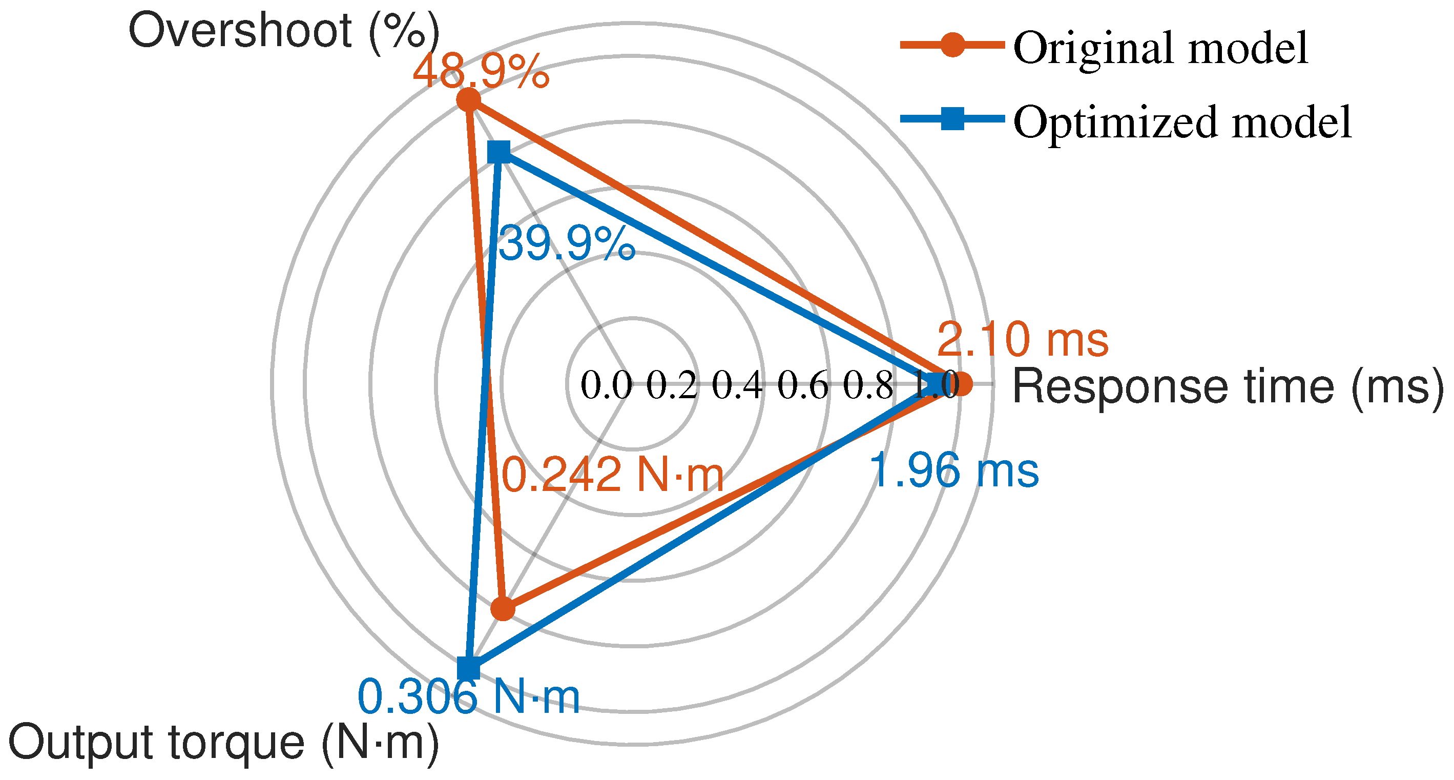
The performance is evaluated using FEA on the optimized model, and the results are subsequently compared with those of the original design, as shown in Figure 11 and Figure 12.
After optimization, the response time is reduced by 0.14 ms compared to the original model. The millisecond-level improvement enhances the system’s dynamic response in high-speed precision applications. Additionally, the overshoot is reduced by 9%. This result indicates that the proposed method effectively suppresses the excessive dynamic response and allows the motor output to reach a steady state more rapidly. Furthermore, the output torque increased to 0.306 N·m, reflecting a 26.4% improvement over the original model. These optimization results demonstrate that the system meets the stringent performance requirements for high precision, stability, and load capacity of torque motors used in precision servo control and micromachine drive applications.

5. Influence of Optimization on the Valve

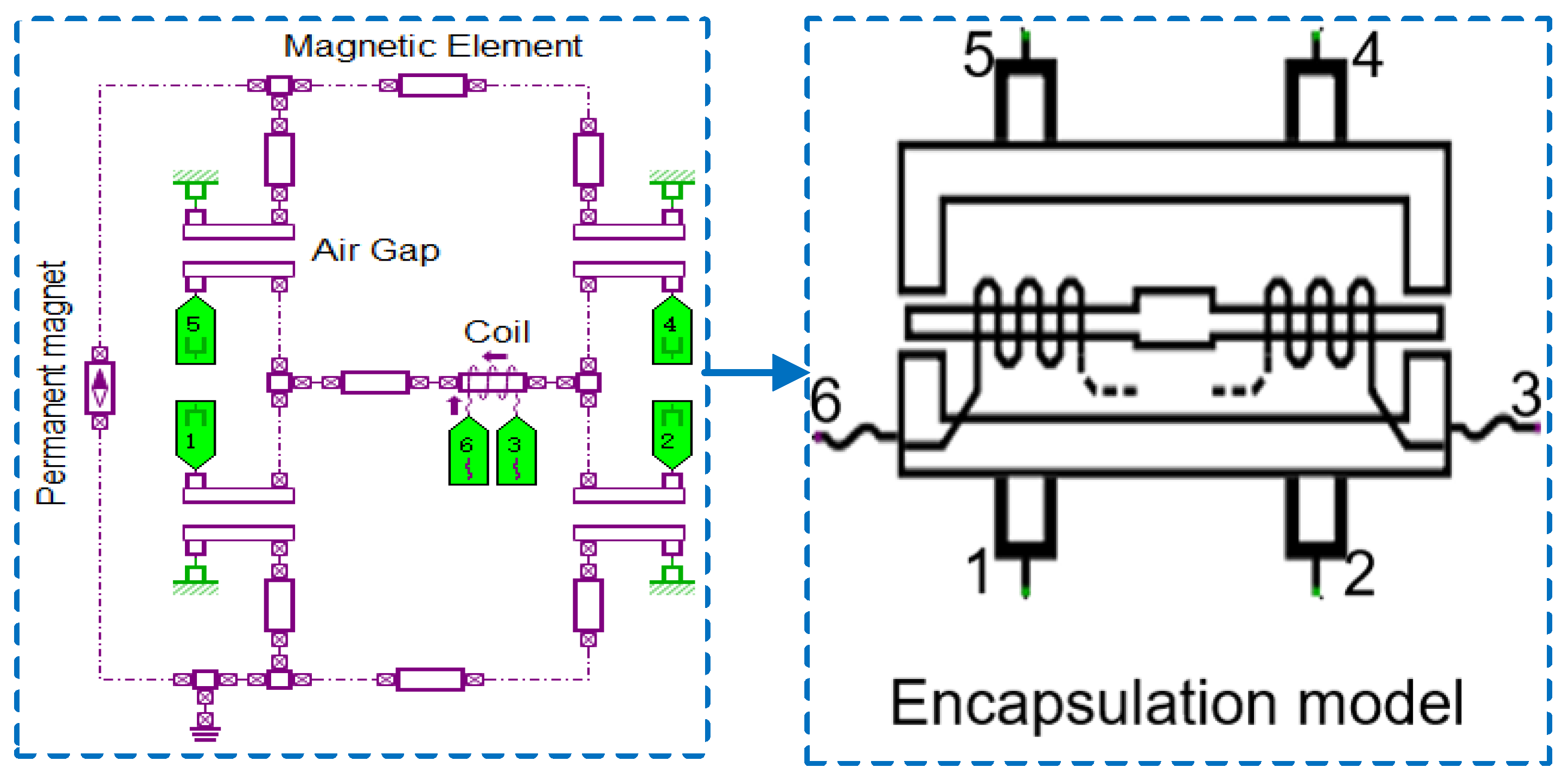
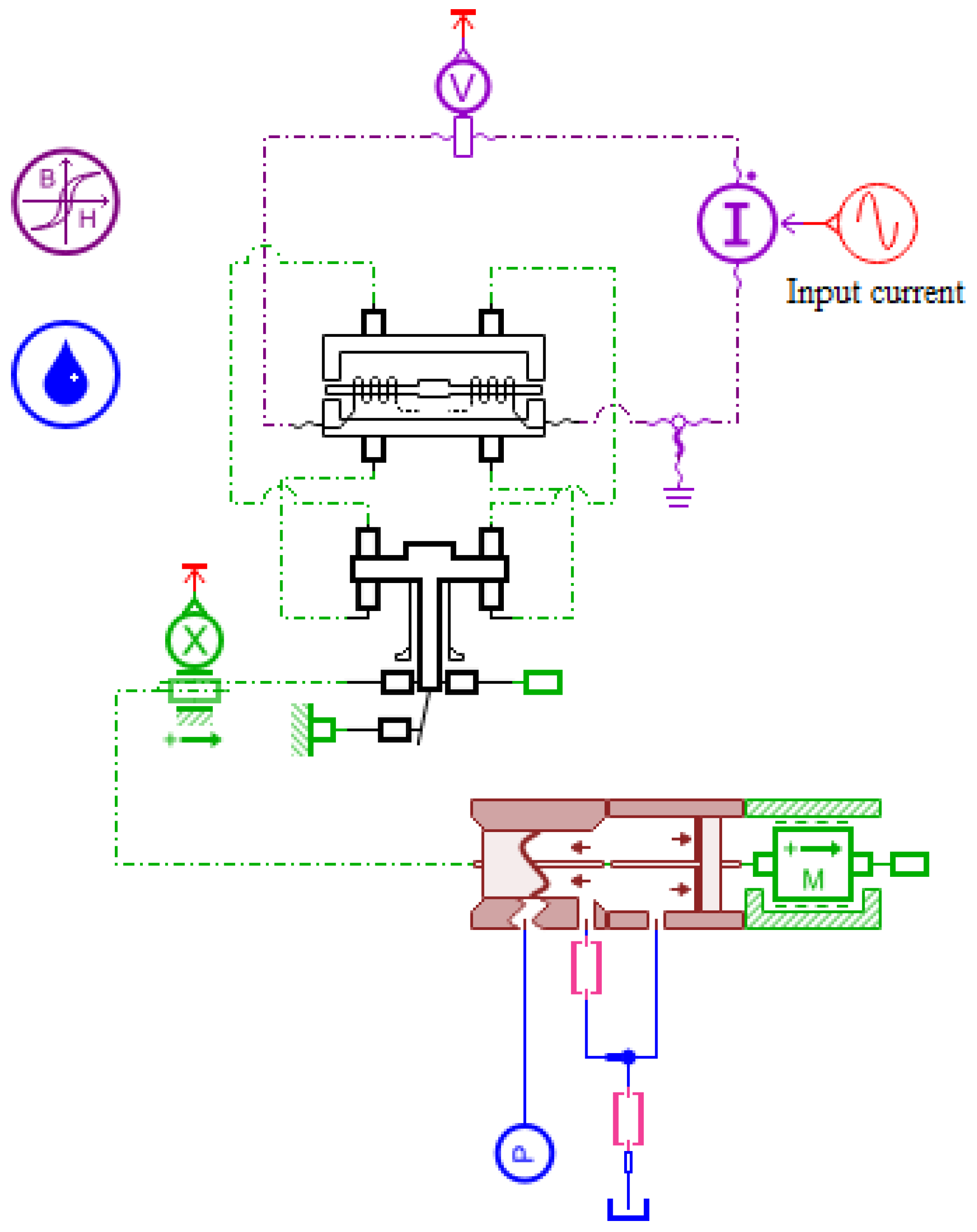
An integrated simulation model is established on the AMESim platform to systematically evaluate the improvement in flow gain of the direct-drive slide knife gate valve. The whole valve model incorporates an encapsulated torque motor submodel, as illustrated in Figure A1 and Figure A2 in Appendix A. The influence of the torque motor before and after optimization on the flow characteristics of the whole valve is compared. The main simulation parameters for each component in the model are shown in Table A1 of the Appendix A.
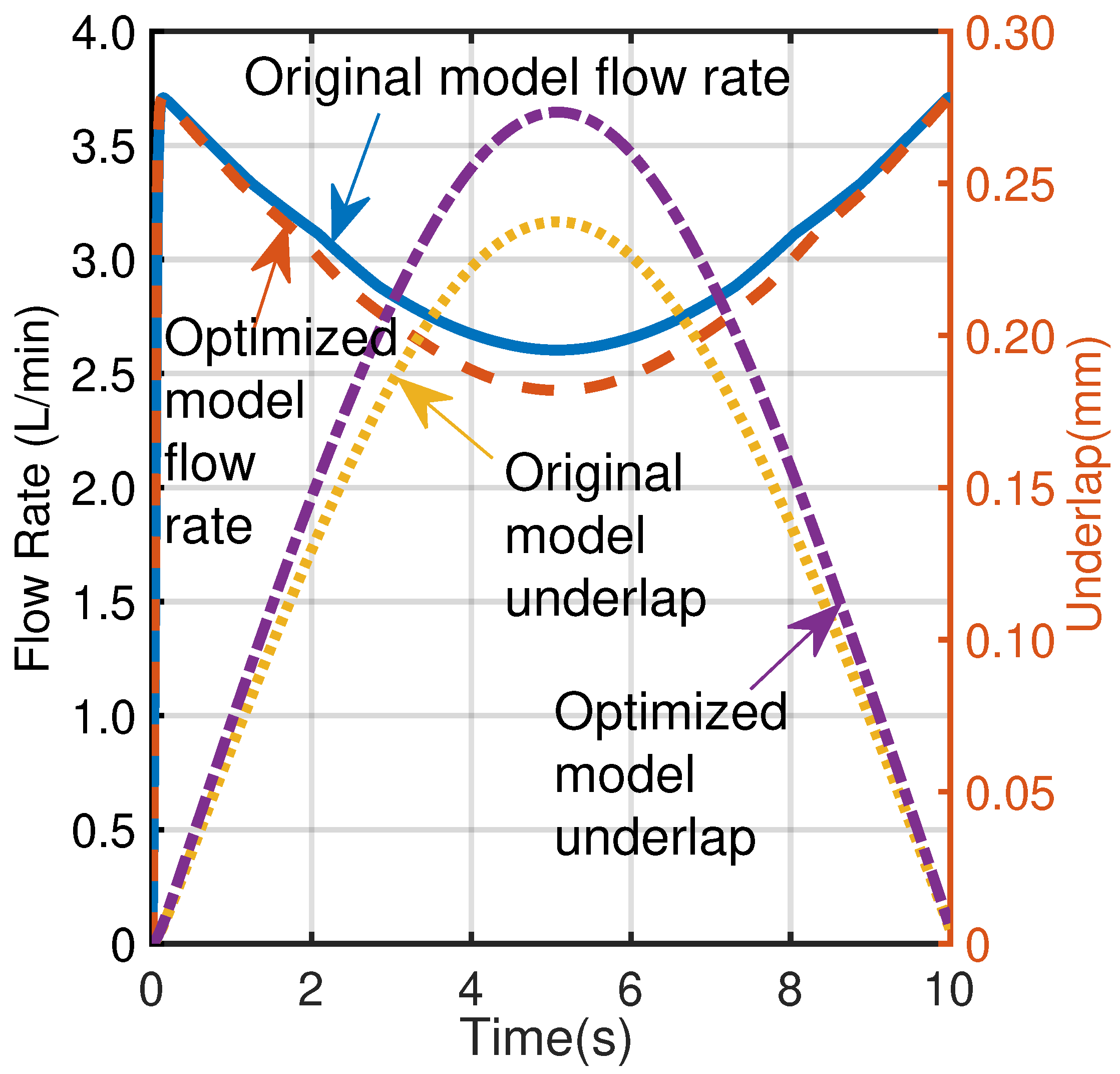
The transient flow characteristics after torque motor optimization are investigated in this paper. Under a sinusoidal input current of 0.05 A at 0.05 Hz and a pressure of 402 kPa, the flow rate and underlap are presented in Figure 13. Post-optimization, a significant enhancement in flow stability is observed. The flow rate of the optimized model is markedly smoother, with the oscillation amplitude substantially reduced compared to the original model, which exhibited minor oscillations during the initial 2 s and the subsequent 8 s. Concurrently, the dynamic response speed of the valve is greatly improved, with the time required to reach the steady-state flow reduced from 3.5 s to 1.8 s, representing a 48% improvement. Furthermore, by increasing the underlap from 0.23 mm to 0.27 mm in the optimized model, the internal leakage and associated energy losses are effectively suppressed. This adjustment results in a reduction in the steady-state flow rate from 2.60 L/min to 2.42 L/min—a 7.4% decrease—a strategic trade-off that significantly enhances control precision and energy efficiency.
The flow gain at 402 kPa and 598 kPa before and after optimization is presented in Figure 14. Comparing the curves of the same model under different pressures, in the original model, the average decrease rates are 2.27% and 2.38% at 402 kPa and 598 kPa, respectively. For the optimized model, the average decrease rates are 2.39% and 2.96%. This indicates that a higher pressure leads to a faster rate of flow decrease with increasing input current. At the same pressure, the flow rates of the optimized and original models are similar in both the low-current range (0–30 mA) and the high-current range (120–150 mA). In the high-current range, the flow rate stabilizes at 0.54 L/min, and a steady-state range without fluctuations is observed after optimization. In the medium-to-high-current range (40–110 mA), the flow rate decline in the optimized model is significantly greater than in the original model. Furthermore, the fluctuations in the optimized model at 598 kPa are more substantial, demonstrating that the optimization renders the flow control more sensitive under higher pressure differentials.
The flow rates are generally lower after optimization because the motor produces greater torque, which enhances the displacement and transition velocity of the slide knife gate. Although the steady-state flow is slightly reduced, the faster dynamic response leads to a higher effective flow rate per unit time. This reduction in flow becomes more pronounced at 598 kPa, indicating that the system exhibits greater sensitivity to parameter adjustments under higher pressure differentials. The optimized torque motor ensures reliable actuation of the slide knife gate even under low-current conditions, while maintaining stable performance in high-current scenarios with reduced susceptibility to pressure fluctuations.

6. Experimental Verifications

6.1. Static Test

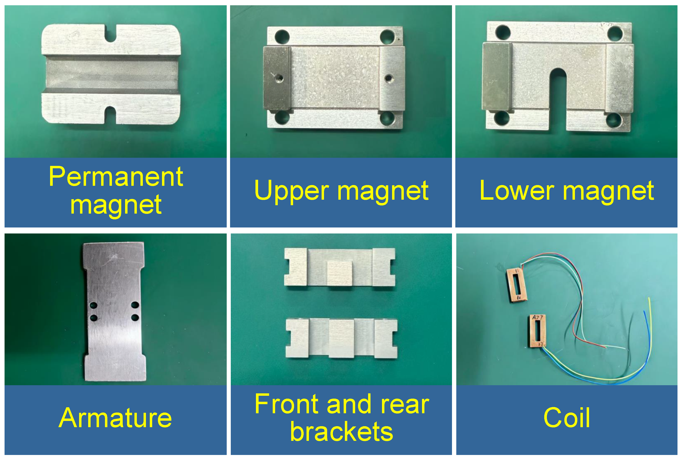
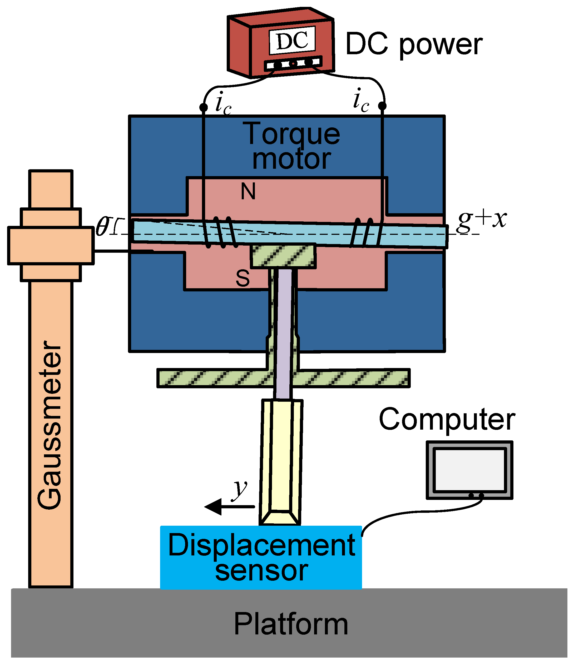
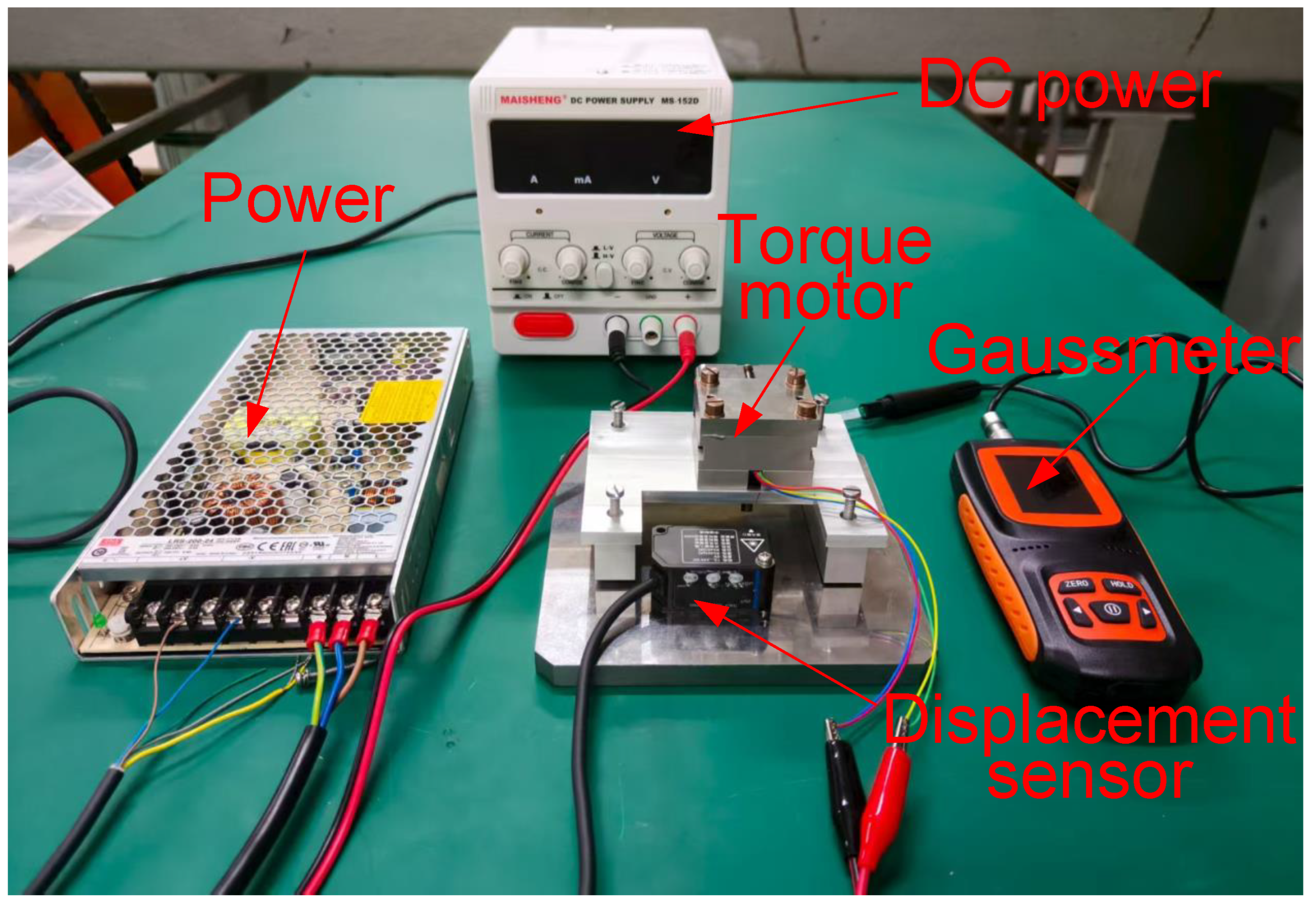
A prototype is built to the optimized dimensions, and a test rig is assembled to validate the simulation accuracy and the feasibility of the optimization. The key components of the optimized torque motor are presented in Figure 15, the schematic diagram of the test rig is shown in Figure 16, and the physical experimental setup is provided in Figure 17.
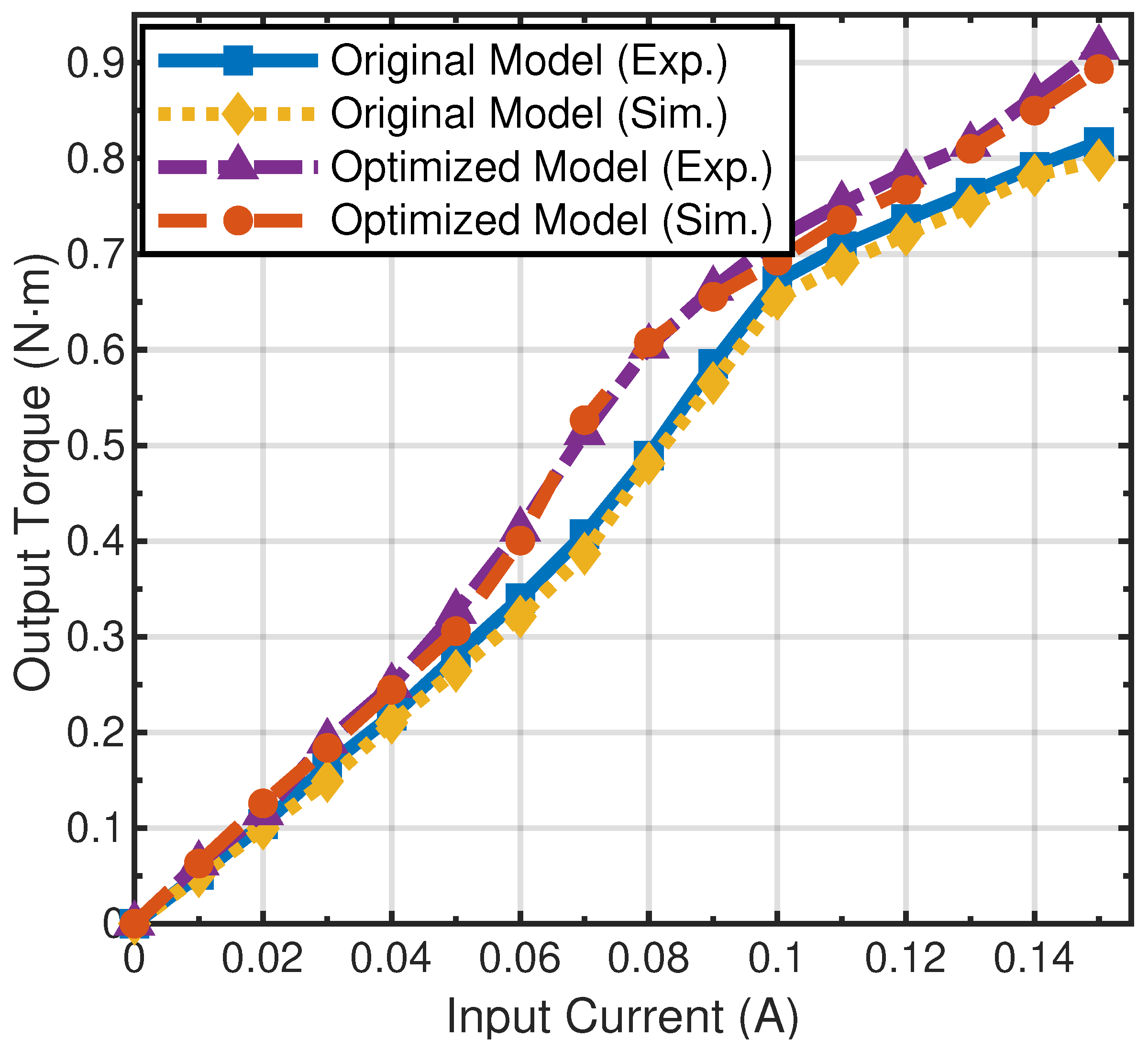
The output torque is measured under gradually increasing current, increased in steps of 0.01 A from 0 to 0.15 A. A comparison between the simulated results and the experimentally measured torque is presented in Figure 18.
The experimental results demonstrate that under operating conditions, the optimized torque motor exhibits significantly improved output torque, particularly in high-current regions. For example, when the input current is 0.07 A, a 26% increase in output torque is observed, with the torque increasing from 0.407 N·m to 0.513 N·m. This indicates that the model’s robustness and output performance have been enhanced, making it more suitable for high-load applications.
It can be observed that the discrepancy between the simulation results and the experimental data is minimal. The original model had a maximum deviation of 10% between simulation and experimental results, with an average error of 3.8%. The optimized model showed a maximum deviation of 8%, and the average error was 1.2%. The residual discrepancies primarily originate from magnetic circuit asymmetry, which is caused by assembly tolerances and magnetic flux deterioration due to coil thermal effects. The strong agreement between simulation and experimental results confirms the validity of the modeling approach and the reliability of the optimized design.

6.2. Dynamic Test

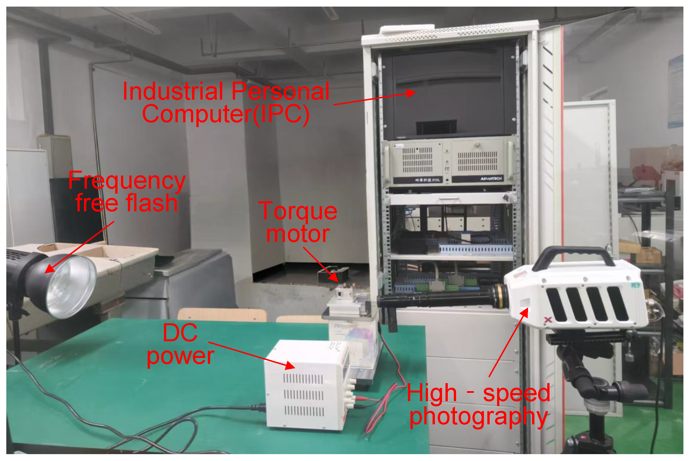
To comprehensively evaluate the optimized torque motor under a broader range of operating conditions, dynamic response tests were conducted on the torque motor. During the experiment, the high-speed camera used was the Revealer X213M. The high-speed camera shooting speed is configured to capture 13,600 frames per second, while maintaining a resolution of 1280 × 1024. Additionally, it utilizes a microscopic magnifying lens with a magnification capacity of 14 times. Capturing the deflection process of the torque motor armature assembly and calculate the response time necessitates high-intensity lighting. Therefore, the light source uses high-power LED. The test rig is seen in Figure 19.
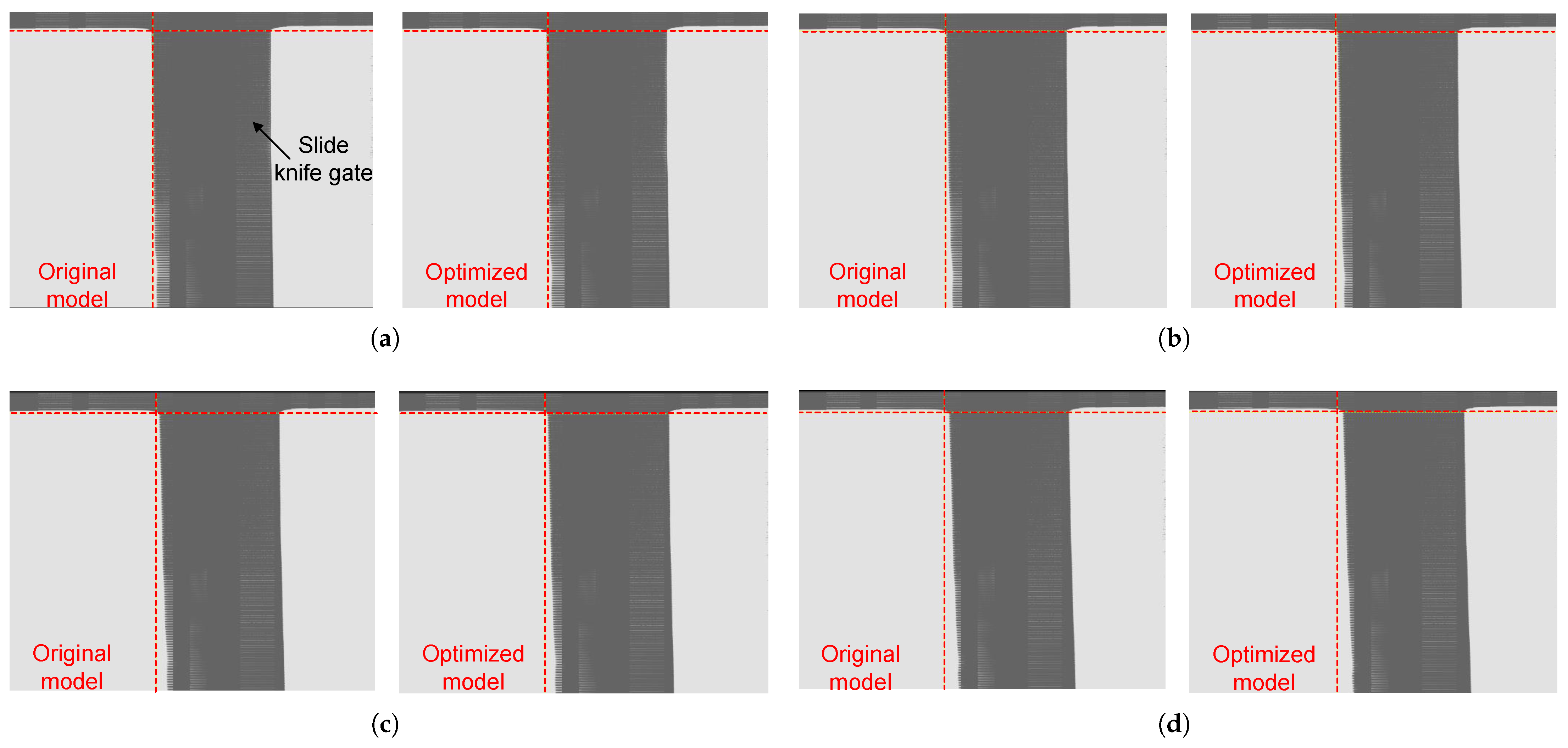
The input current signals are 0.05 A, 0.1 A, 0.15 A, and each set of experiments is repeated six times, and the average value is taken to reduce the random error. Comparing the model before and after optimization in terms of dynamic response, the deflection angle when stabilized at three sets of currents captured by a high-speed camera is shown in Figure 20, and the dynamic response time is calculated directly from the high-speed camera data by multiplying the number of frames between the trigger and the 90% steady-state position by the reciprocal of the frame rate (1/frame rate). The resulting response time data is presented in Table 3.
The response time of the torque motor is tested under various operating conditions, revealing that the optimized model exhibited a reduction in the average response time of 0.14 ms compared to the original model. This result validates the accuracy of the simulation and demonstrates the effectiveness of the optimization approach in enhancing the system’s dynamic response speed. Both the original and optimized models exhibit a monotonically decreasing response time with an increase in the input current. This trend is attributed to the fact that a larger control current generates a greater electromagnetic force, thereby effectively reducing the mechanical response delay of the torque motor. The optimized model achieves an average response time improvement of approximately 7.1%. This quantifiable enhancement holds significant engineering value for high-frequency, high-precision servo control applications.

7. Conclusions

To enhance the dynamic and static characteristics of the torque motor, the GA was employed to optimize its structural parameters. The conclusions are drawn as follows:
(1)
Based on FEA results, this paper reveals that the structural parameters of the torque motor are inherently coupled with its static and dynamic performance, where improving one metric often compromises others. Thus, torque motor design is inherently a multi-objective optimization problem requiring systematic trade-offs among output torque, response time, and overshoot.
(2)
The multi-objective GA is used to optimize the torque arm, air gap, and coil turns, resulting in a 20 mm arm, a 0.71 mm gap, and 980 turns. The output torque increases by 26.4%, the overshoot is reduced by 9%, and the response time decreases by 0.14 ms. Significant effectiveness is achieved.
(3)
AMESim simulations show that the optimized torque motors improve valve control precision and response speed, which accelerates the stabilization of flow rate. Consistent flow output is observed in high-current regions, suggesting reduced sensitivity to pressure fluctuations.
(4)
Experimental results conclusively demonstrate that the optimized model significantly enhances both the static and dynamic characteristics of the torque motor, quantified by a 26% increase in output torque and an average 7.1% reduction in response time. The strong agreement between the experimental data and simulation results further validates the accuracy of the theoretical models. Consequently, this paper provides insights into the design of torque motors for aerospace servo valves and the optimization of high-frequency servo valve performance.
This study focuses on the static and dynamic characteristics of the torque motor. A set of fixed weight coefficients is used to convert the multi-objective problem into a single-objective problem. This approach is effective for prioritizing current performance. Future work can concentrate on applying multi-objective algorithms such as NSGA-II, systematically exploring the Pareto optimal solution sets under different weight schemes. This will enable the most appropriate choice to be made based on different application scenarios.

Author Contributions

Conceptualization, J.Z. and Z.H.; methodology, J.S.; software, Q.L.; validation, Q.L., W.S. and J.Z.; formal analysis, B.Y.; investigation, J.Z.; resources, J.Z.; data curation, Q.L.; writing—original draft preparation, Q.L.; writing—review and editing, J.Z. and Z.H.; visualization, J.S.; supervision, W.S.; project administration, J.Z.; funding acquisition, J.Z. All authors have read and agreed to the published version of the manuscript.

Funding

This work was supported by the Provincial Key Research and Development Program in Heilongjiang of China (GZ20220097) and the Harbin Manufacturing Industry Technology Innovation Talent Program of China (CXRC20221104079).

Institutional Review Board Statement

Not applicable.

Informed Consent Statement

Not applicable.

Data Availability Statement

The raw data supporting the conclusions of this article will be made available by the authors on request.

Conflicts of Interest

The authors declare no conflicts of interest.

Abbreviations

The following abbreviations are used in this manuscript:
φ 1 Magnetic flux in air gap 1
φ 2 Magnetic flux in air gap 2
φ 3 Magnetic flux in air gap 3
φ 4 Magnetic flux in air gap 4
φ 5 Magnetic flux in the upper iron block
φ 6 Magnetic flux in the control coil
φ 7 Magnetic flux in the lower iron block
φ 8 Magnetic flux in the permanent magnet
φ 9 Magnetic flux in the permanent magnet
M 0 Permanent magnet
NNumber of turns in the control coil
R g 1 Reluctance of air gap 1
R g 2 Reluctance of air gap 2
R g 3 Reluctance of air gap 3
R g 4 Reluctance of air gap 4
R m Reluctance of the permanent magnet
R d Reluctance of the armature
R f Horizontal reluctance of the magnetic conductor
R n Vertical reluctance of the magnetic conductor
R m Reluctance of the leakage flux path in permanent magnet
R d Reluctance of the leakage flux path in the control coil
R g Reluctance of the leakage flux path in air gap
α Leakage coefficient of the permanent magnet
β Leakage coefficient of the coil
γ Leakage coefficient of the air gap

Appendix A

Figure A1. Torque motor model.
Actuators 14 00527 g0a1
Figure A2. Integrated valve model.
Actuators 14 00527 g0a2
Table A1. AMESim simulation parameters.
ParameterValue
Hydraulic oil density (kg/m3)778
Initial air gap (mm)0.8
Magnetic induction (T)0.15
Minimum coercive field (A/m)−20,000
Spool mass (g)3.5
Coil turns (turns)780
Moment of inertia (kg·m2) 5.8 × 10 7
Spring rate of feedback spring (N/m)3400
Inlet pressure (MPa)0.402/0.598
Armature assembly rotational damping (N·m/(rad/s))0.002
Armature assembly translational damping (N·s/m)10

References

  1. Deng, X. Modeling and Simulation Research of Fuel Metering Device Based on Rotary Direct Drive Valve. Master’s Thesis, University of Chinese Academy of Sciences, Beijing, China, 2020. [Google Scholar]
  2. Mi, J. Life Prediction Method of Direct-Drive Electro-Hydraulic Servo Valve Spool Valve Sleeve. Master’s Thesis, Chongqing University, Chongqing, China, 2023. [Google Scholar]
  3. Tu, F.; Shi, L.; Li, S.; Chen, C.; Wei, S.; Su, Z.; Wei, J. Research progress of direct drive electro-hydraulic servo valve. Fluid Mach. 2022, 50, 61–70. [Google Scholar]
  4. Huh, J.Y.; Park, C.S. An Analysis of Static and Dynamic Characteristics of Torque Motor. J. Drive Control 2015, 12, 9–14. [Google Scholar] [CrossRef]
  5. Manring, N.D.; Fales, R.C. Hydraulic Control Systems; John Wiley & Sons: Hoboken, NJ, USA, 2019. [Google Scholar]
  6. Wang, M.; Li, D.; Qu, R. An overview on developments and research of limited angle torque motor. Trans. China Electrotech. Soc. 2023, 38, 1486–1505. [Google Scholar]
  7. Wang, Z.; Li, J.; Hu, C.; Li, X.; Zhu, Y. Hybrid energy storage system and management strategy for motor drive with high torque overload. J. Energy Storage 2024, 75, 109432. [Google Scholar] [CrossRef]
  8. Zhang, Q.; Yan, L.; Duan, Z.; Jiao, Z.; Gerada, C.; Chen, I.-M. High torque density torque motor with hybrid magnetization pole arrays for jet pipe servo valve. IEEE Trans. Ind. Electron. 2019, 67, 2133–2142. [Google Scholar] [CrossRef]
  9. Yan, L.; Zhang, Q.; Duan, Z.; Jiao, Z. Modeling and analysis of servo valve torque motor based on FEM. In Proceedings of the 2017 IEEE International Conference on Cybernetics and Intelligent Systems (CIS) and IEEE Conference on Robotics, Automation and Mechatronics (RAM), Ningbo, China, 19–21 November 2017; pp. 791–796. [Google Scholar]
  10. Rao, D. Analysis of Influencing Factors of Output Torque on Fuel-Oil Servo Valve Torque Motor. Ph.D. Thesis, Yanshan University, Qinhuangdao, China, 2025. [Google Scholar]
  11. Hao, Z.; Ma, Y.; Wang, P.; Luo, G.; Chen, Y. A review of axial-flux permanent-magnet motors: Topological structures, design, optimization and control techniques. Machines 2022, 10, 1178. [Google Scholar] [CrossRef]
  12. Sharan, A.S.; Hiremath, S.S.; Venkatesha, C.S.; Venkatesha, C.S. Investigation on the critical parameters affecting the working design dynamics of a torque motor employed in an electro-hydraulic servovalve. Simulation 2019, 95, 31–49. [Google Scholar]
  13. Sun, X.; Xu, N.; Yao, M. Sequential subspace optimization design of a dual three-phase permanent magnet synchronous hub motor based on NSGA III. IEEE Trans. Transp. Electrif. 2023, 9, 622–630. [Google Scholar] [CrossRef]
  14. Sun, X.; Hu, C.; Lei, G.; Guo, Y.; Zhu, J. State feedback control for a PM hub motor based on gray wolf optimization algorithm. IEEE Trans. Power Electron. 2020, 35, 1136–1146. [Google Scholar] [CrossRef]
  15. Tian, W.; Zhang, C.; Mao, Z.; Cheng, B. Optimization of a dual-channel water-cooling heat dissipation system for PMSM in underwater unmanned vehicles using a multi-objective genetic algorithm. J. Mar. Sci. Eng. 2024, 12, 2133. [Google Scholar] [CrossRef]
  16. Oh, J.-A.; Sarbajit, P.; Kim, D.-J.; Bang, D.; Lee, K.-W.; Yoon, B.-K.; Jang, G.-W.; Kang, J.-H.; Chang, J. Design and performance testing of a large direct-drive generator for low speed and high torque applications. J. Mech. Sci. Technol. 2025, 39, 1641–1651. [Google Scholar] [CrossRef]
  17. Xie, F.; Wang, H.; Ni, S.; Xu, J.; Zheng, Z. Multi-objective optimization design of external rotor permanent magnet synchronous motor for robot arm. J. Mech. Sci. Technol. 2024, 38, 803–814. [Google Scholar] [CrossRef]
  18. Salarian, M.; Azari, M.N.; Hajiaghaee-Keshteli, M. Using multi-objective optimization and finite element method to reduce cogging torque in a brushless DC motor. IETE J. Res. 2024, 70, 6350–6360. [Google Scholar] [CrossRef]
  19. Chai, J.; Zhao, T.; Gui, X. Multi-objective optimization design of permanent magnet torque motor. World Electr. Veh. J. 2021, 12, 131. [Google Scholar] [CrossRef]
  20. Cen, Y.; Shen, H.; Wang, X.; Wu, Y.; Du, J. Multi-objective optimization analysis of electromagnetic performance of permanent magnet synchronous motors based on the PSO algorithm. Energies 2024, 17, 4637. [Google Scholar] [CrossRef]
  21. Ni, X.; Li, Y.; Sun, R.; Xu, Y. Multiparameter optimization analysis of permanent magnet couplings using response surface methodology and genetic algorithm. J. Mech. Sci. Technol. 2024, 38, 6279–6286. [Google Scholar] [CrossRef]
  22. Zhang, J.; Shan, W.; Chen, K.; Chen, Y. Research and optimization of demagnetization performance of permanent magnet synchronous motorized spindle. Mach. Tool Hydraul. 2025, 53, 24–31. [Google Scholar]
  23. Feng, L.; Liu, W.; Ding, Y.; Li, H. Optimal design and analysis of high-speed permanent magnet synchronous motor based on genetic algorithm and TOPSIS method. J. Electr. Eng. Technol. 2025, 20, 1463–1473. [Google Scholar] [CrossRef]
  24. Fan, D.; Quan, L.; Zhu, X.; Xiang, Z. Design and optimization of double-stator Vernier permanent magnet motor with improved torque characteristics based on flux modulation theory. IEEE Trans. Magn. 2022, 58, 8202707. [Google Scholar] [CrossRef]
  25. Stosiak, M.; Lubecki, M.; Karpenko, M. Designing a Composite Hydraulic Cylinder Using Genetic Algorithms. Actuators 2025, 14, 77. [Google Scholar] [CrossRef]
  26. Li, Y. Modeling and Simulink Simulation of Electrohydraulic Servo Valve; Mechanical Industry Press: Beijing, China, 2020. [Google Scholar]
  27. Li, H. Hydraulic Control Systems; National Defense Industry Press: Beijing, China, 1990. [Google Scholar]
  28. Katoch, S.; Chauhan, S.S.; Kumar, V. A review on genetic algorithm: Past, present, and future. Multimed. Tools Appl. 2021, 80, 8091–8126. [Google Scholar] [CrossRef] [PubMed]
  29. Qiu, F.Y.; Mo, L.P.; Jiang, B.; Wang, L.P. Multi-Objective particle swarm optimization algorithm using large scale variable decomposition. Chin. J. Comput. 2016, 39, 2598–2613. [Google Scholar]
  30. Chen, J. Dynamic Simulation and Optimal Design and Control Method of Jet Pipe Servo Valve. Ph.D. Thesis, Northwestern Polytechnical University, Xi’an, China, 2017. [Google Scholar]
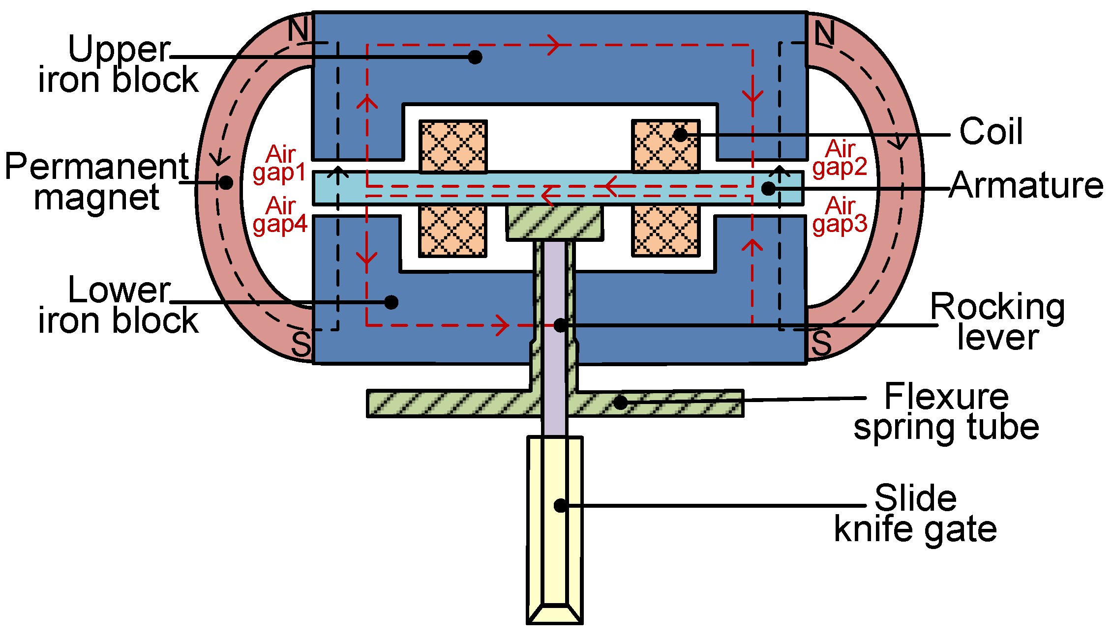
Figure 1. Operating principle of the torque motor.
Actuators 14 00527 g001
Figure 2. Equivalent magnetic circuit model of the torque motor.
Actuators 14 00527 g002
Figure 3. Schematic of armature deflection.
Actuators 14 00527 g003
Figure 4. Schematic diagram of the force analysis of the armature assembly.
Actuators 14 00527 g004
Figure 5. Simulation model.
Actuators 14 00527 g005
Figure 6. Influence of the air gap on the torque motor performance: (a) Deflection angle. (b) Output torque.
Actuators 14 00527 g006
Figure 7. Influence of the coil turns on the torque motor performance: (a) Deflection angle. (b) Output torque.
Actuators 14 00527 g007
Figure 8. Influence of the torque arm on the torque motor performance. (a) Deflection angle. (b) Output torque.
Actuators 14 00527 g008
Figure 9. GA flowchart.
Actuators 14 00527 g009
Figure 10. Iterative convergence curve.
Actuators 14 00527 g010
Figure 11. Transient response comparison.
Actuators 14 00527 g011
Figure 12. Performance comparison.
Actuators 14 00527 g012
Figure 13. Comparison of flow rate and underlap between the original model and the optimized model.
Actuators 14 00527 g013
Figure 14. Comparison of flow gain between the original model and the optimized model.
Actuators 14 00527 g014
Figure 15. Torque motor components.
Actuators 14 00527 g015
Figure 16. Schematic of the test rig.
Actuators 14 00527 g016
Figure 17. Static test rig.
Actuators 14 00527 g017
Figure 18. Comparison of output torque between simulation and experimental results.
Actuators 14 00527 g018
Figure 19. Dynamic test rig.
Actuators 14 00527 g019
Figure 20. Comparison of armature deflection angles before and after optimization. (a) 0 mA; (b) 50 mA; (c) 100 mA; and (d) 150 mA.
Actuators 14 00527 g020
Table 1. Parameters of the torque motor.
ParameterInitial ValueVariable Range
Torque arm (mm)1815–21
Air gap (mm)0.80.7–0.9
Coil turns (turns)780600–1000
Table 2. Optimization results.
ParameterOptimized Value
Torque arm (mm)20
Air gap (mm)0.71
Coil turns (N)980
Table 3. Comparison of dynamic response time.
Input Current (A)ModelResponse Time (ms)
0.05Original2.12
Optimized1.96
0.10Original2.09
Optimized1.94
0.15Original2.05
Optimized1.93
Disclaimer/Publisher’s Note: The statements, opinions and data contained in all publications are solely those of the individual author(s) and contributor(s) and not of MDPI and/or the editor(s). MDPI and/or the editor(s) disclaim responsibility for any injury to people or property resulting from any ideas, methods, instructions or products referred to in the content.