Article

Nonlinear Dynamic Modeling of Flexible Cable in Overhead Bridge Crane and Trajectory Optimization Under Full-Constraint Conditions

by
Guangwei Yang
1,
Jiayang Wu
1,
Yutian Lei
2,
Yanan Cui
1,
Yifei Liu
3,
Lin Wan
4,
Gang Li
3,
Chunyan Long
5,6,
Yonglong Zhang
2,* and
Zehua Chen
4,*
1
College of Mechanical Engineering, Taiyuan University of Technology, Taiyuan 030024, China
2
College of Aeronautics and Astronautics, Taiyuan University of Technology, Taiyuan 030024, China
3
College of Electrical and Power Engineering, Taiyuan University of Technology, Taiyuan 030024, China
4
College of Artificial Intelligence, Taiyuan University of Technology, Taiyuan 030024, China
5
Shanxi Keda Automatic Control Co., Ltd., Taiyuan 030006, China
6
Provincial Technology Innovation Center for Special Robots in Mines, Taiyuan 030006, China
*
Authors to whom correspondence should be addressed.
Actuators 2025, 14(11), 513; https://doi.org/10.3390/act14110513
Submission received: 13 August 2025 / Revised: 11 October 2025 / Accepted: 21 October 2025 / Published: 23 October 2025
(This article belongs to the Special Issue Modeling and Nonlinear Control for Complex MIMO Mechatronic Systems)

Abstract

Gantry cranes play a key role in modern industrial logistics. However, the traditional dynamic model based on the assumption of cable rigidity faces difficulty in accurately describing the complex swing characteristics of flexible cables, resulting in low load positioning accuracy and limited operation efficiency. To address this problem, this paper proposes a cable modeling method that considers the flexible deformation and nonlinear dynamic characteristics of the cable. Based on the theory of continuum mechanics, a flexible cable dynamic model that can accurately describe the flexible deformation and distributed mass characteristics of the cable is established. In order to solve the transportation time optimization and full-state constraint problems, a velocity trajectory optimization algorithm based on a discretization framework is proposed. Through inverse kinematics analysis and numerical integration technology, a reverse angle enumeration reasoning (RAER) method is proposed to suppress the swing of the load. Under the same constraints of distance, velocity, acceleration, cable swing angle, and residual swing angle, RAER requires a longer transportation time but achieves smaller peak swing and residual swing, making it the only algorithm that satisfies full-state constraints. Under the energy criterion, the proposed algorithm also requires the least amount of energy. Comprehensive comparisons through simulations and experiments show that the predicted swing angles of the flexible cable are highly consistent with the experimental results.

1. Introduction

With the transformation and upgrading of the global automotive industry, new energy vehicles have shown broad development prospects. As the core component of new energy vehicles, the safety and stability of the battery pack will directly affect the vehicle’s range and operating efficiency. However, when replacing the battery pack, the under-driven characteristics of the crane system cause the cable speed to change, which in turn causes the load to swing. This not only increases the risk of damage to the battery pack but also reduces the efficiency and safety of battery replacement. In recent years, in response to this problem, researchers have explored cable anti-sway technology for gantry hoisting devices and proposed a series of effective control strategies to improve the safety and efficiency of battery replacement and ensure that the battery pack is intact during the battery replacement process.
To prevent cable swaying in the gantry hoisting system, achieving anti-sway through electronic control devices is the current mainstream method, and many scholars have proposed a variety of control strategies [1,2,3,4]. Input shaping is an open-loop control method that adds a specific pulse sequence to the input signal of the system to offset the inherent resonant frequency of the system [5], thereby reducing or eliminating the vibration of the system [6,7,8]. Input shaping techniques include Zero Vibration (ZV) [9] and Zero Vibration Derivative (ZVD) shapers [10,11], smoother shaping [12], positive and negative input shapers [13], finite-state input shaping [14], and extra intensive shapers. Singhose et al. achieved sway suppression of the crane via feedforward control with input shaping and used a tracker to follow the trolley and successfully generate the motion trajectory in the system [15]. However, input shaping is an open-loop control method. When the system deviates from the nominal value due to external interference, the performance of the open-loop control system will be greatly affected. Li et al. designed a PID controller tuned by Particle Swarm Optimization (PSO) and the Simulated Annealing (SA) algorithm [16] which significantly reduced swing angle stabilization time and the maximum swing angle, thereby improving system response speed and stability, achieving anti-sway, and improving the positioning accuracy of bridge cranes during operation. In the field of shipborne cranes, Sun et al. employed coordinate transformation to improve the stability of a nonlinear stabilizing control scheme under the original nonlinear model and proposed a dynamic feedback control method to eliminate payload swing using only measurable signals [17,18]. In addition, in the field of hydraulic loading cranes, Konrad et al. integrated the feedforward loop of the two-degree-of-freedom anti-sway controller and the electro-hydraulic motion controller [19], and experimentally proved that this configuration has good payload angle suppression capabilities. For the anti-sway control of bridge cranes in complex environments, Yu et al. studied and constructed a three-dimensional dynamic mathematical model [20], designing an anti-sway system using fuzzy control theory and validating its robustness through simulation analysis. In order to further enhance the robustness and adaptability of anti-sway control, Yi et al. also developed a new fuzzy controller based on the single-input rule module (SIRM) dynamically linked to the fuzzy inference model [21], achieving fast and smooth anti-sway and positioning control by adjusting the acceleration of the trolley, showing strong robustness and adaptability. In the double-pendulum dynamics problem, Wu et al. constructed a double-pendulum crane model with a distributed mass beam (DMB) [22], combined with the time optimal control trajectory and the oscillation suppression strategy, effectively controlling the vibration of the DMB. Li et al. proposed an anti-sway controller and developed an optimal trajectory planning strategy based on time polynomials which suppresses the undriven swing of a double-swing tower crane and solves the full-state constraint and obstacle avoidance problems [23,24]. Sun et al. proposed a novel amplitude-saturated output feedback (OFB) control method that incorporates virtual payloads and requires no velocity feedback, effectively achieving control of an underactuated double-pendulum crane [25,26]. Researchers have proposed an adaptive gain sliding mode control strategy to solve the load positioning problem of container ship cranes which successfully meets the dual needs of load positioning and anti-sway [27,28,29,30,31]. These feedback control methods improve robustness, but most studies still approximate the cable as a rigid link and do not simultaneously account for full-state constraints such as velocity, acceleration, and swing angle, which limits their applicability in practical overhead bridge crane scenarios. The above electronic anti-sway devices have ensured anti-sway control to a certain extent, but they are generally based on theoretical research on control and face difficulties in application to real-life scenarios.
The Rider Block Tagline system is a typical mechanical anti-sway method in anti-sway research. Based on this, researchers have developed a variety of mechanical anti-sway technologies and control strategies [32]. For example, the Active Rider Block Tagline System (ARBTS) reduces the need for boom operation caused by ship movement by controlling the movement of the tagline, significantly reduces the boom power and cable speed, and improves the operating range and efficiency of the crane. In addition, a dynamic analysis model based on a rigid–flexible coupling virtual prototype was proposed [33] which can accurately simulate the dynamic characteristics of offshore cranes, and its effectiveness was verified through experiments. The Multi-Cable Anti-Sway System (MCAS) reduces the swing amplitude of cargo by 85% through the synergy of multiple cables, significantly improving the lifting efficiency of offshore cranes [34]. The method based on Maryland locks is also a commonly used anti-sway method [35,36]. Kimiaghalam et al. used Maryland rigging to achieve complete control of cable length [37], thereby effectively suppressing swing. The results show that the scheme plays a certain role in ensuring anti-sway. These studies not only improve the working efficiency and safety of cranes but also provide an important theoretical and experimental basis for the future development of anti-sway technology. Nevertheless, existing mechanical anti-sway devices and equipment still face some challenges in practical applications. First, conventional overhead cranes approximate the flexible hoisting cable as a rigid link in their kinematic models, introducing appreciable errors in the predicted load trajectory. Second, when transport time minimization and full-state constraints are considered, current velocity profile optimization techniques offer only limited suppression of payload sway.
Existing flexible body modeling approaches fall into two main categories: lumped-mass/multi-segment rigid link models and finite-element/nonlinear rod formulations. The former are limited in representing higher-order modes and spatial curvature, while the latter, although exerting higher fidelity, incur substantial dimensionality and parameter burdens that hinder efficient integration into online trajectory optimization. Meanwhile, common optimization frameworks, such as input shaping, feedback control, and mechanical anti-sway devices, typically synthesize trajectories using displacement or velocity as the primary variables and tend to treat engineering constraints (velocity, acceleration, peak swing angle, residual swing) via soft penalties or post hoc adjustments, lacking guarantees of feasibility under hard constraints. Few studies simultaneously address flexible cable dynamics, geometric nonlinearity, and full-constraint trajectory optimization. To fill this gap, this study proposes an optimized cable structure kinematic model and an algorithm system for controlling the speed of dynamic inertia compensation of the cable swing angle. The optimized cable structure solves the problem of accurately predicting load motion trajectory in the gantry crane. A flexible cable model is established based on continuum mechanics, explicitly incorporating physical mechanisms such as distributed mass, bending stiffness, and damping. Building on this model, the RAER method is proposed, which ensures the upper limits of velocity, acceleration, swing angle, and residual swing angle within the same optimization framework through an angle–time discretization configuration and a constraint-aware search using reverse angle enumeration. Simulation and experiments demonstrate reduced peak swing and near-zero residual oscillation, confirming the effectiveness and novelty of the approach for coupled flexible dynamics and full-constraint trajectory optimization problems.
The main contributions of this study can be summarized as follows:
(1)
A nonlinear dynamic model of flexible cables in overhead bridge cranes is established based on continuum mechanics which accurately captures the distributed mass, bending stiffness, and damping effects that are often neglected in conventional rigid link models.
(2)
A novel trajectory optimization framework named reverse angle enumeration reasoning (RAER) is proposed. By discretizing the continuous dynamics and systematically enumerating candidate trajectories, RAER ensures full-state constraint satisfaction while effectively suppressing load swing.
(3)
The effectiveness and robustness of the proposed model and optimization strategy are validated through both numerical simulations and experiments on a self-built crane platform, demonstrating significant improvements in swing suppression and motion smoothness compared to existing methods. Compared with existing methods, the predicted and measured responses of the flexible cable exhibit high similarity. The RAER algorithm satisfies all state constraints while achieving the lowest energy consumption, and it provides significant improvements in swing suppression and motion smoothness.
The rest of this paper is organized as follows. Section 2 investigates the dynamics and motion trajectory modeling of the flexible cable system in a bridge crane. It then introduces the dynamic modeling of the flexible cable, along with an analysis of its internal forces and frictional forces. Section 3 focuses on the numerical discretization and dynamic optimization of the cable motion control system, proposing discretization schemes and trajectory planning methods and implementing dynamic optimization algorithms. Section 4 validates and analyzes the effectiveness of cable kinematics and velocity optimization through simulation and experiments. Finally, the conclusion of this work is drawn in Section 5.

2. Dynamics and Motion Trajectory Modeling of the Flexible Cable System in Bridge Cranes

This section explores the dynamic modeling and trajectory analysis of flexible cable systems in bridge cranes. It begins by introducing the dynamic modeling methods for flexible cables, followed by an analysis of the effects of internal forces and friction within the cables. The system’s dynamic model is analyzed from three aspects: geometric parameterization, continuum mechanics-based quantification, and dynamic equilibrium. This provides a theoretical foundation for accurately predicting the motion characteristics of the load and the flexible cable.

2.1. Dynamic Modeling of Flexible Cable

Traditional lifting systems generally simplify cables into rigid rods, ignoring their flexible deformation and nonlinear dynamic characteristics, making it difficult to accurately predict their swinging behavior in actual operations, causing the battery pack lifting trajectory to deviate from the expected path.
Starting from the nonlinear dynamic characteristics of the cable, this study constructs a mathematical model that is closer to reality, comprehensively considering its mass distribution, elastic deformation, and bending stiffness, using a multi-body dynamics simulation algorithm to simulate the swing amplitude and angle of the cable under different working conditions.
To derive the kinematic equations of the dynamic model of the flexible cable crane, this section first formulates the expressions for the distances from the origin to the cable’s lower end and to its centroid.
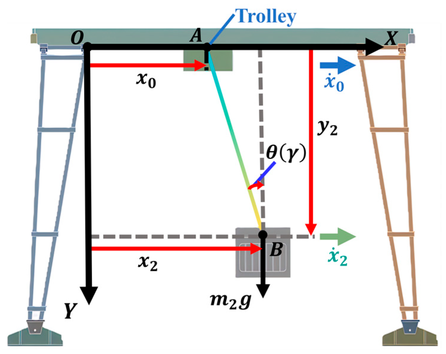
Figure 1 illustrates the schematic and dynamic models of the flexible cable crane hoisting system. As shown in Figure 1a, the truck battery pack is suspended from the bottom of the trolley by flexible cables, and the energy required by the trolley is provided by an electric motor.
It is stipulated that the horizontal rightward direction is defined as the positive x-axis, and the horizontal downward direction is defined as the positive y-axis. The symbol index of this paper is explained in Appendix A.1. The total length of the cable is L . At the beginning, the upper endpoint of the cable is at the origin; the cable coincides with the positive y-axis. At this time, the bending angle of the cable θ is recorded as 0°. The gravitational acceleration is g , and the gravitational acceleration is also along the positive y-axis. θ is defined as the angle between the tangent line at the lower endpoint of the cable and the positive direction of the y-axis, with the counterclockwise direction as the positive direction. When θ   >   0 , the cable deflects toward the negative x-axis. We assume that the cable does not stretch during the deformation process. The upper endpoint of the cable begins to move along the positive direction of the x-axis. The coordinate of the upper endpoint A of the cable is x 0 , y 0 , the centroid C coordinate of the cable is x 1 , y 1 , the coordinate of the lower endpoint B of the cable is x 2 , y 2 , and the value of θ is not greater than 90°.
The relationship between the amount of motion that changes with time is defined as follows:
θ = θ t ;   x 0 = x 0 t ;   y 0 = y 0 t ;   x 1 = x 1 t ;   x 2 = x 2 t ;   y 1 = y 1 t ;   y 2 = y 2 t
Figure 2 presents the force analysis of a cable segment at an arbitrary point located at a distance L i from the upper endpoint A. m 2 denotes the payload mass, Δ L is the unit length of the cable, A is the bending stiffness of the cable, Δ m 1   g is the gravitational force acting on a unit length of the cable, m 2 g + Δ m 1   L L i g is the tensile force acting on the cross-section at the upper endpoint of this unit cable, m 2 g + Δ m 1   L L i Δ L g is the tensile force acting on the cross-section at the lower endpoint of this unit cable, and A θ L is the bending moment applied to this unit cable.
To further determine the centroid position of the cable in the static circular arc state, it is necessary to clarify the spatial coordinate distribution of any point x ^ s , y ^ s in the bent state. This paper adopts the method of constant curvature and initial tangent angle to establish the coordinate expression based on the geometric differential relationship. Let the arc length parameter be s 0 , L , which represents the distance from the anchor point (the upper endpoint of the cable) downward along the cable length direction. The arc length of the upper endpoint of the cable is s = 0 , and the arc length of the lower endpoint is s = L . The curvature is κ   = θ L . In the direction of the arc length, the tangent angle changes uniformly. The initial tangent direction coincides with the positive direction of the y-axis, and the angle coinciding with the positive direction of the x-axis is α 0 = π 2 . After passing the arc length s , the tangent angle becomes as follows:
α s = π 2 + κ s = π 2 + θ L s
In differential form, the relationship between the projection of a small arc segment on the x-axis and y-axis, and the tangent angle can be expressed as follows:
d x d s = cos α s = sin θ L s d y d s = sin α s = cos θ L s
If we integrate the above differential equation from 0 to s and set the anchor point at the origin x ^ 0 , y ^ 0 = 0 , 0 , we can obtain the following:
x ^ s = 0 s sin θ L u d u = L θ cos θ L s 1
The vertical position y ^ s of each point on the cable is calculated as follows:
y ^ s = 0 s cos θ L u d u = L θ sin θ L s
Assuming the cable has a uniform linear mass density Δ m 1 , its total mass is M = Δ m 1   L . Typically, the coordinates of the cable’s centroid are given by the following:
x 1 = x 0 + 1 M 0 Δ m 1   L x   d m = x 0 + 1 Δ m 1   L 0 L   x ^ s Δ m 1   d s = x 0 + L θ 2 sin θ θ
y 1 = 1 L 0 L   y ^ s d s = L θ 2 1 cos θ
In addition, when θ 0 , applying L’Hopital’s rule leads to lim θ 0 x 0 + L θ 2 sin θ θ x 0 and lim θ 0 L θ 2 1 cos θ L 2 . When θ = 0 , the coordinates of the cable’s centroid are x 1 = x 0 , y 1 = L 2 , and the following formulas can be derived from the aforementioned principles.
The velocity of the cable’s centroid is expressed as follows:
x ˙ 1 = x ˙ 0 + L θ cos θ + θ 2 sin θ θ 3 θ ˙
y ˙ 1 = L θ sin θ + 2 cos θ 2 θ 3 θ ˙
The acceleration of the cable’s centroid is expressed as follows:
x ¨ 1 = x ¨ 0 + L θ 2 sin θ 4 θ cos θ 2 θ + 6 sin θ θ 4 θ ˙ 2 + L θ cos θ + θ 2 sin θ θ 3 θ ¨
y ¨ 1 = L θ 2 cos θ 4 θ sin θ 6 cos θ + 6 θ 4 θ ˙ 2 + L θ sin θ + 2 cos θ 2 θ 3 θ ¨
The expression for the position of the lower endpoint of the cable is given below. Assuming the cable does not stretch, the arc length remains constant at L . The curvature of the cable remains unchanged throughout its length.
φ s is set as the angle between the tangent line of the cable at the arc length s and the y-axis, and the tangent at the upper endpoint of the cable is parallel to the y-axis.
The linear variation in the tangent angle is expressed as follows:
φ s = κ s
κ = θ L
We select an infinitesimal segment Δ s on the arc, whose projections on the x-axis and y-axis satisfy the following:
d x d s = sin φ s d y d s = cos φ s
By integrating the arc length s from 0 to L , when 0 < θ < π 2 , the coordinates x 2 , y 2 of the cable’s lower endpoint can be expressed as follows:
In the horizontal direction:
x 2 = x 0 + 0 L d x d s d s = x 0 0 L sin κ s d s = x 0 + L θ 1 cos θ
In the vertical direction:
y 2 = 0 L d y d s d s = 0 L cos κ s d s = L θ sin θ
In addition, when θ = 0 , the coordinates of the lower endpoint of the cable are x 2 = x 0 , y 2 = L 2 .
The velocity of the lower endpoint of the cable is expressed as follows:
x ˙ 2 = x ˙ 0 + L θ ˙ 1 cos θ θ 2 sin θ θ
y ˙ 2 = L θ ˙ sin θ θ 2 cos θ θ
The acceleration at the lower endpoint of the cable is expressed as follows:
x ¨ 2 = x ¨ 0 + L θ 3 θ 2 cos θ + 2 θ sin θ + 2 cos θ 2 θ ˙ 2 + θ θ sin θ cos θ + 1 θ ¨
y ¨ 2 = L θ 3 θ 2 sin θ + 2 θ cos θ 2 sin θ θ ˙ 2 + θ sin θ θ cos θ θ ¨

2.2. Analysis and Modeling of Internal Forces and Friction Forces in Flexible Cable

This section analyzes the internal forces within the flexible cable and the frictional forces of the dynamic model of the flexible cable crane in order to derive the overall kinematic equations.
The internal forces of the cable primarily include the moment of inertia and the bending moment of the cable, and the bending moment of the cable can be determined using its flexural rigidity. The damping forces acting on the lifting system are mainly divided into frictional forces between the cable and pulley, as well as damping forces that change with the angular velocity of the cable, such as air resistance.
In the xy-plane, the expression for the rotary inertia I θ of the flexible cable and payload around the upper endpoint A is as follows:
I θ = Δ m 1   L x 1 2 + y 1 2 2 + m 2 x 2 2 + y 2 2 2 = Δ m 1   L 3 θ 4 θ 2 2 θ sin θ 2 cos θ + 2 + 2 m 2 L 2 θ 2 1 cos θ
The bending stiffness of the cable A * is expressed as follows [38]:
A * = π E 4 2 n 2 sin α 2 2 + ν cos 2 α 2 R 2 4 + R 1 4 + π E 4 2 n 4 sin α 4 2 + ν cos 2 α 4 R 4 4 + R 3 4
where E and ν represent the elastic modulus and Poisson’s ratio of the cable wire, respectively. As illustrated in Figure 3, R 1 , R 2 , R 3 , and R 4 represent the center wire radius in the center strand, the outer wire radius in the center strand, the center wire radius in the outside strand, and the outer wire radius in the outside strand, respectively. n 2 and n 4 represent the number of outer wires in the center strand and the number of outer wires in the outside strand, respectively.
The initial spiral angle α 2 of the outer wire in the center strand and the initial spiral angle α 4 of the outer wire in the outside strand are determined by the following relationship:
α 2 = arctan P 2 2 π r 2 ;   α 4 = arctan P 4 2 π r 4
r 2 = R 1 + R 2 ;   r 4 = R 3 + R 4
where P 2 and r 2 represent the initial pitch and helix radius of the outer wire in the center strand, respectively. P 4 and r 4 represent the initial pitch and helix radius of the outer wire in the outside strand, respectively.
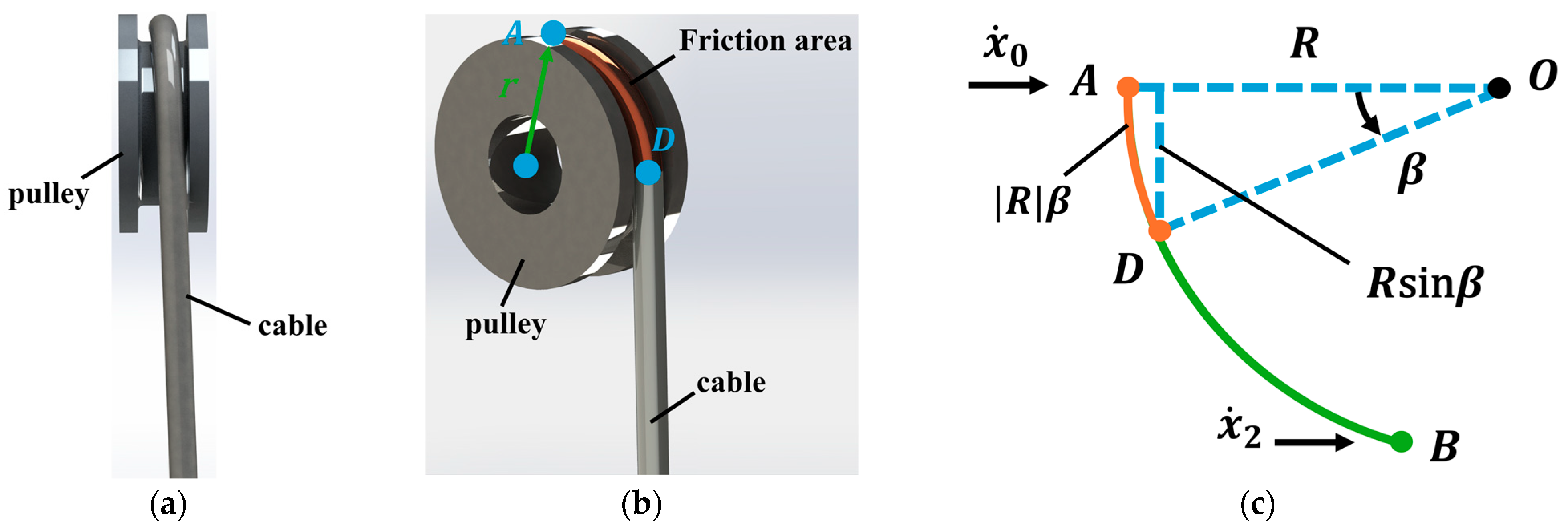
As shown in Figure 4, let r be the radius of the pulley at the endpoint of the cable. Then, the length of the contact line between the cable and the pulley is π 2 r . Let β denote the arc angle of the contact line between the cable and the pulley in the whole curved cable. Let R denote the bending radius of the cable. For the entire swinging cable, the relationship satisfied by this length is as follows:
π 2 r = R sin β = L θ sin β
Therefore, we can derive the following:
β = arcsin π r θ 2 L
The arc length of the friction between the cable and the pulley is R β . Let the normal support force per unit arc length be uniformly distributed:
d N = Δ m 1   L + m 2 g R β d s
f 1 represents the frictional force between the cable and the pulley contact area. Let the frictional element be as follows:
d f 1 = μ d N
where μ is the friction coefficient between the cable and the pulley.
Its differential moment about point A is as follows:
d M = L A D d f 1 = μ Δ m 1   L + m 2 g R β L A D d s
where L A D denotes the distance along the arc from point D to point A.
L A D θ = 2 R sin θ 2
Thus, the total frictional moment is as follows:
M f 1 = μ Δ m 1   L + m 2 g R β 0 R β L A D d s = 2 μ Δ m 1   L + m 2 g θ L arcsin π r θ 2 L 1 cos θ arcsin π r θ 2 L 2 L
The friction between air resistance and cable angular velocity is simplified as follows:
f 2 = k θ ˙
where k is a constant.
Accordingly, the total dynamic equilibrium equation governing the motion of the flexible cable system is given by the following [39,40,41,42]:
A * θ L + m 2 x ¨ 2 y 2 + m 2 g + y ¨ 2 L θ 1 cos θ + Δ m 1   L x ¨ 1 y 1 + Δ m 1   L g + y ¨ 1 L θ 2 θ sin θ + I θ θ ¨ + M f 1 + k θ ˙ = 0
Substituting Equations (7), (10), (11), (16), (19)–(22), (31), and (32) into Equation (33), the overall motion equilibrium equation of the cable can be expressed as follows:
π E 4 2 n 2 sin arctan P 2 2 π R 1 + R 2 2 + ν cos 2 arctan P 2 2 π R 1 + R 2 R 2 4 + R 1 4 + π E 4 2 n 4 sin arctan P 4 2 π R 3 + R 4 2 + ν cos 2 arctan P 4 2 π R 3 + R 4 R 4 4 + R 3 4 θ L + m 2 x ¨ 0 + L θ 3 θ 2 cos θ + 2 θ sin θ + 2 cos θ 2 θ ˙ 2 + θ θ sin θ cos θ + 1 θ ¨ L θ sin θ + m 2 g + L θ 3 θ 2 sin θ + 2 θ cos θ 2 sin θ θ ˙ 2 + θ sin θ θ cos θ θ ¨ L θ 1 cos θ + Δ m 1   L x ¨ 0 + L θ 2 sin θ 4 θ cos θ 2 θ + 6 sin θ θ 4 θ ˙ 2 + L θ cos θ + θ 2 sin θ θ 3 θ ¨ L θ 2 1 cos θ + Δ m 1   L g + L θ 2 cos θ 4 θ sin θ 6 cos θ + 6 θ 4 θ ˙ 2 + L θ sin θ + 2 cos θ 2 θ 3 θ ¨ L θ 2 θ sin θ + Δ m 1   L 3 θ 4 θ 2 2 θ s i n θ 2 cos θ + 2 + 2 m 2 L 2 θ 2 1 cos θ θ ¨ + 2 μ Δ m 1   L + m 2 g θ L arcsin π r θ 2 L 1 cos θ arcsin π r θ 2 L 2 L + k θ ˙ = 0
Let γ represent the angle between the line, which connects the upper and lower endpoints of the flexible cable, and the positive y-axis. Based on the system’s geometric constraints, the analytical relationship between γ and θ is derived as γ = θ 2 .

3. Numerical Discretization and Dynamic Optimization for Cable Motion Control Systems

Based on the cable dynamic model established in the previous section, this section proposes an optimal control strategy for the flexible cable system.
To solve this multi-constraint optimization problem, the present study achieves the optimal control of the upper endpoint velocity x ˙ 0 of the cable by optimizing the control period and deflection angle. A numerical discretization method is employed to transform the continuous-time dynamic system into a discrete form, thereby converting the originally complex continuous optimization problem into a computationally more tractable discrete optimization problem. On this basis, a numerical algorithm based on the RAER strategy is proposed, and the discretized solution process of the dynamic equations is elaborated in detail. By constructing a complete numerical solution framework, the proposed method can effectively solve complex cable dynamic optimization problems under multiple constraints.

3.1. Discretization Scheme and Trajectory Planning

The core objective of the optimization problem is to minimize the total transportation time t f required for the upper end of the cable to reach the target displacement, subject to multiple physical constraints. The specific constraints include the maximum velocity constraint k v , the maximum acceleration constraint k a , the maximum swing angle constraint k γ , the residual swing angle γ r e s , the target displacement k x , the cable length L , and the principle of acceleration continuity. Accordingly, the optimal trajectory is defined as the control strategy that minimizes the transportation time while satisfying all of the above constraints.
Figure 5 shows the flow diagram of the RAER trajectory planning strategy. The value of γ is indirectly determined by optimizing the control period T 1 and the deflection angle θ of the lower endpoint of the flexible cable, so as to achieve control in the shortest time ( k t ) used by the upper endpoint of the cable to complete target displacement ( k x ) under the constraints of the set maximum speed ( k x ˙ ), the maximum acceleration ( k x ¨ ), the maximum swing angle ( k γ ), and the residual swing angle ( γ r e s ). The core process is to use a numerical discretization model to transform the continuous dynamic problem into a discrete form that is easy to calculate by constructing a γ     t model, and then to solve the complex cable dynamics model to calculate the corresponding speed, acceleration, and displacement curves. The above explains the basic idea of reverse angle enumeration reasoning (RAER) in this study.
To facilitate the numerical solution of the dynamic equations, the total time interval 0 , 4 T 1 is discretized, where the discretization step is Δ t , and the corresponding discrete time nodes are as follows:
Δ t = 4 T 1 N
t i = i Δ t , i = 0 , 1 , , N
In a given range, discrete angle values and motion period values are generated from a search grid to find the optimal solution b e s t T 1 , b e s t r e s u l t . θ :
T 1 t r y T 1 s e a r c h
θ t r y θ r a n g e
where θ r a n g e = θ l o w , θ u p , and there are N 1 sampling points. T 1 s e a r c h =   T 1 m i n , T 1 m a x , with N 2 sampling points. In the search grid formed by θ t r y and T 1 t r y , the angle trajectory is constructed using the quintic polynomial in sequence, where θ max = θ t r y and T 1 = T 1 t r y .
Since this section is a theoretical derivation and concerns only a single complete oscillation period of θ , the quintic polynomial expression of the constructed θ changing with the current time t i is defined as follows:
τ i = t i T 1
θ t i = a 0 + a 1 τ i + a 2 τ i 2 + a 3 τ i 3 + a 4 τ i 4 + a 5 τ i 5 θ ˙ t i = a 1 + 2 a 2 τ i + 3 a 3 τ i 2 + 4 a 4 τ i 3 + 5 a 5 τ i 4 θ ¨ t i = 2 a 2 + 6 a 3 τ i + 12 a 4 τ i 2 + 20 a 5 τ i 3
Based on the boundary constraints, in order to ensure the smoothness of the periodic angle trajectory, the following constraints must be met when the angle θ increases from 0 to θ max :
θ t 0 = 0 ;   θ ˙ t 0 = 0 ;   θ ¨ t 0 = 0
θ t N 4 = θ max ;   θ ˙ t N 4 = 0 ;   θ ¨ t N 4 = 0
By imposing conditions (41) and (42) on the linear system (40), the values in (43) are obtained:
a 0 a 1 a 2 a 3 a 4 a 5 = θ max 0 0 0 10 15 6
The polynomial about the current time t i when the angle θ increases from 0 to θ max is derived as follows:
θ t i = θ max 10 τ i 3 15 τ i 4 + 6 τ i 5 ;   θ ˙ t i = θ max T 1 30 τ i 2 60 τ i 3 + 30 τ i 4 ;   θ ¨ t i = θ max T 1 2 60 τ i 180 τ i 2 + 120 τ i 3
Equation (44) can be rewritten as follows:
θ t i = θ max F 1 t i , T 1 ;   θ ˙ t i = θ max F 2 t i , T 1 ;   θ ¨ t i = θ max F 3 t i , T 1

3.2. Algorithmic Implementation for Dynamic Optimization

To solve the dynamic optimization problem, this paper proposes a numerical algorithm (Algorithm 1) based on an enumeration–verification strategy, with the detailed implementation presented in the form of pseudocode. The core idea of the algorithm is to discretize the search space in order to identify the global optimal solution.
Specifically, Algorithm 1 discretizes each combination of angle θ t r y and period T 1 t r y , and systematically enumerates all possible parameter pairs. For each candidate pair θ t r y , T 1 t r y , the algorithm first verifies whether the generated trajectory simultaneously satisfies both the dynamic system constraints and the geometric constraints. After identifying all feasible trajectories, the algorithm evaluates them using the task completion time t f as the performance index. Finally, the parameter combination that minimizes the task completion time is determined as the optimal solution of the system, and the corresponding optimal trajectory is stored as b e s t r e s u l t .
Although this enumeration–verification strategy entails relatively high computational complexity, it guarantees the identification of the global optimal solution within the discretization accuracy, thereby avoiding the issue of local optima.
Algorithm 1. The enumeration–verification method generates the current optimal solution of the system b e s t r e s u l t
Input:  θ l o w ,   θ u p ,   T 1 m i n ,   T 1 m a x ,   N ,   N 1 ,   N 2 ,   L ,   g ,   k ,   μ ,   r ,   k x ,   k x ˙ ,   k x ¨ ,   m 2 ,   Δ m 1 ,   E ,   ν ,   n 2 ,   n 4 ,
P 2 ,   P 4 ,   R 1 ,   R 2 ,   R 3 ,   R 4 .
Output:  b e s t T 1 ,   b e s t r e s u l t . θ ,   b e s t r e s u l t . x ,   b e s t r e s u l t . x ˙ ,   b e s t r e s u l t . x ¨ ,   b e s t r e s u l t . x .
1.
  b e s t T 1 = +
2.
  θ r a n g e = θ l o w + i N 1 1 θ u p θ l o w i = 0 , 1 , , N 1 1 π 180
3.
  T 1 s e a r c h = T 1 m i n + j N 2 1 T 1 m a x T 1 m i n j = 0 , 1 , , N 2 1
4.
  Select a trial value θ t r y from the interval θ r a n g e in sequence:
5.
f o r   θ t r y θ r a n g e
6.
   Select a trial value T 1 t r y from the interval T 1 s e a r c h sequence:
7.
   for  T 1 t r y     T 1 s e a r c h
8.
      try
9.
       Δ t = 4 T 1 t r y N
10.
        t v e c = 4 i N T 1 t r y i = 0 , 1 , , N
11.
    θ , θ ˙ , θ ¨ = θ _ p e r i o d i c _ w a v e f o r m t v e c ,   T 1 t r y ,   θ t r y
12.
    x , x ˙ ,   x ¨ = c o m p u t e _ x ˙ _ d y n a m i c s θ , θ ˙ , θ ¨ , L , g , k , μ , r , Δ t , k x , T 1 t r y , m 2 , Δ m 1 , E , ν , n 2 , n 4 , P 2 , P 4 , R 1 , R 2 , R 3 , R 4 )
13.
    i f   max x ˙ 0 k x ˙ & & max x ¨ 0 k x ¨
14.
     i f   T 1 t r y < b e s t T 1
15.
      b e s t T 1 = T 1 t r y , b e s t r e s u l t . θ = θ t r y , b e s t r e s u l t . t = 4 T 1 t r y , b e s t r e s u l t . x = x 0 e n d ,
b e s t r e s u l t . x ˙ = max x ˙ 0 , b e s t r e s u l t . x ¨ = max x ¨ 0
16.
       end
17.
      end
18.
   end
19.
  end
In Algorithm 1, θ l o w , θ u p , T 1 m i n , T 1 m a x represent the minimum and maximum values of θ and T 1 , respectively. These parameters are determined according to engineering practice, and the most important is θ u p = k θ = 2 k γ . N is the number of discrete steps of 4 T 1 t r y ; N 1 and N 2 are the number of elements in θ r a n g e and T 1 s e a r c h , respectively. t v e c , θ r a n g e , T 1 s e a r c h denote the number of elements in the discrete sets, corresponding to the discretization steps of time, angle, and period values. k t specifies the total operating time of the system, while k x , k x ˙ , k x ¨ constrain the peak values of displacement, velocity, and acceleration during system operation; these parameters are also determined based on engineering requirements. The variables b e s t T 1 , b e s t r e s u l t . θ , b e s t r e s u l t . x , b e s t r e s u l t . x ˙ , b e s t r e s u l t . x ¨ , and b e s t r e s u l t . t store the optimal solution of the system, including the corresponding period value, angle value, actual arrival time, actual displacement, maximum velocity, and maximum acceleration. Finally, x 0 e n d denotes the ultimate value obtained after the numerical integration of k x .
The specific numerical implementation of the function θ _ p e r i o d i c _ w a v e f o r m involved in Algorithm 1 in this study is Algorithm A1. Specifically, for any given discrete angle θ t i , Algorithm A1 processes the candidate solutions θ t r y , T 1 t r y in sequence, generates the angle trajectory corresponding to the current time t i , and thus obtains the discretized angle sequence θ t i . The pseudocode implementation of Algorithm A1 is provided in Appendix A.2.
Based on the discretized ( θ k ) trajectory obtained from any discrete angle ( θ t i ), upper endpoint acceleration x ¨ 0 t i is inferred through the kinematic relationship and the dynamic equation.
Rewriting Equations (6)–(11) and (15)–(20) in a discretized form yields the discretized calculation formulas for the displacement, velocity, and acceleration of the centroid and lower endpoint, θ i = θ t i , θ ˙ i = θ ˙ t i , and θ ¨ i = θ ¨ t i :
x 1 , i = x 0 , i L θ i 2 θ i sin θ i y 1 , i = L θ i 2 1 cos θ i x 2 , i = x 0 , i L θ i 1 cos θ i y 2 , i = L θ i sin θ i
x ˙ 1 , i = x ˙ 0 , i + L θ i cos θ i + θ i 2 sin θ i θ ˙ i θ i 3 y ˙ 1 , i = L θ i sin θ i + 2 cos θ i 2 θ ˙ i θ i 3 x ˙ 2 , i = x ˙ 0 , i L 1 cos θ i θ i 2 sin θ i θ i θ ˙ i y ˙ 2 , i = L sin θ i θ i 2 cos θ i θ i θ ˙ i
x ¨ 1 , i = x ¨ 0 , i + L θ i 2 sin θ i 4 θ i cos θ i 2 θ i + 6 sin θ i θ i 4 θ ˙ i 2 + L θ i cos θ i + θ i 2 sin θ i θ i 3 θ ¨ i y ¨ 1 , i = L θ i 2 cos θ i 4 θ i sin θ i 6 cos θ i + 6 θ i 4 θ ˙ i 2 + L θ i sin θ i + 2 cos θ i 2 θ i 3 θ ¨ i x ¨ 2 , i = x ¨ 0 , i L θ i 3 θ i 2 cos θ i + 2 θ i sin θ i + 2 cos θ i 2 θ ˙ i 2 + θ i θ i sin θ i cos θ i + 1 θ ¨ i y ¨ 2 , i = L θ i 3 θ i 2 sin θ i + 2 θ i cos θ i 2 sin θ i θ ˙ i 2 + θ i sin θ i θ i cos θ i θ ¨ i
where x 0 , i   =   x 0 t i is the displacement of the upper endpoint at t i .
Discretizing Equation (34) allows for the calculation of upper endpoint acceleration.
Although Equation (34) appears computationally complex, it is essentially solved under the condition that parameter θ i is known, with only one unknown variable, parameter x ¨ 0 .
We can numerically integrate velocity and displacement as follows:
x ˙ 0 t i + Δ t = x ˙ 0 t i + x ¨ 0 t i Δ t ;   x 0 t i + Δ t = x 0 t i + x ˙ 0 t i Δ t
We repeat the iteration for all t i     0 , 4 T 1 , and finally obtain the angle trajectory θ t i , velocity trajectory x ˙ 0 t i , acceleration trajectory x ¨ 0 t i , and displacement x 0 t i sequence at the discrete angle θ i .
Based on the above kinetic modeling, we can verify whether the following constraints are met:
max θ k θ ;   max x ˙ 0 k x ˙ ;   max x ¨ 0 k x ¨
The specific implementation of the function c o m p u t e _ x ˙ _ d y n a m i c s involved in Algorithm 1 of this study is Algorithm A2. For all discrete angles θ t i , acceleration of the upper endpoint x ¨ 0 t i can be inferred through the kinematic relationship and the dynamic equation. Based on this, the constraint conditions are verified. The pseudocode implementation of Algorithm A2 is provided in Appendix A.2.
In Algorithm A2, parameter i = 0 N   x 0 t i   =   k x denotes the numerical integration of displacement, which is used to calculate the cumulative displacement of the system during the entire motion process. Parameter k x represents the target displacement value, which needs to be predefined according to task requirements. In algorithm implementation, the total displacement is approximated by numerically integrating parameter x 0 t corresponding to the discrete time sequence t v e c and then compared with the target parameter k x to determine whether the trajectory satisfies the displacement constraint.

4. Simulation Verification and Analysis

4.1. Flexible Cable Kinematics Simulation

In order to verify the validity and accuracy of the proposed flexible cable dynamic model, a simulation system was built on the Matlab/Simulink platform. The simulation is based on a typical single-cable crane structure, and the relevant system parameters are set as follows:
E = 2.0685 × 10⁸ kPa; ν = 0.29; P2 = 3.31 × 10⁻³ m; P4 = 5.44 × 10⁻³ m; R1 = 9.82 × 10⁻⁵ m; R2 = 9.21 × 10⁻⁵ m; R3 = 8.64 × 10⁻⁵ m; R4 = 8.2 × 10⁻⁵ m; n2 = 6; n4 = 6; m2 = 3 kg; L = 0.45 m; g = 9.81 m/s2.
For θ 0 , considering that this parameter will cause a singularity in the equation when it is theoretically zero, affecting numerical stability, it is replaced by a very small positive number to ensure the well-conditioned nature of the calculation process. The final displacement of the upper endpoint of the cable is k x = 1 m. The mass per unit length of the cable is Δ m 1   =   0.01 kg/m. We assume that k = 0 and μ = 0 in the absence of damping.
Meanwhile, in conjunction with Figure 6, the kinematic equation of the rigid cable model is given by the following [39,40,41,42]:
m 2 L cos θ x ¨ 0 + m 2 L 2 θ ¨ + m 2 g L sin θ = 0
Formula (51) is used to generate angle prediction results under the traditional rigidity assumption.
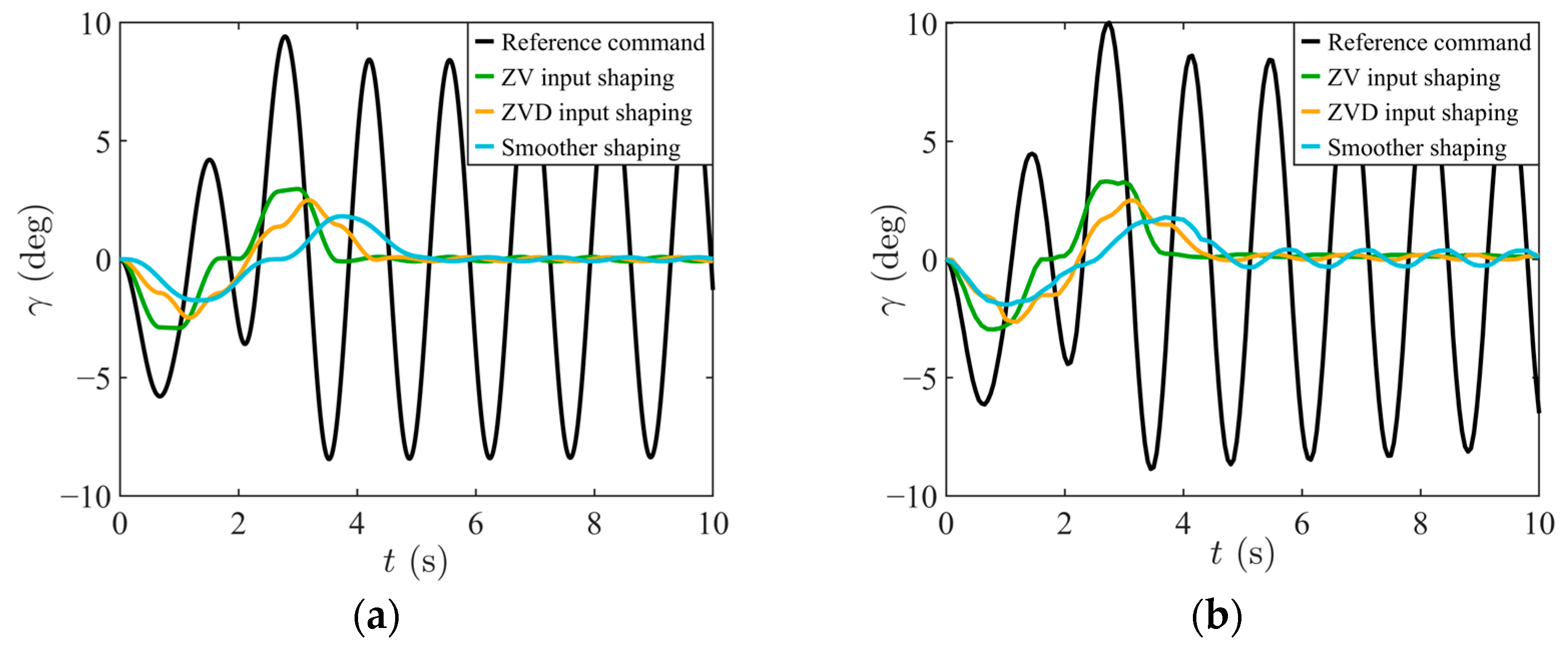
In addition, in order to comprehensively evaluate the prediction accuracy of the flexible cable kinematic model in this study based on the angle at different speeds, three existing control methods (ZV input shaping [43], ZVD input shaping [10,11], smoother shaping [12]) and a reference command without control are selected as the input speed of the upper endpoint on the cable. To ensure fair comparison, the parameters of the control strategy used for comparison are as follows: k x ˙ = 0.5 m/s, k x ¨ = 0.5 m/s2, k x = 1 m, and L = 0.45 m; the total motion time is 10 s. The simulation results of angle prediction under different speed conditions are compared to verify the effectiveness and robustness of the model built in this study at any speed.
Figure 7 shows the speed curves under different control methods (ZV input shaping, ZVD input shaping, smoother shaping) and the reference command. All control strategies are generated under the same motion constraints: the maximum speed limit is k x ˙ = 0.5 m/s, the maximum acceleration limit is k x ¨ = 0.5 m/s2, the total motion time is 10 s, the target displacement is k x = 1 m, and the cable length is L = 0.45 m. This figure intuitively reflects the speed curves under different control strategies, providing a conditional basis for the comparative analysis of subsequent angle prediction.
.
Figure 8a presents the simulation results of the flexible cable swing angle γ under different control speeds, while Figure 8b shows the corresponding experimental results. By comparing the magnitudes and variation trends in the two figures, it can be observed that the simulated and experimental values of γ exhibit a high degree of consistency across different control speeds. This outcome not only verifies the correctness of the flexible cable motion equations and deformation modeling, but also demonstrates that the proposed model possesses strong generality and reliability in swing angle prediction.
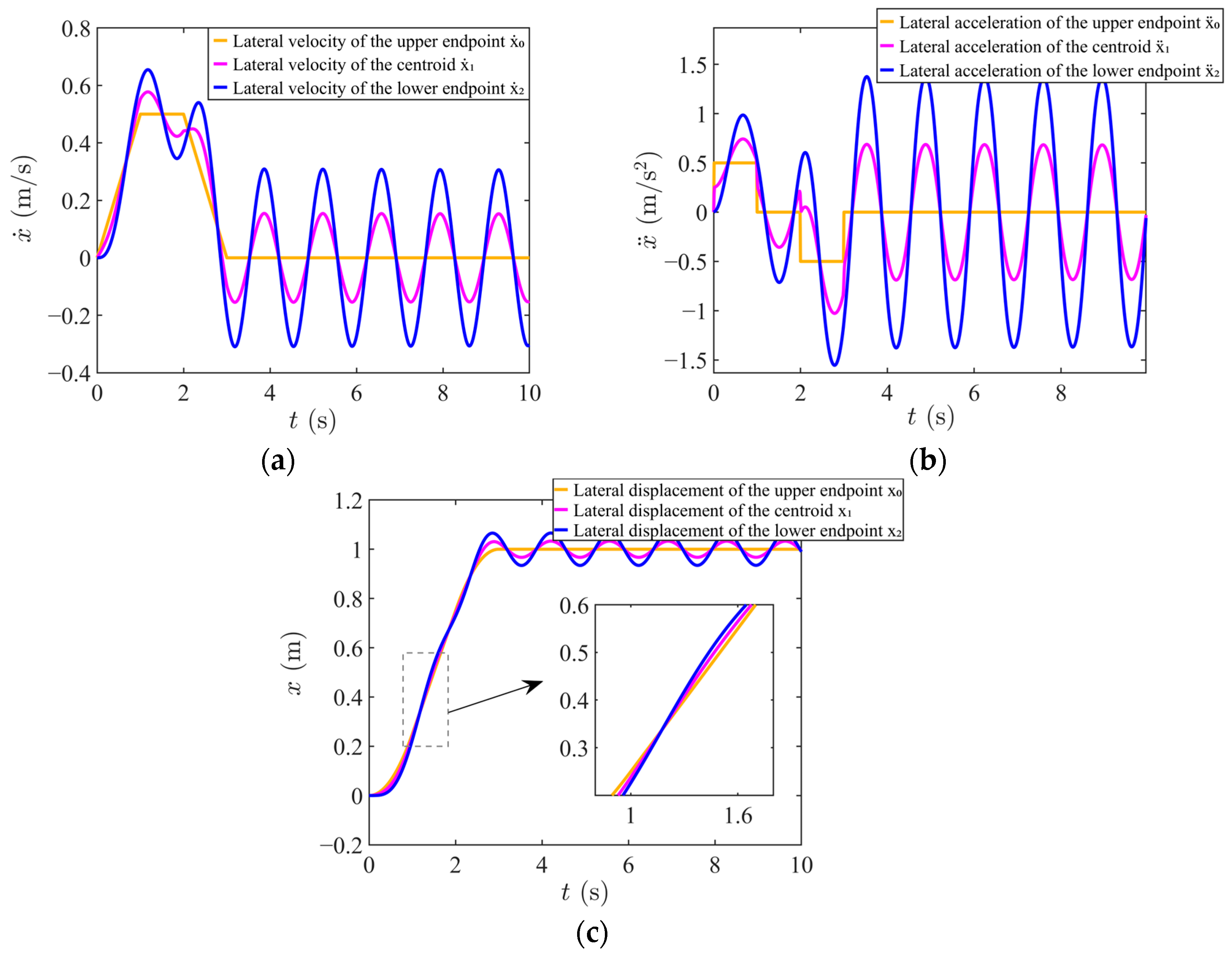
Figure 9a represents the horizontal velocity plots of the upper endpoint, centroid, and lower endpoint of the cable at the speed of the reference command. Figure 9b shows the horizontal acceleration of the upper endpoint, centroid, and lower endpoint of the cable at the speed of the reference command. Figure 9c represents the horizontal displacement of the upper endpoint, centroid, and lower endpoint of the cable under the reference command.
Based on the prediction of the angle change of the cable, we perform horizontal displacement analysis on three important points (upper endpoint, centroid, and lower endpoint) to verify the validity of the proposed flexible cable model, as shown in Figure 9. The simulation results show that the horizontal displacement of the upper endpoint meets the displacement constraint of 1 m, proving the accuracy of the deformation simulation carried out by the model. At the same time, the displacement response of different position points reflects the real swing and bending deformation characteristics of the cable during movement. In addition, the velocity and acceleration curves shown in Figure 9a,b further reveal the dynamic response characteristics of the system during the swing process, indicating that the model has good rationality and stability in describing the dynamic behavior of a flexible cable.
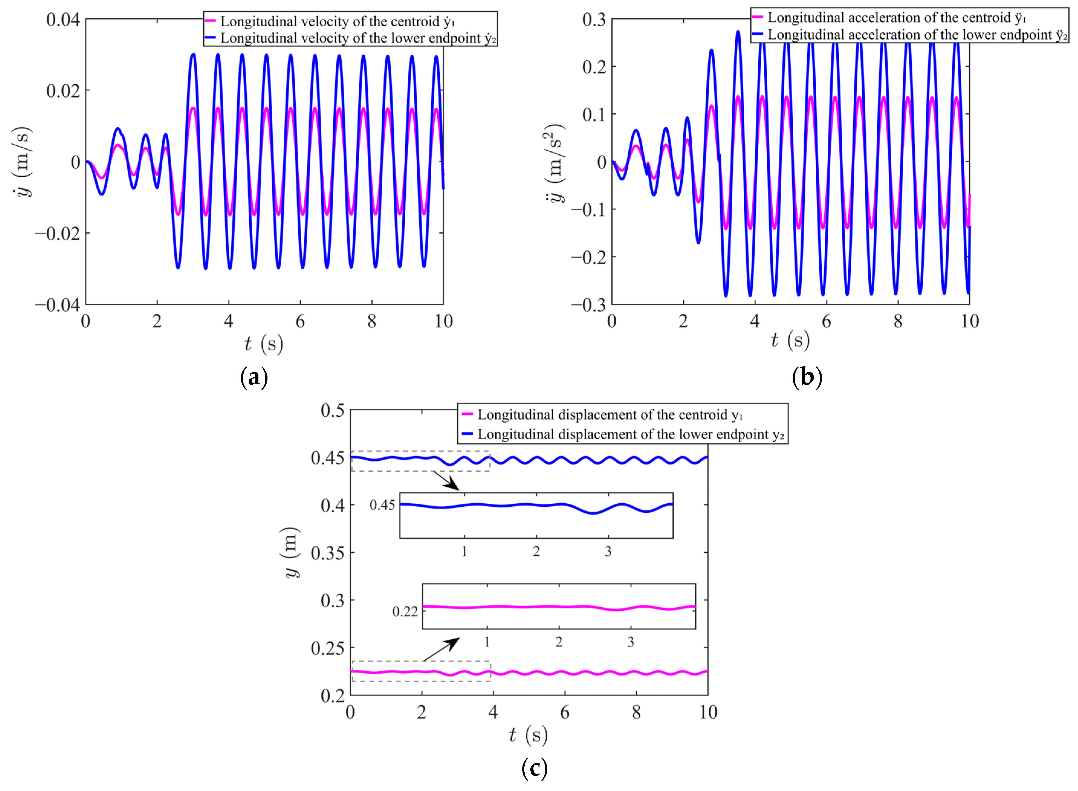
Figure 10a shows the vertical velocity of the centroid and the lower endpoint of the cable under the reference command. Figure 10b shows the vertical acceleration of the centroid and the lower endpoint of the cable under the reference command. Figure 10c represents the vertical displacement of the centroid and the lower endpoint of the cable under the reference command.
To further verify the accuracy of the vertical displacement of the cable model during bending deformation, Figure 10 analyzes the displacement, velocity, and acceleration response of the centroid and the lower endpoint in the vertical direction. The simulation results show that the maximum vertical displacement of the centroid is about 0.23 m, and the maximum vertical displacement of the lower endpoint is about 0.45 m, which is consistent with the geometric characteristics of the cable. The dynamic behavior in the vertical direction can effectively reflect the local bending characteristics of the cable during movement, further verifying the physical consistency and modeling reliability of the proposed flexible cable model in describing complex deformation behavior.
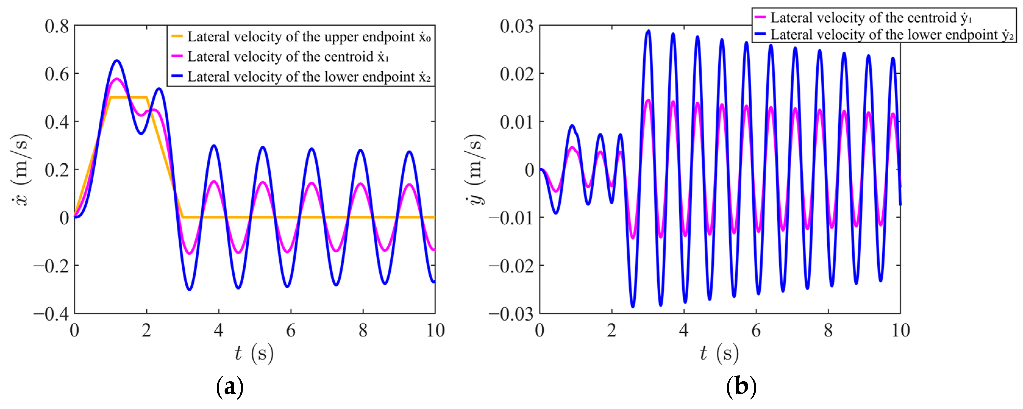
In order to more realistically reflect the dynamic characteristics of the flexible cable under actual working conditions, this paper introduces a damping term based on the original model, and its parameters are set to k   =   0.001   kg m 2 / s and μ   =   0.02 . Figure 11a represents the horizontal velocity plots of the upper endpoint, centroid, and lower endpoint of the cable at the speed of the reference command after adding damping. Figure 11b represents the vertical velocity plots of the centroid and lower endpoint of the cable at the speed of the reference command after adding damping.
Taking the lower endpoint as an example, after adding damping, its maximum speed in the horizontal direction is slightly reduced from 0.30 m/s to 0.27 m/s, and the maximum speed in the vertical direction is reduced from 0.03 m/s to 0.02 m/s. Compared with the case without damping, the dynamic response of the system after introducing damping is closer to the actual situation, and the continuity and stability of the velocity curve are improved. Therefore, the introduced damping term is reasonable in physical modeling. The addition of damping not only improves the accuracy and authenticity of the model, but also provides a more realistic dynamic basis for the design and optimization of subsequent control strategies.

4.2. Validation of Speed Optimization Simulation and Comparative Analysis of Performance

In order to verify the superiority of the proposed speed optimization algorithm, some simulation tests in Matlab/Simulink are conducted. The tests are based on the numerical discretization method. Algorithm 1 converts the continuous dynamic problem into a discrete form, which is convenient for calculation.
The total time interval 0 10 s is discretized with a step size of Δ t = 0.05 s to obtain discrete time nodes t i = i Δ t , where i = 0 , , 200 . This generates discrete angle values and motion period values within a given range to form a search grid for finding the optimal solution, denoted as b e s t T 1 , b e s t r e s u l t . θ . Specifically, the angle value θ t r y is sampled from the range θ r a n g e = 2 3 deg, with N 1   =   30 sampling points, and the motion cycle value T 1 t r y is sampled from the range T 1 s e a r c h = 0.2 5 deg, with N 2   =   60 sampling points.
Based on the search grid composed of θ t r y and T 1 t r y , Algorithm A1 is used to construct discrete angle trajectories. During the construction process, the time parameter is standardized according to the following formula:
τ i = t i T 1 ,   t i T 1 t i T 1 T 1 ,   T 1 < t i 2 T 1 t i 2 T 1 T 1 ,   2 T 1 < t i 3 T 1 t i 3 T 1 T 1 ,   3 T 1 < t i 4 T 1
where t i 0 , 4 T 1 .
Based on the discrete angle trajectory generated by Algorithm A1, Algorithm A2 is used to calculate the acceleration of the upper endpoint. The acceleration is inferred through the motion relationship and dynamic equations, and the corresponding velocity and displacement are obtained using the numerical integration method. The optimal solution is obtained by verifying the constraints.
The system’s parameter settings for the simulation test in this section are consistent with the parameter settings for the verification of the flexible cable dynamic equation in Section 4.1. The final displacement of the upper endpoint of the cable is set to k x = 1 m, the cable length is set to L = 0.45 m, the mass of the weight at the end of the cable is set to m 2 = 3 kg, and the total motion time of the simulation system is t 4 = 10 s. The constraints imposed by the system are as follows: velocity constraint k x ˙ = 0.5 m/s and acceleration constraint k x ¨ = 0.5 m/s2. In addition, one angle constraint is set, namely k γ = 1.5 deg. The input parameters of damping are set as follows: k   =   0.001   kg m 2 / s , μ   =   0.02 , r = 0.01 m, and ε = 10 6 .
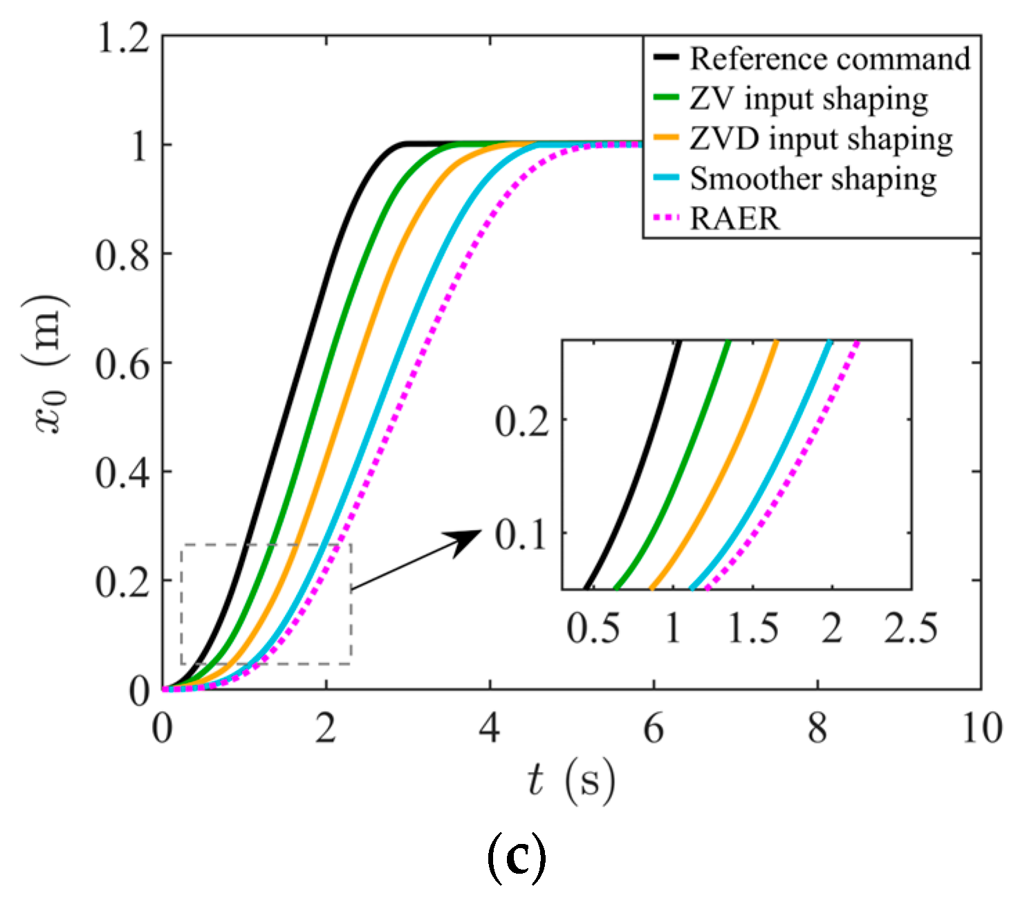
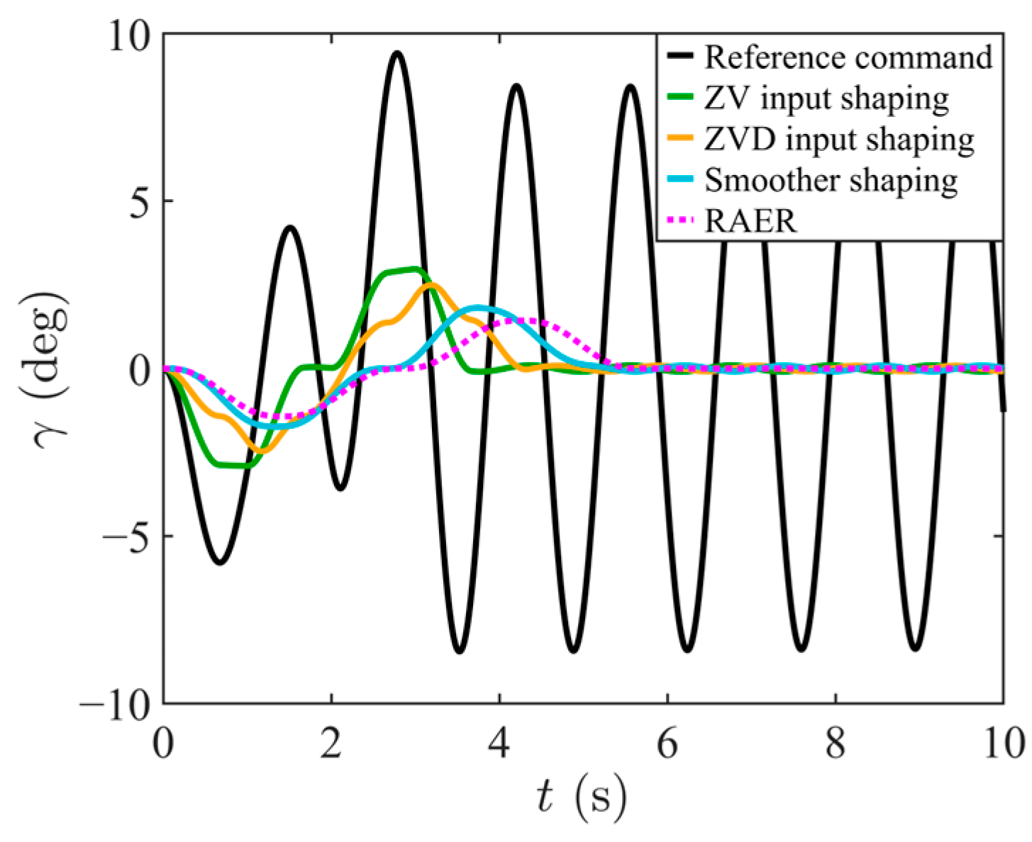
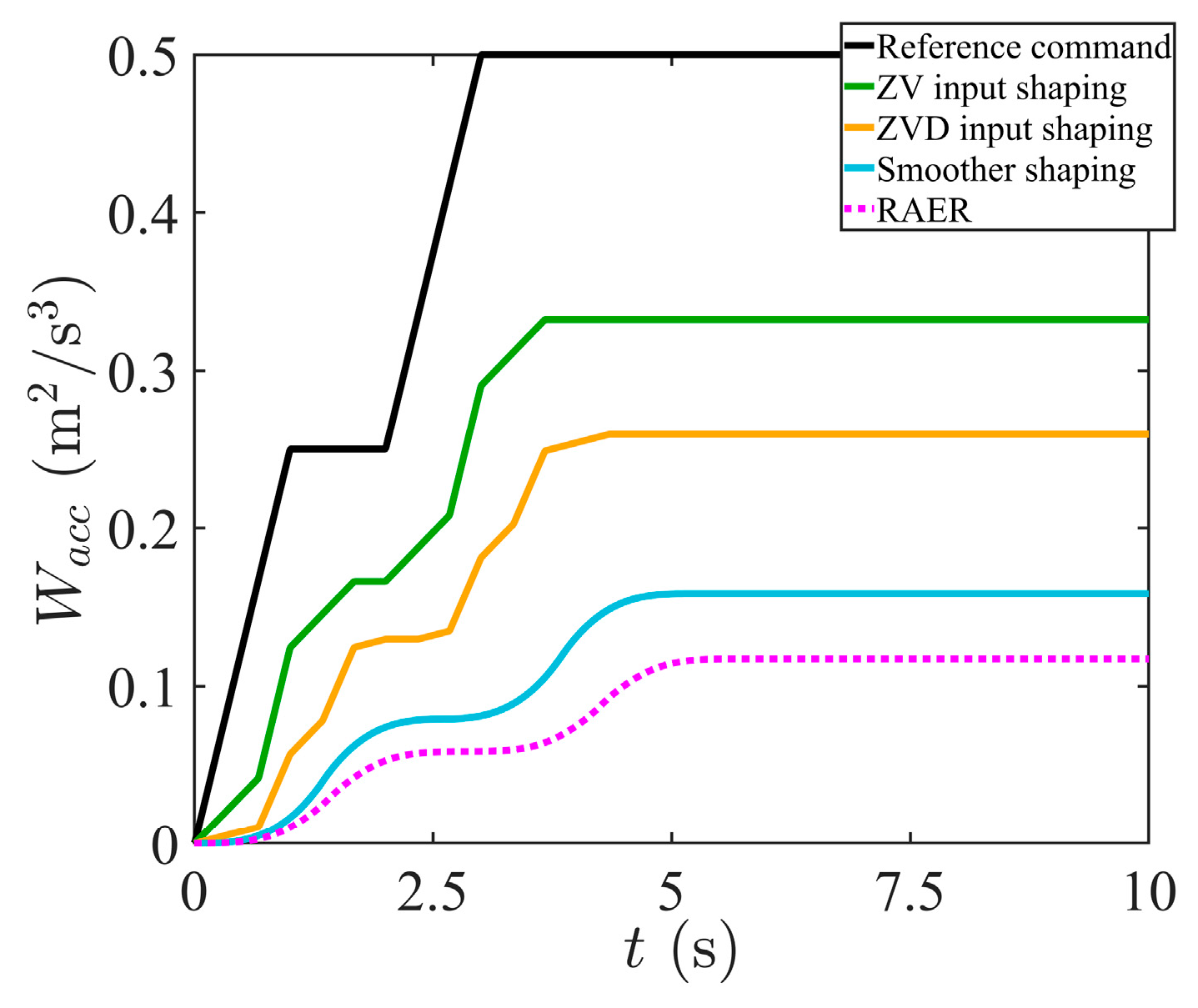
Figure 12a–c shows, respectively, the curves of the velocity, acceleration, and displacement of the upper endpoint of the cable obtained through simulation according to the above parameter settings. Figure 13 shows the curve of the γ of the flexible cable obtained through simulation and changing with time. Figure 14 shows the simulation results for energy cost.
The following five indicators are used to judge the control performance between different strategies:
(1)
γ m a x is the maximum angle between the line connecting the upper and lower endpoints of the flexible cable and the vertical direction in the optimal result, where γ m a x = max t t i γ t ;
(2)
t f is the time taken to reach the target distance k x in the optimal result;
(3)
γ r e s is the residual swing angle between the line connecting the upper and lower endpoints of the flexible cable and the vertical direction when reaching the target distance k x in the optimal result, where γ r e s = max t > t f γ t ;
(4)
x ˙ 0 , max is the maximum velocity of the upper endpoint of the flexible cable in the optimal result, where x ˙ 0 , m a x = max t t i x ˙ 0 t ;
(5)
x ¨ 0 , m a x is the maximum acceleration of the upper endpoint of the flexible cable in the optimal result, where x ¨ 0 , m a x =   max t t i x ¨ 0 t ;
(6)
W a c c is defined as a variable representing the energy cost for the movement of the trolley, and the motor’s energy consumption is proportional to its acceleration, where W a c c = 0 t f x ¨ 0 2 d t [42,44,45].
When the constraint k γ is taken as 1.5 deg, the optimal control results obtained by using the optimization strategy (RAER) of this system show significant improvement.
Specifically, when the constraint condition k γ = 1.5 deg, the maximum angle γ m a x between the line connecting the upper and lower endpoints of the flexible cable and the vertical direction in the optimal result is 1.43 deg, the residual swing angle of the flexible cable γ r e s is 0 deg when reaching the target distance k x , the corresponding actual running time t f is 5.58 s, and the maximum velocity and maximum acceleration are 0.35 m/s and 0.25 m/s2, respectively. The performance indicators of the simulation are summarized in Table 1.
Figure 13 presents the simulation curve of the maximum angle γ m a x of the flexible cable under various control strategies. Similarly, Table 1 provides an analysis of the residual swing angle γ m a x of the flexible cable when reaching the target distance under these strategies. The simulation results indicate that the γ m a x values under the reference command, ZV input shaping, ZVD input shaping, and smoother shaping control strategies are 9.42, 2.97, 2.49, and 1.81 deg and the corresponding γ m a x values are 8.45, 0.10, 0.03, and 0.08 deg, respectively. In contrast, after optimization of RAER, this system achieves a maximum swing angle of 1.43 deg and a residual swing angle of 0 deg, demonstrating that the RAER strategy effectively confines the swing within a narrower range.
This optimization significantly enhances the stability and safety of system ope-ration, ensuring a reduced swing amplitude after movement cessation and improving the overall accuracy.
Figure 12c presents the simulation curve of x 0     t taken by the upper endpoint of the flexible cable reaching the target distance under different control strategies, while Figure 12a,b show the simulation curves of velocity and acceleration, respectively. Simulation analysis reveals that t f under the control of the reference command, ZV input shaping, ZVD input shaping, and smoother shaping is 2.93, 3.59, 4.26, and 4.60 s, respectively. When optimized by using the RAER method, t f is extended to make the curve change more gently, effectively avoiding the instantaneous impact caused by violent fluctuations. Upon comparison of the velocity and acceleration curves, it can be observed that the control strategies based on the reference command and ZV input shaping generally meet the constraint requirements. However, ZVD input shaping and smoother shaping, while slightly improving the experimental data, still exhibit large fluctuations. In contrast, the RAER control strategy significantly reduces the oscillation amplitude, with velocity and acceleration oscillation amplitudes decreasing to 0.35 m/s and 0.25 m/s2.
Figure 14 and Table 1 indicate the simulation results for energy cost W a c c t . It can be seen that the minimum energy cost for the system is 0.12 m2/s3 under the control of RAER, which further demonstrates the rationality of the RAER method.
This strategy not only improves the smoothness and stability of the curves, but also minimizes the distortion in speed curve execution. Compared to the preoptimization case, the optimized speed curve facilitates more accurate tracking and execution. These results validate the effectiveness of the RAER strategy in enhancing the dynamic performance of the system. The simulation results are in strong agreement with the theoretical analysis, confirming that the optimization strategy improves the system’s dynamic response characteristics.

4.3. Experiments and Analysis

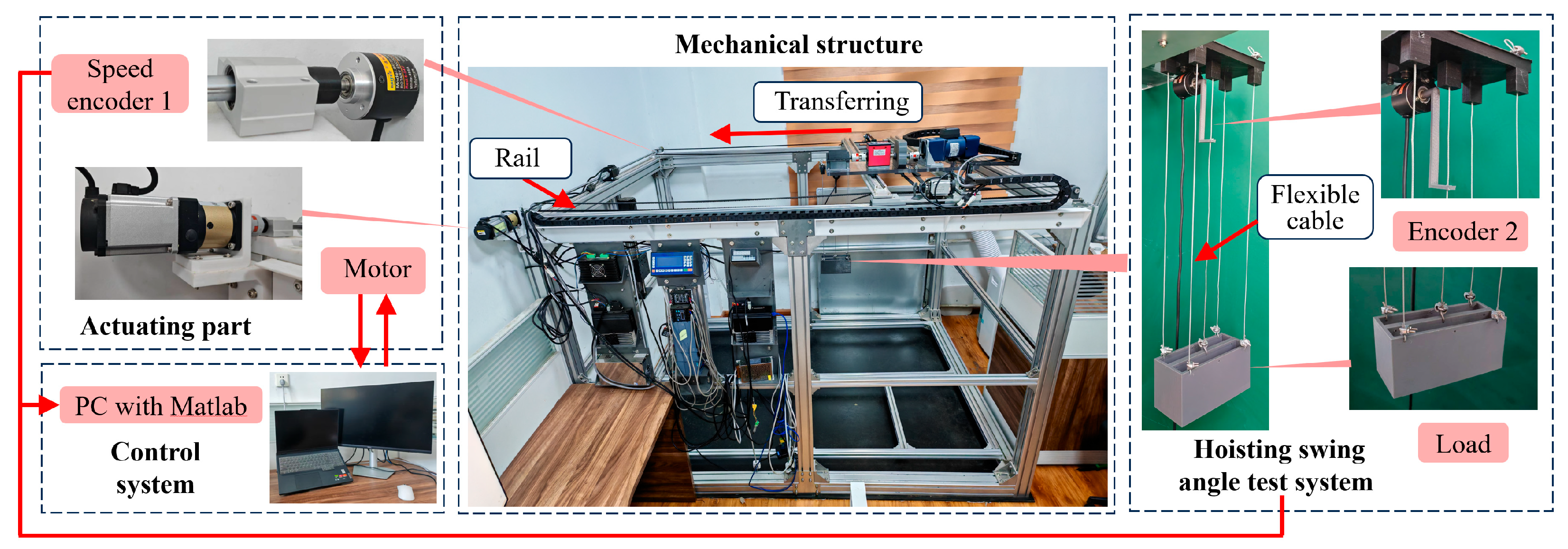
In this section, the proposed RAER velocity trajectory optimization algorithm is validated using a self-built crane platform, as shown in Figure 15. For safety reasons, the experimental platform employs multiple cables to suspend a rigid payload, while the main dynamic response is governed by a single flexible cable. The auxiliary cables are mainly used to enhance stability, and their influence on the swing dynamics of the payload can be neglected. Therefore, the experimental results can be reasonably compared with the single-cable model. In the experimental setup, the payload is connected to the lifting platform via a steel cable, while the belts and sliding rails mounted on both sides of the platform provide the driving force and guide its motion along the predefined track. The system is powered by a 0.4 kW AC servo motor, whose encoder continuously monitors motor status and assists the computer in precisely controlling motion trajectory. The real-time operating speed of the platform is measured by Encoder 1 (17-bit), which is coaxially mounted with the servo motor, while the payload swing angle is measured by Encoder 2 (17-bit) installed on the lifting platform. The servo driver communicates with the computer via a serial port and receives high-speed instruction sets through the Modbus RTU485 protocol.
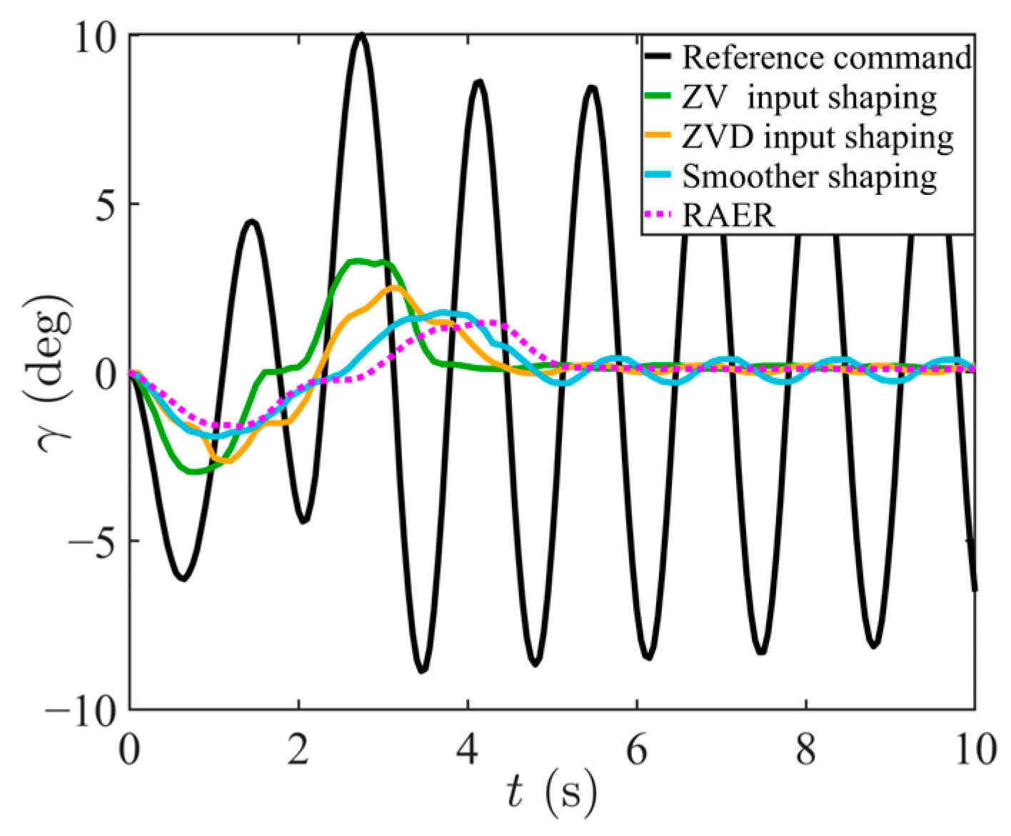
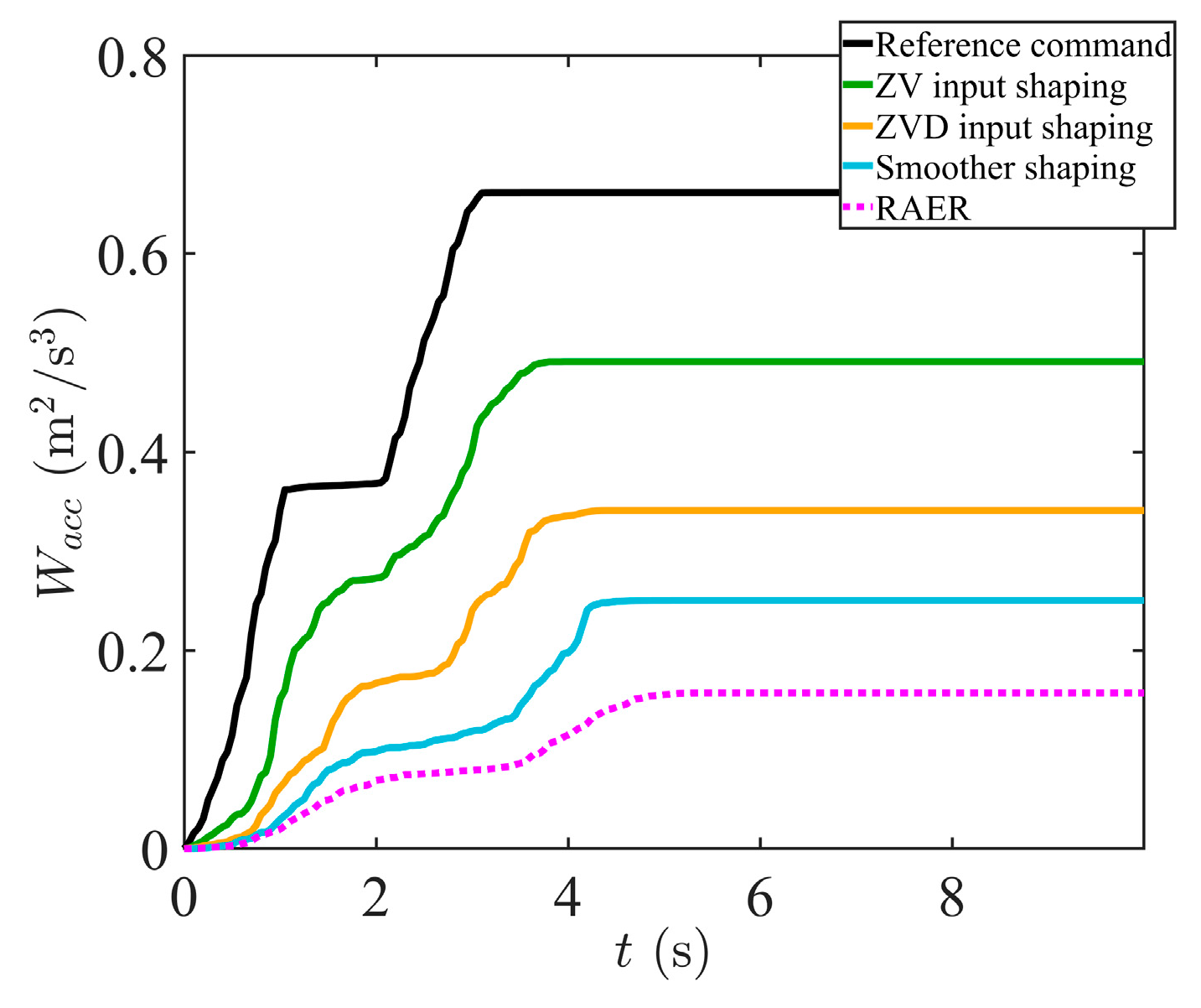
The system’s parameters, the state constraints, the input parameters of the proposed method, and the parameters of the comparison methods are the same as those used in the simulation. The experimental results comparing the existing methods and the proposed RAER algorithm are shown in Figure 16 and Figure 17. Figure 18 shows the experiment results for energy cost.
Figure 16a presents the experimental acceleration results for transporting heavy objects under various control strategies, including the existing control methods compared and the proposed RAER algorithm. Due to the absence of an accelerometer on the self-assembled bridge crane platform, acceleration data were obtained by numerically differentiating the velocity signal, while the displacement results were derived by numerically integrating velocity over time. From the experimental data, it can be seen that numerical differentiation inevitably introduces noise, causing slight deviations between the experimental and simulation results. Despite noise interference, the reference command, ZV input shaping method, and ZVD input shaping methods exhibit maximum accelerations of 1.10 m/s2, 0.89 m/s2, and 0.71 m/s2, respectively, all showing clear constraint violations. The smoother shaping strategy achieves a maximum acceleration of 0.68 m/s2, but still violates constraints in some cases. In contrast, the proposed RAER algorithm effectively suppresses noise interference, maintaining acceleration within the specified range, with a maximum acceleration of only 0.39 m/s2. The RAER algorithm significantly reduces the oscillation amplitude.
Figure 16b shows the experimental speed curve obtained from the self-built overhead crane platform, where the servo motor operates in speed control mode and can directly accept speed commands. The speed trajectory closely matches the corresponding simulation results, confirming the motor’s accuracy in following input commands. Experimental analysis indicates that the maximum transmission speeds achieved by the reference command, ZV input shaping, ZVD input shaping, and smoother shaping methods are 0.51, 0.50, 0.47, and 0.41 m/s, respectively. In contrast, the proposed RAER strategy achieves a maximum operating speed of 0.36 m/s. The lower theoretical motor speed peak makes the actual speed less prone to distortion in practice. Furthermore, while reducing peak speed, the RAER algorithm generates a significantly smoother speed curve, contributing to better tracking performance and overall system stability. The experimental results demonstrate that the inherent optimization between the maximum speed and trajectory smoothness in the RAER method provides favorable performance characteristics for practical applications in crane control systems. The control performance data of the experiments are shown in Table 2.
Figure 16c and Figure 17, respectively, present the experimental results of transportation displacement and cable swing angle, comparing the performance of different control strategies. Table 2 summarizes the experimental results. At a 1 m moving distance, the maximum swing angles obtained with the reference command, ZV, ZVD, and smoother shaping are 10.00°, 3.30°, 2.64°, and 1.91°, respectively; the corresponding residual swing angles are 8.96°, 0.31°, 2.64°, and 1.91°. Under the proposed RAER algorithm, the maximum and residual swing angles are further reduced to 1.60° and 0.03°, respectively. The RAER algorithm also yields the smallest velocity and acceleration, at 0.36 m/s and 0.39 m/s2. Although this comes at the cost of a slightly longer motion duration, it substantially enhances battery pack safety. In terms of energy comparison, the RAER algorithm requires the least amount of energy, only 0.16 m2/s3, which is 36.00% less than that required for smoother shaping. Therefore, among the methods compared, RAER is the only one that simultaneously satisfies full-state constraints while minimizing energy consumption.

5. Discussion

In this experimental setup, the load is symmetrically suspended by five cables under a rigid hanger. Although the static load is shared by all cables, the system exhibits clear dynamic characteristics in small angle swings (swing angle < 1.5°) during normal planar operation: the central cable aligned with the trolley motion direction dominates the main planar swing response, bearing the dynamic forces caused by trolley acceleration and deceleration.
The remaining four auxiliary cables are slightly preloaded, mainly to suppress torsion and non-planar motion and provide redundancy. Due to the symmetrical layout and load rigidity, the dynamic tension change of the auxiliary cable during small amplitude swinging is much smaller than that of the central cable, and its impact on swing dynamics can be regarded as quasi-static. Therefore, it will not introduce significantly independent oscillation modes and change the dominant dynamics described by the single-cable model.
The experimental data strongly validate the accuracy of the simplified model: the simulation of the single-cable model is highly consistent with the measured swing response (Section 4 and Table 2), and the residual swing angle is as low as 0.03°, indicating that the unmodeled auxiliary cable power effect can be ignored.
Therefore, it is reasonable and necessary to adopt a single-cable model for modeling and control design of small-angle swing dynamics. This simplification not only preserves the essential physical characteristics of the system, but also considers the feasibility of analysis.

6. Conclusions

This study develops a nonlinear flexible cable dynamics model for bridge cranes and proposes a numerical discretization and dynamic optimization method for the cable motion control system. A discretization scheme and trajectory planning algorithm are introduced. Finally, kinematic and velocity optimization simulations are conducted and validated through experiments. The simulation and experimental results show that the flexible cable model can accurately predict the dynamic response of the cable, effectively capturing its trajectory and attitude changes. Moreover, the REAR scheme significantly enhances the motion characteristics of the bridge crane system.

Author Contributions

Conceptualization, G.Y. and Y.C.; methodology, G.Y.; software, J.W.; validation, Y.L. (Yifei Liu), J.W. and Z.C.; formal analysis, G.L.; investigation, L.W.; resources, Y.Z.; data curation, Y.L. (Yifei Liu); writing—original draft preparation, G.Y., Y.C. and Y.L. (Yutian Lei); writing—review and editing, L.W.; visualization, J.W.; supervision, G.L. and Y.Z.; project administration, Z.C. and C.L.; funding acquisition, Z.C., Y.Z. and C.L. All authors have read and agreed to the published version of the manuscript.

Funding

The study described in this paper was supported by the Taiyuan City’s Key Core Technology Research Project (No. 2024TYJB0135), the National Natural Science Foundation of China (No. 12402416), the Fundamental Research Program of Shanxi Province (No. 202203021222084, 202403021222058), and the Postdoctoral Fellowship Program of CPSF under Grant (No. GZC20251174).

Data Availability Statement

The data presented in this study are available on request from the corresponding author.

Conflicts of Interest

Author Chunyan Long was employed by SHANXI KEDA AUTOMATIC CONTROL CO., LTD. The remaining authors declare that the research was conducted in the absence of any commercial or financial relationships that could be construed as a potential conflict of interest.

Abbreviations

The following abbreviations are used in this manuscript:
ACalternating current
ARBTSActive Rider Block Tagline System
DMBdouble-pendulum crane model with a distributed mass beam
MCASMulti-Cable Anti-Sway System
OFBnovel amplitude-saturated output feedback
PSOParticle Swarm Optimization
RAERreverse angle enumeration reasoning
SASimulated Annealing
SIRMssingle-input rule module
ZVZero Vibration
ZVDZero Vibration Derivative

Appendix A

Appendix A.1

To facilitate the presentation of the model construction and solution process in the main text, we provide the following explanations of the key symbols used:
Table A1. Notation index.
SymbolMeaningUnit
A * Cable bending stiffness N · m 2
a 0 a 5 Quintic polynomial coefficients (trajectory planning)-
E Elastic modulus of cable material k P a
F 1 F 3 Intermediate function in trajectory planning-
f 1 f 2 ,   f 2 Friction force component N
g Gravitational acceleration m / s 2
I ( θ ) Rotational inertia of the cable k g / m 2
k Air damping torque coefficient k g · m 2 / s
k γ Maximum swing angle constraint d e g
k t The shortest time to reach the target displacement s
k x Target displacement constraint m
k x ˙ Maximum motion speed constraint m / s
k x ¨ Maximum motion acceleration constraint m / s 2
L Total cable length m
m 1 Cable mass per unit length k g / m
m 2 Mass of end load k g
N Total number of discretization steps-
n 2 ,   n 4 Number of cable strands-
P 2 , P 4 Pitch of cable strands m
R 1 ,   R 2 , R 3 ,   R 4 Radius of cable wires m
r Pulley radius m
s Cable arc length parameter m
t Continuous time variable s
t Discrete time node s
t f Time to complete target displacement s
T 1 Control period of trajectory planning s
( x 0 ,   y 0 ) Coordinates of cable upper endpoint m
( x 1 ,   y 1 ) Coordinates of cable centroid m
( x 2 ,   y 2 ) Coordinates of cable lower endpoint m
Δ t Discrete time step s
θ Swing angle at cable lower endpoint d e g
κ Cable curvature 1 / m
γ Angle between cable endpoints connection line and y-axis d e g
γ r e s Residual swing angle d e g
μ Cable–pulley friction coefficient-
ν Poisson’s ratio-
α Cable tangential angle d e g
α 2 ,   α 4 Helical angle of cable strands d e g
β Arc angle of the contact line between the cable and the pulley d e g
φ ( s ) Tangential angle distribution of the cable d e g
(Note: Only the general symbols used throughout the paper are listed here. Symbols used exclusively in specific sections are explained at their first appearance).

Appendix A.2

Algorithm A1. Generate the θ angle trajectory of the current time t i based on the discretized angle θ
Input:  t v e c , T 1 t r y , θ t r y .
Output:  θ t i , θ ˙ t i , θ ¨ t i .
1.
   f u n c t i o n   θ , θ ˙ , θ ¨ = θ _ p e r i o d i c _ w a v e f o r m t , T 1 , θ m a x
2.
    f o r   i = 0 : N
3.
     i f   t i T 1
4.
      τ i = t i T 1
5.
   Find
                θ t i = θ m a x F 1 t i , T 1 θ ˙ t i = θ m a x F 2 t i , T 1 θ ¨ t i = θ m a x F 3 t i , T 1
6.
   e l s e   i f   t i 2 T 1
7.
    τ i = t i T 1 T 1
8.
   Find
                θ t i = θ m a x 1 F 1 t i , T 1 θ ˙ t i = θ m a x F 2 t i , T 1 θ ¨ t i = θ m a x F 3 t i , T 1
9.
     e l s e   i f   t i 3 T 1
10.
     τ i = t i 2 T 1 T 1
11.
   Find
                θ t i = θ m a x 1 F 1 t i , T 1 θ ˙ t i = θ m a x F 2 t i , T 1 θ ¨ t i = θ m a x F 3 t i , T 1
12.
     e l s e
13.
      τ i = t i 3 T 1 T 1
14.
   Find
                θ t i = θ m a x 1 F 1 t i , T 1 θ ˙ t i = θ m a x F 2 t i , T 1 θ ¨ t i = θ m a x F 3 t i , T 1
15.
       e n d
16.
     e n d
17.
   e n d
Algorithm A2. Determine constraints based on dynamics model
Input:  θ t i , θ ˙ t i , θ ¨ t i , L , g , k , μ , r , Δ t , k x , T 1 t r y , m 2 , Δ m 1 , E , ν , n 2 , n 4 , P 2 , P 4 , R 1 , R 2 , R 3 ,
R 4 .
Output:  x 0 t i , x ˙ 0 t i , x ¨ 0 t i .
1.
   f u n c t i o n   x , x ˙ , x ¨ = c o m p u t e _ x ˙ _ d y n a m i c s θ t i , θ ˙ t i , θ ¨ t i , L , g , k , Δ , r , θ t , k x , T 1 t r y ,   m 2 , Δ m 1 , E , ν , n 2 , n 4 , P 2 , P 4 , R 1 , R 2 , R 3 , R 4
2.
    f o r   i = 0 : N
3.
     t r y
4.
   Find
5.
   replacing continuous θ ,   θ ˙ ,   θ ¨ with discrete θ t i ,   θ ˙ t i ,   θ ¨ t i
  in Equations (6)–(11), (15)–(20), (34)
   x ˙ 0 t i + Δ t =   x ˙ 0 t i   +   x ¨ 0 t i Δ t
   x 0 t i + Δ t   =   x 0 t i   +   x ˙ 0 t i Δ t
   i = 0 N x 0 t i   =   k x
6.
    e n d
7.
   e n d

References

  1. Lee, H.-H.; Cho, S.-K. A New Fuzzy-Logic Anti-Swing Control for Industrial Three-Dimensional Overhead Cranes. In Proceedings of the 2001 ICRA IEEE International Conference on Robotics and Automation (Cat. No.01CH37164), Seoul, Republic of Korea, 21–26 May 2001; Volume 3, pp. 2956–2961. [Google Scholar]
  2. Liu, F.; Zhu, L.; Wang, G.; Li, Z.; Wu, L.; Hao, Y.; Cao, H. Experimental Study on Anti-Swing Control Strategy of Portal Crane. In Proceedings of the 2020 Chinese Automation Congress (CAC), Shanghai, China, 6–8 November 2020; pp. 3755–3759. [Google Scholar]
  3. Cao, Y.; Li, T. Review of Antiswing Control of Shipboard Cranes. IEEE CAA J. Autom. Sin. 2020, 7, 346–354. [Google Scholar] [CrossRef]
  4. Abdullahi, A.M.; Mohamed, Z.; Selamat, H.; Pota, H.R.; Zainal Abidin, M.S.; Ismail, F.S.; Haruna, A. Adaptive Output-Based Command Shaping for Sway Control of a 3D Overhead Crane with Payload Hoisting and Wind Disturbance. Mech. Syst. Signal Process. 2018, 98, 157–172. [Google Scholar] [CrossRef]
  5. Singhose, W. Command Shaping for Flexible Systems: A Review of the First 50 Years. Int. J. Precis. Eng. Manuf. 2009, 10, 153–168. [Google Scholar] [CrossRef]
  6. Smith, O.J.M. Posicast Control of Damped Oscillatory Systems. Proc. IRE 1957, 45, 1249–1255. [Google Scholar] [CrossRef]
  7. Maleki, E.; Singhose, W. Swing Dynamics and Input-Shaping Control of Human-Operated Double-Pendulum Boom Cranes. J. Comput. Nonlinear Dyn. 2012, 7, 031006. [Google Scholar] [CrossRef]
  8. Fujioka, D.; Singhose, W. Performance Comparison of Input-Shaped Model Reference Control on an Uncertain Flexible System. IFAC-Pap. 2015, 48, 129–134. [Google Scholar] [CrossRef]
  9. Maghsoudi, M.J.; Mohamed, Z.; Sudin, S.; Buyamin, S.; Jaafar, H.I.; Ahmad, S.M. An Improved Input Shaping Design for an Efficient Sway Control of a Nonlinear 3D Overhead Crane with Friction. Mech. Syst. Signal Process. 2017, 92, 364–378. [Google Scholar] [CrossRef]
  10. Martin, I.A.; Irani, R.A. Evaluation of Both Linear and Non-Linear Control Strategies for a Shipboard Marine Gantry Crane. In Proceedings of the OCEANS 2019 MTS/IEEE SEATTLE, Washington, DC, USA, 27–31 October 2019; pp. 1–10. [Google Scholar]
  11. Maghsoudi, M.J.; Mohamed, Z.; Tokhi, M.O.; Husain, A.R.; Abidin, M.S.Z. Control of a Gantry Crane Using Input-Shaping Schemes with Distributed Delay. Trans. Inst. Meas. Control 2017, 39, 361–370. [Google Scholar] [CrossRef]
  12. Xing, B.; Huang, J. Control of Pendulum-Sloshing Dynamics in Suspended Liquid Containers. IEEE Trans. Ind. Electron. 2021, 68, 5146–5154. [Google Scholar] [CrossRef]
  13. Kang, C.-G. Impulse Vectors for Input-Shaping Control: A Mathematical Tool to Design and Analyze Input Shapers. IEEE Control Syst. Mag. 2019, 39, 40–55. [Google Scholar] [CrossRef]
  14. Sorensen, K.L.; Hekman, K.; Singhose, W.E. Finite-State Input Shaping. IEEE Trans. Control Syst. Technol. 2010, 18, 664–672. [Google Scholar] [CrossRef]
  15. Singhose, W.; Porter, L.; Kenison, M.; Kriikku, E. Effects of Hoisting on the Input Shaping Control of Gantry Cranes. Control Eng. Pract. 2000, 8, 1159–1165. [Google Scholar] [CrossRef]
  16. Li, H.; Hui, Y.-B.; Wang, Q.; Wang, H.-X.; Wang, L.-J. Design of Anti-Swing PID Controller for Bridge Crane Based on PSO and SA Algorithm. Electronics 2022, 11, 3143. [Google Scholar] [CrossRef]
  17. Sun, N.; Fang, Y.; Chen, H.; Fu, Y.; Lu, B. Nonlinear Stabilizing Control for Ship-Mounted Cranes with Ship Roll and Heave Movements: Design, Analysis, and Experiments. IEEE Trans. Syst. Man Cybern. Syst. 2018, 48, 1781–1793. [Google Scholar] [CrossRef]
  18. Sun, N.; Yang, T.; Chen, H.; Fang, Y. Dynamic Feedback Antiswing Control of Shipboard Cranes Without Velocity Measurement: Theory and Hardware Experiments. IEEE Trans. Ind. Inform. 2019, 15, 2879–2891. [Google Scholar] [CrossRef]
  19. Jensen, K.J.; Ebbesen, M.K.; Hansen, M.R. Anti-Swing Control of a Hydraulic Loader Crane with a Hanging Load. Mechatronics 2021, 77, 102599. [Google Scholar] [CrossRef]
  20. Yu, Z.; Dong, H.-M.; Liu, C.-M. Research on Swing Model and Fuzzy Anti Swing Control Technology of Bridge Crane. Machines 2023, 11, 579. [Google Scholar] [CrossRef]
  21. Yi, J.; Yubazaki, N.; Hirota, K. Anti-Swing and Positioning Control of Overhead Traveling Crane. Inf. Sci. 2003, 155, 19–42. [Google Scholar] [CrossRef]
  22. Wu, Q.; Wang, X.; Hua, L.; Xia, M. Dynamic Analysis and Time Optimal Anti-Swing Control of Double Pendulum Bridge Crane with Distributed Mass Beams. Mech. Syst. Signal Process. 2020, 144, 106968. [Google Scholar] [CrossRef]
  23. Li, G.; Ma, X.; Li, Z.; Li, Y. Time-Polynomial-Based Optimal Trajectory Planning for Double-Pendulum Tower Crane with Full-State Constraints and Obstacle Avoidance. IEEE ASME Trans. Mechatron. 2023, 28, 919–932. [Google Scholar] [CrossRef]
  24. Li, G.; Ma, X.; Li, Y. Adaptive Anti-Swing Control for 7-DOF Overhead Crane with Double Spherical Pendulum and Varying Cable Length. IEEE Trans. Autom. Sci. Eng. 2024, 21, 5240–5251. [Google Scholar] [CrossRef]
  25. Sun, N.; Fang, Y.; Chen, H.; Lu, B. Amplitude-Saturated Nonlinear Output Feedback Antiswing Control for Underactuated Cranes with Double-Pendulum Cargo Dynamics. IEEE Trans. Ind. Electron. 2017, 64, 2135–2146. [Google Scholar] [CrossRef]
  26. Sun, N.; Fang, Y.; Zhang, X. Energy Coupling Output Feedback Control of 4-DOF Underactuated Cranes with Saturated Inputs. Automatica 2013, 49, 1318–1325. [Google Scholar] [CrossRef]
  27. Hong, K.-S.; Ngo, Q.H. Dynamics of the Container Crane on a Mobile Harbor. Ocean Eng. 2012, 53, 16–24. [Google Scholar] [CrossRef]
  28. Wang, Y.; Lu, X.; Gao, Y.; Chen, Y. An Anti-Swing Control Method Combining Deep Learning Prediction Models with a Multistate Fractional-Order Terminal Sliding Mode Controller for Wave Motion Compensation Devices. Mech. Syst. Signal Process. 2025, 223, 111819. [Google Scholar] [CrossRef]
  29. Wang, Y.; Yan, F.; Jiang, S.; Chen, B. Time Delay Control of Cable-Driven Manipulators with Adaptive Fractional-Order Nonsingular Terminal Sliding Mode. Adv. Eng. Softw. 2018, 121, 13–25. [Google Scholar] [CrossRef]
  30. Qian, Y.; Fang, Y.; Lu, B. Adaptive Robust Tracking Control for an Offshore Ship-Mounted Crane Subject to Unmatched Sea Wave Disturbances. Mech. Syst. Signal Process. 2019, 114, 556–570. [Google Scholar] [CrossRef]
  31. Li, G.; Ma, X.; Li, Y. Adaptive Sliding Mode Control Based on Time-Delay Estimation for Underactuated 7-DOF Tower Crane. IEEE Trans. Syst. Man Cybern. Syst. 2025, 55, 2277–2288. [Google Scholar] [CrossRef]
  32. Yuan, G.H.; Hunt, B.R.; Grebogi, C.; Ott, E.; Yorke, J.A.; Kostelich, E.J. Design and Control of Shipboard Cranes. In Proceedings of the ASME 1997 Design Engineering Technical Conferences, Sacramento, CA, USA, 14 September 1997; Volume 1D. [Google Scholar]
  33. Parker, G.; Graziano, M.; Leban, F.; Green, J.; Bird, J.D. Reducing Crane Payload Swing Using a Rider Block Tagline Control System. In Proceedings of the OCEANS 2007-Europe, Aberdeen, Scotland, 18–21 June 2007; IEEE: Piscataway, NJ, USA, 2007; pp. 1–5. [Google Scholar]
  34. Sun, M.; Wang, S.; Han, G.; Jin, G.; Li, J.; Chen, H.; Sun, Y. Multi-Cable Anti-Swing System for Cranes Subject to Ship Excitation and Wind Disturbance: Dynamic Analysis and Application in Engineering. Ocean Eng. 2023, 281, 114518. [Google Scholar] [CrossRef]
  35. Patel, M.H.; Brown, D.T.; Witz, J.A. Operability Analysis for a Monohull Crane Vessel. R. Inst. Nav. Archit. Trans. 1987, 129, 103–113. [Google Scholar]
  36. Hu, Y.; Tao, L.; Lv, W. Anti-Pendulation Analysis of Parallel Wave Compensation Systems. Proc. Inst. Mech. Eng. Part M J. Eng. Marit. Environ. 2016, 230, 177–186. [Google Scholar] [CrossRef]
  37. Kimiaghalam, B.; Homaifar, A.; Bikdash, M.; Hunt, B.R. Feedforward Control Law for A Shipboard Crane with Maryland Rigging System. J. Vib. Control 2002, 8, 159–188. [Google Scholar] [CrossRef]
  38. Costello, G.A. Theory of Wire Rope; Springer Science & Business Media: Berlin/Heidelberg, Germany, 2012; ISBN 978-1-4612-1970-5. [Google Scholar]
  39. Kaneshige, A.; Kaneshige, N.; Hasegawa, S.; Miyoshi, T.; Terashima, K. Model and Control System for 3D Transfer of Liquid Tank with Overhead Crane Considering Suppression of Liquid Vibration. Int. J. Cast Met. Res. 2008, 21, 293–298. [Google Scholar] [CrossRef]
  40. Kaneshige, A.; Miyoshi, T.; Terashima, K. The Development of an Autonomous Mobile Overhead Crane System for the Liquid Tank Transfer. In Proceedings of the 2009 IEEE/ASME International Conference on Advanced Intelligent Mechatronics, Singapore, 14–17 July 2009; pp. 630–635. [Google Scholar]
  41. Hamaguchi, M. Damping Control of Sloshing in Liquid Container in Cart with Active Vibration Reducer: The Case of a Curved Path on a Horizontal Plane. IEEE ASME Trans. Mechatron. 2019, 24, 361–372. [Google Scholar] [CrossRef]
  42. Li, G.; Ma, X.; Li, Z.; Li, Y. Optimal Trajectory Planning Strategy for Underactuated Overhead Crane with Pendulum-Sloshing Dynamics and Full-State Constraints. Nonlinear Dyn. 2022, 109, 815–835. [Google Scholar] [CrossRef]
  43. Sung, Y.-G.; Singhose, W.E. Robustness Analysis of Input Shaping Commands for Two-Mode Flexible Systems. IET Control Theory Appl. 2009, 3, 722–730. [Google Scholar] [CrossRef]
  44. Hu, G.; Makkar, C.; Dixon, W.E. Energy-Based Nonlinear Control of Underactuated Euler–Lagrange Systems Subject to Impacts. IEEE Trans. Autom. Control 2007, 52, 1742–1748. [Google Scholar] [CrossRef]
  45. Zhang, M.; Jing, X.; Zhu, Z. Disturbance Employment-Based Sliding Mode Control for 4-DOF Tower Crane Systems. Mech. Syst. Signal Process. 2021, 161, 107946. [Google Scholar] [CrossRef]
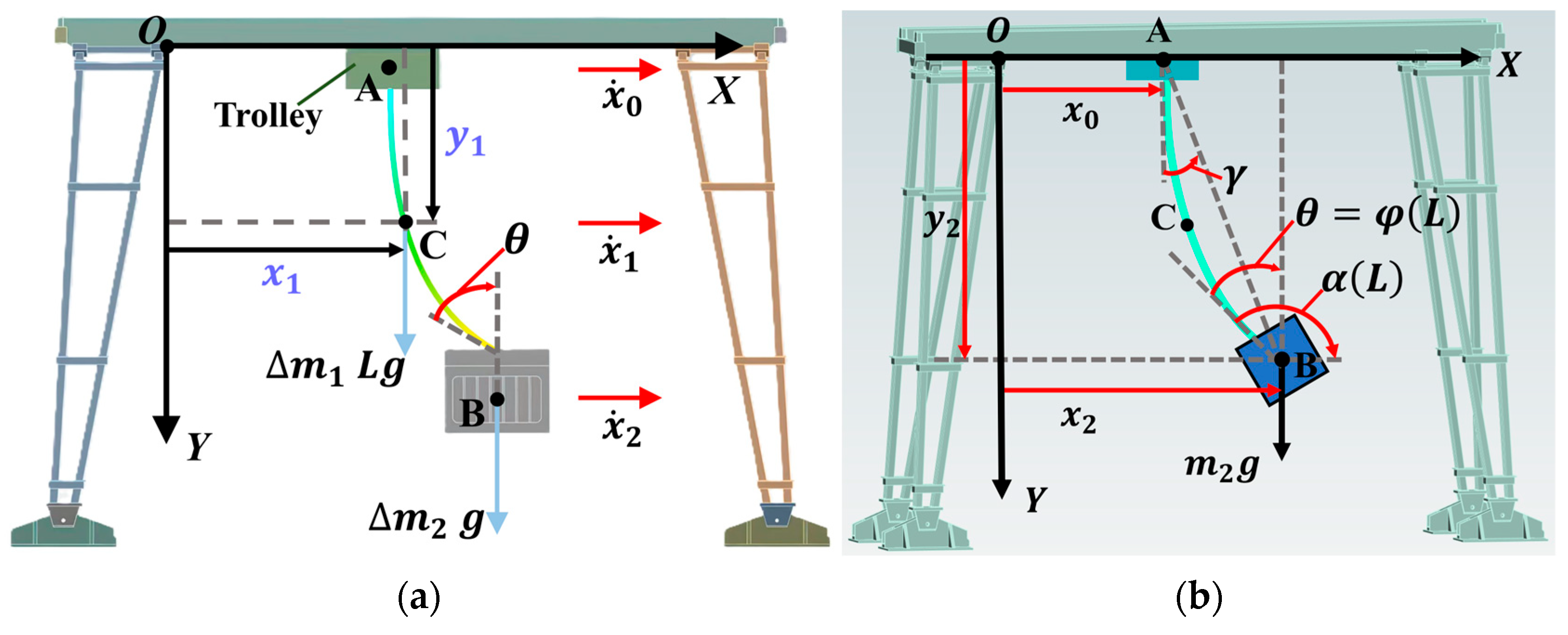
Figure 1. Schematic and dynamic models of the flexible cable crane hoisting system: (a) a schematic diagram of the hoisting battery pack; (b) the dynamic model of the flexible cable crane.
Actuators 14 00513 g001
Figure 2. Flexible cable force analysis diagram.
Actuators 14 00513 g002
Figure 3. Schematic of flexible cable cross-section and helical structure: (a) cross-sectional structure of cable; (b) initial pitch of outer wire in center strand; (c) initial pitch of outer wire in outer strand.
Actuators 14 00513 g003
Figure 4. Schematic of cable–pulley contact and force analysis: (a) front view of cable–pulley contact; (b) frictional contact area between cable and pulley; (c) force and geometric relationship of cable on pulley.
Actuators 14 00513 g004
Figure 5. Flow diagram of RAER control system.
Actuators 14 00513 g005
Figure 6. Dynamic model of rigid cable crane.
Actuators 14 00513 g006
Figure 7. Simulation results of velocity x ˙ 0 t .
Actuators 14 00513 g007
Figure 8. Simulation and experimental results of the motion angle of the flexible cable: (a) simulation results of γ in the flexible cable; (b) experiment results of γ in the flexible cable.
Actuators 14 00513 g008
Figure 9. Simulation results of horizontal motion under reference command: (a) simulation results of horizontal velocity under reference command; (b) simulation results of horizontal acceleration under reference command; (c) simulation results of horizontal displacement under reference command.
Actuators 14 00513 g009
Figure 10. Simulation results of vertical motion under reference command: (a) simulation results of vertical velocity under reference command; (b) simulation results of vertical acceleration under reference command; (c) simulation results of vertical displacement under reference command.
Actuators 14 00513 g010
Figure 11. Simulation results of velocity under damping: (a) simulation results of horizontal velocity under damping; (b) simulation results of vertical velocity under damping.
Actuators 14 00513 g011
Figure 12. Simulation results: (a) simulation results of the velocity at the upper endpoint; (b) simulation results of the acceleration at the upper endpoint; (c) simulation results of the displacement at the upper endpoint.
Actuators 14 00513 g012aActuators 14 00513 g012b
Figure 13. Simulation results of γ .
Actuators 14 00513 g013
Figure 14. Simulation results for energy cost W a c c t .
Actuators 14 00513 g014
Figure 15. Self-built overhead crane with suspension.
Actuators 14 00513 g015
Figure 16. Experiment results: (a) experiment results for trolley acceleration x ¨ 0 t ; (b) experiment results for trolley velocity x ˙ 0 t ; (c) experiment results for trolley displacement x 0 t .
Actuators 14 00513 g016
Figure 17. Experiment results for load swing angle γ t .
Actuators 14 00513 g017
Figure 18. Experiment results for energy cost W a c c t .
Actuators 14 00513 g018
Table 1. Performance indicators for analyzing effectiveness of simulation.
Control
Methods
γ m a x (deg) γ r e s (deg) t f (s) x ˙ 0 , m a x (m/s) x ¨ 0 , m a x (m/s2) W a c c (m2/s3)
Reference
common
9.428.452.930.500.500.50
ZV input
shaping
2.970.103.590.500.500.33
ZVD input
shaping
2.490.034.260.460.380.26
Smoother
shaping
1.810.084.600.400.300.16
RAER1.4305.580.350.250.12
Table 2. Performance indicators for experiments.
Control
Methods
γ m a x (deg) γ r e s (deg) t f (s) x ˙ 0 , m a x (m/s) x ¨ 0 , m a x (m/s2) W a c c (m2/s3)
Reference
Command
10.008.963.050.511.100.66
ZV input
shaping
3.300.313.900.500.890.49
ZVD input
shaping
2.640.134.250.470.710.34
Smoother
shaping
1.910.424.900.410.680.25
RAER1.600.035.580.360.390.16
Disclaimer/Publisher’s Note: The statements, opinions and data contained in all publications are solely those of the individual author(s) and contributor(s) and not of MDPI and/or the editor(s). MDPI and/or the editor(s) disclaim responsibility for any injury to people or property resulting from any ideas, methods, instructions or products referred to in the content.