Article

Numerical Investigation of a Morphing Wing Section Controlled by Piezoelectric Patches

1
Department of Civil and Industrial Engineering, University of Pisa, 56126 Pisa, Italy
2
Smart Material GmbH, 01159 Dresden, Germany
3
Baykar Piaggio Aerospace S.p.A., 17038 Villanova d’Albenga, Italy
4
C.I.R.A. SCpA, Italian Aerospace Research Centre, 81043 Capua, Italy
*
Author to whom correspondence should be addressed.
Actuators 2025, 14(10), 499; https://doi.org/10.3390/act14100499
Submission received: 29 August 2025 / Revised: 29 September 2025 / Accepted: 11 October 2025 / Published: 15 October 2025
(This article belongs to the Special Issue Aerospace Mechanisms and Actuation—Second Edition)

Abstract

One of the tasks of the FutureWings project, funded by the European Commission within the 7th framework, was to numerically validate the mechanical behavior of a wing whose deflections had to be controlled via a suitable distribution of piezoelectric patches. Starting from a reference geometry (a NACA 0012 airfoil), wing profiles were implemented and analyzed using the fluid–structure interaction analysis technique. The wing section was designed with a morphing profile in which both the front and rear parts self-deform via piezoelectric patches that serve actuators glued to the skin of the profile. A Macro Fiber Composite (MFC) was used as the piezoelectric actuator. Aeroelastic analyses were performed at low Mach numbers under the sea-level flight condition. Analysis of the technical solution was based on an examination of the aerodynamic coefficients and polar curves of the profile, as the control voltage of the patches can vary. The results were compared with those available in the literature. As a preliminary step, this work contributes to examining the current technical possibilities of this technology relating to the application of piezoelectric patches as actuators in the field of aerostructures.

1. Introduction

It is generally assumed that aircraft capable of smoothly and continuously changing shape (morphing) would offer optimized aerodynamic performance [1]. Recently, morphing wings have gained considerable attention due to advances in electronic components, such as smart actuators and compliant structures [2,3]. Morphing concepts have been developed with the objectives of weight and fuel consumption reductions and aeromechanical performance improvements compared to conventional aerostructures [1,2,3,4,5]. Only a few years ago, several critical aspects remained unresolved. Under this background, several studies were published to examine these critical issues in detail by identifying inventions and innovations, leading to both successes and failures [6].
Importantly, surface integrity must not be lost during flight [2]. This issue has been considered and critically examined in relevant projects by FlexSys [7], NASA [8], [9] (pp. 24–25), Airbus, Boeing, and other companies [9] (pp. 36–40). Polymorphic wings in small UAVs are capable of morphing their chords and curvature, achieving up to 10% chord extension and curvature morphing changes of +/−20% [10]. A system based on the use of “zigzag compliant ribs” and a pre-tensioned latex skin was also developed.
Morphing technology includes material selection and analysis, as well as analysis of the mechanical behavior of structures and the smart materials used for actuation and/or conventional actuators used for morphing. A fairly comprehensive review on this topic is provided in both [3,11]. For example, in [12], a study on morphing wing analysis and application, the authors addressed the real benefits of adopting morphing technologies considering practical aspects such as aircraft operation, mission planning, and sustainability.
Morphing wing designs, however, are challenging because the wing’s structure, skin, and actuators must be integrated to such a level that they all share the functions involved in carrying loads and changing shape.
Most previous research on morphing structures for aircraft applications involved twist-morphing or camber-morphing wings and tails, as well as adaptive leading and trailing edge technologies [12,13,14,15,16,17,18,19,20]. Camber-morphing is a type of out-of-plane morphing that bends the airfoil’s midline, thus changing the local lift distribution and essentially transforming a low-lift airfoil shape into a high-lift airfoil shape. Conventional aircraft use movable surfaces at the trailing edge to change the curvature of the wing sections in which they are installed, while camber-morphing surfaces provide a uniform shape without additional gaps, thereby reducing the strong drag produced by conventional control surfaces. The authors in [12] compared the aerodynamic performance of camber-morphing and conventional airfoils. This study demonstrated the advantages of variable camber-morphing wings over conventional wings in terms of their aerodynamic efficiency and maneuverability. In [13], the complete composite primary- and morphing-structure of a fixed-wing drone was additively manufactured for the first time. Studies have also been conducted on camber-morphing rib designs. The fish bone active camber concept (FishBAC), a biologically inspired compliant structure, was introduced in 2012 [18]. The airfoil deformation structure (which was novel and original at the time of this paper’s publication) consisted of a thin chordwise bending beam load-bearing structure with branched chords connecting the structure to a pre-tensioned Elastomeric Matrix Composite (EMC) skin surface. This solution was also adopted in [15], in which a shape-memory alloy (SMA) was used to actuate an unmanned aerial vehicle (UAV) tail structure. A CFD simulation of a camber-morphing airfoil in transition demonstrated that the aerodynamic behavior varies linearly as the camber rate rises [19]. Skin design also represents a significant challenge in wing morphing. A morphing skin is ideally a continuous surface that can adapt to the shape of the morphing body while remaining robust enough to withstand aerodynamic stresses. To meet these criteria, the skin must meet specific structural criteria such as low in-plane stiffness and high out-of-plane bending stiffness [15].
An in-depth study of different skin configurations was published in [21], focusing on the use of corrugated skin allowing large chordwise camber and length changes due to its high level of anisotropic properties. The authors in [22] investigated the multiaxial mechanical properties of a latex skin for morphing wing applications. In [23], the authors applied a fishbone variable camber wing in the design of a futuristic hybrid aquatic–aerial vehicle, obtaining technical results with numerical fluid–structure interaction (FSI) analyses.
Previous research on the performance of morphing technology has predominantly focused on the aerodynamics of specific morphing configurations [24,25] and calculating the deformation levels achievable with morphing techniques.
For example, in [24], the drag reduction benefits of wing morphing were quantified using numerical analysis techniques by comparing different curvature morphing rates with different conventional wing configurations created for different flap deflection angles. This study used different NACA0012 airfoil shapes, which differed only in curvature, while maintaining a constant thickness along the chord. The transformation from one airfoil shape to another was achieved by modifying the trailing edge (TE) and leading edge (LE), while the center section remained unchanged.
Altering the geometry of an aircraft wing during flight improves flight performance across a wide range of conditions. Conventional control systems such as flaps and ailerons introduce discontinuities on the wing surface, decreasing aerodynamic efficiency. In general, conventional wing-flap configurations do not provide an optimal solution for overall aircraft performance due to the different lift requirements under different flight conditions. Among the various methods, camber morphing has proven to be a highly effective and efficient approach to achieve optimal efficiency throughout the entire flight mission [24]. Furthermore, by using continuous, flexible skin enclosing ailerons and flaps, the noise generated by conventional wings can be significantly reduced.
In 1998, the Aircraft Morphing Program was started at NASA with the goal of developing morphing structures capable of changing shape using adaptive materials, microcontroller systems, and bioinspired material technologies to improve the aerodynamic efficiency of aircraft. The Morphing Aircraft Structure program worked on large-scale projects to build morphing flight vehicles capable of drastically changing shape during flight [8].
As already mentioned above, Woods and Friswell et al. [18] proposed the concept of a fish bone active camber wing. The idea of the fish bone active camber (FishBAC) is based on a flexible skeletal structure inspired by fish anatomy. Wind tunnel research [25] revealed that using the morphing FishBAC structure substantially improved the lift-to-drag ratio by 20–25% over a range of angles of attack, compared with a flapped airfoil. The work in [15] presents a new, simple, and lightweight SMA-based camber morphing wing design based on the FishBAC concept. In this study, according to the authors, the FishBAC model was integrated with SMA wire-actuated actuators running through the camber morphing ribs for the first time. A further example of this technique’s application can be found in [26], which applied a fishbone-like morphing wing rib design with rear spar articulation in a cost-effective manner.
The amount of camber in an airfoil has an important influence on the force generation under fluid flow. Variable camber structures often exploit this fact in fluid dynamics systems. The possibility of using variable geometry aerodynamic profiles is often included among the design choices subject to optimization processes [27].
In [28], a theoretical and experimental study, a morphing trailing edge concept, structure, and mechanism were designed, developed, and validated. This study examined the aeromechanical characteristics of a morphing airfoil section with the aim of achieving optimal aerodynamic efficiency while maintaining the same maximum lift coefficient. The experimental model used in this research included ribs matching the shape of a NACA 0012 airfoil with a chord 200 mm in size. The airfoil section featured a wingspan dimension of 250 mm. The trailing edge of the airfoil structure was effectively equipped with one rotational degree of freedom. To generate torque on the flap, an actuation system was installed. Using this system, the effective curvature of the airfoil could be changed by varying the produced lift. Additionally, variable trailing edge rotation angles from 0 to 30 degrees were considered in the study. However, this work did not consider the effects of the wing section skin, which was not actually superimposed onto the deformable internal structure of the section in the experimental model.
In [29], the deformation function and load capacity of the leading edge of a full-scale variable camber wing section were studied. An accurate mathematical model and a load test apparatus were also implemented. A distributed network of sensors was used to reconstruct the structural configuration during actuation of the leading edge. The motion function and structural strength of the leading edge structure of the variable camber wing section were then numerically estimated and validated using tests. In this work, no fluid dynamic analyses were conducted; only structural aspects related to use of the actuation mechanism producing deflection of the leading edge of the wing section were considered.
To our best knowledge, most morphing surface actuation systems in the literature are of the “mechanical” type, based on the use of linear actuators with significant power levels. Some studies also addressed new issues related to modification of the stiffness characteristics that can have effects on the aeroelastic stability of morphing wings [30].
One of the first examples of application of piezoelectric actuators was reported in [31], where this technology was applied to control deflection of the trailing edge of helicopter blades. Recently, other works have explored the use of piezoelectric materials for camber morphing [32]. In the present work, based on the application experiences described in other technical–scientific publications [33,34,35,36,37], we study an actuation method using piezoelectric patches installed directly on the outer skin of the aerodynamic surfaces to be deformed. This method could also be used to produce small amounts of electricity in stand-alone health monitoring systems [38,39]. In addition to these last applications, piezoelectric networks can also be exploited for structural vibration damping, as shown in [40,41]. This multifunctional potential further highlights the versatility of piezoelectric patches in morphing aerostructures.
In [42], a corrugated panel (a type of compliant periodic structure) used inside a morphing wingtip was studied numerically and experimentally. This type of structure could also be coupled with piezoelectric actuators.
In [43], a compliant morphing trailing edge was proposed and studied for the generation of high lift during take-off and landing. The design was characterized by enhanced aerodynamic performance and smaller take-off and landing distances due to its high lift capacity and intrinsic lightness compared to the basic configuration in conventional aircraft such as the ATR 72. This technical solution could further improve the performance of the Box-Wing Aircraft configuration, whose controllability was studied in [44] and take-off performance was studied in [45].
In [46], active hinged wingtips were analyzed to improve the gust load reduction and reduce the wing root bending moment, starting from the use of passive hinged wingtips, which increased the aspect ratio and provided additional gust attenuation.
In [47], the authors designed and aerodynamically analyzed the leading edge of a morphing wing. The variable camber leading-edge structure underwent numerical simulation validation (through FSI analyses) before its fabrication as an experimental prototype.
A recent line of research linked to the development of morphing structures is based on systematically studying the characteristics of lattice materials or metamaterials [48]. For example, in [49], a morphing wing was developed using mechanical metamaterials technology. The authors demonstrated that with the maturity of additive manufacturing technology, artificially designed mechanical metamaterial structures can offer very interesting mechanical properties. In this paper, a full lattice deformed wing based on mechanical metamaterials was proposed, and the wing model was analyzed from both structural and aerodynamic perspectives.
In the field of mechanical metamaterials, cells with negative Poisson’s ratios have also been applied to improve the deformability potential in morphing wings [50].
In [51], a lightweight camber morphing wing aircraft was designed, implemented, and tested in flight. This compliant camber-morphing wing configuration was proposed and implemented based on an in-depth computational analysis, with 3D-printed ribs used for the wing morphing mechanism. The wing skin of the small UAV was composed of a deformable material, and a single servomotor was used to power the rib’s morphing mechanism. Two connecting rods were connected to the servo (see Figure 9a of [51]), causing the front and rear parts of the rib to deform. Comparative analyses were also carried out using the NACA0012 profile as a reference, with a flap joint at 70% of the chord length.
Among the methods available in the literature on morphing wings [2,3], one of the technical concepts is based on the implementation of telescopic wings [52] or variable-span wings [4]. It is known that aircraft with a wider wingspan have good aerodynamic efficiency, which translates into good range and fuel economy.
In the field of methods and technologies used to design and produce morphing aerodynamic surfaces, a series of papers were published on the use of “Macro Fiber Composite (MFC), a type of piezoelectric device that offers structural flexibility and high actuation authority” [53,54,55,56,57]. Bilgen et al. [55] developed and successfully flight-tested an unmanned aircraft utilizing MFC actuators for solid-state control surfaces and effective roll control without traditional mechanical components. In this work, the researchers used NACA symmetrical airfoils as the leading edge blended with a thin trailing edge for morphing alongside tail stabilizer morphing using piezoelectric solid-state actuators. In a 2014 work by Bilgen and Friswell [56], NACA0012 profiles controlled with MFC were studied.
Chanzy et al. [58] employed a morphing wing technique featuring a flexible skin and variable camber mechanism, optimized for improved aerodynamic performance and validated through wind tunnel testing. As there was no hinge on the upper or lower surface of the wing, the proposed wing significantly reduced drag. This reduction yielded higher aerodynamic efficiency (lift to drag ratio: L/D) for morphing UAVs compared to conventional options, despite the lift force not experiencing significant enhancement.
Further examples of studies on morphing aerodynamic surfaces (winglets) can be found in [1,5]. In [5], the authors applied the camber-morphing winglet concept to a midsize business jet, showing that fuel consumption improvements can be achieved when compared to an optimized fixed geometry winglet.
The results of CFD calculations performed on a NACA airfoil by varying the curvature of the profile were presented in [14]. In this study, the CL-alpha curves of a self-deforming profile and conventional profile were compared, starting from a basic NACA0012 profile and modifying its curvature, thereby simulating the effects of a morphing technology. This work considered the effect of a control surface (flap) by varying the deflection angle. The study in [14] contains useful data that are compared in detail with the results of the present work, results which derive from some of the activities carried out within the European project FutureWings [59]. This project involved the companies Smart Material [60], Piaggio Aero Industries (today Piaggio Aerospace) [61], and IChrome [62] as partners, in addition to the University of PISA.
Almost simultaneously with the FutureWings project, other important projects were presented and developed within the European Community. Notable projects include the SADE project, the NOVEMOR project, and the SARISTU project [63,64,65,66].
An effective method for creating deformable airfoils involves the Kerf Bending Active Camber Concept [28]. The process of creating slots in a structural component (such as a rib) to facilitate bending is known as kerf bending. This method is applicable to a variety of materials, including metal. Using this technique, a wide range of shapes can be achieved. As previously mentioned, in [28], the NACA0012 profile was used as a reference for conducting morphing analyses, which is common among relevant studies in the literature.
Despite progress, one key problem remains: the compatibility of the deformations of profile skins with the deformations of the ribs, when such deformations change their curvature. This issue leads to the use of, e.g., highly deformable elastomeric materials. In the literature, some works have focused on exploring the deformation mechanism of morphing wing skin, although many analyses were purely numerical [67]. To resolve this technical problem, designs could adopt laser cutting techniques for morphing profile skins to facilitate their deformation capabilities [68].
Under this scientific and technical background, the present work describes a series of numerical results obtained with FSI analysis, applying an airfoil morphing technology based on the use of MFC-type piezoelectric patches.
This numerical analysis represents part of the preliminary work carried out within the FutureWings project [59]. This project aimed to numerically study a full-scale morphing wing model controlled via piezoelectric actuators.
Thanks to the availability considerable data, it is currently possible to perform an in-depth critical comparison of the results of our analysis.
Furthermore, it is possible to imagine studying new technical solutions that combine, for example, the adoption of Kerf-type structures with MFC-type piezoelectric actuators.

2. Materials and Methods

In this section, we describe the basic analysis of two-dimensional airfoils that can modify their aerodynamic shape via the use of MFC patches. The results for different flight conditions and hypothetical voltage distributions are also summarized. All the results are based on fluid–structure interaction analyses executed with a commercial software platform (ANSYS Workbench 15 [69]).
The present analyses utilize a nonlinear piezo-mechanical design coupled to the aerodynamic module of the code.
The preliminary aeroelastic analyses performed on two-dimensional wing sections are described to define the appropriate technical bases for subsequent and more complex three-dimensional analyses developed as part of the FutureWings project [59].
The results summarize the mechanical behavior of an airfoil section (i.e., the transformed section geometry in relation to the control parameters) and its aerodynamic performance, including polar drag curves of the airfoil section for different levels of control voltages, as well as different altitudes and Mach numbers.

2.1. Numerical Model of a Piezo-Controlled NACA0012 Wing Section

2.1.1. Finite Element Structural Model of the Wing Section

A piezo-actuated wing section created with the geometry of an NACA0012 airfoil (chord = 600 mm, width = 57 mm) was analyzed. The section width corresponds to the maximum active width of the MFC patches (commercial code M8557-P1 [60]). The wing section geometry is shown in Figure 1. Here, the nose is 20% of the chord, the wing box is 35% of the chord, and the trailing edge is 45% of the chord. The original profile was cut for TE morphing modeling. For practical reasons, the profile at the trailing edge was slightly truncated by about 2 cm, as shown in the figure. The length of the chord shown in the figure is nominal.
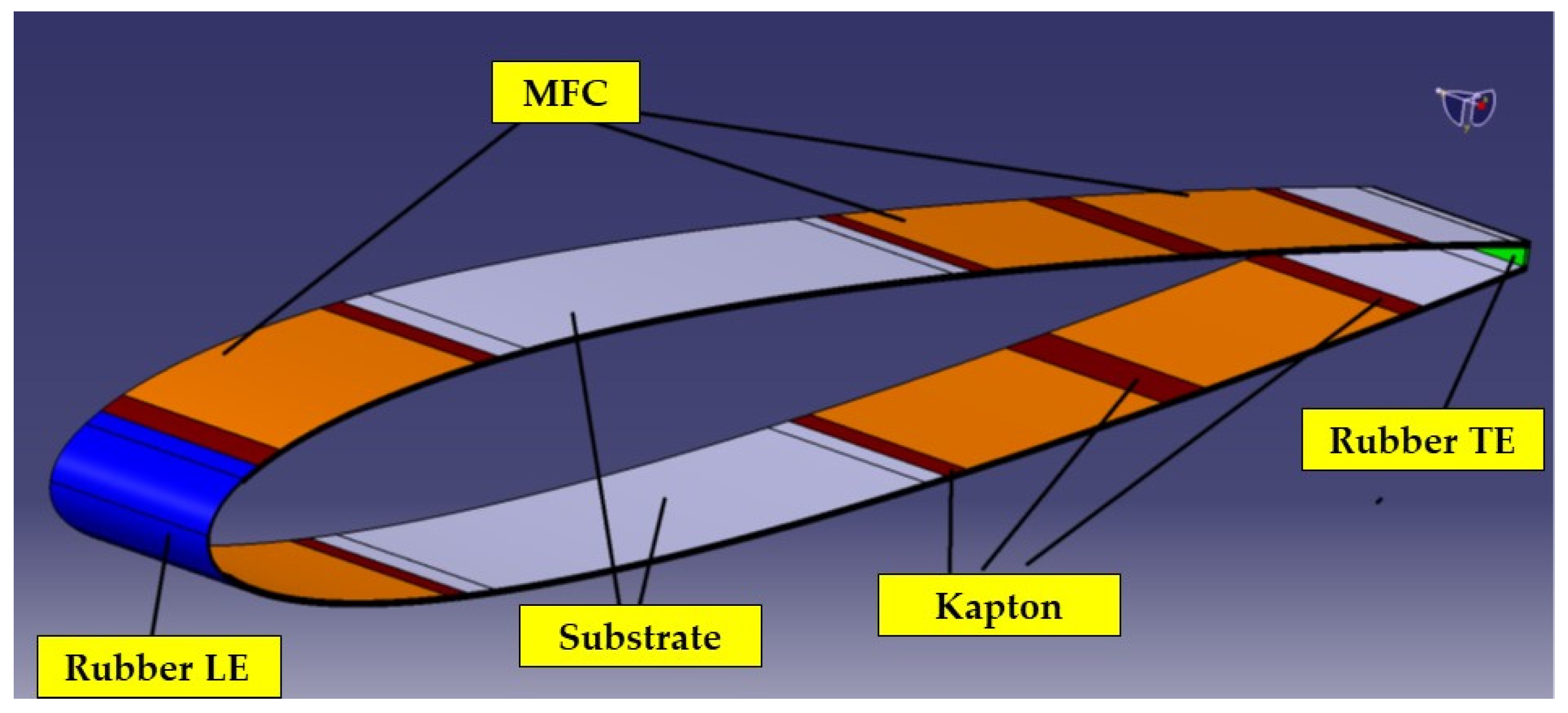
In this preliminary phase of the study, a series of fluid–structure interaction analyses was performed. The structural model of the wing section is composed of a composite material substrate (4-ply Graphite/Epoxy fabric, stack orientation 45°/0°/0°/−45°, with an overall thickness of 1 mm) with piezoelectric patches that deform both the leading and trailing edges under a voltage input. The MFC patches, modeled with the characteristics of an orthotropic material, are glued to the structure using resin and installed on the external and internal surfaces of the nose and tail laminates. In this way, the patches can simulate the effects of the moving surfaces of a wing. Separation between the two patches was achieved using Kapton (dark brown stripes in Figure 2 and Figure 3).
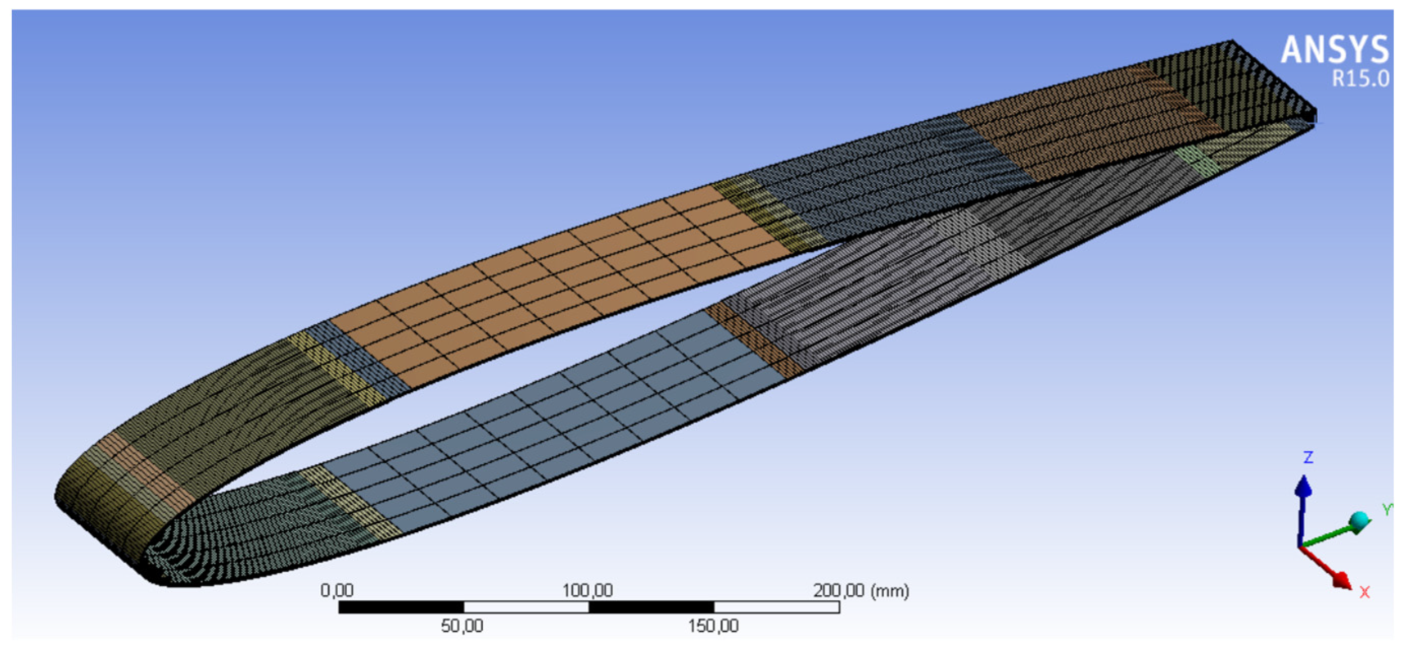
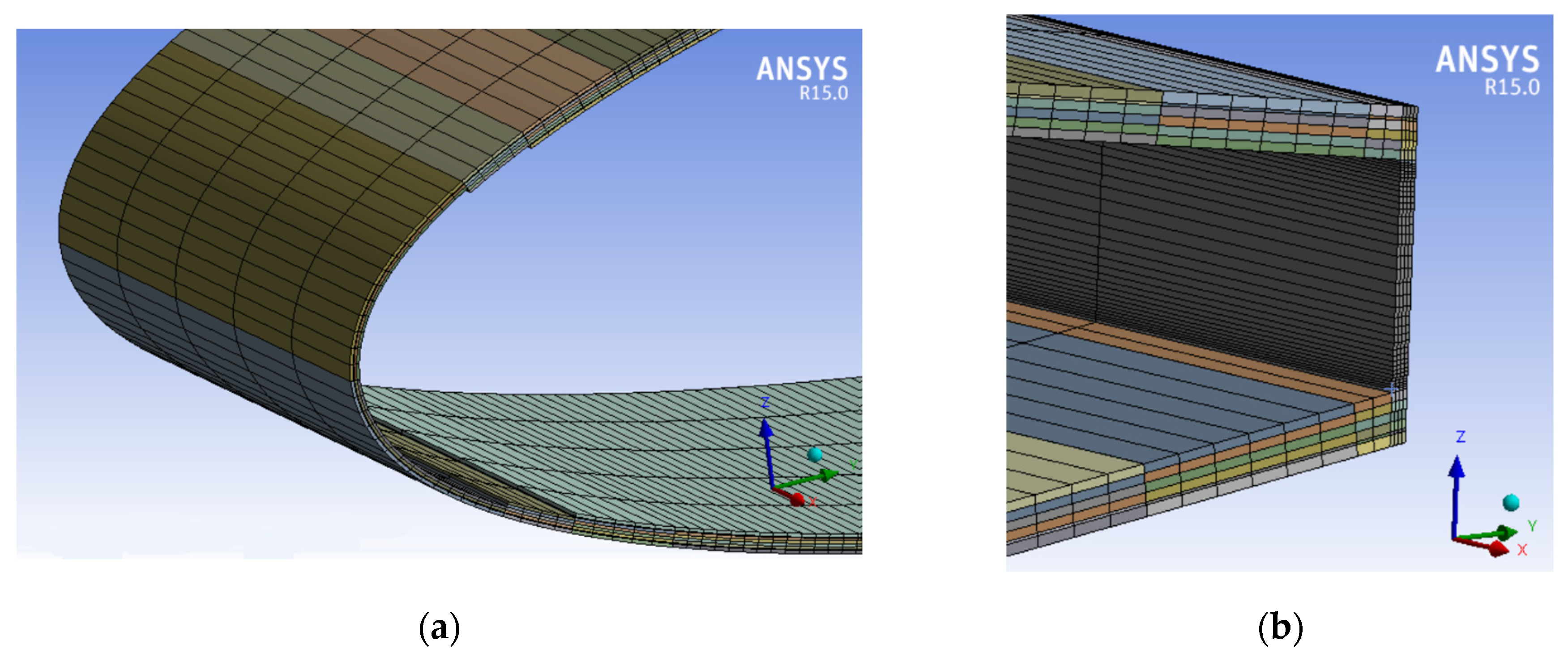
In the geometric environment, all bodies are connected as a unique part to avoid using connections in a mechanical environment. The ANSYS elements used in these analyses are SOLID186 and SOLID226. To define the piezoelectric material, a command script was inserted. The mesh is particularly dense in the LE and TE zones but coarser in the wing box region (see Figure 4 and Figure 5).
Table 1 shows the thickness of each component of the profile model. Table 2 summarizes the data on the materials used in this analysis. The substrate data were defined via experimental measurements specifically carried out during development of the project (graphite/epoxy KGBX2508). The parameters C 10 (and C 01) are used in the Mooney–Rivlin model to simulate rubber-like materials.
By exploiting the physical behavior of the MFC studied in the first part of the project [33], deformation of the nose and tail of the wing section was produced. We obtained the desired deformed shape of the wing section without using high voltage values by loading the outer surface of the upper skin and inner surface of the lower skin with a positive electrical voltage and the inner surface of the upper skin and outer surface of the lower skin with a negative voltage; we also set the positive voltage equal to three times the negative voltage. As shown in Figure 4 and Figure 5, hexahedral brick elements SOLID186 were used to model the entire profile (quadratic option), including the substrate (fabrics), bonding resin, and MFC passive volumes. Piezoelectric elements SOLID226 were used for the MFC active volumes. Here, the total number of nodes is equal to 32,082, and the total number of elements is 23,420. The geometric nonlinearity (large displacements) option was activated for this analysis.
The boundary conditions applied to the FE model assume that all displacements of the lateral edges of the central part (wing box) of the wing section are fixed. On the lateral edges of the rest of the profile, only the displacements in the out-of-plane direction are fixed. This process essentially simulates two-dimensional behavior.
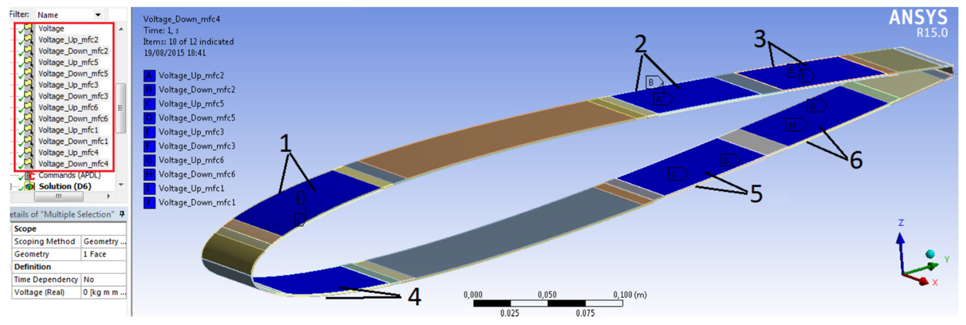
To define the potential loads, we used the Ansys add on, with which the user can choose the surface of the body and insert the correct voltage value. We obtained the desired deformed shape of the wing section without using high voltage values by loading the outer surface of the upper skin and inner surface of the lower skin with a positive electrical voltage. We also used a negative voltage on the inner surface of the upper skin and outer surface of the lower skin, setting the positive voltage equal to three times the negative voltage. All the MFC surfaces in contact with the substrate were loaded with zero voltage. In this analysis, a reference voltage V* = 900 V was assumed, which will be used to produce a parametric representation of the results. Table 3 summarizes all analyzed cases, where cases 0 through 3 are realistic. On the other hand, cases 4 through 7 are hypothetical, as they use voltage values that commercial patches cannot support. The maximum applicable positive operating voltage is 1500 V, while the minimum applicable negative voltage is −500 V [60].
Figure 6 shows the adopted nomenclature for the patches and the Ansys commands used to define the voltage loads. As mentioned above, the large displacements option was applied. Ten iterations were used for each load step using force-based convergence criterion, with a residual value equal to 0.5%.

2.1.2. Fluid Dynamic Model of the Wing Section

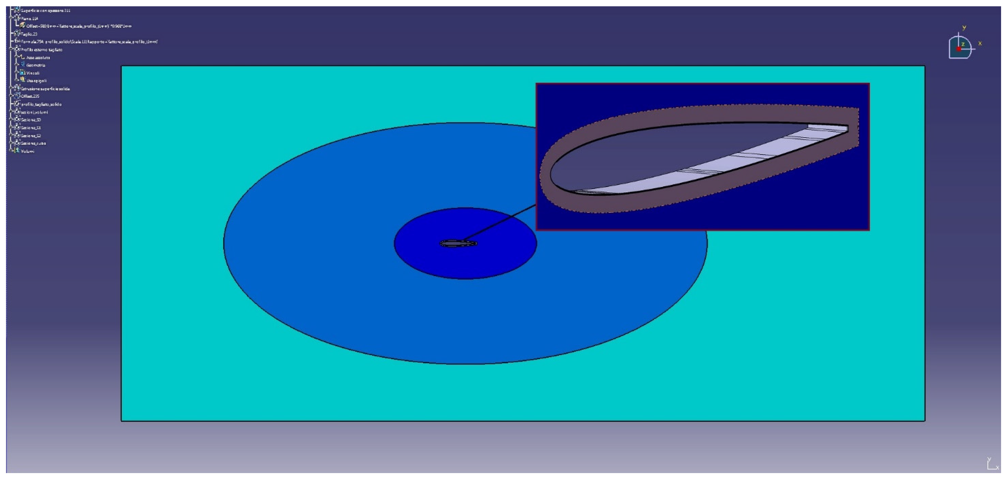
To perform coupled fluid–structure analyses, we used the System Coupling module implemented in ANSYS Workbench. This module manages unidirectional and bidirectional force-displacement couplings between the ANSYS Fluent and ANSYS Mechanical software to perform FSI simulations. This coupling system enables solutions for steady-state or transient FSI applications to be derived entirely within Workbench. This module also handles many complex FSI applications, such as the flutter of three-dimensional airfoils or wings, flow-induced vibrations, and more. After defining the structural model, the model’s geometry was managed using CAD software (CATIA V5R20 [71]) to operate on the external region that will be occupied by the fluid domain, without modifying the shape of the external surface of the profile (Figure 7).
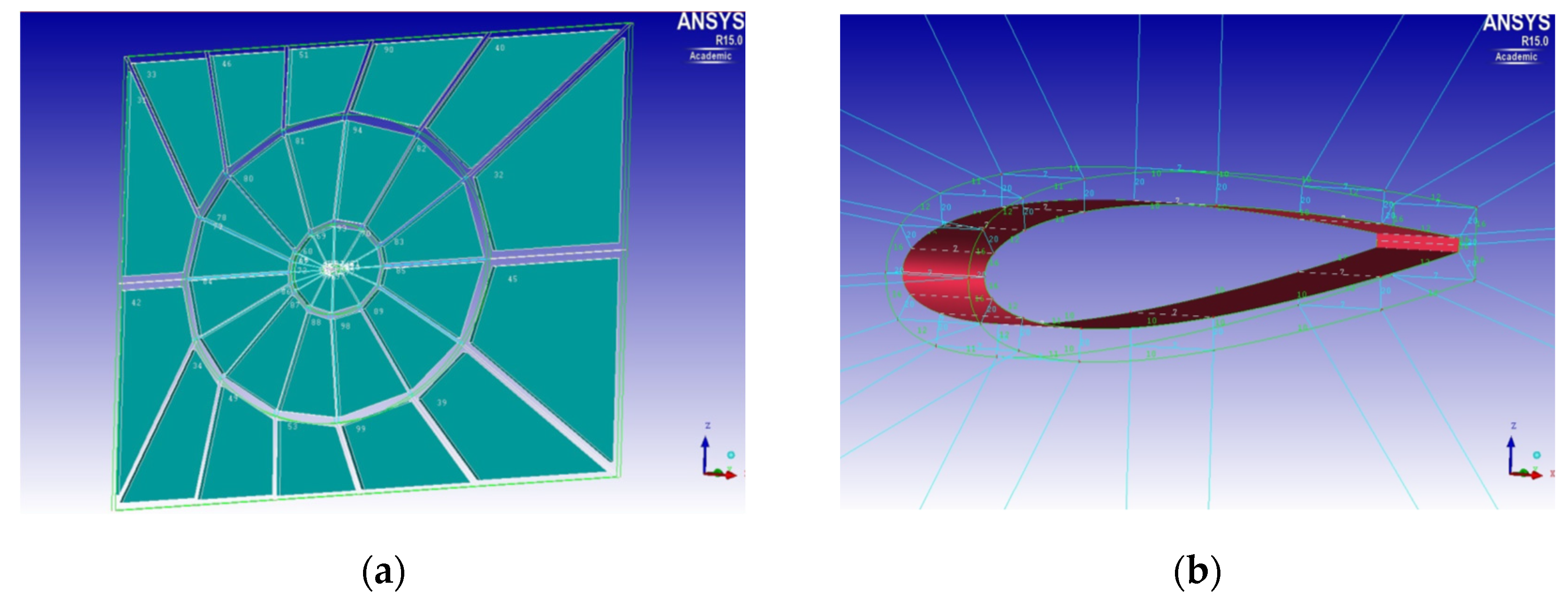
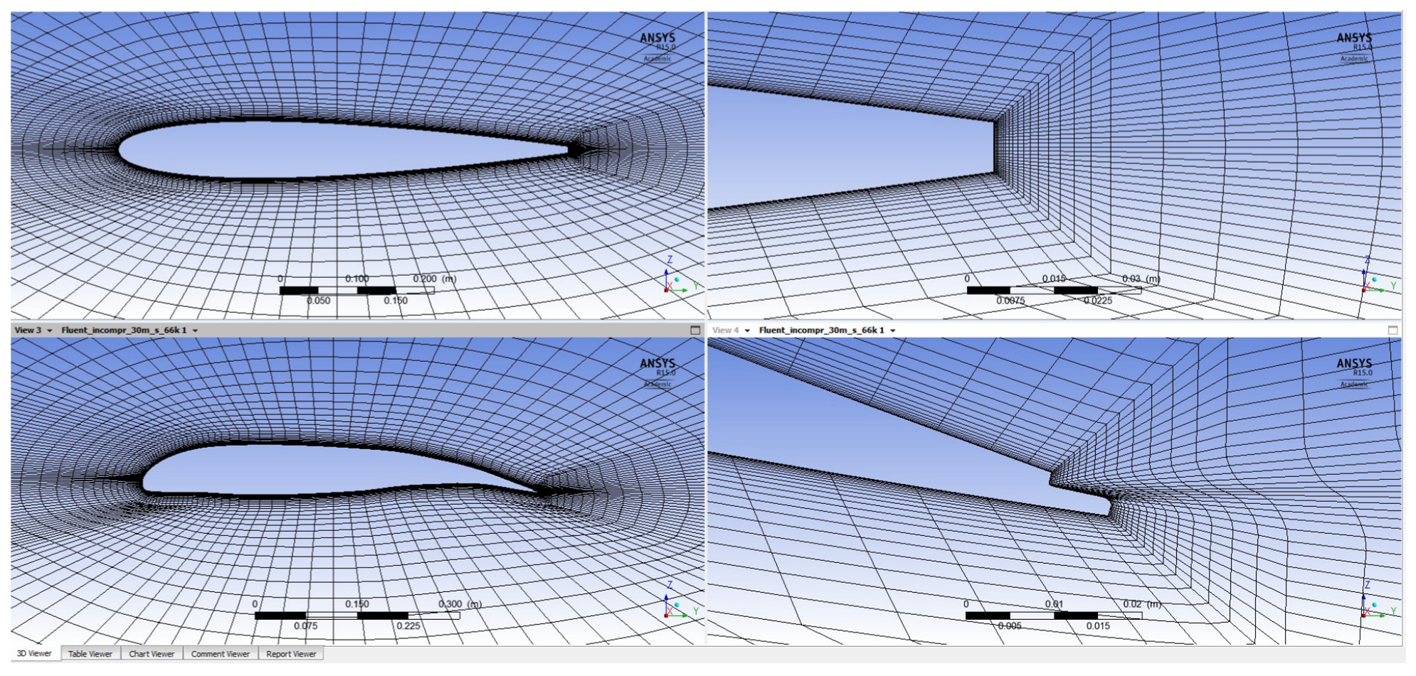
Figure 8 shows the block model, which divides the fluid region into a set of connected subregions where the number of nodes, spacing ratio, and direction of propagation of the node spacing can be easily controlled. A parametric fluid dynamic grid composed only of hexahedral cells was generated to optimize the dynamic mesh standards.
This procedure generated a fluid mesh composed of 55,680 hexahedral cells for a total of 66,080 nodes. This volumetric mesh is delimited by several surface meshes to introduce the appropriate boundary conditions. This model is effectively three-dimensional and uses brick elements to correctly model the piezoelectric patches using ANSYS software. However, symmetric flow conditions were imposed on the lateral edges of the airfoil section to reproduce the results obtained with a two-dimensional airfoil. Figure 9 shows the generated fluid dynamic grid. To carry out fluid dynamic analyses, we used the FLUENT software (available within the Workbench platform).
The analyses were performed under the following flight conditions: at sea level (h = 0 m), with an asymptotic speed V = 30 m/s and four different values for the angle of attack (α = 0°, 2°, 4°, and 6°).
The table in Figure 10 shows the parameters used to perform the fluid dynamic analyses. In Figure 10, the Reynolds number for the various analyses is approximately equal to Re = 1.2 × 10⁶.

3. Results

To perform fluid–structure interaction analyses, the “dynamic mesh” option was used to make the deformations of fluid cells consistent with those of the wing surface. More specifically, the “Smoothing-Spring/Laplace/Boundary Layer” command [69] was used, which allows the motion of the nodes to be calculated based on the static stiffness of the fluid in each cell, assuming that the motion is inversely proportional to the characteristic size of the cells themselves. The “deform adjacent boundary layer with areas” option was also used since the model assumes shapes that deviate significantly from the initial ones under the deformations produced by the actions of the piezoelectric patches. This phenomenon occurs primarily around the rubber connection areas, i.e., near the leading and trailing edges.
The method used increased the convergence rate, significantly reduced the cell deformation effect, and ensured the reliability of the results.
Figure 11 shows an example of the undeformed dynamic mesh and the dynamic mesh deformed using only the voltage command applied to the patches (Case 7 in Table 3), i.e., without considering the effects of aerodynamics.

3.1. Deformations and Aerodynamic Coefficients of the Morphing Profile

In a complete FSI analysis, the structural and fluid dynamic modules exchange data iteratively. They update the data based on nodal loads, from fluent to mechanical, and displacements, from mechanical to fluent. In this way it is possible to obtain the values of the lift coefficient (Cl) and drag coefficient (Cd) for different voltage loads and angles of attack.
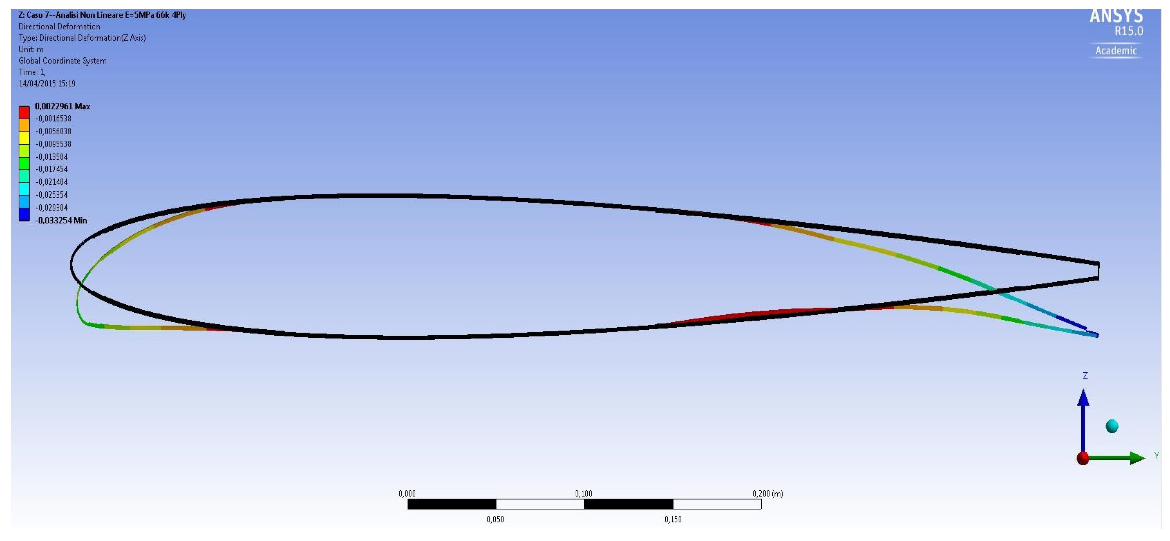
Figure 12 shows full-scale deformation of the airfoil section corresponding to Case 2 in Table 3 and α = 0° (FSI results), while Figure 13 shows full-scale deformation of the airfoil section corresponding to Case 7 in Table 3 and α = 0° (FSI results). Mechanical analyses assume that the central part of the section is constrained and, therefore, does not translate or rotate under the action of aerodynamic forces.
The physical conditions of the aerodynamic flow examined are summarized in Figure 10.
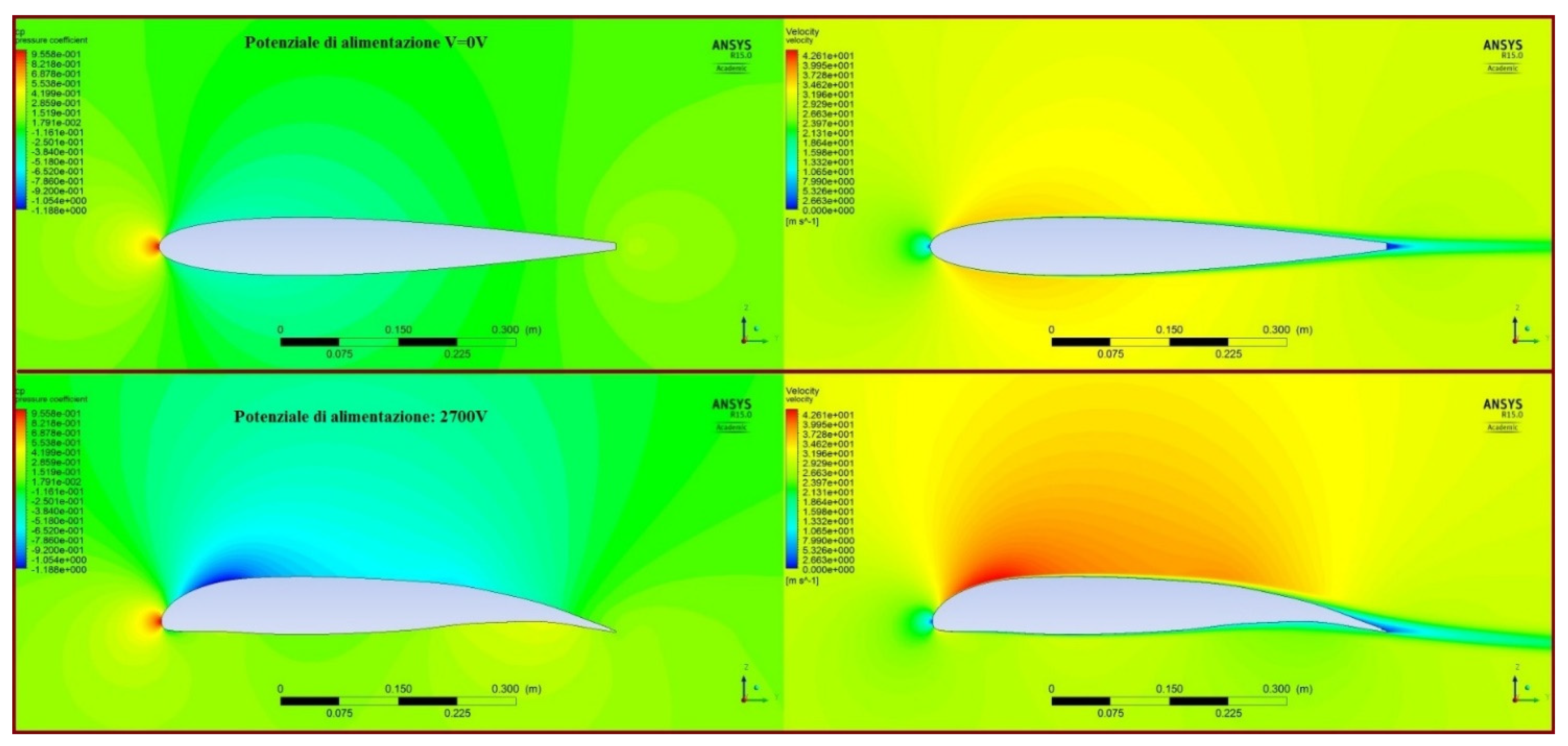
Figure 14 shows the pressure coefficient (Cp) distributions (left) and velocity fields (right) for h = 0 m, α = 0° and voltage loads corresponding to Case 0 and Case 7 in Table 3. The Cp approaches an acceptable approximation of a unit value at the leading edge of the profile.
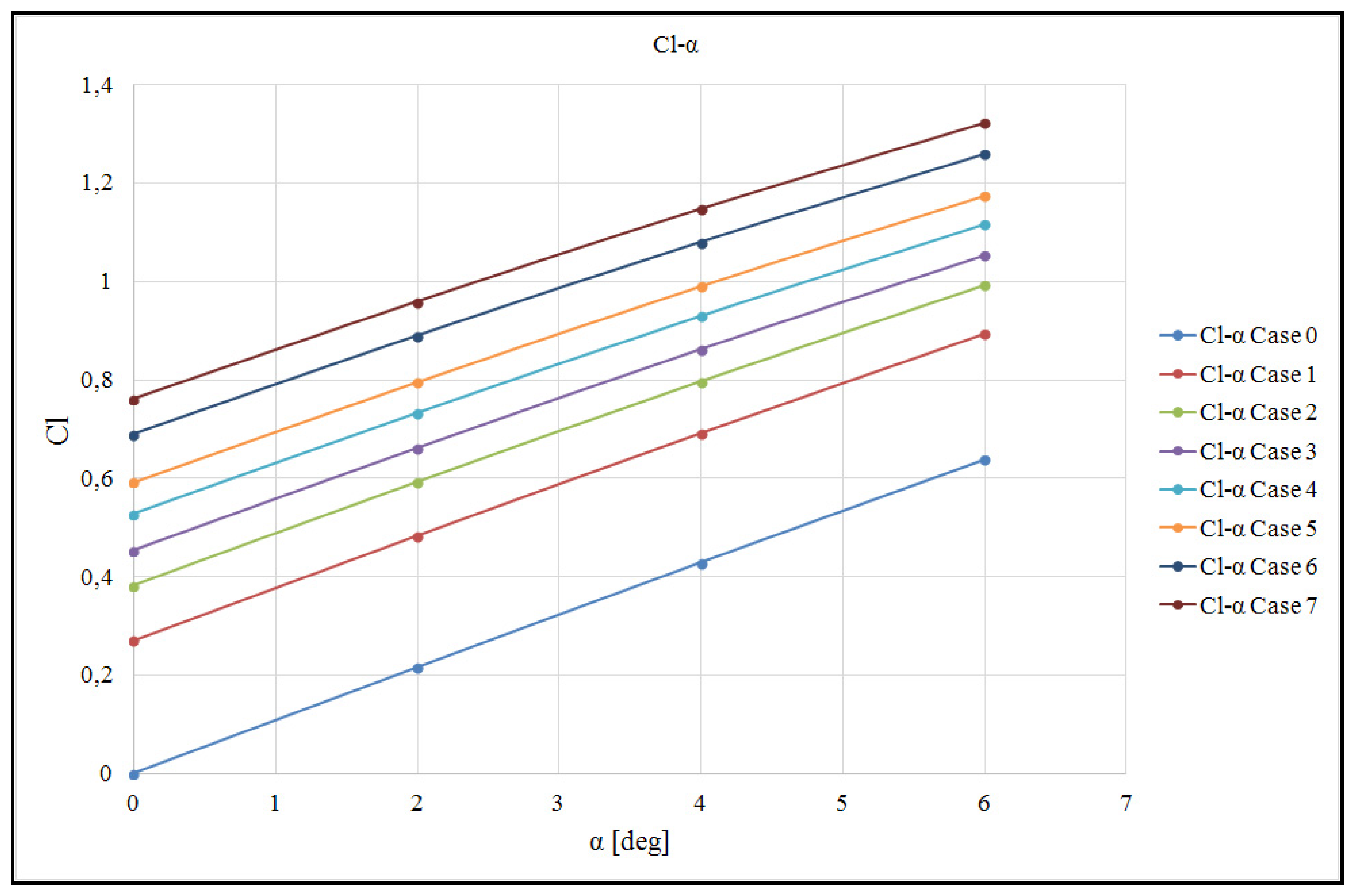
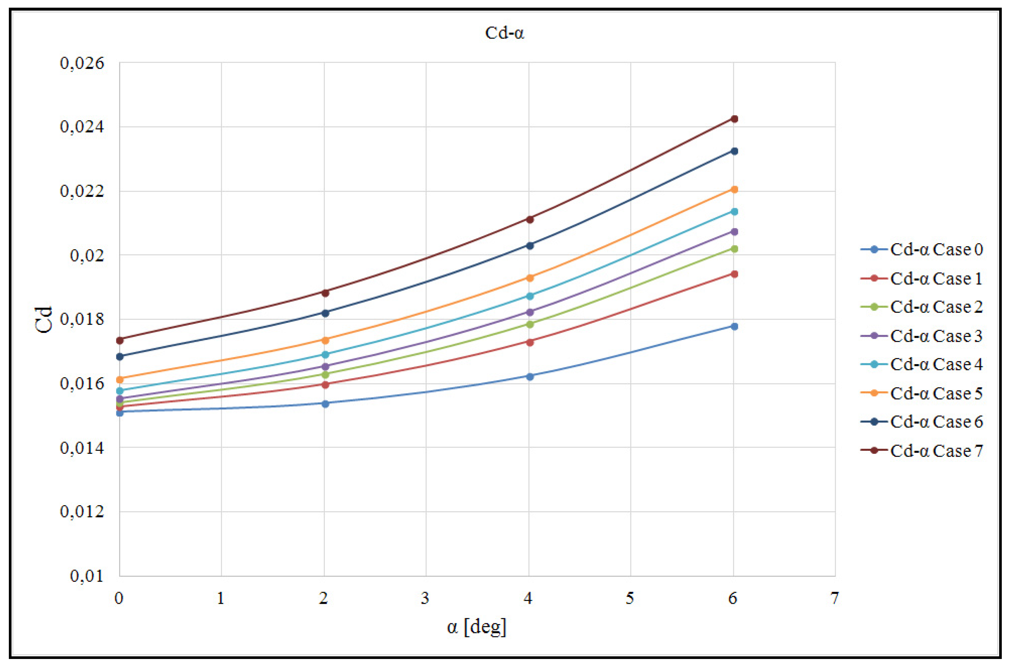
Figure 15, Figure 16, Figure 17 and Figure 18 show the Cl-α, Cd-α, and Cl-Cd polar curves and Cl-V curves, respectively, for the analyzed NACA0012 wing section.

3.2. Comparison of Results in Terms of Calculated Aerodynamic Coefficients

We compared the present results to those reported in [14]. This work considered both the effects of a traditional flap and the effects of variation in the curvature of a basic profile coinciding with NACA0012. Notably, the Reynolds numbers in the present analyses and those presented in [14] are not perfectly comparable (about 1,200,000 versus 77,000). Nevertheless, while such a difference can have an important effect on the drag coefficients, it remains less important in calculating the lift coefficients.
An initial comparison of the lift coefficient for the basic profile using an angle of incidence of 4 degrees (Figures 7 and 8 in [14]) obtained values with excellent agreement. The Cl was approximately 0.4 in both [14] and the present results, as shown in Figure 15.
Figure 8 in [14] presents results for the deflection of a conventional flap. Here, Cl = 0.67 was estimated for an incidence of 4 degrees and a flap deflection of 4.5 degrees. This result compares well with the results in Figure 15 (Case 1 in Table 3), which provides a Cl of approximately 0.7.
Similarly, for a flap deflection of 9.5 degrees with the same incidence of 4 degrees (Figure 8 in [14]), a Cl of about 0.89 was estimated. For comparison, Case 3 (Table 3) in our study yielded a Cl of approximately 0.86.
Notably, both cases considered so far (Case 1 and Case 3) refer to voltage levels realistically applicable to piezoelectric patches.
Directly examining the data from Figure 10 in [14] relating to the morphing profiles demonstrates that Case 3 in our study can be directly compared with the 5412 profile, which provides a Cl = 0.86 for an incidence angle of 4 degrees.
Further, the 6412 morphing profile from Figure 10 in [14], which estimates a Cl of approximately 0.93, is comparable to that of Case 4 in Table 3 (Cl = 0.94 see Figure 15). In our study, however, the voltage load applied to the patches was higher than what can be realistically applied.
Table 4 and Table 5 summarize the possible comparisons between the results reported in [14] and the results of the present work. For example, here, an angle of attack α of 4 degrees was considered. In Table 4, the flap deflection angle is indicated with the symbol β.
Another less-precise comparison was conducted by comparing the polar curves of the profile studied here with those from Figure 9 in [18]. Although purely theoretical from the perspective of applied voltage levels, the polar curve corresponding to Case 7 in Table 3 overlaps well with the polar curve corresponding to the FishBAC configuration in [18] (deflection coefficient: k = 0.3), based on the range of available Cl and Cd values. A similar comparison was made with the results from Figure 8b in [24], which presents the polar curves of the basic NACA0012 profile together with those from a series of morphed profiles. The data in Figure 17 of our work agrees well with the graphical summary in [24].
We also directly compared the application of morphing technology like that explored in the present study, despite the different configuration and distribution of MFC piezoelectric patches, by examining the work in [55]. In particular, we compared the graph from Figure 8a in [55] with a curve corresponding to α = 0°, reproduced here in Figure 18. Figure 8a in [55] presents the results for the lift coefficient of an NACA0012 airfoil as a function of the applied voltage obtained via a static aeroelastic analysis with a flow velocity of 20 m/s. For example, for an applied voltage of about 900 V (V/V* = 1), a Cl value equal to about 0.4 is obtained in both cases.
The present results and comparisons, the latter of which are not always quantitatively precise, show that technology based on the application of piezoelectric patches offers technically interesting properties, at least from the perspective of wing profile aerodynamic performance.
As demonstrated in some of the previously cited works, use of this technology in the development of medium- to small-sized UAVs, coupled with the development of specific compliant structures such as the Kerf Bending Active Camber Concept, could produce even greater performance than that numerically obtained in this research.

4. Discussion

A comprehensive review of the work carried out and presented in this study reveals that the present application of morphing technologies in the aerostructures sector has achieved a high level of resonance. In the literature, most technical applications refer to complex mechanical systems and inevitably have low levels of reliability.
In this paper, which is part of the research conducted under a European project [59], we examined a technology based on the use of MFC-type piezoelectric patches applied directly to the skin of an airfoil. To evaluate the feasibility of this technology, an NACA0012 airfoil was examined.
The airfoil, without internal shear reinforcements, structurally included only top and bottom skins, both made of a thin composite laminate.
The numerical study was based on the development of coupled fluid–structure calculations to simulate the electromechanical effects of the patches. Using these calculations, we obtained data on the aeromechanical performance of an airfoil for aeronautical applications, including the aerodynamic coefficients and polar curves.
The primary goal of this work was to correlate the voltage levels applied to the piezoelectric patches with the aerodynamic coefficients for given aerodynamic flow conditions.
Each point shown in Figure 15, Figure 16, Figure 17 and Figure 18 corresponds to the result of a single static aeroelastic analysis performed on the wing section model.
We examined angles of attack ranging from zero to 6 degrees. The results, therefore, reflect fairly regular flow conditions, i.e., with no marked separation phenomena at the trailing edge of the profile. This regularity is demonstrated by the almost perfect linearity of the lift coefficient Cl under a varying alpha value (Figure 15).
The effects of the voltage loads (from Case 0 to Case 7) are clear. Increasing the profile curvature at the same angle of attack produces an increase in lift (increase in Cl, Figure 15) and, correspondingly, an increase in aerodynamic drag (increase in Cd, Figure 16). The polar curves are affected by these combined increases, as shown in Figure 17.
Finally, our calculation technique allowed us to directly quantify the effects of the power supply potential of the patches at equal incidence, in accordance with the definition of the reference potential and the distribution of electrical loads applied to the patches, as shown in Table 3.
Figure 18 summarizes the Cl trends as the feed potential varies. The curves show a bilinear shape, likely due to variation in the external geometry of the profile, which is clearly affected by its initial shape. This result is also visible in Figure 15, where the Cl-α curves become increasingly closer as the index increases, despite being perfectly linear.
Notably, in the static aeroelastic analyses performed using FSI, some hypothetical loading conditions were considered, i.e., the use of voltage values higher than those permissible for commercially available MFC patches (Case 4 to Case 7 in Table 3). These theoretical analyses were conducted to verify the feasibility of applying this technology. However, if patches with very high electro-mechanical performance were available, the proposed technology would become much more efficient than other technologies based on purely mechanical deformation systems.
Ultimately, the results obtained in this work are in good agreement with the literature and also offer some novel data, especially regarding the type of material used to manufacture the substrate (profile skins), which is not elastomeric but offers fairly high extensional and flexural stiffness. An elastomeric material was used only at the leading and trailing edges of the profile (Figure 2).

5. Conclusions

In this work, which summarizes research conducted as part of a European project [59], a numerical model was developed to perform a feasibility study on applying piezoelectric patches of the MFC type to airfoils in order to continuously modify their shape. An NACA0012 airfoil with a nominal chord size of 600 mm was studied. In reality, the effective chord was slightly reduced by about 20 mm to enable consistent modeling of the trailing edge of the airfoil. Both model preparation and the numerical analysis were performed using commercial software [69,71].
The supporting substrate of the skins was made using a stiff carbon fiber laminate. No internal support structures, such as ribs, were modeled. The leading edge and trailing edge were modeled with an elastomeric material sufficiently flexible to facilitate the flexural deformation of the skins.
Some MFC patches [60] were glued onto both the upper and lower skins.
Coupled fluid–structure analyses were performed to consider the effects of aerodynamic loads combined with the effects of voltage loads applied to the piezoelectric patches. The results mainly relate to the aerodynamic coefficients of the loaded profile.
The studied morphing technology produced results in good agreement with results in the literature. A detailed and quantitative comparison was also performed on the calculated lift coefficients [14], along with some qualitative comparisons on the profile polar curves [18,24] and the effects of the voltage loads applied to the patches [55].
Based on the extensive literature reviewed, morphing technologies currently rely primarily on the application of mechanical actuation systems. These systems are generally very complex, consisting of many mechanical elements, and heavy. The use of piezoelectric paths does not yield very high deformation levels due to the physical limitations of current patches on the market. However, the present simulations and results demonstrate that potential developments in piezoelectric materials with higher performance, e.g., a wider load potential range, could offer remarkable aeromechanical performance even for medium-sized aircraft, not just the small aircraft commonly studied in the literature.
We believe that by coupling the technology discussed in this study with the structural configurations in the literature (Kerf Bending Active Camber Concept [28]), it is possible to increase the aeromechanical performance of airfoils thanks to a greater increase in the curvature of the airfoils’ mean line. Possible future development of this work could involve designing and modeling a Kerf structure that deforms under the action of MFC patches appropriately positioned on the transverse elements of the structure itself.

Author Contributions

Conceptualization, M.R.C. and V.B.; methodology, M.R.C., S.B. (Salvatore Bonomo), S.B. (Stefano Botturi) and L.G.; software, S.B. (Salvatore Bonomo), S.B. (Stefano Botturi) and L.G.; validation, M.R.C., V.B., J.K., A.C. and D.G.R.; formal analysis, S.B. (Salvatore Bonomo), S.B. (Stefano Botturi) and L.G.; investigation, M.R.C. and V.B.; resources, M.R.C. and V.B.; data curation, S.B. (Salvatore Bonomo), S.B. (Stefano Botturi) and L.G.; writing—original draft preparation, M.R.C., S.B. (Stefano Botturi) and L.G.; writing—review and editing, M.R.C.; project administration, M.R.C. and V.B.; funding acquisition, M.R.C., J.K. and A.C. All authors have read and agreed to the published version of the manuscript.

Funding

The research leading to these results received funding from the European Research Council under the European Union’s Seventh Framework Programme: Grant Agreement No. 335042.

Data Availability Statement

The original contributions presented in this study are included in the article. For further information, please contact the authors.

Conflicts of Interest

Author Jan Kunzmann was employed by the company Smart Material GmbH. The remaining authors declare that the research was conducted in the absence of any commercial or financial relationships that could be construed as a potential conflict of interest.

Abbreviations

The following abbreviations are used in this manuscript:
MFCMacro Fiber Composite
FishBACFish Bone Active Camber Concept
FSIFluid–Structure Interaction
EMCElastomeric Matrix Composite
SMAShape-Memory Alloy
UAVUnmanned Aerial Vehicle
CFDComputational Fluid Dynamics
TETrailing Edge
LELeading Edge

References

  1. Kaygan, E. Aerodynamic Analysis of morphing winglets for improved commercial aircraft performance. J. Aviat. 2020, 4, 31–44. [Google Scholar] [CrossRef]
  2. Barbarino, S.; Bilgen, O.; Ajaj, R.M.; Friswell, M.I.; Inman, D.J. A review of morphing aircraft. J. Intell. Mater. Syst. Struct. 2011, 22, 823–877. [Google Scholar] [CrossRef]
  3. Li, D.; Zhao, S.; Da Ronch, A.; Xiang, J.; Drofelnik, J.; Li, Y.; Zhang, L.; Wu, Y.; Kintscher, M.; Monner, H.P.; et al. A review of modelling and analysis of morphing wings. Prog. Aerosp. Sci. 2018, 100, 42–62. [Google Scholar] [CrossRef]
  4. Santos, P.; Sousa, J.; Gamboa, P. Variable-span wing development for improved flight performance. J. Intell. Mater. Syst. Struct. 2017, 28, 961–978. [Google Scholar] [CrossRef]
  5. Eguea, J.P.; Pereira Gouveia da Silva, G.; Martini Catalano, F. Fuel efficiency improvement on a business jet using a camber morphing winglet concept. Aeros. Sci. Tech. 2020, 96, 105542. [Google Scholar] [CrossRef]
  6. Weisshaar, T.A. Morphing aircraft systems: Historical perspectives and future challenges. J. Aircr. 2013, 50, 337–353. [Google Scholar] [CrossRef]
  7. FlexSys Inc. 2025. Available online: https://www.flxsys.com (accessed on 1 January 2025).
  8. Wlezien, R.W.; Homer, G.C.; McGowan, A.R.; Padula, S.L.; Scott, M.A.; Silcox, R.J.; Simpson, J.O. The aircraft morphing program. In Proceedings of the 39th Structures, Structural Dynamics, and Materials Conference and Exhibit, Long Beach, CA, USA, 20–23 April 1998; AIAA Paper 98-1927. Available online: https://ntrs.nasa.gov/citations/19980053567 (accessed on 6 September 2013).
  9. Concilio, A.; Dimino, I.; Lecce, L.; Pecora, R. Morphing Wing Technologies: Large Commercial Aircraft and Civil Helicopters; Butterworth-Heinemann, an Imprint of Elsevier: Oxford, UK, 2018; ISBN 978-0-08-100964-2. [Google Scholar]
  10. Parancheerivilakkathil, M.S.; Ajaj, R.M.; Khan, K.A. A compliant polymorphing wing for small UAVs. Chin. J. Aeronaut. 2020, 33, 2575–2588. [Google Scholar] [CrossRef]
  11. Zhu, J.; Yang, J.; Zhang, W.; Gu, X.; Zhou, H. Design and applications of morphing aircraft and their structures. Front. Mech. Eng. 2023, 18, 34. [Google Scholar] [CrossRef]
  12. Jo, B.W.; Majid, T. Enhanced Range and Endurance Evaluation of a Camber Morphing Wing Aircraft. Biomimetics 2023, 8, 34. [Google Scholar] [CrossRef]
  13. Fasel, U.; Keidel, D.; Baumann, L.; Cavolina, G.; Eichenhofer, M.; Ermanni, P. Composite additive manufacturing of morphing aerospace structures. Manuf. Lett. 2020, 23, 85–88. [Google Scholar] [CrossRef]
  14. Majid, T.; Jo, B.W. Comparative aerodynamic performance analysis of camber morphing and conventional airfoils. Appl. Sci. 2021, 11, 10663. [Google Scholar] [CrossRef]
  15. Bishay, P.L.; Finden, R.; Recinos, S.; Alas, C.; Lopez, E.; Aslanpour, D.; Flores, D.; Gonzalez, E. Development of an SMA-based camber morphing UAV tail core design. Smart Mater. Struct. 2019, 28, 075024. [Google Scholar] [CrossRef]
  16. Fincham, J.H.S.; Friswell, M.I. Aerodynamic optimisation of a camber morphing aerofoil. Aerosp. Sci. Technol. 2015, 43, 245–255. [Google Scholar] [CrossRef]
  17. Yokozeki, T.; Sugiura, A.; Hirano, Y. Development and wind tunnel test of variable camber morphing wing. In Proceedings of the 22nd AIAA/ASME/AHS Adaptive Structures Conference, National Harbor, MD, USA, 13–17 January 2014. [Google Scholar] [CrossRef]
  18. Woods, B.K.S.; Friswell, M.I. Preliminary investigation of a Fishbone Active Camber concept. In Proceedings of the ASME 2012 Conference on Smart Materials, Adaptive Structures and Intelligent Systems, SMASIS 2012, Stone Mountain, GA, USA, 19–21 September 2012. [Google Scholar] [CrossRef]
  19. Jo, B.W.; Majid, T. Aerodynamic analysis of camber morphing airfoils in transition via computational fluid dynamics. Biomimetics 2022, 7, 52. [Google Scholar] [CrossRef]
  20. Schlup, A.; Bishay, P.; Mclennan, T.; Barajas, C.; Talebian, B.; Thatcher, G.; Flores, R.; Perez-Norwood, J.; Torres, C.; Kibret, K.; et al. MataMorph 2: A new experimental UAV with twist-morphing wings and camber-morphing tail stabilizers. In Proceedings of the AIAA SciTech Forum, Virtual Event, 19–21 January 2021. [Google Scholar] [CrossRef]
  21. Thill, C.; Downsborough, J.D.; Lai, S.J.; Bond, I.P.; Jones, D.P. Aerodynamic study of corrugated skins for morphing wing applications. Aeronaut. J. 2010, 114, 237–244. [Google Scholar] [CrossRef]
  22. Ahmad, D.; Ajaj, R.M. Multiaxial mechanical characterization of latex skin for morphing wing application. Polym. Test. 2022, 106, 107408. [Google Scholar] [CrossRef]
  23. Wang, M.; Xu, M.; Shen, X.; Lai, Z.; Zhao, Y.; Wang, C.; Hu, Q. Conceptual design and analysis of a trans-domain aircraft based on the camber morphing wing. Machines 2025, 13, 428. [Google Scholar] [CrossRef]
  24. Kumar, T.R.S.; Venugopal, S.; Ramakrishnananda, B.; Vijay, S. Aerodynamic performance estimation of camber morphing airfoils for small unmanned aerial vehicle. J. Aerosp. Technol. Manag. 2020, 12, e1420. [Google Scholar] [CrossRef]
  25. Woods, B.K.; Bilgen, O.; Friswell, M.I. Wind tunnel testing of the fish bone active camber morphing concept. J. Intell. Mater. Syst. Struct. 2014, 25, 772–785. [Google Scholar] [CrossRef]
  26. Ozbek, E.; Ekici, S.; Karakoc, T.H. Unleashing the Potential of Morphing Wings: A Novel Cost Effective Morphing Method for UAV Surfaces, Rear Spar Articulated Wing Camber. Drones 2023, 7, 379. [Google Scholar] [CrossRef]
  27. Albuquerque, P.F.; Gamboa, P.V.; Silvestre, M.A. Mission-based multidisciplinary aircraft design optimization methodology tailored for adaptive technologies. J. Aircr. 2018, 55, 755–770. [Google Scholar] [CrossRef]
  28. Dharmdas, A.; Patil, A.Y.; Baig, A.; Hosmani, O.Z.; Mathad, S.N.; Patil, M.B.; Kumar, R.; Kotturshettar, B.B.; Fattah, I.M.R. An Experimental and Simulation Study of the Active Camber Morphing Concept on Airfoils Using Bio-Inspired Structures. Biomimetics 2023, 8, 251. [Google Scholar] [CrossRef]
  29. Li, S.; Chen, X.; Wang, Z.; Liang, Y. Ground Strength Test Technique of Variable-Camber Wing Leading Edge. Biomimetics 2024, 9, 467. [Google Scholar] [CrossRef]
  30. Prabhakar, M.; Murugan, S. Dynamic stability and response of morphing wing structure with time-varying stiffness. Smart Mater. Struct. 2024, 33, 105024. [Google Scholar] [CrossRef]
  31. Grohmann, B.; Maucher, C.; Prunhuber, T.; Janker, P.; Dieterich, O.; Enenkl, B.; Bauer, M.; Ahci, E.; Altmikus, A.; Baier, H. Multidisciplinary Design and Optimization of Active Trailing Edge for Smart Helicopter Rotor Blade. Mech. Adv. Mater. Struct. 2008, 15, 307–324. [Google Scholar] [CrossRef]
  32. Wright, C.; Bilgen, O. Induced-Strain Actuators for Morphing of Multi-Element Airfoils. J. Aircr. 2024, 62, 1–15. [Google Scholar] [CrossRef]
  33. Chiarelli, M.R.; Binante, V.; Botturi, S.; Massai, A.; Kunzmann, J.; Colbertaldo, A.; Romano, D.G. On the Active Deformations of Hybrid Specimens. Aircr. Eng. Aerosp. Technol. Int. J. 2016, 88, 676–687. [Google Scholar] [CrossRef]
  34. Di Rito, G.; Luciano, B.; Chiarelli, M.R.; Galatolo, R. Condition monitoring of a morphing laminate with MFC piezoelectric patches via model-based approach. In Proceedings of the 2019 IEEE International Workshop on Metrology for AeroSpace, MetroAeroSpace 2019, Torino, Italy, 19–21 June 2019. [Google Scholar] [CrossRef]
  35. Di Rito, G.; Chiarelli, M.R.; Luciano, B. Dynamic Modelling and Experimental Characterization of a Self-Powered Structural Health-Monitoring System with MFC Piezoelectric Patches. Sensors 2020, 20, 950. [Google Scholar] [CrossRef]
  36. Doddahosahalli Nagarajaiah, N.K.; Neri, G.; Chaliyath, A.J.; Chiarelli, M.R.; Di Rito, G. Use of piezoelectric actuators for thrust vectoring in ion engines: Conceptual design and preliminary analysis. In Proceedings of the 2020 IEEE International Workshop on Metrology for AeroSpace, MetroAeroSpace 2020, Virtual Event, 22–24 June 2020. [Google Scholar] [CrossRef]
  37. Chiarelli, M.R.; Di Rito, G.; Luciano, B.; Miralles Irles, I.J.; Liberatori, E.; Bancallari, L. Use of piezoelectric patches in Health Usage and Monitoring Systems: A preliminary assessment. In Proceedings of the 2022 IEEE International Workshop on Metrology for AeroSpace, MetroAeroSpace 2022, Pisa, Italy, 27–29 June 2022. [Google Scholar] [CrossRef]
  38. Werner, J.M.; Engelmann, M.; Schmidt, M.; Titsch, C.; Dix, M.; Drossel, W.-G. Comparison of Structural Integrated Piezoceramics, Piezoelectric Patches and Strain Gauges for Condition Monitoring. Sensors 2022, 22, 8847. [Google Scholar] [CrossRef]
  39. Tommasino, D.; Moro, F.; Bernay, B.; De Lumley Woodyear, T.; de Pablo Corona, E.; Doria, A. Vibration Energy Harvesting by Means of Piezoelectric Patches: Application to Aircrafts. Sensors 2022, 22, 363. [Google Scholar] [CrossRef]
  40. Darleux, R.; Lossouarn, B.; Giorgio, I.; dell’Isola, F.; Deü, J.F. Electrical analogs of curved beams and application to piezoelectric network damping. Math. Mech. Solids 2022, 27, 578–601. [Google Scholar] [CrossRef]
  41. Chróścielewski, J.; Schmidt, R.; Eremeyev, V.A. Nonlinear finite element modeling of vibration control of plane rod-type structural members with integrated piezoelectric patches. Contin. Mech. Thermodyn. 2019, 31, 147–188. [Google Scholar] [CrossRef]
  42. He, Z.; Fan, S.; Wang, C.; Li, S.; Zhao, Y.; Shen, X.; Zhang, J. Conceptual Design of Compliant Structures for Morphing Wingtips Using Single-Row Corrugated Panels. Aerospace 2024, 11, 682. [Google Scholar] [CrossRef]
  43. Ameduri, S.; Galasso, B.; Noviello, M.C.; Dimino, I.; Concilio, A.; Catalano, P.; D’Aniello, F.A.; Carossa, G.M.; Pinazo, L.; Derry, J.; et al. Design and Optimization of a Compliant Morphing Trailing Edge for High-Lift Generation. Appl. Sci. 2025, 15, 2529. [Google Scholar] [CrossRef]
  44. Abu Salem, K.; Palaia, G.; Quarta, A.A.; Chiarelli, M.R. Preliminary Analysis of the Stability and Controllability of a Box-Wing Aircraft Configuration. Aerospace 2023, 10, 874. [Google Scholar] [CrossRef]
  45. Abu Salem, K.; Palaia, G.; Chiarelli, M.R.; Bianchi, M. A Simulation Framework for Aircraft Take-Off Considering Ground Effect Aerodynamics in Conceptual Design. Aerospace 2023, 10, 459. [Google Scholar] [CrossRef]
  46. Ellis, J.D.; Balatti, D.; Khodaparast, H.H.; Jiffri, S.; Friswell, M.I. Active Hinged Wingtip Control for Reducing Wing Root Bending Moment. J. Aircr. 2025, 62, 847–856. [Google Scholar] [CrossRef]
  47. Zhang, S.; Yang, H.; Guo, Y.; Wang, Y.; Deng, Z. Design and Aerodynamic Analysis of Leading Edge for Morphing Wing. J. Aircr. 2025, 62, 1–12. [Google Scholar] [CrossRef]
  48. Somnic, J.; Jo, B.W. Status and Challenges in Homogenization Methods for Lattice Materials. Materials 2022, 15, 605. [Google Scholar] [CrossRef] [PubMed]
  49. Wu, Q.; Wang, Z.; Yang, Y.; Lu, Y.; Shi, X.; Bao, P. Research on compliant wing design technology based on mechanical metamaterials. J. Phys. Conf. Ser. 2025, 2956, 012029. [Google Scholar] [CrossRef]
  50. Wang, H.; Zhang, C.; Wang, C.; Qiu, J. The Application of Negative Poisson’s Ratio Metamaterials in the Optimization of a Variable Area Wing. Aerospace 2025, 12, 125. [Google Scholar] [CrossRef]
  51. Islam, M.A.; Rahman, A.; Saha, A.; Jo, B.W. Design, Implementation, and Test Flight of a Lightweight Camber Morphing Wing Aircraft. In Proceedings of the AIAA AVIATION FORUM and ASCEND 2025, Las Vegas, NV, USA, 21–25 July 2025. [Google Scholar] [CrossRef]
  52. Li, C.; Xiao, H.; Guo, H.; Tao, J.; Liu, C.; Yang, G. The mechanical characteristics analysis of the telescopic wing with adaptive driving mechanism. Adv. Mech. Eng. 2025, 17, 1–10. [Google Scholar] [CrossRef]
  53. Bilgen, O.; Friswell, M.I.; Kochersberger, K.B.; Inman, D.J. Surface actuated variable-camber and variable-twist morphing wings using piezocomposites. In Proceedings of the 52nd AIAA/ASME/ASCE/AHS/ASC Structures, Structural Dynamics and Materials Conference, Denver, CO, USA, 4–7 April 2011. [Google Scholar] [CrossRef]
  54. Bilgen, O.; Friswell, M.I. Implementation of a Continuous-Inextensible-Surface Piezocomposite Airfoil. J. Aircr. 2013, 50, 508–518. [Google Scholar] [CrossRef]
  55. Bilgen, O.; Butt, L.M.; Day, S.R.; Sossi, C.A.; Weaver, J.P.; Wolek, A.; Mason, W.H.; Inman, D.J. A novel unmanned aircraft with solid-state control surfaces: Analysis and flight demonstration. J. Intell. Mater. Syst. Struct. 2013, 24, 147–167. [Google Scholar] [CrossRef]
  56. Bilgen, O.; Friswell, M.I. Piezoceramic composite actuators for a solid-state variable-camber wing. J. Intell. Mater. Syst. Struct. 2014, 25, 806–817. [Google Scholar] [CrossRef]
  57. Zhang, K.; Shah, B.; Bilgen, O. Low-Reynolds-Number Aerodynamic Characteristics of Airfoils with Piezocomposite Trailing Surfaces. AIAA J. 2022, 60, 2701–2706. [Google Scholar] [CrossRef]
  58. Chanzy, Q.; Keane, A.J. Analysis and experimental validation of morphing UAV wings. Aeronaut. J. 2018, 122, 390–408. [Google Scholar] [CrossRef]
  59. FutureWings Project, Wings of the Future, 7th Framework Programme of the European Union, Call Identifier: FP7-AAT-2012-RTD-L0, G.A. 335042, 1 June 2013–31 July 2015. Available online: https://cordis.europa.eu/project/id/335042 (accessed on 1 January 2016).
  60. Smart Material GmbH. Available online: https://smart-material.com/ (accessed on 31 July 2002).
  61. Baykar Piaggio Aerospace S.p.A. Available online: http://www.piaggioaerospace.it/ (accessed on 30 June 2025).
  62. IChrome. Available online: http://ichrome.com/ (accessed on 1 January 2009).
  63. SADE Project, Smart High Lift Devices for Next Generation Wings, 7th Framework Programme of the European Union, Call identifier: FP7-AAT-2011-RTD-1, G.A. 213442, 1 May 2008–31 October 2012. Available online: https://cordis.europa.eu/project/id/213442 (accessed on 1 January 2013).
  64. NOVEMOR Project, Novel Air Vehicles Configurations: From Fluttering Wings to Morphing Flight, 7th Framework Programme of the European Union, Call identifier: FP7-AAT-2011-RTD-1, G.A. 285395, 1 September 2011–28 February 2015. Available online: https://cordis.europa.eu/project/id/285395 (accessed on 1 January 2016).
  65. Vasista, S.; De Gaspari, A.; Ricci, S.; Riemenschneider, J.; Monner, H.P.; van de Kamp, B. Compliant structures-based wing and wingtip morphing devices. Aircr. Eng. Aerosp.Technol. Int. J. 2016, 88, 311–330. [Google Scholar] [CrossRef]
  66. SARISTU Project, Smart Intelligent Aircraft Structures, 7th Framework Programme of the European Union, Call identifier: FP7-AAT-2011-RTD-1, G.A. 284562, 1 September 2011–31 August 2015. Available online: https://cordis.europa.eu/project/id/284562 (accessed on 1 January 2016).
  67. Yang, F.; Xiao, H.; Yang, G.; Guo, H.; Liu, R.; Deng, Z. Large Deflection Model and Optimal Design for a Morphing Wing Leading-Edge Skin. J. Aircr. 2024, 61, 1–11. [Google Scholar] [CrossRef]
  68. Trotec Laser GmbH. Cutting Technique for Bending Applications. 2025. Available online: https://www.troteclaser.com/en/helpcenter/materials/application-techniques/bending-technique (accessed on 1 January 2025).
  69. ANSYS Workbench User’s Guide, Release 15.0, November 2013. Available online: https://www.ansys.com (accessed on 1 November 2013).
  70. Giani, L.; Botturi, S. Numerical Study of a Morphing Wing Activated by Means of Piezoelectric Patches. Master’s Thesis, Università di Pisa, Pisa, Italy, 2015. Available online: https://etd.adm.unipi.it/theses/available/etd-09102015-175331/ (accessed on 29 September 2015).
  71. CATIA V5R20, 2002–2025 Dassault Systèmes. Available online: https://www.3ds.com/products/catia/catia-v5 (accessed on 1 January 2002).
Figure 1. Geometry of the NACA 0012 wing section model (nominal chord in figure) [70].
Actuators 14 00499 g001
Figure 2. Structural arrangement of the NACA0012 wing section (CAD model).
Actuators 14 00499 g002
Figure 3. Details of the structural arrangement of the NACA0012 wing section.
Actuators 14 00499 g003
Figure 4. FE mesh of the NACA0012 profile model [70].
Actuators 14 00499 g004
Figure 5. Details of the NACA0012 structural mesh: (a) leading edge region; (b) trailing edge region [70].
Actuators 14 00499 g005
Figure 6. NACA0012 wing section: patches nomenclature for the voltage command [70].
Actuators 14 00499 g006
Figure 7. Modeling the fluid domain around the NACA 0012 wing section [70].
Actuators 14 00499 g007
Figure 8. Sketch of the blocking procedure implemented for the NACA0012 wing section: (a) global view of shrunken blocks; (b) detail of the geometry of the blocks around the profile [70].
Actuators 14 00499 g008
Figure 9. CFD grid (NACA0012 wing section): (a) global view; (b) detail of the grid around the profile [70].
Actuators 14 00499 g009
Figure 10. Data used in the fluid dynamic analyses of the NACA0012 wing section (FLUENT code) [70].
Actuators 14 00499 g010
Figure 11. Sketches of the undeformed and deformed grid: Case 7 in Table 3 (NACA0012) [70].
Actuators 14 00499 g011
Figure 12. Deformed shape of the NACA0012 wing section: Case 2, α = 0° (FSI results) [70].
Actuators 14 00499 g012
Figure 13. Deformed shape of the NACA0012 wing section: Case 7, α = 0° (FSI results) [70].
Actuators 14 00499 g013
Figure 14. Cp fields and velocity fields: Case 0 and Case 7, h = 0 m, α = 0° (FSI results) [70].
Actuators 14 00499 g014
Figure 15. Cl-α curves (NACA0012 wing section: FSI results) [70].
Actuators 14 00499 g015
Figure 16. Cd-α curves (NACA0012 wing section: FSI results) [70].
Actuators 14 00499 g016
Figure 17. Polar curves (NACA0012 wing section): aeroelastic results.
Actuators 14 00499 g017
Figure 18. Cl-V/V* curves (NACA0012 wing section): reference voltage V* = 900 V.
Actuators 14 00499 g018
Table 1. Thicknesses of the different parts.
MaterialThickness [mm]
MFC0.3
Resin0.075
Graphite/Epoxy1 (4 × 0.25)
Kapton0.3
Rubber TE0.875
Rubber LE0.5
Table 2. Material data adopted to analyze the NACA0012 wing section (ANSYS code).
Engineering ConstantSubstrate Graphite/EpoxyRubber TEResinMFCKaptonRubber LE
E1 [GPa]67.075 × 10−31030.342.50.8
E2 [GPa]67.07 15.86
E3 [GPa]67.07 15.86
ν120.042 0.340.310.340.4
ν130.042 0.16
ν230.042 0.16
G12 [GPa]4.78 5.51
G13 [GPa]4.78 5.51
G23 [GPa]4.78 5.51
C10 = C01 [Pa] 416,670
Dielectric [F/m] ε = 1.64 × 10⁻⁸
Piezoelectric [m/V] d31 = −4.6 × 10⁻¹⁰
Table 3. Voltage loading conditions for the NACA0012 wing section (ANSYS code).
CasePatchesVoltage [V]
0MFC 1/2/30/0
MFC 4/5/60/0
1MFC 1/2/3600/−200
MFC 4/5/6600/−200
2MFC 1/2/3900/−300
MFC 4/5/6900/−300
3MFC 1/2/31200/−400
MFC 4/5/61200/−400
4MFC 1/2/31800/−600
MFC 4/5/61800/−600
5MFC 1/2/32400/−800
MFC 4/5/62400/−800
6MFC 1/2/32700/−900
MFC 4/5/63300/−1100
7MFC 1/2/32700/−900
MFC 4/5/63900/−1300
Table 4. Comparison of calculated Cl values ([14]: Baseline and Flap).
[14]Present Results[14]Present Results[14]Present Results
Basic Airfoil: NACA 0012FlapRealistic VoltageFlapRealistic Voltage
Figures 7 and 8Figure 15Figure 8Figure 15Figure 8Figure 15
Re77,0001,200,00077,0001,200,00077,0001,200,000
α [°]4.04.04.04.04.04.0
β [°] 4.5 9.5
Case (Table 3) 1 3
Cl0.40.420.670.700.890.86
Table 5. Comparison of calculated Cl values ([14]: Morphing Airfoils).
[14]Present Results[14]Present Results
MorphingRealistic VoltageMorphingHypothetical Voltage
Figure 10Figure 15Figure 10Figure 15
Re77,0001,200,00077,0001,200,000
α [°]4.04.04.04.0
Airfoil5412 6412
Case (Table 3) 3 4
Cl0.860.860.930.94
Disclaimer/Publisher’s Note: The statements, opinions and data contained in all publications are solely those of the individual author(s) and contributor(s) and not of MDPI and/or the editor(s). MDPI and/or the editor(s) disclaim responsibility for any injury to people or property resulting from any ideas, methods, instructions or products referred to in the content.