Article

Observer-Based Volumetric Flow Control in Nonlinear Electro-Pneumatic Extrusion Actuator with Rheological Dynamics

by
Ratchatin Chancharoen
1,2,
Chaiwuth Sithiwichankit
1,
Kantawatchr Chaiprabha
1,
Setthibhak Suthithanakom
3 and
Gridsada Phanomchoeng
1,3,*
1
Department of Mechanical Engineering, Faculty of Engineering, Chulalongkorn University, Bangkok 10330, Thailand
2
Human-Robot Collaboration and Systems Integration Research Unit, Faculty of Engineering, Chulalongkorn University, Bangkok 10330, Thailand
3
Institute for Molecular Systems Engineering and Advanced Materials, Heidelberg University, 69120 Heidelberg, Germany
*
Author to whom correspondence should be addressed.
Actuators 2025, 14(10), 496; https://doi.org/10.3390/act14100496
Submission received: 19 August 2025 / Revised: 9 October 2025 / Accepted: 12 October 2025 / Published: 14 October 2025

Abstract

Consistent volumetric flow control is essential in extrusion-based additive manufacturing, particularly when printing viscoelastic materials with complex rheological properties. This study proposes a control framework incorporating simplified rheological dynamics via a Kelvin–Voigt model that integrates nonlinear dynamic modeling, an unknown input observer (UIO), and a closed-loop PID controller to regulate material flow in a motorized electro-pneumatic extrusion system. A comprehensive state-space model is developed, capturing both mechanical and rheological dynamics. The UIO estimates unmeasurable internal states—specifically, syringe plunger velocity—which are critical for real-time flow regulation. Simulation results validate the observer’s accuracy, while experimental trials with a curing silicone resin confirm that the system can achieve steady extrusion and maintain stable linewidth once transient disturbances settle. The proposed system leverages a dual-mode actuation mechanism—combining pneumatic buffering and motor-based adjustment—to achieve responsive and robust control. This architecture offers a compact, sensorless solution well-suited for high-precision applications in bioprinting, electronics, and soft robotics, and provides a foundation for intelligent flow regulation under dynamic material behaviors.

1. Introduction

Volumetric flow control plays a vital role in extrusion-based additive manufacturing (AM), especially in techniques such as Direct Ink Writing (DIW), where consistent and precise material deposition is essential for ensuring geometric fidelity, mechanical performance, and the functional integrity of printed structures. A growing body of literature has emphasized the significance of tightly controlled flow to achieve dimensional accuracy and structural stability [1,2,3,4]. The interaction between printing parameters—such as nozzle geometry, printing speed, and extrusion rate and the rheological properties of materials plays a decisive role in determining the outcome of the process [1].
In bioprinting and high-precision applications, fluid mechanics governs not only flow rate and pressure stability but also process-induced forces acting on biological cells and soft matter [5]. These forces, when not properly managed, can lead to artifacts such as stringing, over-extrusion, or even cellular damage in bioprinting contexts. Accordingly, real-time volumetric control strategies are necessary for minimizing such variability and optimizing print quality.
Traditional extrusion control techniques rely heavily on feed-forward models or open-loop pressure/displacement control schemes, which lack the ability to adapt to runtime disturbances or dynamic changes in material properties. For instance, in fused filament fabrication and pneumatic extrusion, the control inputs are pre-determined based on nominal material models and assumed static behavior, often leading to suboptimal results [6]. These methods fall short in compensating for variations in environmental conditions, material heterogeneity, and system nonlinearities.
Moreover, deposition inconsistency remains a persistent challenge, especially with highly viscous or particle-loaded materials. Issues such as bead geometry fluctuation, start-stop control in high-yield-stress fluids, and porosity formation due to uneven extrusion are frequently encountered [7]. Pneumatic systems, despite their mechanical simplicity, are also hindered by compressibility effects, causing time lags and overshoot during extrusion transitions [5].
At the heart of these challenges lies the complex rheological behavior of modern AM materials. Many printable inks exhibit shear-thinning, yield stress, and viscoelastic properties, making them highly sensitive to shear rates, pressure gradients, and temperature fluctuations [8,9]. For example, shear-thinning behavior helps enable nozzle flow but demands rapid viscosity recovery to preserve printed structure post-deposition [10]. High solid content can exacerbate jamming risks and increase the variability of flow due to particle interactions [7].
Additional challenges include extrudate swell, warpage, shrinkage, and phase separation, all of which stem from viscoelasticity, temperature gradients, and particle-fluid dynamics. Complicating matters further, extensional stresses in the nozzle contraction region can severely impact print resolution or, in bioprinting, reduce cell viability [5].
In response to these limitations, recent advancements have increasingly focused on adaptive, closed-loop flow regulation strategies that integrate real-time sensing, feedback mechanisms, and control models that incorporate rheological effects [6]. However, much of this work remains exploratory or system-specific. Thus, there is a pressing need for generalized, model-based flow control approaches that can handle nonlinearities, integrate observer-based state estimation, and explicitly consider in situ rheological dynamics.
Extrusion-based additive manufacturing (AM), encompassing technologies like Fused Deposition Modeling (FDM) and Material Extrusion (MEX), has become a cornerstone in the rapid prototyping and fabrication of complex geometries due to its cost-effectiveness and material versatility [11,12]. However, persistent issues such as dimensional inaccuracies, porosity, and poor inter-layer adhesion are linked to the inherent layer-by-layer deposition process and the limitations in extrusion control mechanisms [1].
A broad spectrum of extrusion control strategies has been proposed to mitigate these shortcomings. Most widely used are feed-forward approaches, wherein slicing software precomputes extrusion commands based on static parameters such as print speed and nozzle diameter [6,13]. While these techniques are simple and computationally efficient, their open-loop nature renders them ineffective in responding to disturbances during printing. Consequently, they often result in under-extrusion, over-extrusion, or inconsistent bead geometry when process deviations occur.
Pressure- and displacement-based control methods offer improved flexibility but are still constrained by their lack of real-time adaptability. For example, pneumatic extrusion—common in bioprinting—can accommodate high-viscosity inks but suffers from compressibility effects that compromise responsiveness [5,7]. Plunger- and screw-based systems offer higher mechanical precision but face challenges related to particle jamming, dead zones, and stress-induced defects in complex formulations [12].
To address these issues, closed-loop control frameworks such as Force Controlled Printing (FCP) have emerged. FCP uses real-time force feedback from custom extruder sensors to regulate extrusion rate adaptively. This has demonstrated improved robustness to slippage, calibration errors, and bed leveling inconsistencies [6]. Similarly, control strategies that consider rheological effects—including yield stress, shear-thinning behavior, and viscoelasticity—have been investigated to optimize extrusion consistency and post-deposition stability [3,8,10].
Observer design has also become increasingly relevant in AM systems, particularly for pneumatic actuators and soft robotic platforms. Kalman filters (KF), Extended Kalman Filters (EKF), and Echo State Networks (ESN) have been deployed to estimate unmeasured states such as flow rate, nozzle pressure, or ink viscosity [14,15]. Integration of these observers with model predictive control (MPC) and adaptive robust controllers has demonstrated superior performance in tracking setpoints and rejecting disturbances in various AM and molding scenarios [16,17].
Despite these advances, significant gaps remain. First, rheological characterization is mostly performed offline, failing to capture in situ ink behavior during printing [4]. The absence of standardized testing procedures and real-time rheological integration into control algorithms hampers the development of generalizable solutions. Second, soft-sensor fusion—combining thermal, optical, and force measurements with model-based estimation—has not been widely implemented in extrusion AM, limiting the ability to adapt to process variability in real time [18].
Third, digital twin frameworks that dynamically model the extrusion process—including fluid-thermal interactions, tool kinematics, and rheological changes—are still at an early stage. While promising for predictive control and anomaly detection, existing digital twin implementations often lack the fidelity or adaptability required for multilayer and multi-material systems [13]. Similarly, although simulations such as CFD and FEM are used for nozzle design and stress analysis [2,9], their real-time application in adaptive control loops remains limited.
Furthermore, the integration of AI/ML techniques for defect detection, material classification, and automatic process optimization is still largely exploratory. While recent studies have shown potential in using neural networks for predicting extrusion behavior and control inputs, their robustness, generalizability, and real-time feasibility require further investigation [15,18].
Disturbance-observer-based control (DOBC) has also been widely applied across engineering domains to enhance robustness against disturbances and uncertainties. For example, Ref [19] proposed a composite sliding-mode speed controller for synchronous reluctance motor drives that integrates a generalized super-twisting disturbance observer, achieving improved speed tracking under external disturbances and parameter variations. Similarly, Ref [20] developed an active disturbance rejection control (ADRC) strategy for a rigid–flexible coupled constant-force actuator, where an extended state observer dynamically estimated and compensated nonlinearities and external perturbations in real time. These recent developments highlight the growing importance of DOBC frameworks for robust and adaptive control. Building on these insights, the present study applies observer-based control principles to extrusion-based additive manufacturing, where unmodeled disturbances and rheological variations critically influence flow stability.
In summary, although current control strategies have addressed certain aspects of material extrusion, a unified framework that integrates rheology-integrated (simplified) viscoelastic modeling, soft-sensor fusion, observer design, and adaptive control remains elusive. The development of such a system—capable of managing material nonlinearity, external disturbances, and in situ dynamics—represents a critical research frontier in the advancement of extrusion-based additive manufacturing.
This study aims to develop a model-based volumetric flow control framework that incorporates simplified rheological dynamics via a Kelvin–Voigt model, specifically designed for motorized electro-pneumatic extrusion systems in Direct Ink Writing (DIW). This framework addresses the challenges associated with nonlinear material behavior, including shear-thinning, viscoelasticity, and yield stress, which significantly affect flow dynamics and print quality. While previous efforts have explored extrusion control through open-loop models or static parameters, a unified system that integrates real-time rheological feedback with adaptive actuation remains limited in the literature.
The main contributions of this work (within a simplified viscoelastic modeling scope) are summarized as follows:
  • Nonlinear Dynamic Modeling: A comprehensive nonlinear model of the motor–screw–syringe system is formulated, incorporating the physical dynamics of the actuator and the rheological characteristics of the printed material. This model enables the prediction of volumetric flow behavior under varying process conditions.
  • Observer-Based State Estimation: An unknown input observer (UIO) is implemented to estimate unmeasurable internal states such as chamber pressure or nozzle force. These estimated variables are essential for real-time feedback and control in systems where direct sensing is infeasible.
  • Closed-Loop Volumetric Flow Regulation: A proportional–integral–derivative (PID) controller is applied to the estimated flow rate to regulate extrusion output. This approach enables real-time compensation for variations in material viscosity, actuation lag, and dynamic disturbances, enhancing extrusion stability and consistency.
  • Simulation and Experimental Validation: The control architecture is evaluated through both numerical simulations and experimental trials. Validation results confirm the effectiveness of the proposed approach in achieving stable, accurate flow control and improving deposition quality compared to baseline methods.
These contributions represent a significant step toward intelligent, adaptive flow regulation in extrusion-based additive manufacturing, with implications for high-precision applications in bioprinting, functional composites, and soft material fabrication.
The scope and limitation of rheology modeling in this work is that a simplified Kelvin–Voigt viscoelastic model with constant effective coefficients is adopted to capture first-order time-dependent responses in extrusion. This baseline model is widely used to represent viscoelastic creep under constant stress and to enable tractable, real-time control integration; however, it does not explicitly capture nonlinear rheological phenomena such as shear-thinning or yield stress. The contribution of this study is therefore framed as a control architecture that incorporates a simplified viscoelastic prior, rather than a fully rheology-aware model. Extension of the framework to nonlinear rheology constitutes an important direction for future research [21,22].
The proposed flow-control system that incorporates a simplified viscoelastic prior (Kelvin–Voigt) is well suited for extrusion-based additive manufacturing applications requiring high precision and material-specific adaptation. In particular, the framework is applicable to biomedical printing, where consistent material delivery is critical for replicating soft tissue structures and ensuring cell viability. Similarly, in printed electronics, maintaining uniform extrusion is essential to avoid defects in conductive pathways or dielectric layers. Soft robotics applications also benefit from controlled deposition of elastomers and composite inks with complex rheological profiles, enabling the fabrication of actuators and compliant mechanisms with embedded functionalities.
Beyond these immediate applications, integrating real-time rheological estimation with model-based flow regulation supports the broader vision of Industry 5.0—one that emphasizes human-centric, flexible, and intelligent manufacturing paradigms. The ability to adapt to varying material properties, environmental changes, and custom part requirements in real time supports mass customization, autonomous production, and closed-loop quality assurance. This work lays the foundation for advanced extrusion systems that can self-optimize, reduce material waste, and deliver consistent quality in both prototyping and industrial-scale production.
The remainder of this paper is organized as follows: Section 2 describes the materials, system design, and methods, including dynamic modeling, observer design, and control strategy. Section 3 presents the simulation and experimental results along with discussion. Section 4 concludes the paper and outlines directions for future work.

2. Materials and Methods

2.1. Extrusion Mechanism Overview and Proposed Actuation Design

Extrusion-based additive manufacturing commonly employs three primary types of deposition mechanisms: pneumatic, piston, and screw-based actuators as shown in Figure 1. Each method presents distinct advantages and limitations depending on material characteristics and desired printing precision.
Screw-based extruders use rotational displacement to move and mix viscous or particle-laden materials [23]. They are suitable for composite formulations or continuous high-volume deposition. Yet, they face issues such as high thermal sensitivity, mechanical inertia, and limited control over fine flow modulation [24]. Then, piston-based mechanisms utilize a mechanical plunger to displace ink from a syringe. These offer more consistent volumetric flow delivery and are relatively robust for simple materials. Nonetheless, they typically lack pressure feedback and struggle to adapt to dynamic shifts in material viscosity or shear-thinning behavior during printing [25]. Next, Pneumatic extrusion systems, often found in bioprinting and paste-based printing applications, are favored for their lightweight structure and ease of control via external air pressure modulation. However, the inherent compressibility of air leads to latency in actuation and unstable flow behavior, particularly under variable rheological conditions or when processing high-viscosity materials [26,27].
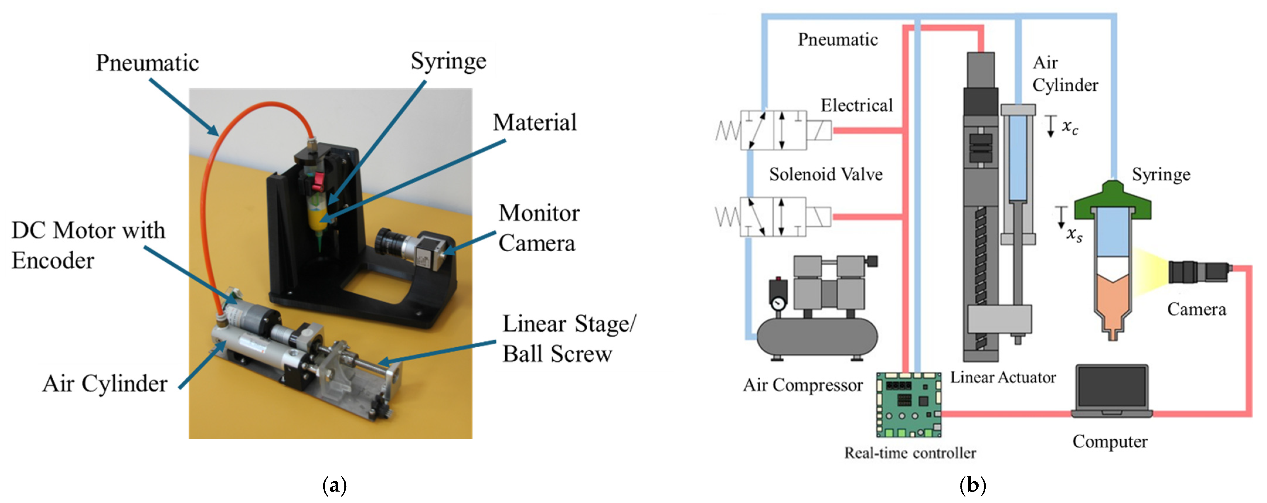
To address the limitations of these conventional approaches, an electro-pneumatic extrusion actuation system is proposed in this study as shown in Figure 2. The system comprises a DC motor-driven ball screw, which adjusts the displacement of a plunger within a pneumatic cylinder. This displacement modulates the internal pressure of a connected chamber, which in turn regulates the extrusion of material from the syringe.
Unlike traditional pneumatic systems, which rely solely on open-loop pressure supply, this architecture enables closed-loop displacement-based control for fine-tuning the extrusion pressure. The pneumatic source (air compressor) provides baseline pressurization, while the motorized screw dynamically regulates that pressure in real time. This hybrid electro-mechanical–pneumatic approach combines the advantages of pneumatic simplicity with the precision of mechanical actuation. Additionally, it enables internal state estimation via motor encoder feedback and optional pressure sensing, facilitating real-time volumetric flow control and future integration with intelligent controllers.
Pneumatic actuation was selected over hydraulic alternatives due to the specific requirements of bioprinting-related applications. Pneumatic systems operate with clean compressed air, avoid leakage of working fluids, and allow for a more compact and safer setup compared to hydraulic systems, which are bulkier and raise contamination concerns in laboratory environments.

2.2. The System Architecture of Electro-Pneumatic Extrusion Actuator

Figure 3 illustrates the system architecture of the electro-pneumatic extrusion actuator, which is designed to enable precise regulation of volumetric flow during extrusion-based additive manufacturing. The system integrates a pneumatic pressure reservoir with a mechanically actuated pressure tuning unit, offering both coarse and fine-grained pressure control for consistent material deposition through a syringe nozzle.
The pneumatic subsystem comprises an air compressor and a pressure tank (Festo (Esslingen, Germany) 750 mL, G1/4, CRVZS Series, rated at 16 bar) used to supply baseline pressure to the extrusion system. This pressure is initially regulated to a desired set point using an electro-pneumatic regulator (SMC ITV2030-322S (SMC Corporation (Tokyo, Japan))). However, standalone use of the tank and regulator does not provide sufficient precision for maintaining stable volumetric flow, particularly when material properties vary during the printing process.
To address this, a rodless pneumatic cylinder—magnetically coupled—is incorporated and connected to a ball screw linear stage with an effective stroke of 100 mm and shaft diameter of 16 mm. The position of the cylinder piston is controlled by the motion of the ball screw, which is driven by a Leadshine DCM57207D-1000 brushed DC servo motor (Leadshine (Shenzhen, China)). Motor actuation is handled by the Smile Robotics PRIK-THAI motor driver (Smile Robotics (Bangkok, Thailand)), and encoder feedback is used for closed-loop position tracking.
Two 3/2 solenoid valves are deployed to direct airflow: one to supply compressed air to the syringe, and another to release residual pressure, ensuring system safety and precise modulation. The combination of tank pressure and piston displacement enables both macro- and micro-scale tuning of extrusion force.
The entire system is powered by an AC77-02 unit (XP Power (Singapore)) that converts 220 VAC to 24 VDC. Control logic is executed via a BBBWL-SC-562 BeagleBone Black controller (GHI Electronics, LLC), which supports Simulink real-time execution through the MathWorks Embedded Coder interface. While a camera system is installed to monitor the plunger position of the syringe for experimental evaluation, it is not integrated into the control feedback loop.
This architecture enables precise, real-time control of material flow that incorporates simplified rheological dynamics, ensuring stability even when material viscosity or extrusion resistance varies dynamically.

2.3. Dynamic Modeling and Control Design

2.3.1. Dynamic Model of the System

The electro-mechanical actuation unit consists of a DC motor driving a ball screw linear stage, which in turn actuates a pneumatic cylinder connected to the extrusion pressure chamber. The dynamic behavior of this subsystem can be characterized using Newton’s second law for rotational motion and Kirchhoff’s voltage law for electrical circuits.
The electrical dynamics of the DC motor are governed by Kirchhoff’s voltage law and are described by:
L d i d t = R i K e θ ˙ + V
where L is the motor inductance, i is the armature current, R is the coil resistance, K e is the back electromotive force (EMF) constant, θ is the angular position of the motor shaft, V is the input voltage, and t is time.
The mechanical dynamics of the motor–ball screw system are described by:
J θ ¨ = K t i b θ ˙ F D ψ ( θ )
where J is the rotor’s moment of inertia, K t is the motor torque constant, b is the viscous friction coefficient, and F D represents the reaction force exerted by the pneumatic cylinder. The term ψ ( θ ) accounts for the nonlinear frictional torque in the transmission [28]. The parameter denotes the mechanical transmission gain of the ball screw and is given by:
= l 2 π η t h r e a d η t h r u s t
where l is the lead of the ball screw, and η t h r e a d and η t h r u s t are the mechanical efficiencies of the screw thread and thrust bearing, respectively [29].
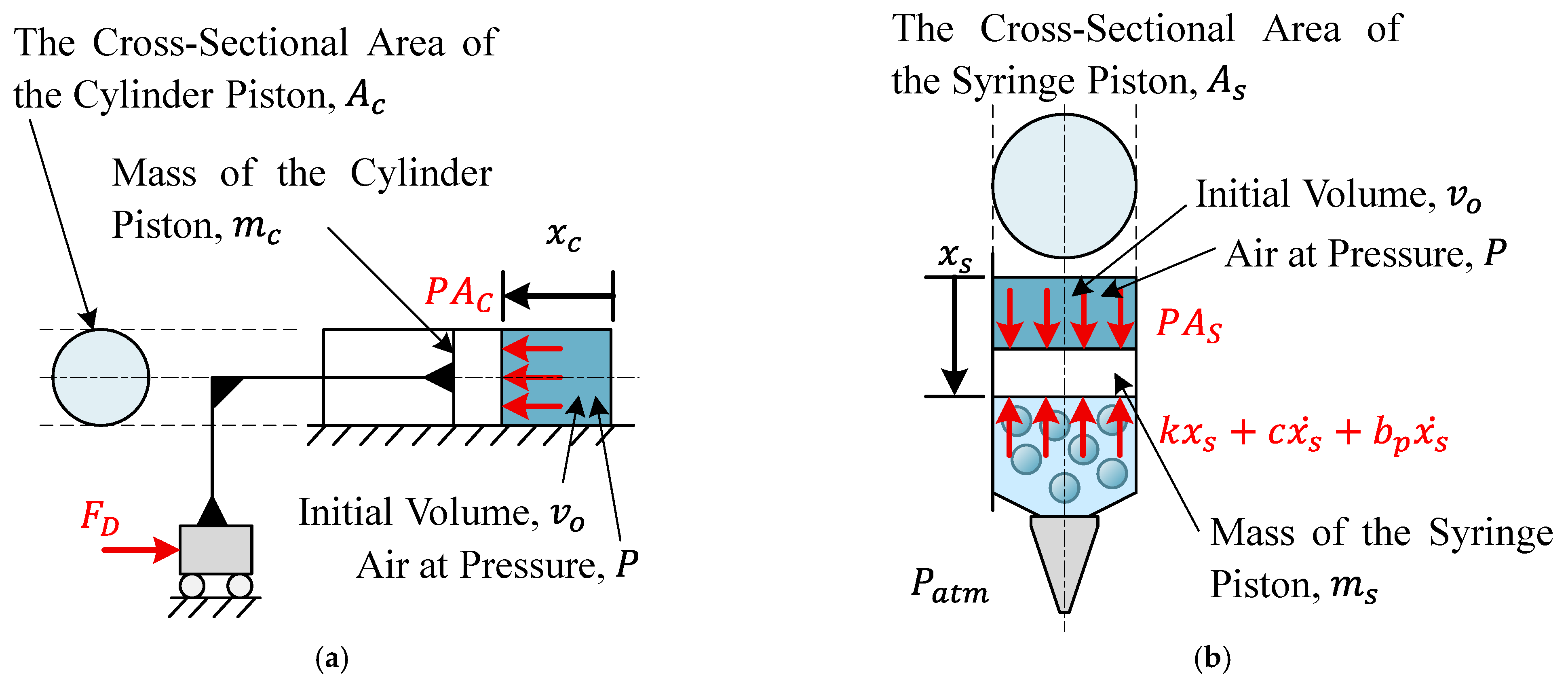
For the pneumatic cylinder, its mechanical dynamics are illustrated by the free-body diagram in Figure 4a. The cylinder piston is actuated by the force F D , which is the reaction force applied by the internal air pressure within the chamber. The piston dynamics can be described by Newton’s second law:
m c x ¨ = P A c F D
where m c is the mass of the cylinder piston, x is the linear position of the piston driven by the ball screw, A c is the cross-sectional area of the cylinder piston, and P is the internal chamber pressure.
The position x of the piston is directly related to the angular position of the motor shaft θ via the ball screw mechanism:
x c = l θ 2 π
where l is the lead or pitch of the ball screw.
The motion of the syringe piston, which compresses the viscoelastic material and drives it out through the nozzle, can be modeled using a Kelvin–Voigt viscoelastic system [21,22]. The free body diagram of the syringe piston is shown in Figure 4b, and the dynamic equation governing its behavior is given in Equation (6):
m s x ¨ s = P A s k x s c x ˙ s b p x ˙ s
where m s is the mass of the syringe piston, x s is the position of the syringe piston, A s is the cross-sectional area of the piston. The terms k and c represent the elastic and viscous coefficients of the extruded material, respectively, while b p is the piston friction coefficient.
The chamber that stores pressurized air is connected to both the pneumatic cylinder and the top inlet of the syringe. Hence, the total air volume in the chamber is affected by the displacements of both pistons. According to the isothermal form of Boyle’s law, the pressure dynamics in the chamber are given by [30,31]:
P =   P 0 v 0 v 0 A c x c + A s x s
where P 0 and v 0 are the initial pressure and volume of the chamber, respectively, and A s is the cross-sectional area of the syringe piston. The term A c x c accounts for the volume reduction due to the forward motion of the cylinder piston, while + A s x s accounts for the expansion from the downward motion of the syringe piston.
By substituting Equation (5) into Equation (4), and then integrating it into the dynamic model of the DC motor, the updated rotational dynamics become:
J m c l 2 π θ ¨ = K t i b θ ˙ A c P ψ ( θ )
where P is defined by Equation (6).
With Equations (1), (6) and (8), the state space model of the system is defined by
d i d t θ ¨ θ ˙ = R / L K e / L 0 K t / J e b / J e 0 0 1 0 i θ ˙ θ + 1 / L 0 0 V + 0 1 0 μ 1 + 0 ψ ( θ ) / J e 0 ,
μ 1 = A c J e P 0 v 0 v 0 A c l θ 2 π + A s x s
x ¨ s x ˙ s = ( c b p ) / m s k / m s 1 0 x ˙ s x s + 1 0 μ 2
μ 2 = A s m s P 0 v 0 v 0 A c l θ 2 π + A s x s
where J e = J m c l 2 π .
The angular position of the motor, θ , serves as the measurable output in this system, and the measurement equation is given by:
y = 0 0 1 i θ ˙ θ
Equations (9)–(13) summarize the system dynamics, with voltage V and initial pressure P 0 as inputs, and motor angular position θ as the observable output. The nonlinearity comes from friction and the pressure dynamics, which depend nonlinearly on the displacements x c and x s ; the latter is unmeasurable and uncontrollable directly, further complicating the control strategy.

2.3.2. Unknown Input Observer Design and Flow Control Strategy

In this system, accurate estimation of the internal states is essential for reliable volumetric flow control. While the angular position of the motor, θ , is directly measurable, other critical variables such as the plunger position of the syringe, x s , and its rate of change x ˙ s , cannot be measured directly. To address this, an unknown input observer (UIO) is designed to estimate the unmeasurable states.
The control architecture is illustrated in Figure 5. A PI controller is implemented using the estimated plunger velocity x ˙ s to regulate the flowrate. (Also, in the case that the user wants to control the plunger position x s , the estimated plunger position x s can be used to control the position.) The design of the observer enables estimation of the internal states, thus eliminating the need for a dedicated flow sensor.
This section presents a framework for observer design in nonlinear dynamic systems subject to unknown inputs.
x ˙ = A ¯ x + η x , u + B ¯ μ ,
y = C x
where x represents the state vector of the system, u R P denotes the known control inputs, μ R P are the unknown inputs, and y R q corresponds to the measured outputs. A ¯ R n × n , B ¯ R n × p , and C R q × n are system parameters of appropriate dimensions. The function η x , u : R n × R p R n is a differentiable nonlinear mapping with a globally (or locally) bounded Jacobian [32,33].
Following the unknown input estimation approach described in Ref. [32], the relative degree of the nonlinear extrusion system is defined. Theorem 1 from the same reference is applied to address single unknown input estimation. In the present system, this methodology enables the estimation of unmeasurable internal variables by reconstructing the unknown input to the dynamic model. The resulting estimated input is then used to infer the internal system states as follows:
μ ^ = C A ¯ r μ 1 B ¯ 1 y f r μ C A ¯ r μ x C A ¯ r μ 1 η x , u ,
where μ ^ denotes the estimated unknown input, r μ represents the relative degree from the unknown input μ to the output y , and y f is the derivative of the output signal. To reduce the effect of measurement noise, the output derivatives y f are filtered through a low-pass filter.
In practice, a cascade of first-order low-pass filters with time constant τ was employed to obtain smoothed derivatives. As τ decreases, the filtered derivatives converge to the true values, while a finite τ provides effective noise attenuation. The filter was discretized at the controller sampling rate using the bilinear (Tustin) transform and inserted upstream of the observer. The choice of τ balances the trade-off between noise reduction and delay: τ was selected to be small relative to the piston motion bandwidth but large enough to attenuate measurement noise. A similar filtering strategy for derivative estimation has been validated in prior observer design work [32].
Once the unknown input, μ , has been estimated, it can be replaced by its estimate μ ^ , in Equation (14). This substitution allows the system described by Equations (14) and (15) to be reformulated into a standard nonlinear observer-compatible form as follows:
x ˙ = A x + Φ x , u + g y f ,
y = C x
where A R n × n is an appropriate system matrix, and Φ x , u : R n × R p R n is a nonlinear function. Moreover, Φ x , u is assumed to be differentiable with a globally (or locally) bounded Jacobian.
With the system now expressed in the standard nonlinear form as shown in Equations (17) and (18), observer design can proceed following the methodologies outlined in Refs. [32,33]. A standard nonlinear observer is assumed to take the form
x ^ ˙ = A x ^ + Φ x ^ , u + g y f + L L y y ^ ,
y ^ = C x ^ .
where x ^ denotes the estimated system states, y ^ is the estimated measurement output, and L L represents the observer gain matrix, which can be determined using conventional nonlinear observer design techniques.
To implement this observer for the present system, the unknown input μ 1 in Equation (10) must first be estimated. Accordingly, Equations (9) and (13) are restructured to match the form of Equations (14) and (15).
A ¯ = R / L K e / L 0 K t / J e b / J e 0 0 1 0 , η x , u = 1 / L 0 0 V + 0 ψ ( θ ) / J e 0 , B ¯ = 0 1 0
C = 0 0 1
The unknown input μ 1 can then be estimated using Equation (16), leading to the expression in Equation (23):
μ ^ 1 = y ¨ f K t J e i ^ + b J e θ ˙ ^ ψ ( θ ^ ) J e
where y ¨ f represents the filtered second derivative of the measured output θ ¨ , obtained via a low-pass filter to mitigate noise.
Once μ 1 is estimated, the deformation or displacement of the syringe piston, x s can be algebraically calculated using Equation (10). Subsequently, the internal chamber volume of the syringe can be determined as v 0 A c l θ 2 π + A s x s and the input μ 2 of Equation (11) can be determined by Equation (12). With this information, the system can be reformulated into the structure of Equations (17) and (18), allowing for the application of a standard nonlinear observer design approach as described in Refs. [32,33].
The initial volumes of both the syringe and the pneumatic cylinder can be directly obtained from datasheets or physical measurements. As a result, no experimental procedures were required to determine pressure–volume characteristics. A summary of the key system parameters is provided in Table 1. All parameters listed in Table 1 were measured or taken directly from the experimental setup used in this manuscript.
To validate the performance of the unknown input observer, a simulation was implemented in MATLAB 2024b [34]. The simulation setup is illustrated in Figure 6, and the corresponding results are presented in Section 3. The example observer gain matrix, L L , used in the simulation and illustrated in Figure 6 is provided in Equation (24), while the PID gains are given in Equation (25).
L L = 298.5077 78.1703 19.5235 T
K p = 12000 ,   K I = 2000 ,   K d = 4000
Note: The PID controller gains were obtained using a two-step procedure. Initial values were selected following the Ziegler–Nichols closed-loop heuristic and then refined through constrained trial-and-error under the operating conditions of the extrusion system to achieve stable flow. The final gains used in this study are reported in Equation (25), consistent with the methodology in [28].

2.3.3. Control Technique

PID control was selected to regulate the volumetric flow rate of the syringe extrusion system. Since the syringe piston position, x s , is not directly measurable, its velocity x ˙ s —which corresponds to the material flow rate—was estimated using the unknown input observer developed in Section 2.3.2. The control architecture of the system is illustrated in Figure 7.
To enable real-time flow control, the PID controller was implemented in MATLAB Simulink, and the motor encoder signal was used as input for the observer. The estimated piston velocity ( x ˙ s ) was fed back to regulate extrusion flow. A unified Simulink model combining control logic, observer computation, and actuation commands was then deployed to the BeagleBone Black hardware using Embedded Coder. In this hardware-in-the-loop setup, the embedded system executes the control and sensing tasks at 1000 Hz, while the communication with the MATLAB host PC for monitoring and data logging operates at 25 Hz, consistent with MathWorks HIL methodology [34]. This separation ensures reliable real-time execution on the target hardware while maintaining efficient host–target interaction. The PID controller gains were tuned for stable and responsive flow regulation under these operating conditions.

3. Experimental Results and Discussions

3.1. Simulation Results of the Unknown Input Observer

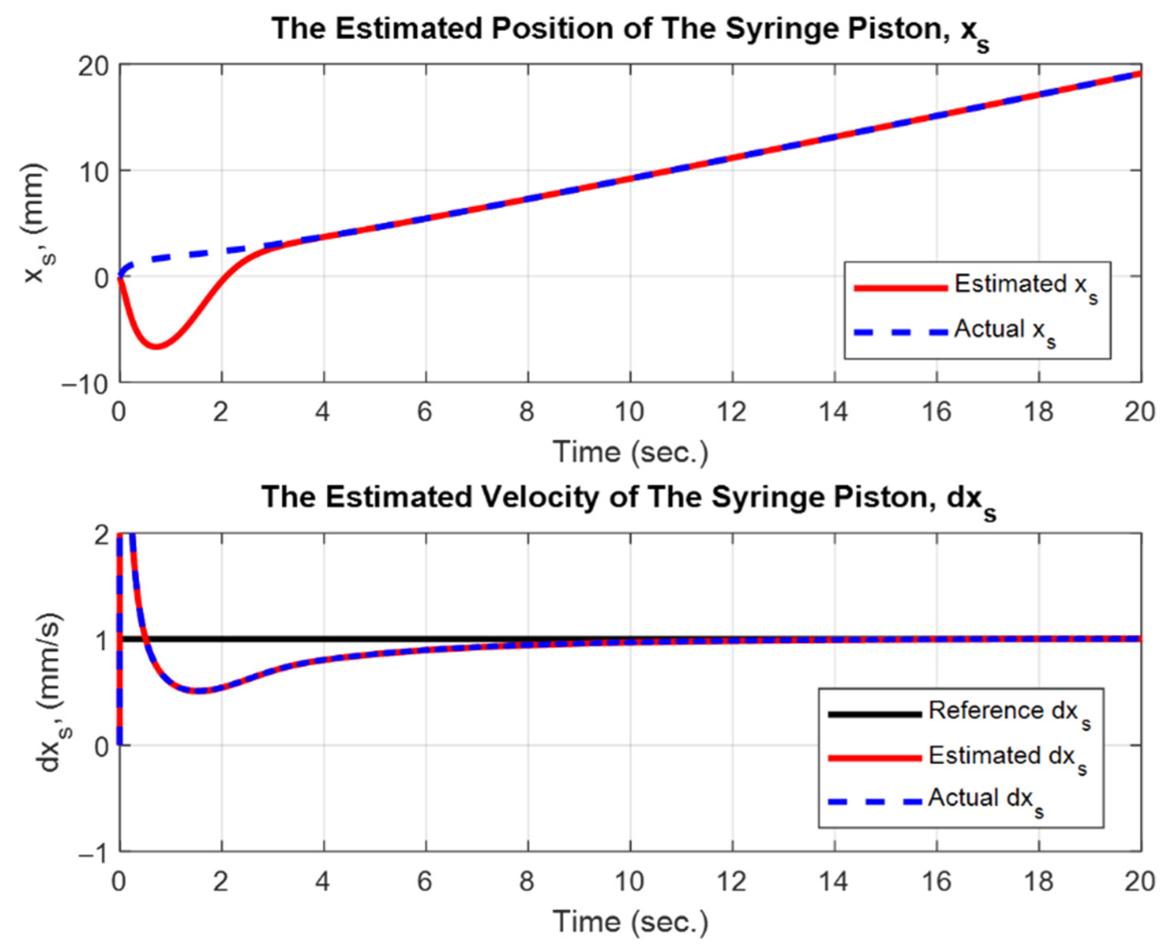
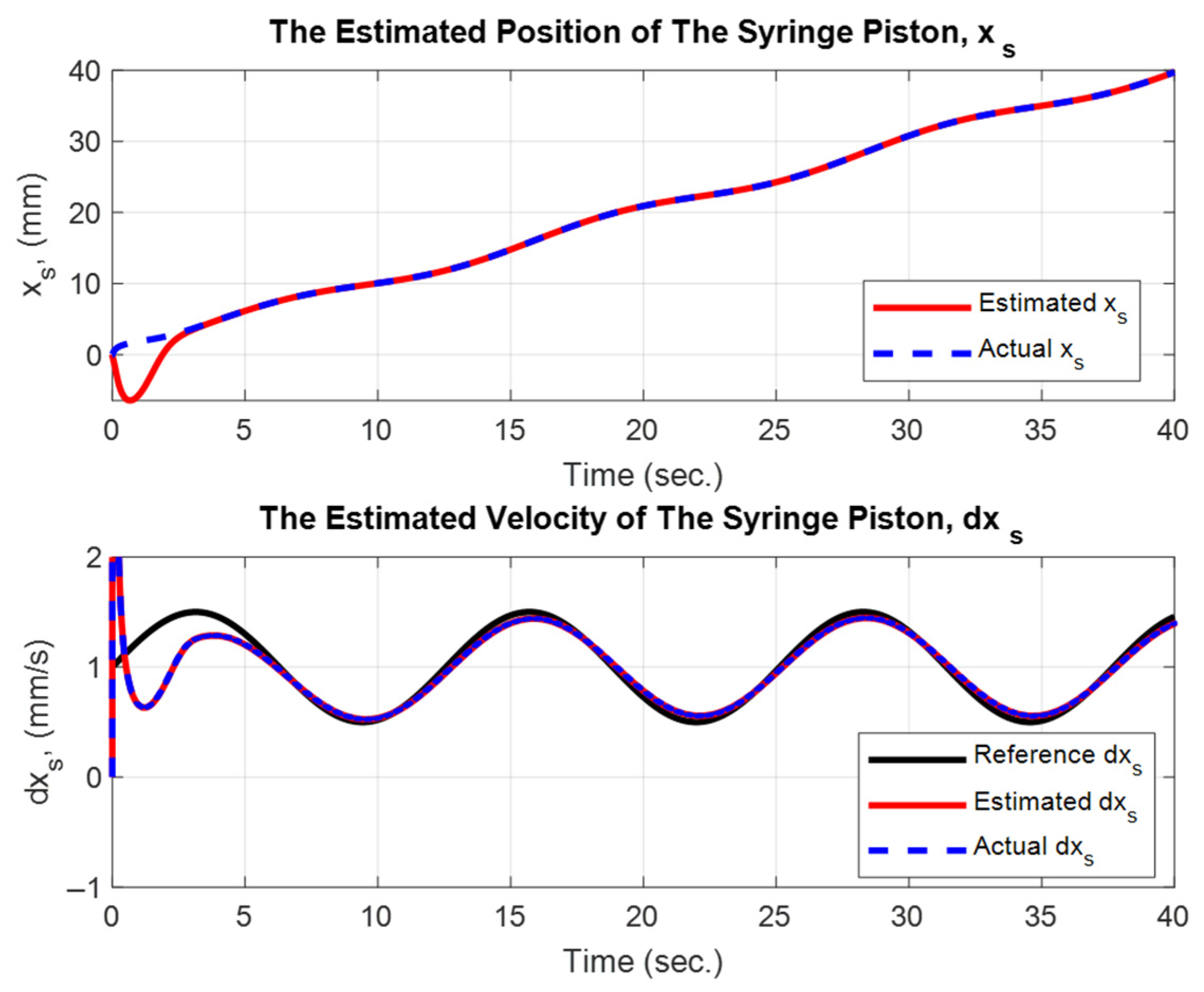
The simulation results demonstrate that the unknown input observer performs effectively. The observer can accurately estimate the syringe piston position x ^ s , as illustrated in Figure 8 and Figure 9. Figure 8 shows the case where the flow rate—represented by the velocity of the syringe piston x ˙ s —is controlled at a constant 1 mm/s. Figure 9 presents the case where the flow rate is controlled in a sinusoidal pattern, as indicated by the reference signal x ˙ s r e f . In both cases, a PID feedback control strategy was applied using the estimated syringe piston velocity x ^ ˙ s . The results confirm that the system is capable of tracking the desired flow rate reference with high accuracy.

3.2. Experimental Results of the System

To verify the effectiveness of the proposed control architecture integrating an Unknown Input Observer (UIO) and a feedback PID controller, a series of extrusion experiments were conducted using viscoelastic materials under varying actuation conditions. The primary objective was to assess whether the system could maintain a uniform flow rate and produce consistent printed linewidths ( w ), particularly under time-varying rheological properties during material deposition.
The system employs an electro-pneumatic actuator to drive a syringe plunger, where direct measurements of internal states—such as plunger velocity—are unavailable. The UIO is responsible for estimating the plunger velocity ( x ˙ s ), which is subsequently used in a closed-loop PID controller to regulate the extrusion rate. This feedback mechanism is designed to stabilize material flow despite actuator nonlinearities and variations in material viscosity.
The experimental setup utilized a two-component silicone resin, known to cure and increase in viscosity over time, thereby serving as a representative test case for evaluating robustness. A 30 mL syringe fitted with a 1.55 mm tapered nozzle was used. Throughout the experiment, the PID controller modulated the motor current (i) based on the estimated x ˙ s to compensate for changes in flow resistance.
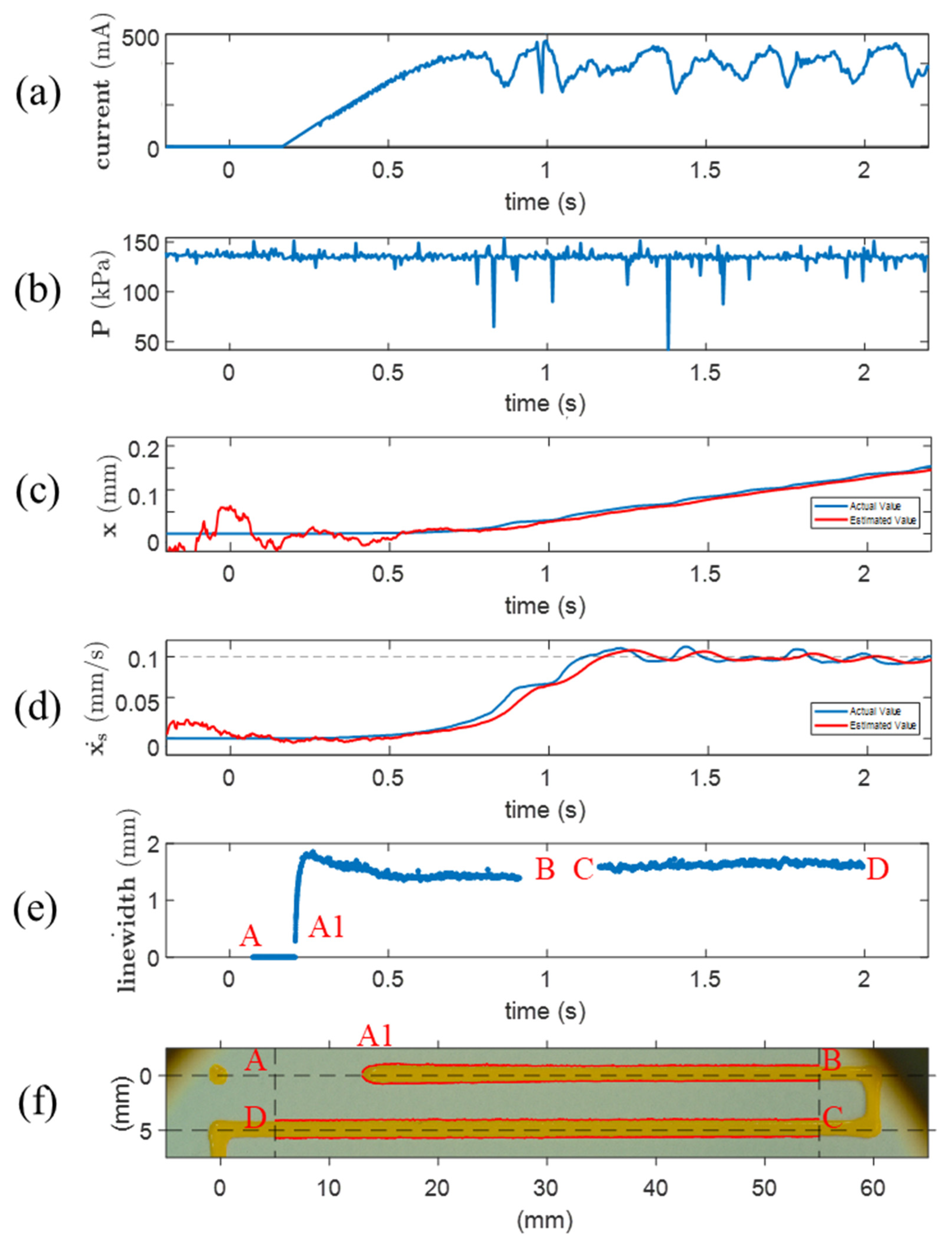
Figure 10 presents the experimental results obtained with the proposed control system. The subfigures illustrate: (a) motor current, (b) initial pressure of the air compressor, (c) syringe piston position monitored via a camera system, (d) syringe piston velocity derived from position data, and (e) the measured linewidth of the extruded material. The actual extruded line shown in Figure 10f was analyzed using image-based measurement tools, with position-to-time mapping for accurate evaluation.
The control system began operating at approximately 0.2 s. During this period, the motor adjusted the pneumatic cylinder position to increase system pressure, as reflected in the 0.2–0.8 s interval. The initial pressure was set at around 140 kPa. The syringe piston started moving at around 0.5 s, initiating material extrusion. However, due to underestimated friction and potential convergence delay of the observer, the extrusion was unstable during the first 0.5 s. The interval from 0.5 to 1.0 s can be characterized as the transient response phase, where pressure buildup and flow regulation were still stabilizing.
After 1.0 s, the system achieved steady-state behavior. The syringe piston moved with a nearly constant velocity of approximately 0.1 mm/s, as shown in Figure 10d. This resulted in a steady extrusion rate, as evidenced by the uniform piston displacement in Figure 10c and the stable linewidth observed in Figure 10e, particularly in the C–D interval.
Figure 10c,d compare the syringe piston position and velocity obtained from the camera measurements (blue line) with those estimated by the Unknown Input Observer (red line). The close agreement between the measured and estimated values confirms the accuracy of the observer in capturing the internal system states in real time. This validation demonstrates that the UIO provides reliable state information for closed-loop control, even in the absence of direct flow sensors.
Quantitative analysis of the extruded linewidth indicates that during the initial A1–B interval, the mean width was 1.4856 mm with a standard deviation (SD) of 0.1420 mm, reflecting unsteady flow. In contrast, during the steady-state C–D interval, the mean width slightly increased to 1.6224 mm, while the SD significantly decreased to 0.0388 mm. This low variation confirms that the material flow was highly stable once steady-state was reached.
These findings validate that the integration of UIO-based state estimation with PID feedback control significantly improves flow stability. The framework ensures consistent material deposition without requiring direct flow sensing, which is often infeasible in compact syringe-based extruders. Furthermore, it effectively compensates for nonlinear rheological behavior and transient disturbances, enabling precise control suitable for high-fidelity additive manufacturing.

3.3. Discussion

The experimental results validate the effectiveness of the proposed observer-based flow control architecture for extrusion-based additive manufacturing. By utilizing an Unknown Input Observer (UIO), the system successfully estimates the syringe plunger velocity, a critical internal state that is not directly measurable. This enables closed-loop regulation of material flow without the need for external flow sensors, making the approach especially attractive for compact, cost-sensitive extrusion systems.
Compared to traditional open-loop or feed-forward strategies that rely on static material assumptions, the UIO–PID framework exhibits greater adaptability to dynamic changes in rheological properties, such as viscosity increases during material curing. The control system demonstrates the ability to maintain stable extrusion flow, as evidenced by the narrow linewidth variation during steady-state operation. The smooth transition from transient to steady-state behavior further highlights the controller’s ability to compensate for nonlinearities and delays inherent in electro-pneumatic actuation systems.
A major strength of the proposed system lies in its hybrid actuation design, which combines pneumatic preloading for coarse pressure generation with a motorized ball screw mechanism for fine-tuned adjustments. This dual-mode approach allows for rapid pressure compensation with minimal motor effort, contributing to the system’s efficiency and responsiveness. Moreover, the integration of rheological dynamics into the nonlinear state-space model provides insight into internal system behavior and lays the groundwork for future extensions involving thermal effects, multi-phase materials, or phase transitions.
While this study focused on a single viscoelastic material using a syringe-based extrusion setup, the modular control framework and general observer design suggest that the system can be extended to other actuation platforms and a broader range of materials. Applications such as bioprinting, electronics printing, and soft robotics, which demand precise flow control under variable conditions, could particularly benefit from this approach.
In summary, the combination of nonlinear modeling, observer-based state estimation, and closed-loop PI control yields a robust and adaptive flow regulation system. The architecture effectively suppresses flow instability and compensates for rheological variation, positioning it as a promising solution for next-generation extrusion-based manufacturing platforms that require precision, flexibility, and autonomy.
Nevertheless, this study has several limitations that should be acknowledged. On the modeling side, the framework employs a simplified Kelvin–Voigt viscoelastic model with constant coefficients [21,22]. While this baseline representation enables tractable real-time integration, it does not capture nonlinear rheological behaviors such as shear-thinning and yield stress. Thus, the present contribution is positioned as a first step toward rheology-integrated flow regulation, with future work directed at incorporating more advanced models. On the experimental side, validation was limited to a single viscoelastic material—a curing silicone resin—selected for its widespread use and challenging rheological profile. The toolpath considered was restricted to a straight trajectory under near-constant velocity conditions, and comparative tests against conventional controllers were not conducted. While these settings provided a controlled environment to demonstrate feasibility, broader evaluations with multiple materials, complex trajectories, and side-by-side benchmarks remain important future directions, especially in bioprinting and soft robotics applications.

4. Conclusions

This study presents a model-based volumetric flow control system for extrusion-based additive manufacturing that integrates nonlinear dynamic modeling, an unknown input observer (UIO), and a closed-loop PID controller. The system addresses challenges posed by unmeasurable internal states and rheological variability in viscoelastic materials, enabling real-time and stable flow regulation without the need for direct flow sensors.
Simulation results confirm the accuracy of the proposed UIO in estimating syringe plunger velocity, which is then used as a feedback variable for flow control. Experimental results further demonstrate that the system can maintain consistent material deposition—even under changing material resistance due to curing—achieving stable printed linewidth with minimal variation and fast response times.
The hybrid actuation design, which combines pneumatic preloading with motorized pressure adjustment, allows for effective compensation of nonlinear and time-varying behaviors in the extrusion process. The proposed architecture is modular, adaptable, and suitable for various extrusion applications, particularly those requiring precision and responsiveness, such as in bioprinting, soft robotics, and functional composite fabrication.
Future work will explore the integration of real-time rheological sensing, digital twin-based predictive control, and extension to multi-material or multilayer extrusion scenarios to further enhance system intelligence and autonomy.

Author Contributions

Conceptualization, C.S., S.S. and R.C.; Data curation, K.C. and R.C.; Formal analysis, C.S., K.C. and G.P.; Funding acquisition, G.P.; Investigation, C.S. and K.C.; Methodology, C.S., K.C., S.S. and G.P.; Project administration, G.P.; Resources, R.C. and G.P.; Software, C.S. and K.C.; Supervision, S.S., R.C. and G.P.; Validation, C.S. and K.C.; Visualization, R.C. and G.P.; Writing—original draft, C.S., K.C., R.C. and G.P.; Writing—review and editing, C.S., K.C., S.S., R.C. and G.P. All authors have read and agreed to the published version of the manuscript.

Funding

This research project is supported by the Second Century Fund (C2F) and the Thailand Science Research and Innovation Fund (IND_FF_68_209_2100_031 and IND_FF_68_007_2100_001), Chulalongkorn University; and by the 111th Anniversary Engineering Research Empowerment Grant: Advancing Towards a World Top 100 University (111th Anniversary Grant) – Project: Design and Development of a Robotic Spray Painting System with Digital Twin Integration, Chulalongkorn University.

Data Availability Statement

Any inquiry can be directly sent to the corresponding author.

Acknowledgments

We would like to thank the Immersive Technology Laboratory (IMT Lab), Faculty of Engineering, Chulalongkorn University, for their support. During the preparation of this manuscript, the authors used ChatGPT (GPT-5, OpenAI, 2025) to assist in language editing and refinement of the text. The authors have reviewed and edited the output and take full responsibility for the content of this publication.

Conflicts of Interest

The authors declare no conflicts of interest.

References

  1. Bakrani Balani, S.; Mokhtarian, H.; Salmi, T.; Coatanéa, E. An investigation of the influence of viscosity and printing parameters on the extrudate geometry in the material extrusion process. Polymers 2023, 15, 2202. [Google Scholar] [CrossRef]
  2. Schuller, T.; Jalaal, M.; Fanzio, P.; Galindo-Rosales, F.J. Optimal shape design of printing nozzles for extrusion-based additive manufacturing. Addit. Manuf. 2024, 84, 104130. [Google Scholar] [CrossRef]
  3. Jang, J.W.; Min, K.E.; Kim, C.; Wern, C.; Yi, S. Rheological properties and 3D printing behavior of PCL and DMSO2 composites for bio-scaffold. Materials 2024, 17, 2459. [Google Scholar] [CrossRef]
  4. del-Mazo-Barbara, L.; Ginebra, M.P. Rheological characterisation of ceramic inks for 3D direct ink writing: A review. J. Eur. Ceram. Soc. 2021, 41, 18–33. [Google Scholar] [CrossRef]
  5. Gharraei, R.; Bergstrom, D.; Chen, X.D. Extrusion bioprinting from a fluid mechanics perspective. Int. J. Bioprint. 2024, 10, 3973. [Google Scholar] [CrossRef]
  6. Guidetti, X.; Mingard, N.; Cruz-Oliver, R.; Nagel, Y.; Rueppel, M.; Rupenyan, A.; Balta, E.C.; Lygeros, J. Force controlled printing for material extrusion additive manufacturing. Addit. Manuf. 2024, 89, 104297. [Google Scholar] [CrossRef]
  7. Marnot, A.; Koube, K.; Jang, S.; Thadhani, N.; Kacher, J.; Brettmann, B. Material extrusion additive manufacturing of high particle loaded suspensions: A review of materials, processes and challenges. Virtual Phys. Prototyp. 2023, 18, e2279149. [Google Scholar] [CrossRef]
  8. Cooke, M.E.; Rosenzweig, D.H. The rheology of direct and suspended extrusion bioprinting. APL Bioeng. 2021, 5, 011502. [Google Scholar] [CrossRef] [PubMed]
  9. Lukhi, M.; Mittermeier, C.; Kiendl, J. Multi-physics simulation of a material extrusion-based additive manufacturing process: Towards understanding stress formation in the printed strand. Prog. Addit. Manuf. 2025, 10, 6839–6853. [Google Scholar] [CrossRef]
  10. Bernagozzi, G.; Battegazzore, D.; Arrigo, R.; Frache, A. Optimizing the rheological and thermal behavior of polypropylene-based composites for material extrusion additive manufacturing processes. Polymers 2023, 15, 2263. [Google Scholar] [CrossRef]
  11. Khan, I.; Barsoum, I.; Abas, M.; Al Rashid, A.; Koç, M.; Tariq, M. A review of extrusion-based additive manufacturing of multi-materials-based polymeric laminated structures. Compos. Struct. 2024, 349–350, 118490. [Google Scholar] [CrossRef]
  12. Altıparmak, S.C.; Yardley, V.A.; Shi, Z.; Lin, J. Extrusion-based additive manufacturing technologies: State of the art and future perspectives. J. Manuf. Process. 2022, 83, 607–636. [Google Scholar] [CrossRef]
  13. Moretti, M.; Rossi, A.; Senin, N. In-process simulation of the extrusion to support optimisation and real-time monitoring in fused filament fabrication. Addit. Manuf. 2021, 38, 101817. [Google Scholar] [CrossRef]
  14. McAfee, M.; Kariminejad, M.; Weinert, A.; Huq, S.; Stigter, J.D.; Tormey, D. State estimators in soft sensing and sensor fusion for sustainable manufacturing. Sustainability 2022, 14, 3635. [Google Scholar] [CrossRef]
  15. Youssef, S.M.; Soliman, M.; Saleh, M.A.; Mousa, M.A.; Elsamanty, M.; Radwan, A.G. Modeling of soft pneumatic actuators with different orientation angles using echo state networks for irregular time series data. Micromachines 2022, 13, 216. [Google Scholar] [CrossRef]
  16. Brown, D.F.; Xie, S.Q. Model Predictive Control with Optimal Modelling for Pneumatic Artificial Muscle in Rehabilitation Robotics: Confirmation of Validity Though Preliminary Testing. Biomimetics 2025, 10, 208. [Google Scholar] [CrossRef]
  17. Cao, G.; Liu, Y.; Zhu, Z. Observer-based adaptive robust control of soft pneumatic network actuators. Int. J. Control Autom. Syst. 2022, 20, 1695–1705. [Google Scholar] [CrossRef]
  18. Oleff, A.; Küster, B.; Stonis, M.; Overmeyer, L. Process monitoring for material extrusion additive manufacturing: A state-of-the-art review. Prog. Addit. Manuf. 2021, 6, 705–730. [Google Scholar] [CrossRef]
  19. Liu, Y.-C. Disturbance-Observer-Based Sliding-Mode Speed Control for Synchronous Reluctance Motor Drives via Generalized Super-Twisting Algorithm. Actuators 2024, 13, 233. [Google Scholar] [CrossRef]
  20. Jiang, C.; Yang, Z.; Zheng, J.; Fu, B.; Bai, Y. Research on Active Disturbance Rejection Control of Rigid–Flexible Coupled Constant Force Actuator. Actuators 2025, 14, 325. [Google Scholar] [CrossRef]
  21. Chaiprabha, K.; Sithiwichankit, C.; Chungsangsatiporn, W.; Phanomchoeng, G.; Chancharoen, R. Digital Twin-Enabled Extrusion Control for High-Fidelity Printing of Polymers. Polymers 2025, 17, 2215. [Google Scholar] [CrossRef] [PubMed]
  22. Epaarachchi, J.A. The effect of viscoelasticity on fatigue behaviour of polymer matrix composites. In Creep and Fatigue in Polymer Matrix Composites; Woodhead Publishing: Cambridge, UK, 2010; pp. 492–513. [Google Scholar]
  23. Justino Netto, J.M.; Idogava, H.T.; Frezzatto Santos, L.E.; Silveira, Z.C.; Romio, P.; Alves, J.L. Screw-assisted 3D printing with granulated materials: A systematic review. Int. J. Adv. Manuf. Technol. 2021, 115, 2711–2727. [Google Scholar] [CrossRef]
  24. Estelle, K.T.; Gozen, B.A. Precision flow rate control during micro-scale material extrusion by iterative learning of pressure-flow rate relationships. Addit. Manuf. 2024, 82, 104031. [Google Scholar] [CrossRef]
  25. Fanucci, S.; Prinsloo, E. Development of a low-cost hydrogel microextrusion printer based on a Kossel delta 3D printer platform. Eng. Rep. 2023, 5, e12615. [Google Scholar] [CrossRef]
  26. Miri, A.K.; Nieto, D.; Iglesias, L.; Goodarzi Hosseinabadi, H.; Maharjan, S.; Ruiz-Esparza, G.U.; Khoshakhlagh, P.; Manbachi, A.; Dokmeci, M.R.; Chen, S.; et al. Microfluidics-Enabled Multimaterial Maskless Stereolithographic Bioprinting. Adv. Mater. 2018, 30, e1800242. [Google Scholar] [CrossRef]
  27. Malik, S.; Hagopian, J.; Mohite, S.; Lintong, C.; Stoffels, L.; Giannakopoulos, S.; Beckett, R.; Leung, C.; Ruiz, J.; Cruz, M.; et al. Robotic Extrusion of Algae-Laden Hydrogels for Large-Scale Applications. Glob. Chall. 2020, 4, 1900064. [Google Scholar] [CrossRef]
  28. Phanomchoeng, G.; Chancharoen, R. Hybrid motor system for high precision position control of a heavy load plant. Eng. J. 2019, 23, 161–173. [Google Scholar] [CrossRef]
  29. Jintanawan, T.; Phanomchoeng, G.; Suwankawin, S.; Kreepoke, P.; Chetchatree, P.; U-viengchai, C. Design of Kinetic-Energy Harvesting Floors. Energies 2020, 13, 5419. [Google Scholar] [CrossRef]
  30. Łukaszewicz, G.; Kalita, P. Navier–Stokes Equations: An Introduction with Applications; Springer: Cham, Switzerland, 2016. [Google Scholar]
  31. Strogatz, S.H. Nonlinear Dynamics and Chaos: With Applications to Physics, Biology, Chemistry, and Engineering; CRC Press: Boca Raton, FL, USA, 2018. [Google Scholar]
  32. Phanomchoeng, G.; Rajamani, R. Real-Time Estimation of Rollover Index for Tripped Rollovers with a Novel Unknown Input Nonlinear Observer. IEEE/ASME Trans. Mechatron. 2014, 19, 743–754. [Google Scholar] [CrossRef]
  33. Phanomchoeng, G.; Zemouche, A.; Jeon, W.; Rajamani, R.; Mazenc, F. H Observer for Descriptor Nonlinear Systems with Nonlinear Output Equations. In Proceedings of the 2018 Annual American Control Conference (ACC), Milwaukee, WI, USA, 27–29 June 2018; pp. 5952–5956. [Google Scholar] [CrossRef]
  34. The MathWorks Inc. Matlab. Available online: https://www.mathworks.com (accessed on 23 June 2024).
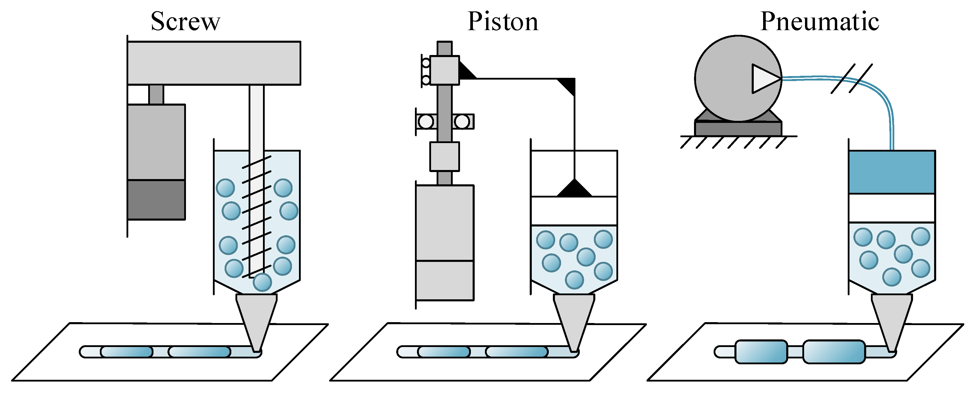
Figure 1. Deposition Mechanisms: Screw-based Actuators, Piston, and Pneumatic.
Actuators 14 00496 g001
Figure 2. Electro-Pneumatic Extrusion Actuator.
Actuators 14 00496 g002
Figure 3. System Architecture of Electro-Pneumatic Extrusion Actuator: (a) Photo of the system; (b) System diagram.
Actuators 14 00496 g003
Figure 4. The free body diagram of the components: (a) free body diagram of the pneumatic cylinder; (b) free body diagram of the syringe piston.
Actuators 14 00496 g004
Figure 5. The control architecture of the system.
Actuators 14 00496 g005
Figure 6. The unknown input observer simulation on Matlab/Simulink.
Actuators 14 00496 g006
Figure 7. Control Architecture.
Actuators 14 00496 g007
Figure 8. Estimated Syringe Piston Velocity Tracking under Constant Reference using Unknown Input Observer and PID Control.
Actuators 14 00496 g008
Figure 9. Estimated Syringe Piston Velocity Tracking under Sinusoidal Reference using Unknown Input Observer and PID Control.
Actuators 14 00496 g009
Figure 10. Extrusion results under observer-based PID control: (a) Motor Current, (b) Pressure of the air compressor, (c) Syringe Piston Position, (d) Syringe Piston Velocity, (e) Material Line Width, and (f) Photo of Material Line.
Actuators 14 00496 g010
Table 1. System parameters obtained from the experimental prototype developed in this study. All parameters listed in this table were measured or taken directly from the experimental setup used in this manuscript.
ComponentsParametersValueUnit
Pneumatic CylinderInitial Volume, v 0 25.5 m L
Cross-Section Area of the Piston, A c 201 m m 2
Mass of the Piston, m c 0.736 k g
Stroke Length153 m m
SyringeCross-Section Area of the Syringe, A s 397.25 m m 2
Mass of the Syringe, m s 0.1kg
DC MotorMoment of Inertia of the Rotor, J 4.73 × 10 5 k g · m 2
Electric Resistance, R 0.9 o h m
Electric Inductance, L 3.6 × 10 3 H
Electromotive Force Constant, K e 80 × 10 3 N · m / A
Motor Torque Constant, K t 80 × 10 3 N · m / A
Linear StagePitch of the Ball Screw, l 2 m m
Efficiencies of the Thread of Ball Screw, η t h r e a d 0.9
Efficiencies of the Thrust Bearing of Ball Screw, η t h r u s t 0.9
EncoderPulse per Revolution4000 p p r
1 Pulse of Encoder 0.006375 m m
The SystemAtmospheric Pressure101.325kPa
Initial temperature300K
Note: The observer gain matrix, L L , is shown in Equation (24) and the PID gain is shown in Equation (25).
Disclaimer/Publisher’s Note: The statements, opinions and data contained in all publications are solely those of the individual author(s) and contributor(s) and not of MDPI and/or the editor(s). MDPI and/or the editor(s) disclaim responsibility for any injury to people or property resulting from any ideas, methods, instructions or products referred to in the content.