1. Introduction
With the recent expansion of the eco-friendly vehicle market and vehicle electrification, the demand for Permanent Magnet Synchronous Motors (PMSMs) has increased significantly. The electric motor market, valued at approximately USD 18.2 billion in 2022, is projected to reach USD 32.2 billion by 2030, with demand for small motors also expected to continue rising [
1]. Consequently, research on steering systems is actively advancing, and the adoption of Electric Power Steering (EPS) is expanding, particularly to enhance driver handling and vehicle fuel efficiency [
2]. Among the core components of EPS is the PMSM, and the Interior Permanent Magnet Synchronous Motor (IPMSM), in which permanent magnets are embedded inside the rotor, has the advantage of utilizing both magnetic torque and reluctance torque due to rotor saliency.
However, the main material of PMSMs, rare-earth magnets, faces critical limitations such as price increases caused by supply instability and the environmental impact of mining [
3,
4,
5,
6,
7]. Therefore, designing PMSMs that reduce dependence on rare-earth usage is essential, and research is actively being conducted on employing alternative resources or minimizing rare-earth magnet content. A representative approach is the PMSM with a Consequent Pole (CP) structure [
8,
9,
10,
11,
12].
The CP structure can reduce magnet usage by up to 50% by replacing one pole with iron. In this case, since magnetic flux tends to flow preferentially through the iron path, which exhibits relatively lower magnetic reluctance, Lq increases significantly [
13]. As a result, in an IPMSM with a CP structure, the difference between Lq and Ld becomes larger than in a conventional IPMSM, thereby enhancing the reluctance torque component [
14]. Thus, applying the CP structure provides the advantage of greater utilization of reluctance torque. Nevertheless, replacing one pole with iron may induce magnetic imbalance, leading to asymmetric noload back-electromotive force (EMF), as well as increased cogging torque and torque ripple [
15,
16]. To mitigate these issues, prior studies have reported the use of asymmetric pole shapes or novel rotor geometries [
17,
18]. In EPS motors in particular, vibration is a major concern; accordingly, vibration-mitigation design is crucial to improving steering feel.
Therefore, this study introduces a new rotor structure to overcome the drawbacks of the CP-applied IPMSM, aiming to mitigate back-EMF asymmetry and enhance reluctance torque. The Intersect Consequent Pole (ICP) proposed in this paper is designed to induce a vertically symmetric flux distribution by arranging an N-pole CP structure (N-CP), using N-pole magnets over half of the stack length, and an S-pole CP structure (S-CP), using S-pole magnets over the remaining half, in an intersecting configuration. This symmetric flux distribution reduces back-EMF asymmetry compared with a conventional CP-IPMSM and also contributes to lowering cogging torque and torque ripple [
13,
19]. Consequently, the Intersect Consequent Pole Interior Permanent Magnet Synchronous Motor (ICP-IPMSM) achieves both reduced magnet usage and low-vibration characteristics simultaneously [
20].
However, in the ICP-IPMSM, axial leakage flux occurs at the interface between the N-CP and S-CP, leading to performance degradation. To address this issue, a rotor gap was introduced between the N-CP and S-CP to block leakage flux. Furthermore, to secure performance equivalent to that of the conventional model, more than 50% magnet usage is required, necessitating magnet optimization. Accordingly, in this study, the magnet was reselected through size redesign, and the irreversible demagnetization risk of the selected magnet was evaluated to ensure reliability [
21].
In conclusion, the proposed ICP-IPMSM reduces magnet usage while meeting target performance and maintaining low-vibration characteristics, and its validity is verified through Finite Element Analysis (FEA).
2. Analysis of Conventional Model
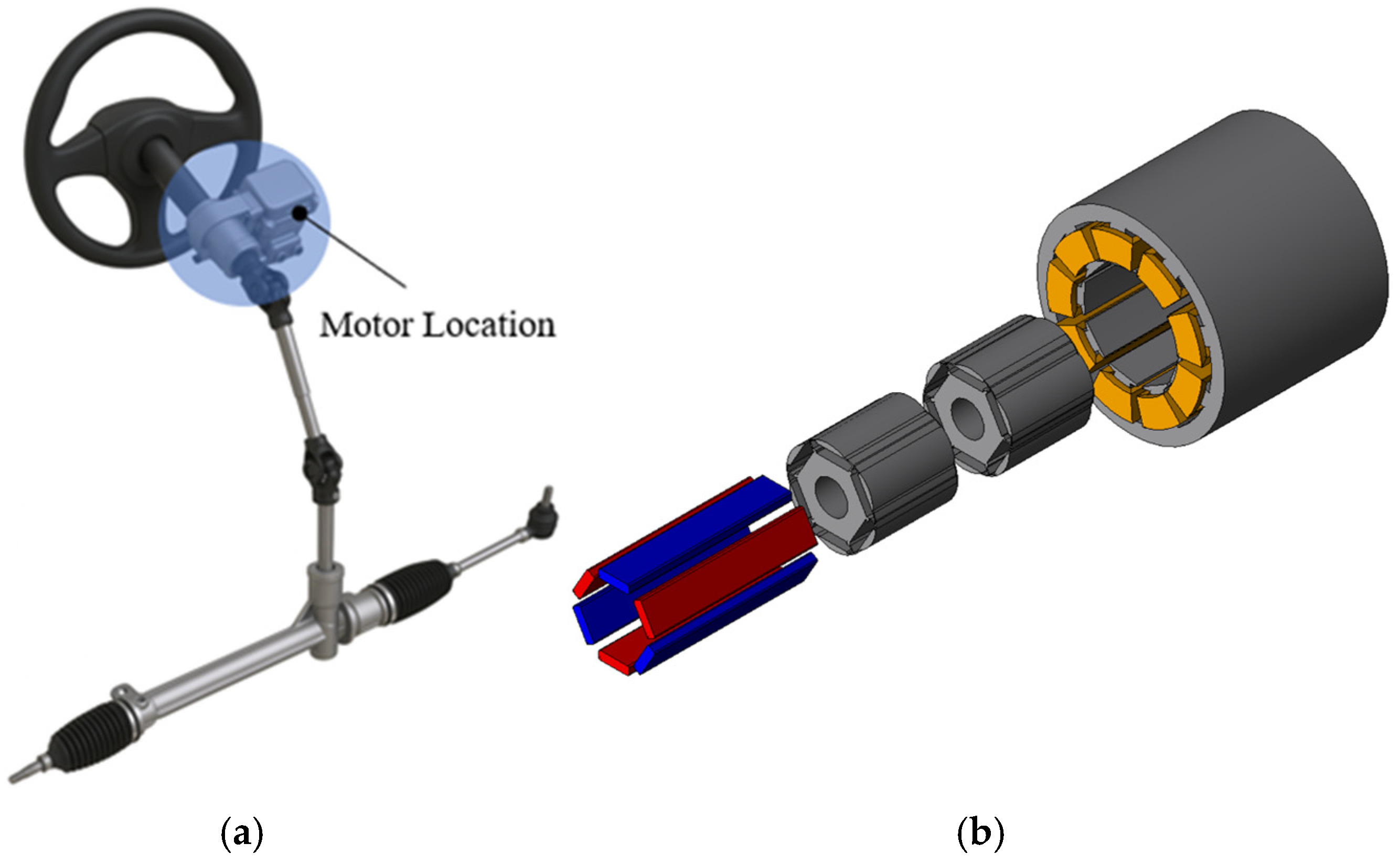
Figure 1a shows the structure of the EPS system, where the conventional motor is an IPMSM, advantageous for achieving high power density under the size constraints of vehicle structures.
Figure 1b presents the fabricated model of the conventional motor, and the specifications and target performance of the EPS motor are summarized in
Table 1. A double-layer concentrated winding was applied, and since EPS motors require compact size and high power, Maximum Torque per Ampere (MTPA) control was employed. In addition, to reduce vibration and noise, cogging torque was mitigated by applying a two-step skew and tapering to the rotor core.
Figure 2a shows the fabricated rotor of the conventional motor, and
Figure 2b illustrates the test environment. To verify the performance of the conventional motor, the line-to-line EMF was measured at 1000 rpm.
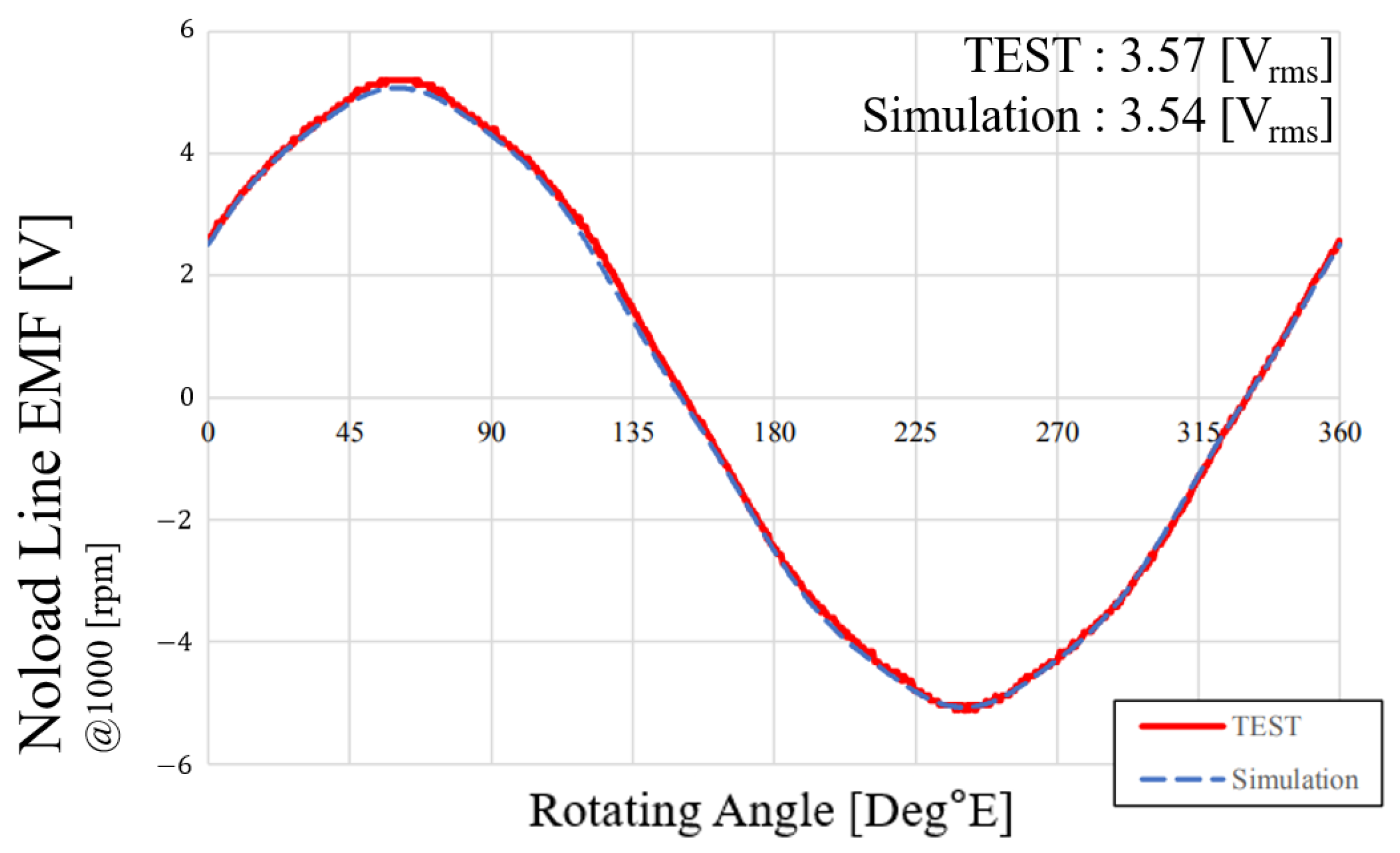
Figure 3 shows the no-load line-to-line EMF of phases U and V from both simulation and experimental data, where the error between simulation and experiment was approximately 0.84%, demonstrating strong consistency and validating the electromagnetic design of the conventional motor.
In the conventional motor, torque ripple and cogging torque were reduced through mechanical approaches such as two-step skew and tapering of the rotor core; however, introducing rotor skew increases the effective flux path length, thereby raising magnetic reluctance and reducing flux linkage, which leads to performance degradation. Therefore, in this study, rotor tapering and skew were removed from the conventional motor, and a CP structure was introduced to reduce magnet usage while maintaining the target performance with lower cogging torque and torque ripple.
3. Consequent Pole IPMSM Structure and Characteristics
In this study, a CP structure is applied to the IPMSM.
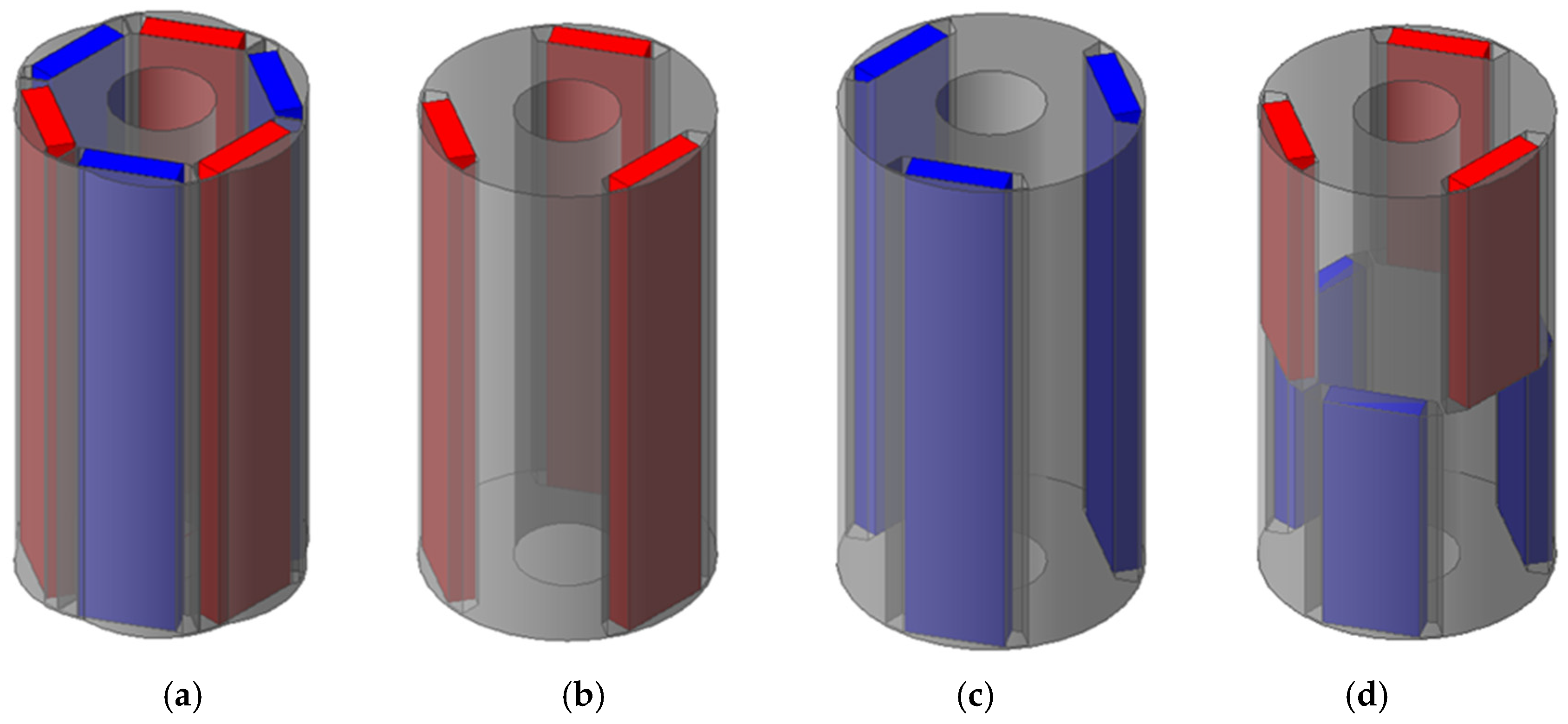
Figure 4 shows the rotor structures of the bar-type IPMSM.
Figure 4a illustrates the general bar type, in which the magnets form pairs of N- and S-poles.
Figure 4b,c present CP-IPMSMs, where one pole is replaced with iron instead of a magnet, unlike the conventional IPMSM.
Figure 4d shows the ICP-IPMSM, a new rotor structure introduced to overcome the drawbacks of the CP-IPMSM, which will be explained later. The ICP rotor intersects an N-CP structure, which uses N-pole magnets for half of the stack length, with an S-CP structure, which uses S-pole magnets for the other half of the stack length.
In the CP models shown in
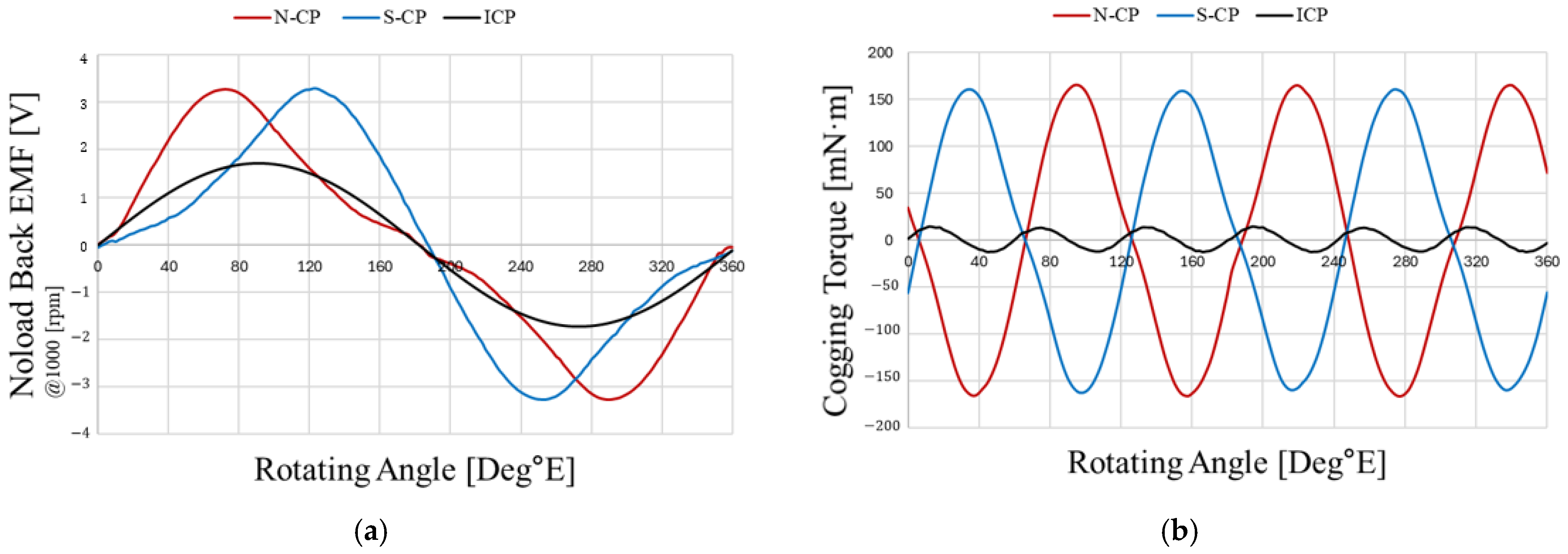
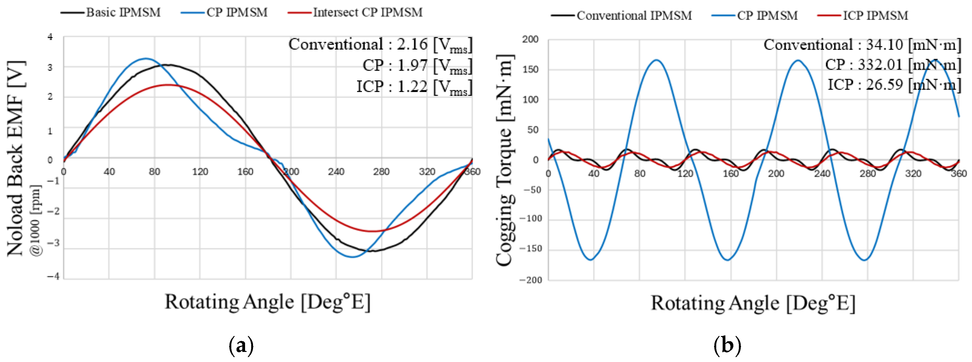
Figure 4b,c, one pole magnet is replaced with iron, resulting in magnetic imbalance due to the absence of magnetic reluctance. These structural characteristics lead to magnetic imbalance, which directly affects performance by causing back-EMF asymmetry, large torque ripple, high cogging torque, and reduced efficiency, and therefore require improvement. The back-EMF asymmetry and increased cogging torque caused by this magnetic imbalance are confirmed in
Figure 5.
In
Figure 5, the noload back-EMF waveforms of the N-CP and S-CP exhibit 180° phase symmetry, and the ICP, which arranges the two waveforms alternately for half of the stack length each, shows a back-EMF waveform closer to a sinusoidal shape. This occurs because fluxes of opposite polarity are symmetrically distributed in the upper and lower halves of the stack, significantly reducing waveform distortion.
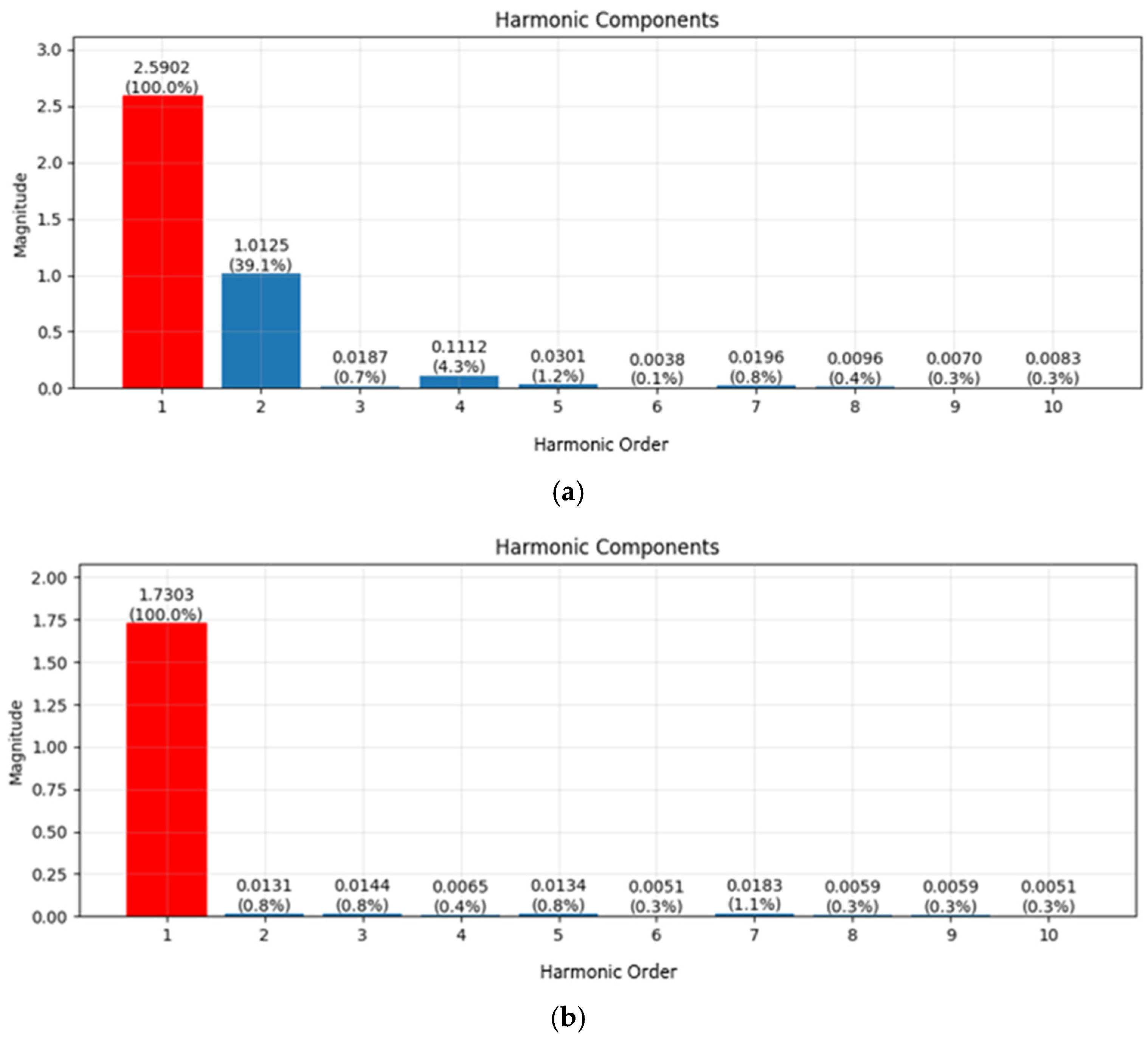
This result is also confirmed through Fast Fourier Transform (FFT) analysis. As shown in
Figure 6, in the case of the ICP, the even-order components are canceled, resulting in reduced even-order harmonics. For the same reason, cogging torque is also considerably reduced. However, averaging the two waveforms of the N-CP and S-CP does not preserve the same magnitude of the fundamental component, as the maximum amplitude decreases. This reduction is caused by the alleviation of flux concentration that occurs in a single CP and the axial leakage flux generated when the N-CP and S-CP are in axial contact.
As shown in
Figure 5b, the cogging torques of the N-CP and S-CP occur symmetrically with a 180° phase difference, and in the ICP, they are mutually canceled, thereby greatly reducing the overall cogging torque. In other words, compared with the CP, the ICP simultaneously achieves sinusoidal back-EMF and cogging torque reduction, as verified by the analysis results.
As shown in
Figure 7, which compares the conventional model, CP, and ICP under no-load conditions, the CP exhibits waveform distortion in the back-EMF because the flux source is located only on one side. However, although magnet usage was reduced by 50%, the EMF decreased by only 8.8%, indicating that the reduction was not significant. This is attributed to applying only the CP structure under the same conditions in which rotor tapering and skew, previously used in the conventional model for vibration reduction, were both removed.
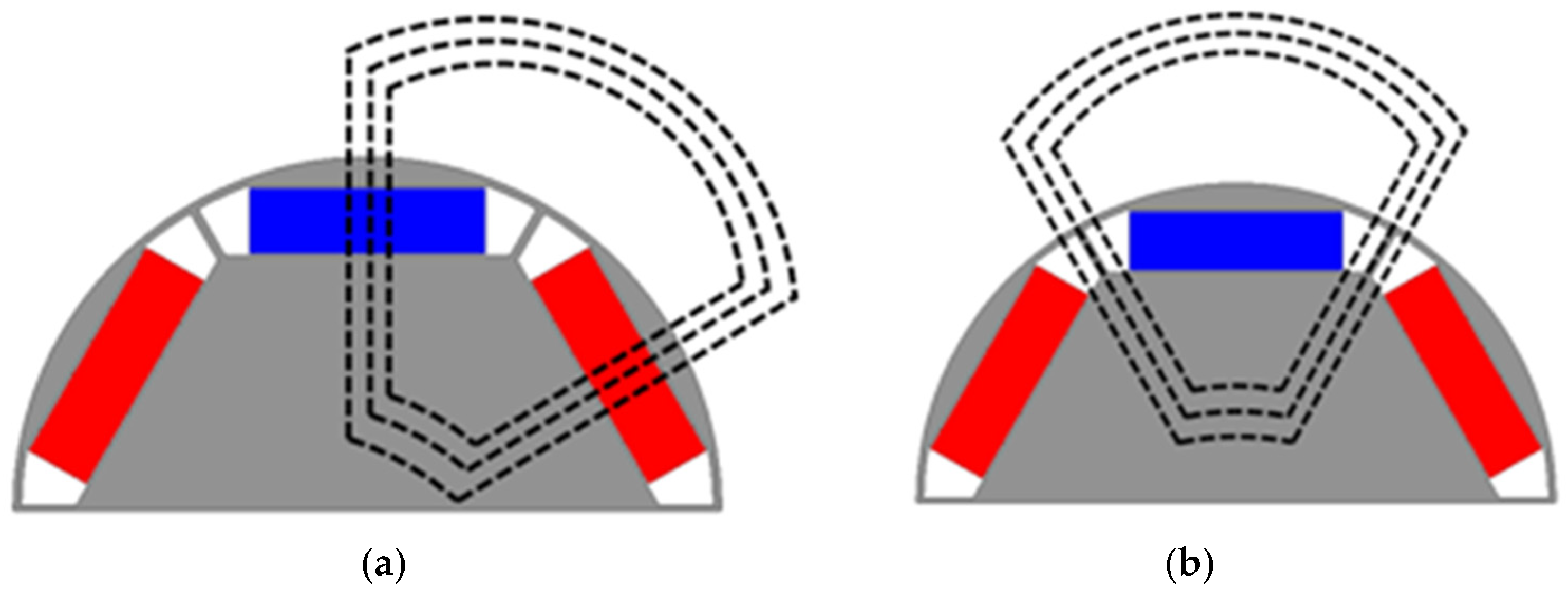
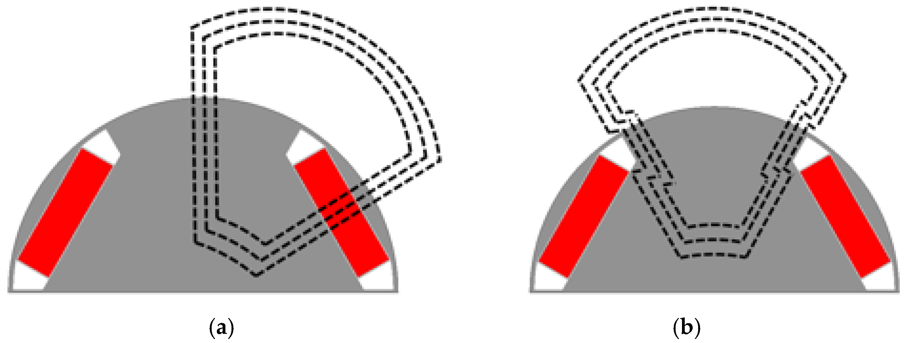
While the previous discussion focused on the characteristics of back-EMF and cogging torque, the characteristics of the CP are here examined from the perspective of reluctance, which affects torque and efficiency under load. The IPMSM has a structure in which permanent magnets are embedded inside the rotor, with the axis of the north pole of the permanent magnet defined as the direct axis (d-axis) and the electrical axis 90° ahead defined as the quadrature axis (q-axis).
Figure 8 shows the d- and q-axis flux paths of the IPMSM, and
Figure 9 shows those of the CP-IPMSM. Since the CP-IPMSM replaces one pole of the magnet with iron, Ld slightly increases due to the reduction in magnetic reluctance in the d-axis path. From the perspective of the q-axis path, flux tends to flow toward the iron side with lower reluctance, resulting in a significant increase in Lq compared with the IPMSM, as confirmed in
Table 2. With the increase in both Ld and Lq in the CP-IPMSM, the difference Lq–Ld becomes larger, which leads to an increase in the reluctance torque component. In other words, applying the CP structure allows greater utilization of reluctance torque. However, the CP has the drawback of increased cogging torque and torque ripple due to flux asymmetry. As previously observed, introducing the ICP structure as a compensating design enables the achievement of sinusoidal EMF and cogging torque reduction.
Therefore, this paper proposes an IPMSM with a new Intersect Consequent Pole (ICP) rotor that addresses the limitations of the CP-IPMSM, such as back-EMF asymmetry, large torque ripple, and high cogging torque. The ICP structure, in which the N-CP and S-CP are alternately arranged over half of the stack length each, demonstrates advantages over the conventional CP-IPMSM by providing a more sinusoidal EMF waveform and lower cogging torque, which are beneficial in terms of vibration and noise. However, the EMF amplitude is lower than that of the CP-IPMSM, indicating performance degradation. The primary cause of this degradation is the axial leakage flux generated by the structural characteristics of the ICP. Because the ICP symmetrically arranges the N-CP and S-CP for half of the stack length each, a new path is formed in which flux from the intersected arrangement leaks axially along the shaft through the core. Therefore, design measures to mitigate axial leakage flux are essential in the ICP structure, and this study proposes a design to reduce axial leakage flux.
4. Intersect-Type Dual Rotor Structure Proposal and Improvement
4.1. Design Parameter Setting
The rotor design parameters selected in this paper are shown in
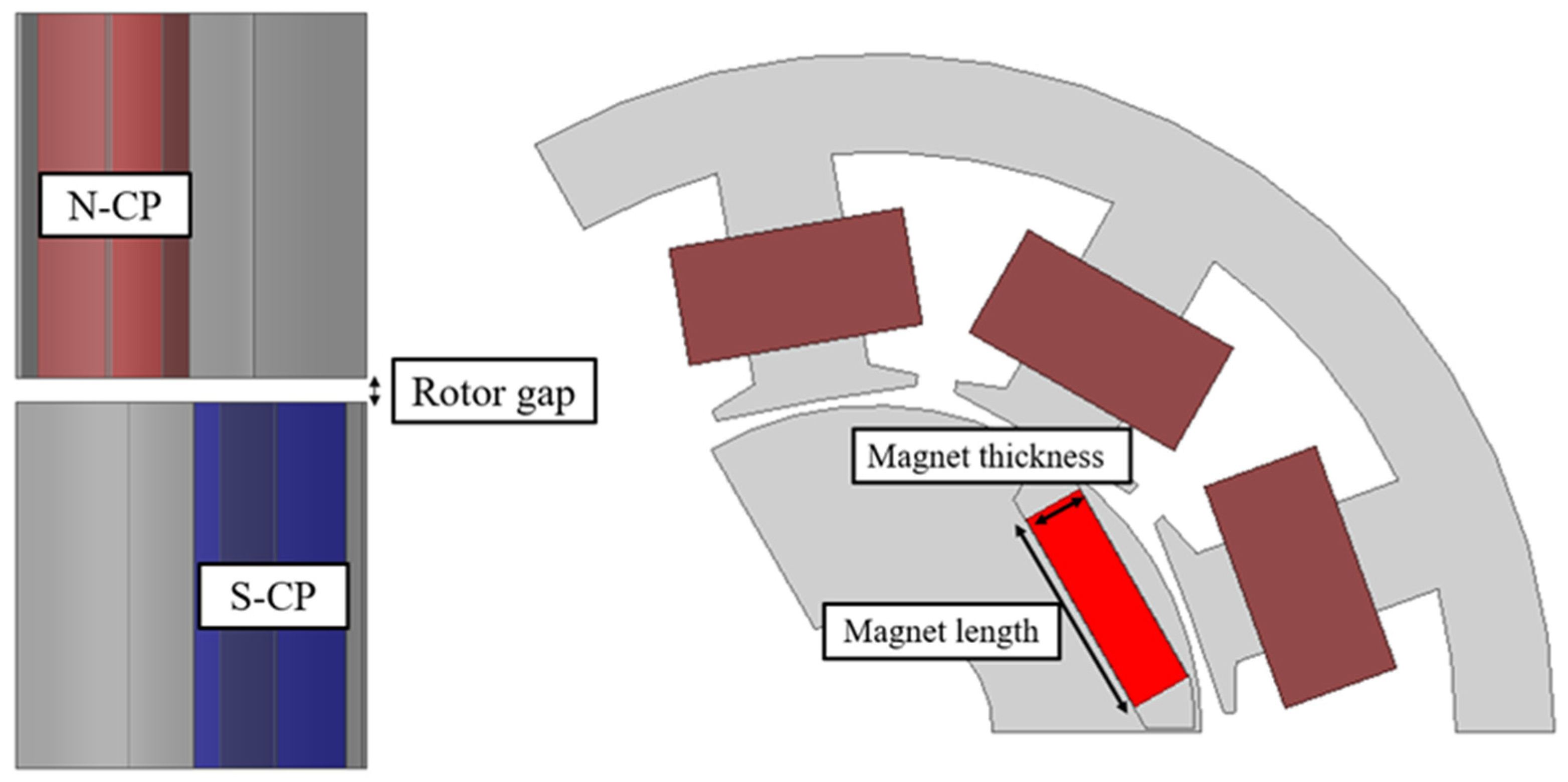
Figure 10. The magnet length of the permanent magnet and the gap between the halves of the rotor core stack were chosen as design variables. For the magnet width, irreversible demagnetization of the magnet must be considered; therefore, it was initially set to the same thickness as in the conventional design before further design was carried out. In addition, for the stator, only the rotor was optimized while maintaining the stator shape of the conventional motor, ensuring normal operation without incurring additional costs in the existing manufacturing process.
4.2. Rotor Gap Selection for Axial Leakage Flux Reduction
Since the ICP arranges the N-CP and S-CP in an intersecting manner, a new path is formed in which flux leaks axially through the core, making an improved design essential. In this study, to reduce axial leakage flux, a rotor gap—an additional air gap—was introduced between the N-CP and S-CP. The rotor gap provides high magnetic reluctance in the flux path, blocking the flow of leakage flux that previously passed through the core.
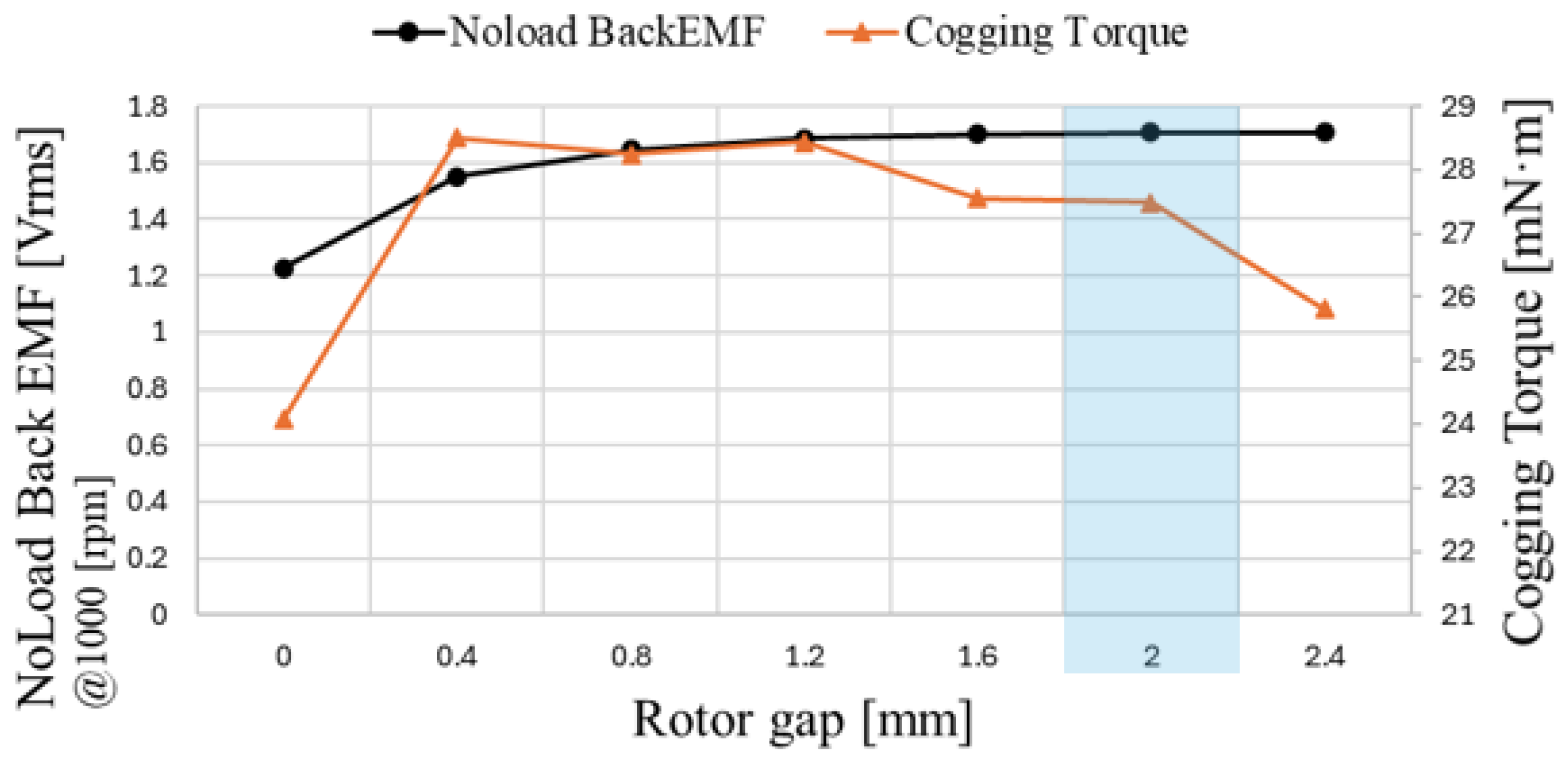
Figure 11 shows the tendencies of back-EMF and cogging torque as a function of rotor gap length. As the rotor gap increases from 0 mm, the back-EMF gradually increases, while the target cogging torque remains below 50 mNm. Furthermore, the flux density plot in
Figure 12 shows that saturation in the contact region between the N-CP and S-CP is alleviated, indicating that the rotor gap effectively blocks axial leakage flux. However, when the gap length increases beyond a certain point, the rotor stack length decreases relative to the fixed stator stack length, resulting in only marginal performance improvement. Therefore, proper length selection is critical, and the rotor gap length was determined to be 2 mm, which is within the safe margin for back-EMF improvement.
4.3. Permanent Magnet Length Selection
In the ICP-applied model, even though a rotor gap was introduced to suppress the axial leakage flux component, achieving the target torque with only 50% magnet usage is difficult. Therefore, more than 50% magnet usage is required, and adjusting the magnet width is important for achieving a uniform air-gap flux density. In the case of a 6-pole PMSM, the pole pitch angle is 360/6 = 60°, and for the 6-pole configuration, the angular span between the two ends of a magnet cannot exceed 60°.
Accordingly, the magnet length was examined for cases where the bottom-end vertices of the magnet in the rotor center direction coincide with the 60° pole pitch region. As the magnet length increases, the no-load back-EMF also increases; however, cogging torque increases simultaneously, and therefore the magnet length must be selected considering this trade-off. Meanwhile, the magnet thickness was kept the same as that of the conventional motor to ensure robustness against irreversible demagnetization.
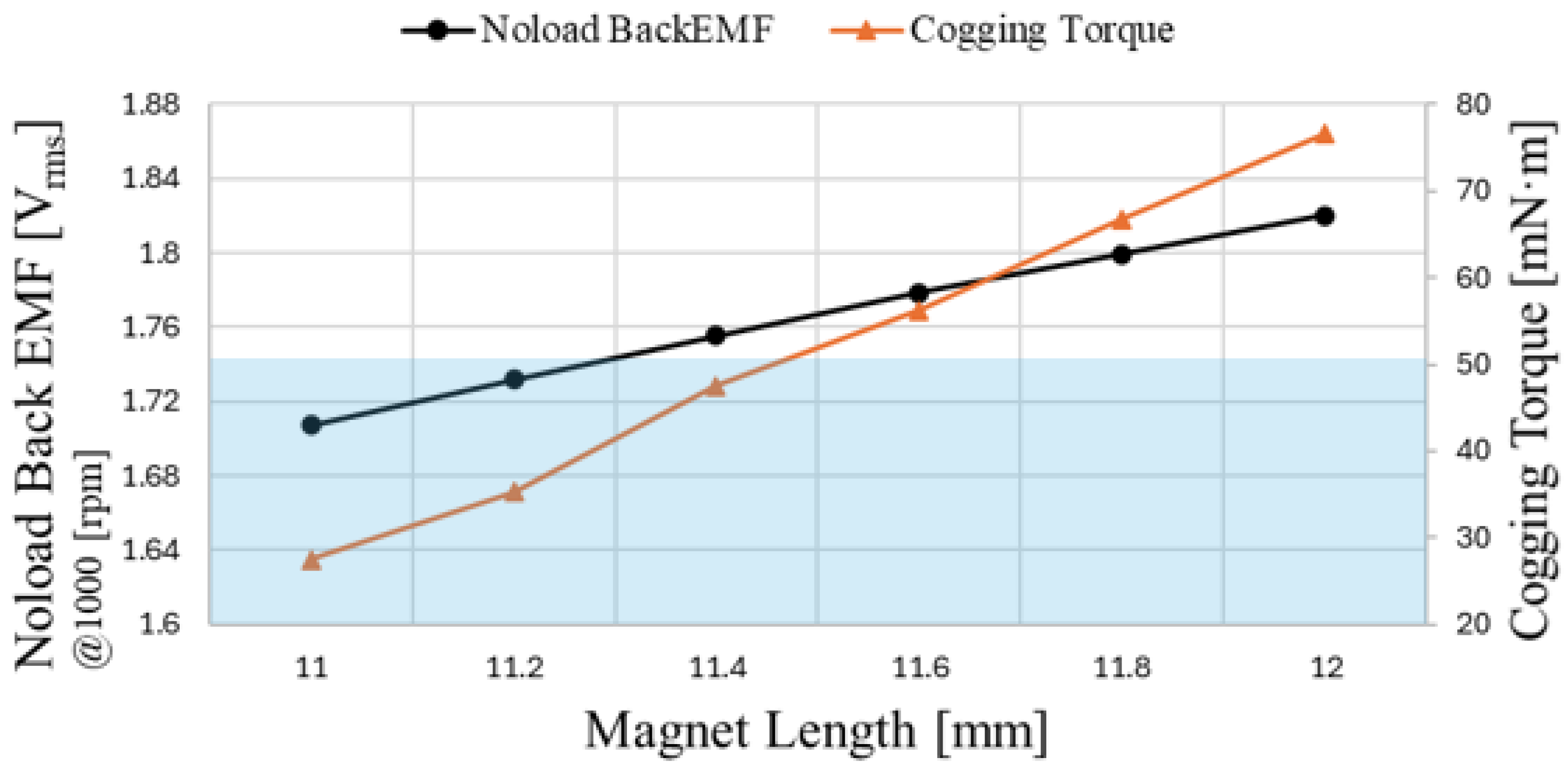
Figure 13 shows the trend of no-load back-EMF and cogging torque when the magnet length of the conventional motor is increased from 11 mm to 12 mm. As the magnet length increases and magnet usage grows, the back-EMF also increases; however, cogging torque increases as well. This result indicates that increasing the magnet length not only enhances performance but also amplifies the ripple components in the cogging torque waveform. For the target EPS motor, it is important to minimize vibration and noise. Therefore, reducing unnecessary components that cause vibration and noise is critical, and one such component is cogging torque.
Cogging torque is generated by the tendency of the rotor’s permanent magnets to align with the stator teeth and slots due to differences in magnetic reluctance, as the rotor seeks the path of minimum reluctance. Unlike torque that contributes to rotation, cogging torque alternates between positive and negative values as the motor rotates, providing no benefit to motor torque and instead causing vibration and noise. Therefore, for the EPS motor, where low vibration and noise are essential, it is important to select a magnet length that achieves the highest no-load back-EMF while maintaining cogging torque below the target of 50 mNm. In this paper, the magnet length was determined to be 11.4 mm.
The reason cogging torque increases with longer magnet length can be understood from
Figure 14. As the magnet length increases, when the rotor rotates and the center axis of the rotor magnet aligns with the stator tooth—where cogging torque would normally decrease—flux begins to flow first toward the adjacent tooth, generating a force to align with it. This phenomenon results in an increase in cogging torque.
Figure 15 shows the flux lines at a magnet length of 11.4 mm, where most of the flux from a single magnetic source links with one tooth, confirming that the target cogging torque requirement is satisfied.
The governing equation of cogging torque is expressed in (1), where
is the stack length, D is the rotor outer diameter,
,
is the least common multiple (
) of the number of slots and poles,
is the nth harmonic of the airgap permeance and
is the rotor mechanical angle. Since cogging torque is generated by the difference in magnetic reluctance between the slots and the permanent magnets, its period can be expressed in mechanical angle.
Here,
denotes the least common multiple. When expressed in electrical angle, it can be written as (3).
Therefore, Equation (3) confirms that the cogging torque waveform in
Figure 15b repeats with a period of 60°.
4.4. Maximum Torque per Ampere (MTPA) Control
The selected magnet length of 11.4 mm yields a shaft torque under load of 2.96 Nm. The application target is ≥3 Nm, corresponding to a 1.33% shortfall. While reducing permanent magnet usage is an important objective, meeting the target output takes priority. As shown in
Section 3 (
Table 2), the CP structure replaces one permanent magnet pole with iron; flux preferentially follows the lower-reluctance path, increasing
and enlarging
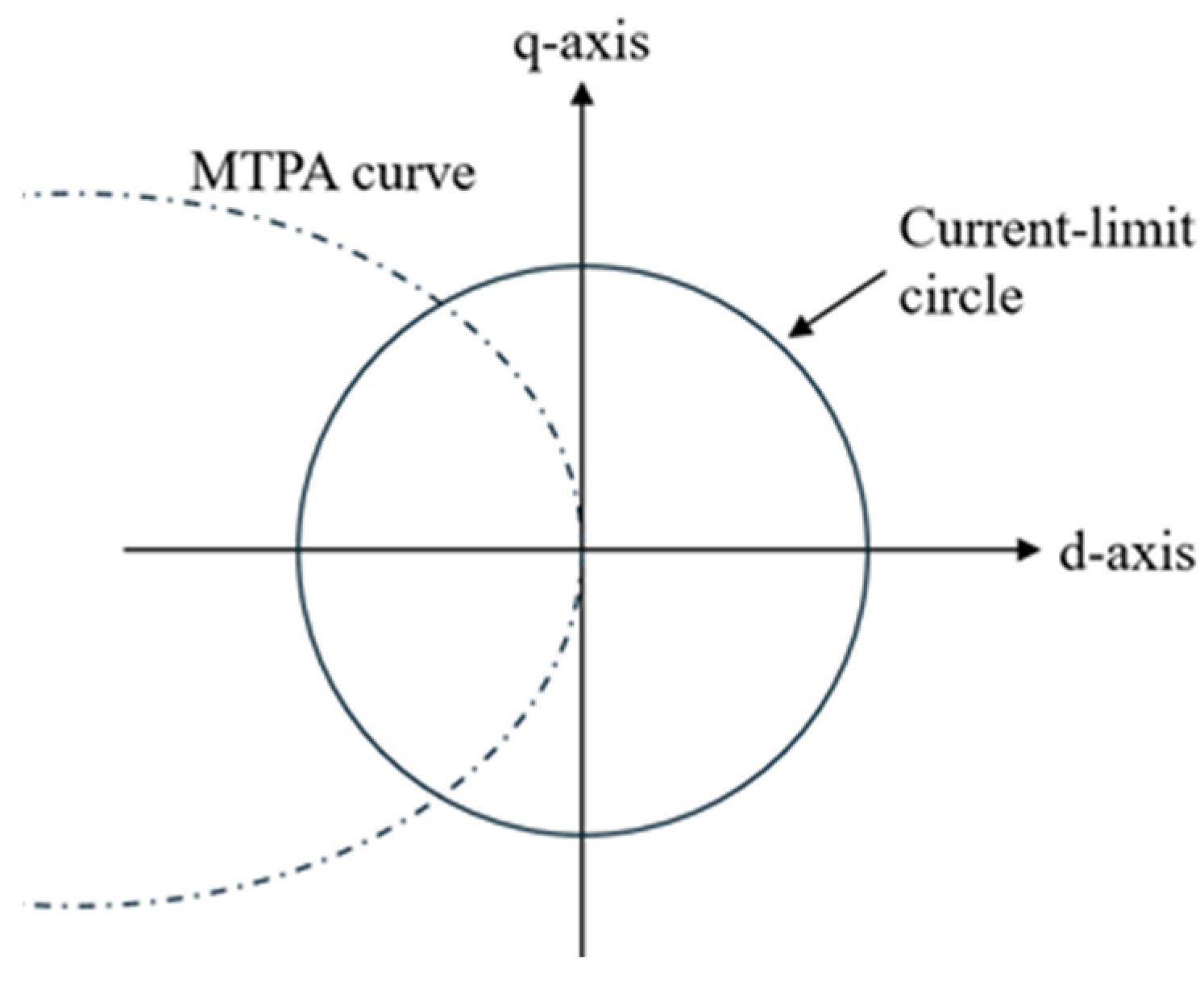
, thereby increasing the reluctance-torque component. Accordingly, to maximize torque under the same current constraint, the maximum-torque-per-ampere (MTPA) control method was applied. Under MTPA, the current magnitude is held constant while the current phase angle
β is varied to exploit the d-axis and q-axis current components. The optimal current phase angle is obtained by enforcing
in torque Equation (4).
The torque equation is given in (4), where
is poles,
is the permanent magnet flux linkage,
is the magnitude of the current vector, the term
represents the magnetic torque (
), while
represents the reluctance torque (
) generated by saliency. The MTPA control is performed by partially differentiating (4) with respect to the current phase angle and setting the result to zero.
When
, the generated torque reaches its maximum, and the d-axis current (
) and q-axis current (
) at this point can be expressed by (6) and (7).
Using these equations to plot the trajectory of the current vector as the current magnitude varies yields the MTPA curve shown in
Figure 16.
In this section, both the conventional model and the ICP model were analyzed by deriving the optimal angle through MTPA control, and the values of Ld, Lq were calculated at that operating point.
The applied current magnitude was identical for both models, with the conventional model having
and the ICP model having
. As shown in
Table 3, the utilization of reluctance increased in the ICP model, and
expanded by 14.7% compared with the conventional model.
The torque equation for an IPMSM is given in (4); the reluctance component is = . Since the pole count and current are identical between the ICP and conventional models, a relative comparison index is . Substituting the respective values and evaluating the ICP-to-conventional ratio yields an increase of approximately 1.57% in the utilization of the reluctance component. This occurs because, although in the ICP decreases from to , slightly reducing , increases by about 17.23%, which outweighs the reduction in the angular term. Consequently, the utilization of reluctance torque increases, and the torque rises from 2.96 Nm to 3.04 Nm (+2.70%), satisfying the target torque.
However, when MTPA control is applied to increase the reluctance torque term by controlling the d-axis current, flux tends to concentrate along the d-axis. In addition, since the CP replaces one magnetic pole with iron, the armature reaction flux may concentrate on the iron-side path, which has relatively lower magnetic reluctance. Consequently, the remaining magnets are exposed to a concentrated armature reaction flux, thereby increasing the risk of irreversible demagnetization. For this reason, irreversible demagnetization analysis of the ICP-IPMSM is essential under the same operating point as the conventional motor.
Figure 17 shows the irreversible demagnetization analysis results of the conventional motor and the ICP-IPMSM.
At this point, the demagnetization analysis was conducted in 2D, assuming that the rotor gap suppressed the axial leakage flux of the rotor. The analysis was performed at 100 °C, under which irreversible demagnetization does not occur in the conventional motor. It was confirmed that in the ICP-IPMSM, which reduced magnet usage by 48.2%, demagnetization occurred at less than 1%, effectively negligible.
4.5. Additional Irreversible Demagnetization Review by Magnet Thickness
In the proposed ICP-IPMSM, the magnet thickness was fixed to be the same as that of the conventional motor, and only the magnet length, i.e., the pole arc ratio, was adjusted to evaluate the electromagnetic effects of geometric changes such as EMF and cogging torque. The reason for keeping the magnet thickness constant was to maintain the thickness-to-airgap ratio, which primarily governs irreversible demagnetization at the operating point, thereby preserving the main influence of the permeance coefficient (the slope of the load line) while observing performance changes due to length variation. Under this condition, analysis of the ICP-IPMSM confirmed that irreversible demagnetization did not occur.
However, in ICP motor design, since the armature reaction flux tends to flow through the iron-side path with relatively lower magnetic reluctance, a structure can form where the remaining magnets are exposed to concentrated armature reaction flux. Therefore, even if a quantitative analysis of irreversible demagnetization has been conducted, additional verification is required to ensure a sufficient safety margin against irreversible demagnetization.
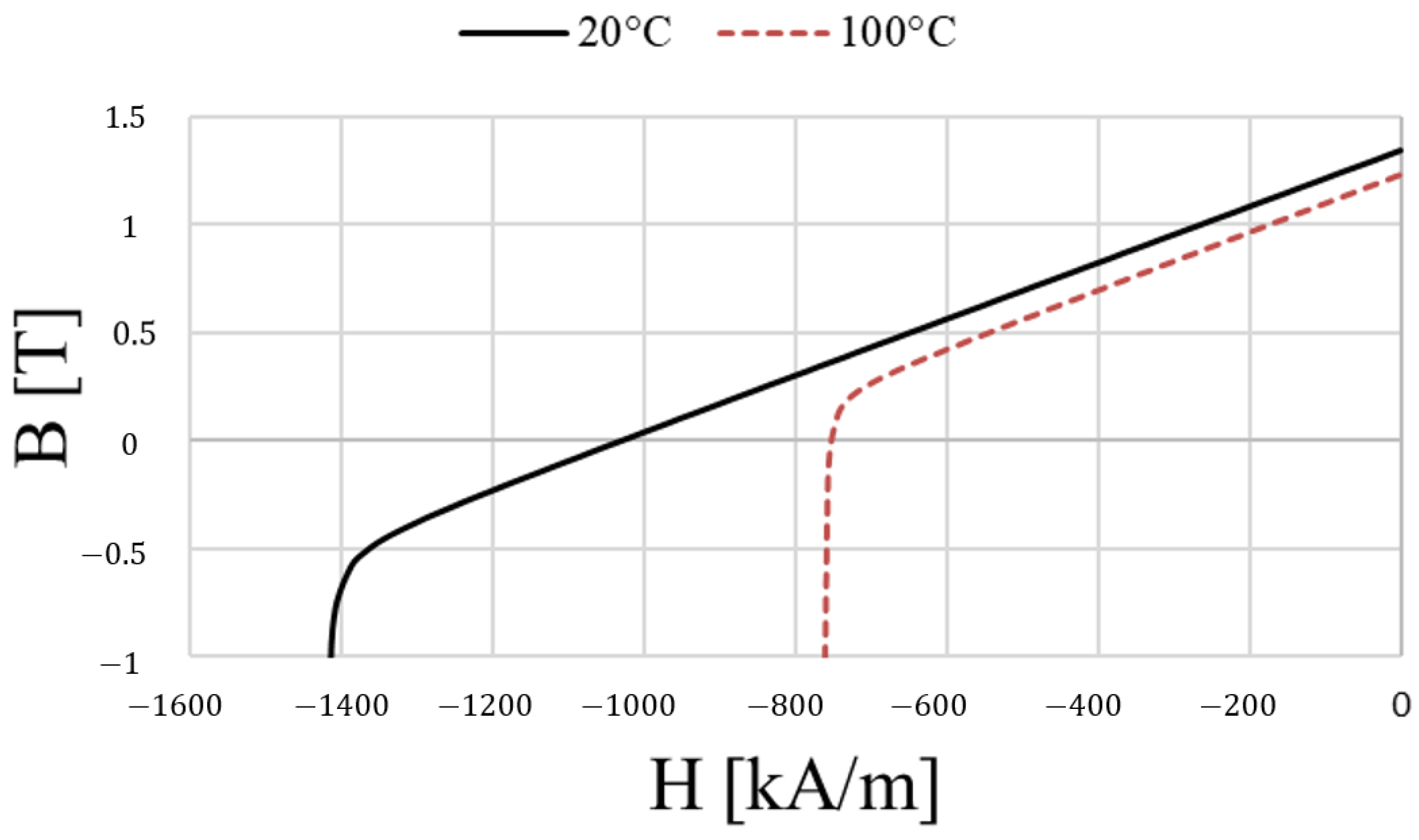
Figure 18 shows the operating curve of N45H used in the ICP motor. In the B–H curve, the first quadrant generally represents the initial magnetization process of the permanent magnet material, while actual operation occurs in the second quadrant; hence, only the second quadrant is presented. In this operating curve, irreversible demagnetization occurs starting from the knee point, where the nonlinear region of coercivity begins. Accordingly, in this section, in addition to the design that considered performance improvement and cogging torque effects due to magnet length variation, irreversible demagnetization was further verified with respect to magnet thickness.
Based on the baseline magnet thickness of 3.1 mm in the original model, an irreversible demagnetization analysis was performed, including a thinner 2.6 mm case and a thicker 3.6 mm case. For all thicknesses, under identical operating and temperature conditions, the temperature-dependent intrinsic coercivity from the datasheet
Figure 19.
, was used as the acceptance criterion, and the maximum reverse field within the magnet volume,
, was evaluated to compute the demagnetization safety margin. The margin was defined as
. The results were as follows: for 2.6 mm,
with S = 10.19%; for 3.1 mm,
with S = 10.73%; and for 3.6 mm, no irreversible demagnetization was observed. In all cases, no irreversible demagnetization relative to
was found, and a sufficient margin was secured. Therefore, a change in magnet thickness was not deemed necessary, and the final design adopted the same 3.1 mm thickness as the baseline.
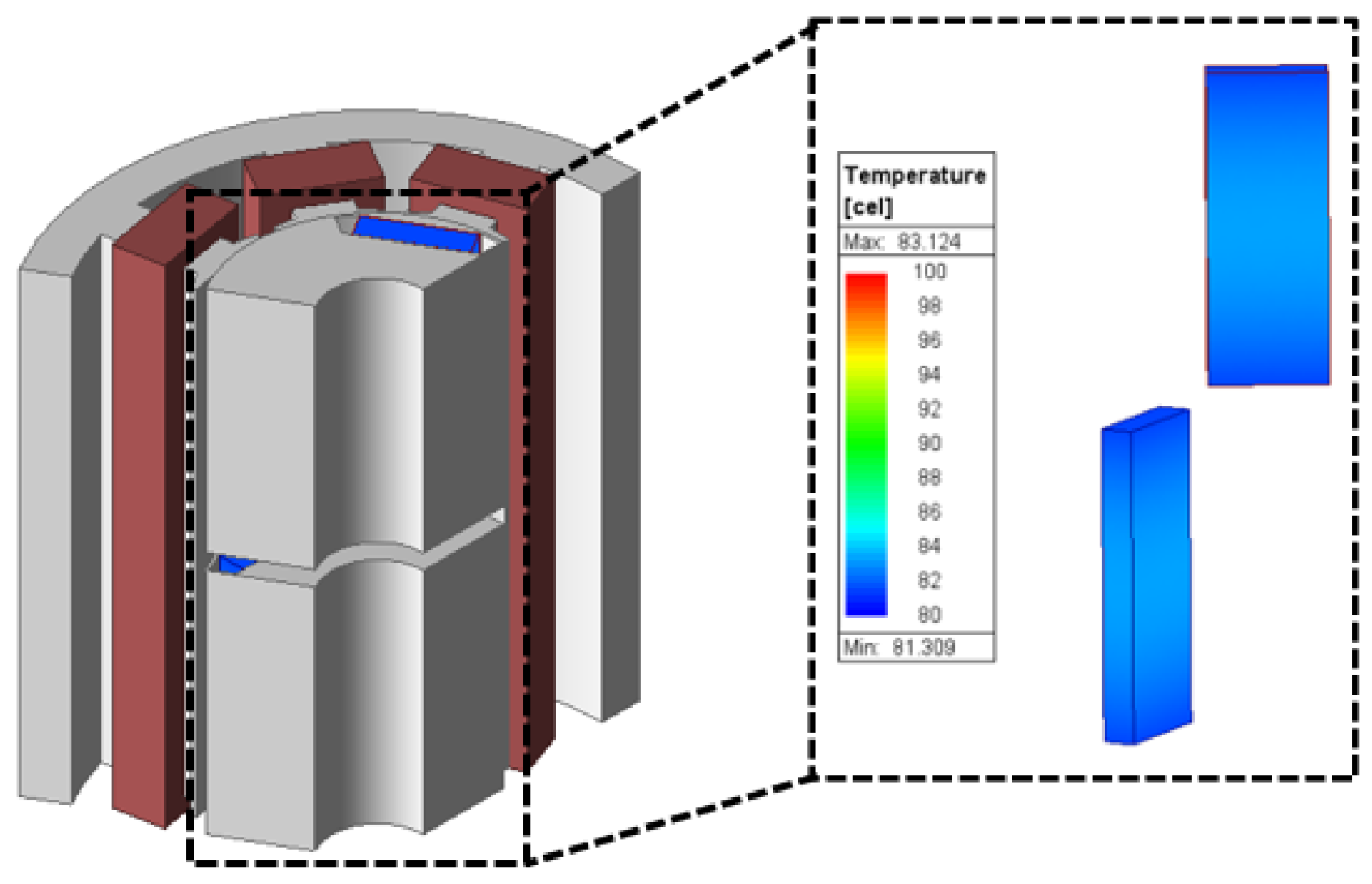
Additionally, under room-temperature conditions (ambient 20 °C); convection coefficient 30 W/m
2·K on the housing outer surface, a steady-state thermal analysis was performed, yielding a peak magnet temperature of 83.1 °C as shown in
Figure 20. The thermal boundary conditions applied natural convection only to the housing outer surface, while the interior provided a continuous conduction path across the magnet–rotor, rotor–stator, and stator–housing interfaces. The thermal analysis was conducted in Ansys Electronics 2024 R1, Mechanical Design (steady-state thermal), and the copper loss, core loss, and permanent magnet (PM) eddy-current loss calculated in the electromagnetic analysis (Maxwell) within the same software were mapped to each component as volumetric heat sources.
The peak magnet temperature of 83.1 °C was obtained from
Figure 19 by linear interpolation with respect to temperature, giving
(83.1 °C) = 811.25 kA/m. Under these conditions, the safety margin S was 15.86% (2.6 mm) and 16.37% (3.1 mm), indicating that the magnet thicknesses considered in this study have a low likelihood of irreversible demagnetization at the operating point.
5. Performance Analysis of the Final Model
In selecting the final model, the flux density in the core under load current becomes an important design parameter. If the flux density is excessively high, magnetic saturation occurs, which can affect performance.
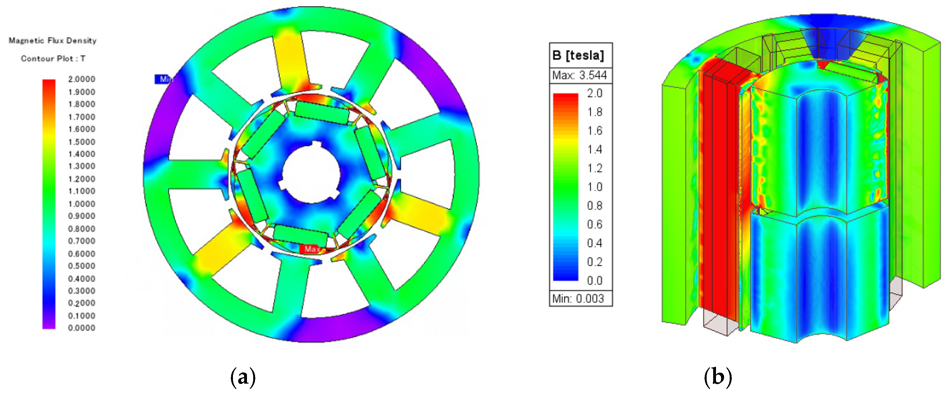
Figure 21 shows the magnetic saturation under load for the conventional motor and the final model. As shown in the figure, the rotor core magnetic saturation levels of the conventional model and the final model are similar; however, in the ICP-IPMSM, the tooth saturation level is observed to increase. This is attributed to the characteristic of the CP model, in which the magnetic reluctance of the iron-pole side becomes lower than that of the magnet side, resulting in flux asymmetry.
Based on the results derived from the previous analyses, this study selected a rotor gap of 2 mm and a magnet length of 11.4 mm for the final design. This combination meets the target performance by suppressing axial leakage flux, enabling more efficient magnetic loading, and increasing utilization of
.
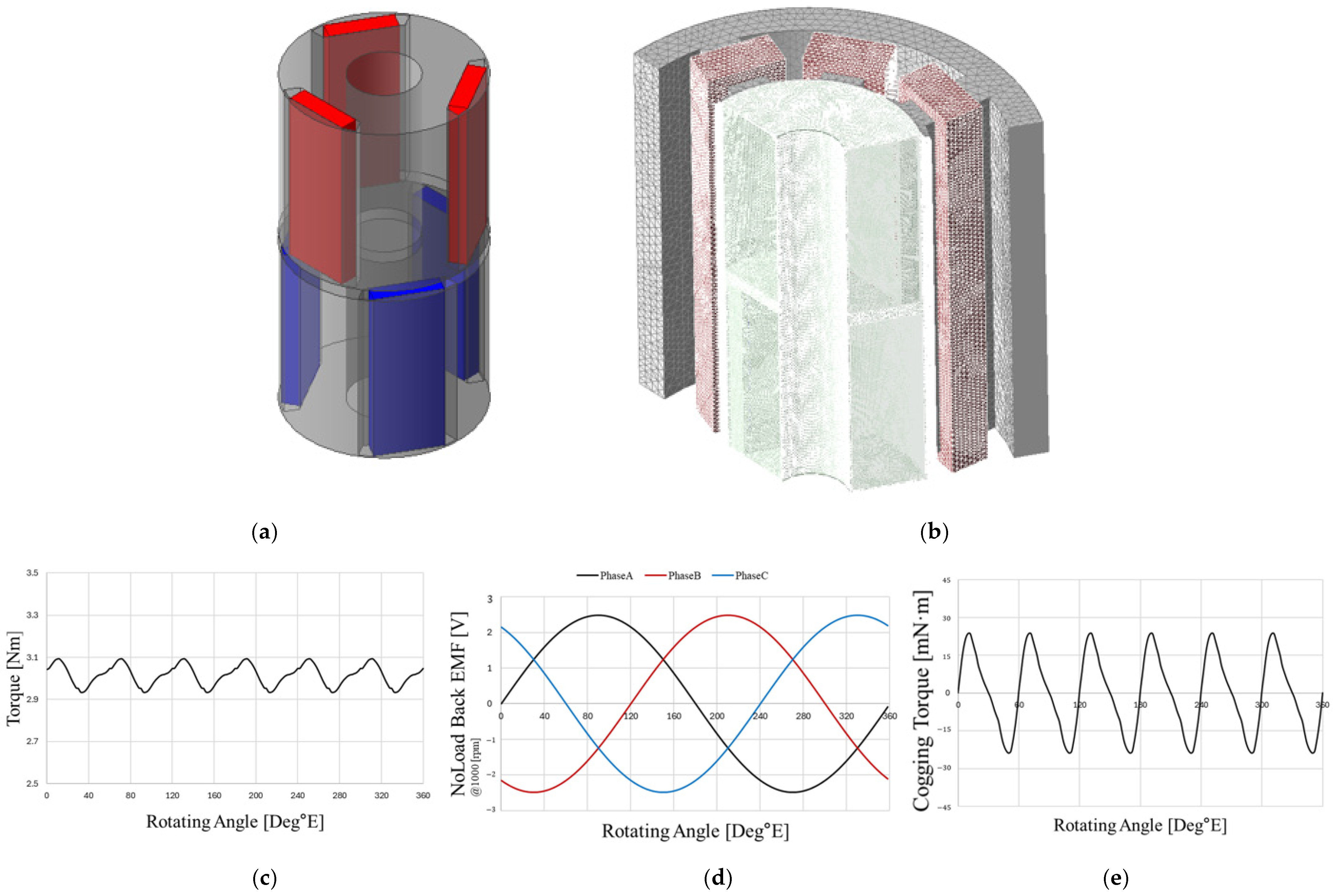
Figure 22 shows the final ICP rotor geometry, representative analysis conditions (mesh), and the resulting key performance metrics;
Table 4 summarizes the principal metrics for the baseline and final models. As shown in
Table 4, although the EMF is lower than in the baseline, the torque is comparable, indicating equivalent performance within the target specifications. This outcome arises from the increased contribution of reluctance torque, which is an inherent advantage of the CP topology. According to (4), reducing the magnet volume lowers
, but the MTPA β shifts toward the −d axis, thereby increasing the contribution of
.
One characteristic of the ICP is that replacing one pole with iron reduces magnetic reluctance along the d-axis path, slightly increasing
, while, from the q-axis perspective, the flux is guided through the lower-reluctance iron path, increasing
to a greater extent. Consequently,
increases; the MTPA locus on the d–q plane
Figure 16 shifts further toward −d axis; and the torque–current characteristic yields torque comparable to the baseline at the same current.
Regarding losses, copper loss is identical because the stator, winding, and applied current are the same. Core and eddy-current losses are higher than in the baseline; this is attributable to flux asymmetry associated with the CP structure and a larger magnet face area, which increases the eddy-current loop area and susceptibility. Nevertheless, these increases remain within specification, and the targets for torque as well as cogging torque and torque ripple (NVH drivers) are satisfied. In addition, considering the cost and supply benefits of rare-earth reduction, we believe this approach offers clear advantages.
Table 5 compares the rotor material costs of the baseline and final models using conservative unit prices that account for market volatility for the materials considered—electrical steel (35PN230) and permanent magnets (N45H). As shown in the table, rotor material cost is dominated by the permanent magnets, and the proposed geometry directly reduces this dominant component, yielding a clear cost advantage from a manufacturing standpoint. In EPS systems, where product cost and resource-risk management are critical, reducing permanent magnet usage has substantial system-level value.
Three-dimensional finite element analysis (3D FEA) was used, and a representative mesh distribution is shown in
Figure 22b. All electromagnetic analyses were performed with Ansys Maxwell 2024 R1 using a 2D periodic sector of (360
/2P)with a moving band. Master–slave periodic boundaries were applied to the sector side faces, and a zero-tangential H-field boundary was imposed at the outer boundary. Material interfaces (PM–core, core–air gap, etc.) were treated using Maxwell’s default field-continuity conditions without additional contact impedance. The reference operating condition was 1000 rpm, 57.7 Arms, and 20 °C; for the demagnetization analysis, the temperature was 100 °C. The mesh employed local refinement in the air gap, with a minimum element size of 200 μm and a total of 5,262,285 elements.
6. Conclusions
This study focused on the design and analysis of an EPS motor. In EPS motors, vibration and noise significantly influence smooth operation and control precision. Moreover, because rare-earth magnets—one of the key components of motors—face supply issues and cause environmental pollution during mining, reducing rare-earth magnet usage is essential. To address this, the Consequent Pole (CP) structure was proposed. However, when the CP structure is applied, one pole is replaced with iron, which increases the risk of torque ripple due to magnetic reluctance imbalance.
To mitigate this, we propose an Intersect CP (ICP) configuration that interleaves an N-CP over half of the lamination stack and an S-CP over the remaining half to reduce flux-distribution asymmetry. Although a 50% reduction in permanent magnet usage inherently degrades performance. In this study, under identical stator conditions, we increased the magnetic loading ratio and adopted a loading-ratio–based design; with MTPA control, increased by 17.23%, thereby enhancing the reluctance-torque component. Consequently, in the proposed ICP design, permanent magnet usage was reduced by 48.2% while meeting the 314 W target output, and total cost decreased by 42.24%. Therefore, the proposed ICP design is a viable alternative for EPS motors requiring reduced rare-earth magnet usage, maintaining equivalent performance while lowering cost and environmental impact. Furthermore, by applying ICP to a radial-flux IPMSM and linking design, control, and reliability within a unified framework under identical ratings and stator constraints, this study demonstrates both practical feasibility and academic significance, supported by quantitative verification.
