1. Introduction
BLDC motors have been extensively adopted in modern electromechanical systems due to their high power density, efficiency, and durability compared to conventional brushed machines [
1]. Unlike brushed motors, where mechanical commutation is achieved through brushes and a commutator, BLDC motors rely on electronic commutation governed by rotor position feedback. This design eliminates mechanical wear components, significantly improving reliability and reducing maintenance requirements. Such advantages have made BLDC motors a preferred choice in diverse applications, including robotics, electric vehicles, unmanned aerial systems, precision automation, and biomedical devices [
2,
3]. In particular, robotic and mechatronic systems impose stringent demands on actuators, requiring lightweight construction, compact integration, high torque-to-weight ratio, and precise position control. Meeting these requirements has driven research into novel BLDC motor designs that not only optimize electromagnetic performance but also incorporate features for sensor integration, compact packaging, and dynamic response.
Traditionally, the fabrication of BLDC motors has relied on subtractive manufacturing methods such as machining, stamping, and lamination. While these methods yield high-performance machines with optimized electromagnetic cores, they are constrained by the geometry achievable through conventional processes. Recent advances in additive manufacturing technologies, such as fused deposition modeling and composite 3D printing, provide opportunities to overcome these constraints by enabling the production of custom, lightweight, and geometrically complex components at relatively low cost and short turnaround times [
4,
5]. In the context of BLDC motors, additive manufacturing has been used to prototype housings and rotors, demonstrating the feasibility of rapid motor prototyping and design customization. One key advantage of 3D printing is the ability to realize hollow-shaft topologies, which are increasingly important in robotic actuators where through-axis cabling, weight reduction, and the integration of secondary components are required. Hollow-shaft configurations reduce the polar moment of inertia, thereby enabling improved transient dynamics such as faster acceleration and deceleration, which are crucial for legged robots, robotic arms, and other precision systems.
An essential aspect of BLDC motor operation is accurate rotor position sensing, which is necessary for electronic commutation and closed-loop control. Hall-effect sensors are widely used for detecting rotor position due to their simplicity, reliability, and low cost. Precise sensor placement relative to the rotor poles is critical to ensuring correct commutation sequences and minimizing torque ripple. Beyond Hall sensors, high-resolution encoders are also required in applications involving precision motion control, such as robotic manipulators and autonomous systems. In addition, the motor controller plays a pivotal role, responsible for commutating motor phases, regulating position, and ensuring robust communication with higher-level control systems. Recent developments in embedded electronics and power conversion circuits have facilitated the integration of compact yet powerful motor controllers, which are indispensable for achieving high-performance robotic actuators.
Akula et al. [
6] study the feasibility of fabricating BLDC outrunner rotors using FDM-based 3D printing with PLA composites. Experimental tests comparing 3D-printed and conventional metal rotors show comparable thrust performance, while achieving significant weight reduction. The results highlight the potential of 3D-printed rotors to enhance UAV endurance, reduce costs, and enable customized motor designs.
Shekhar et al. [
7] introduced a low-cost modular actuator for robotics, fabricated using additive manufacturing and hobby-grade BLDC motors. The actuator design incorporates 3D-printed planetary gears and custom control electronics, including Arduino and later ESP32 with DRV8305 drivers and AS5147 encoders. Experimental results show competitive torque and performance compared to commercial actuators like GIM8008, at about one-fourth the cost.
Works by Sergio et al. [
8] present the design and control of a 3D-printed permanent magnet synchronous motor (PMSM) using PETG material and a Halbach array configuration. A model-based adaptive controller, implemented on Arduino, is developed from system identification to achieve accurate speed reference tracking. Experimental results validate the prototype’s performance, showing stable operation, minimal tracking error, and effective thermal behavior under steady-state conditions.
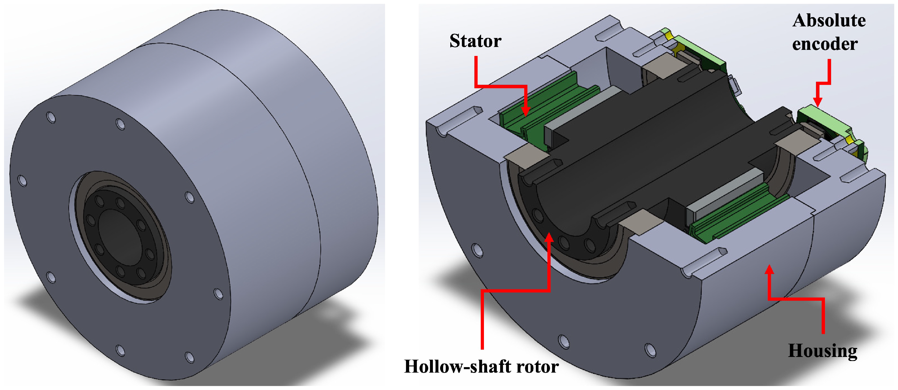
While additive manufacturing has been explored in various electromechanical applications, prior studies have seldom applied 3D-printing techniques directly to the rotor and stator of BLDC motors. Addressing this gap and building on the opportunities it creates, this paper presents the design, fabrication, and experimental validation of a custom 3D-printed BLDC motor with integrated sensing and control, as illustrated in
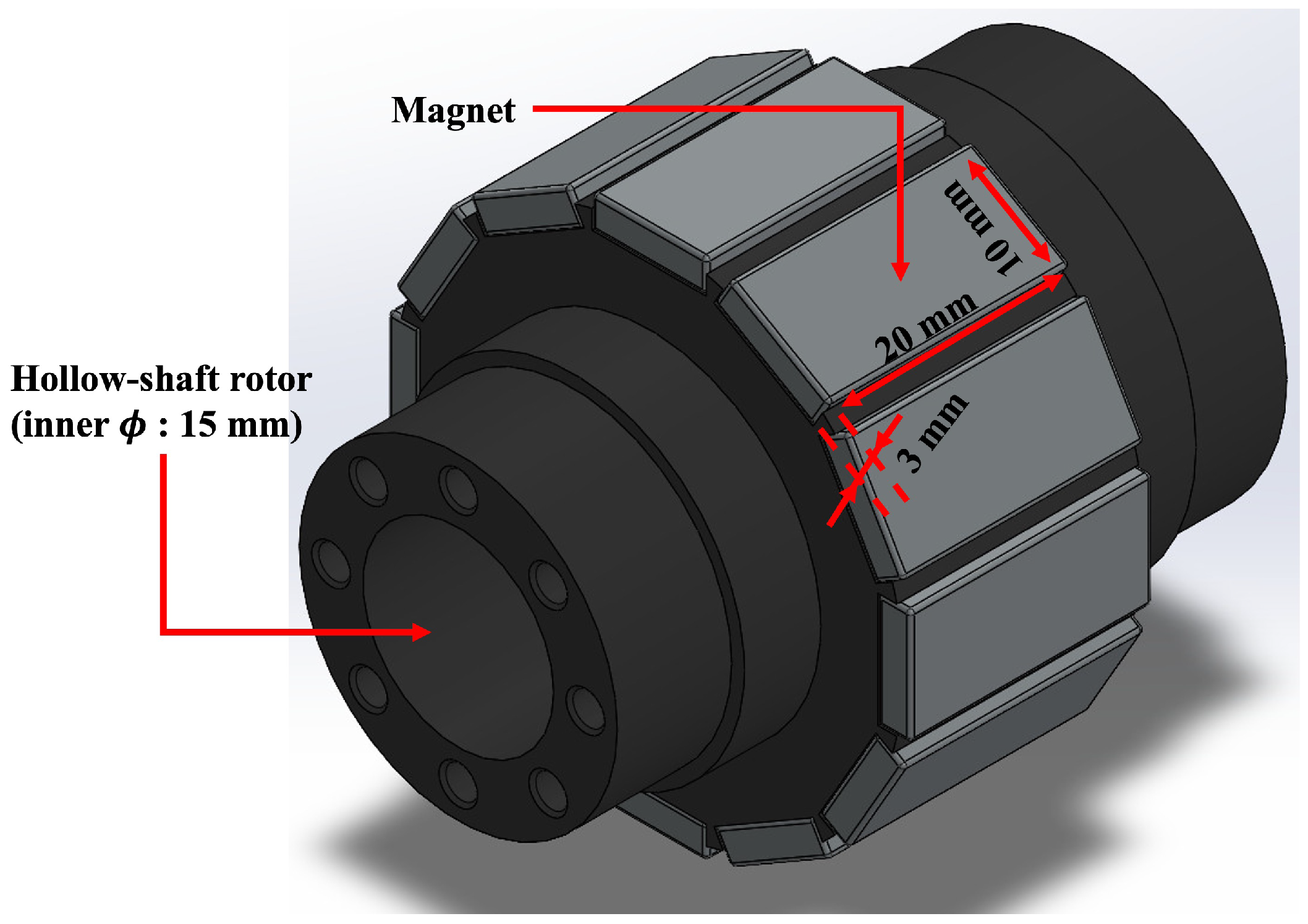
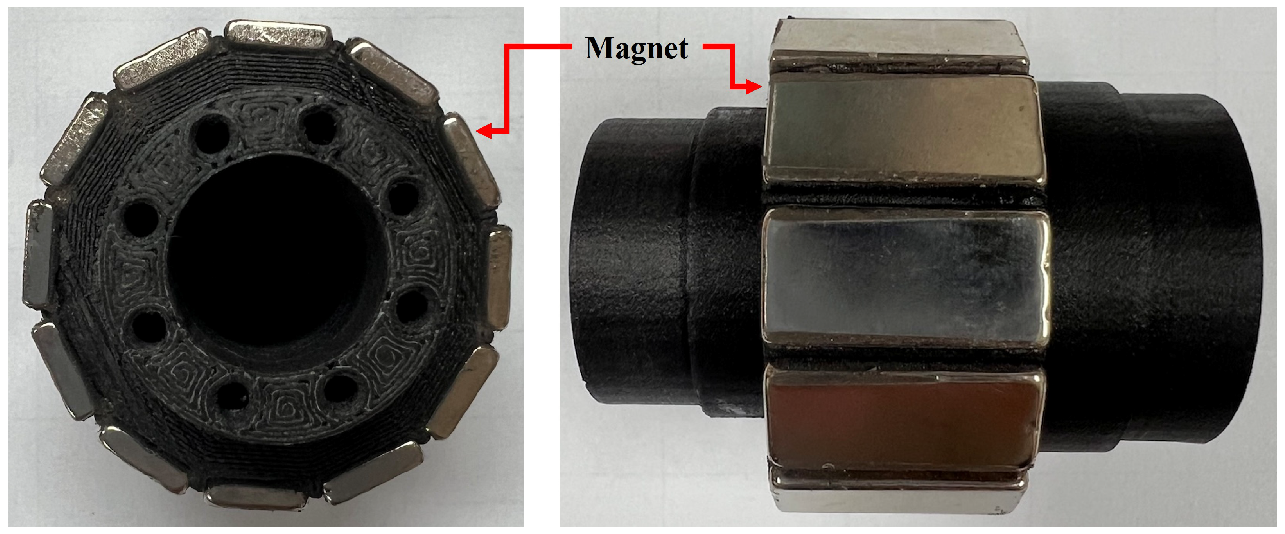
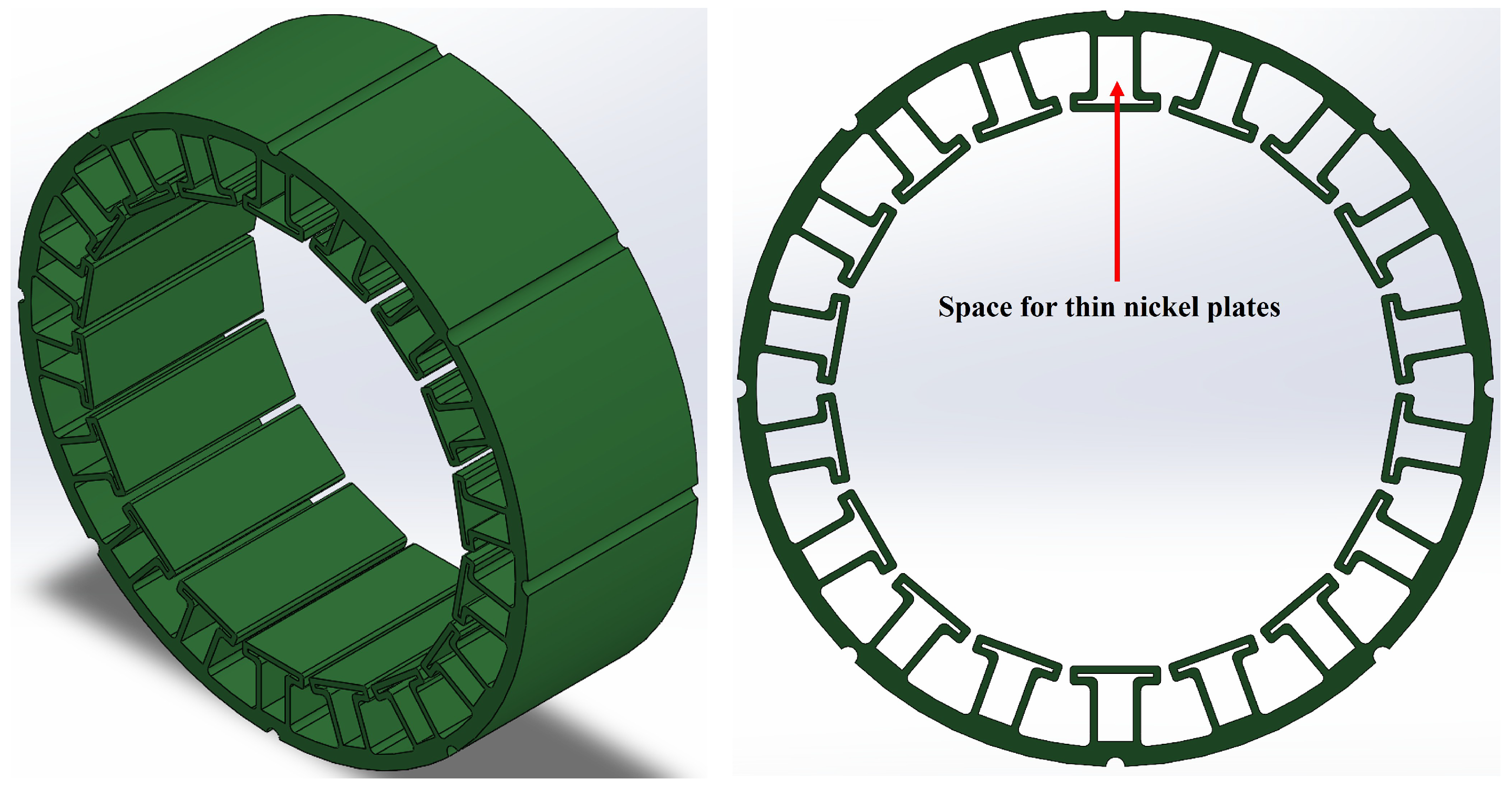
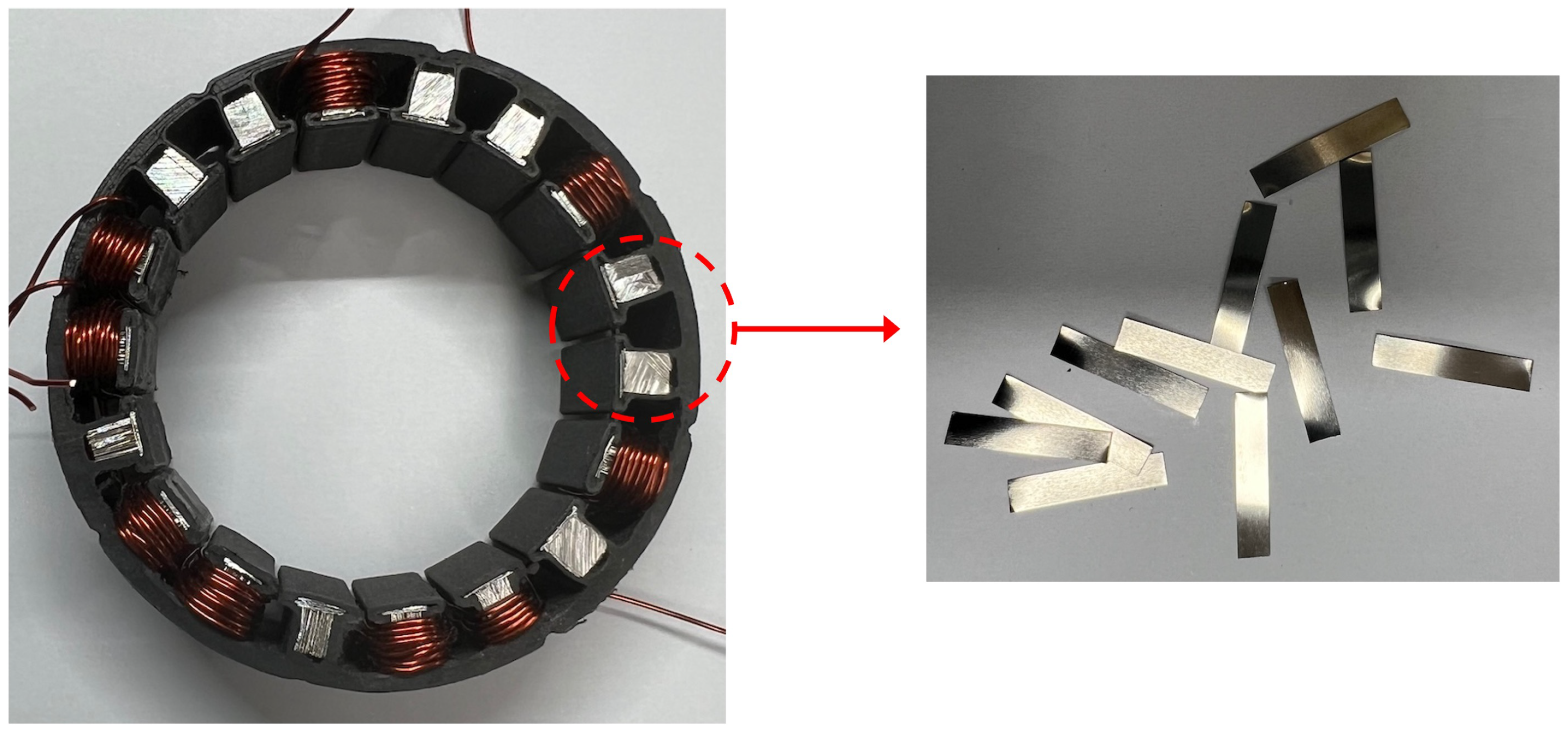
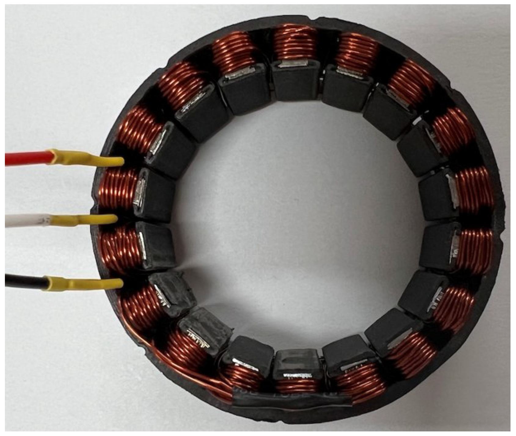
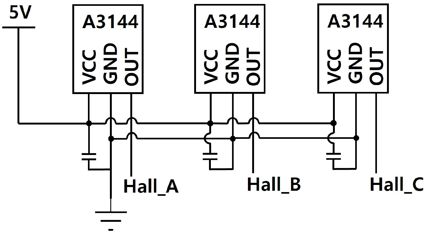
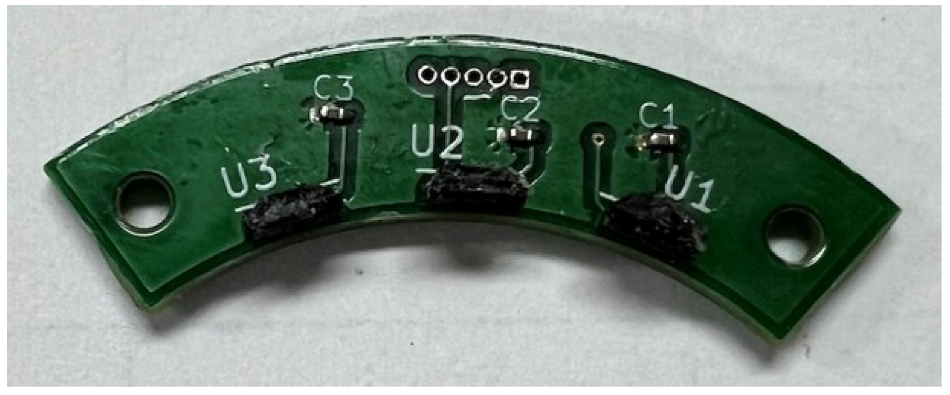
Figure 1. The rotor is designed as a hollow-shaft configuration and equipped with twelve high-energy NdFeB permanent magnets. This configuration not only reduces inertia but also ensures strong magnetic field generation for torque production. The stator incorporates a hybrid design in which hollow stator teeth are reinforced with multiple thin nickel plates, significantly enhancing magnetic flux density while mitigating eddy current losses. Each tooth is wound with enameled copper wire and interconnected into a three-phase Y-configuration, optimized for low-voltage operation and smooth current distribution. Furthermore, a Hall sensor assembly employing three A3144 devices is developed, positioned with precise mechanical spacing to ensure 120° electrical separation of signals for correct commutation. For high-resolution position feedback, a Renishaw BiSS-C absolute encoder with multi-turn capability is integrated, enabling precise angle measurement, even in applications involving gear reduction.
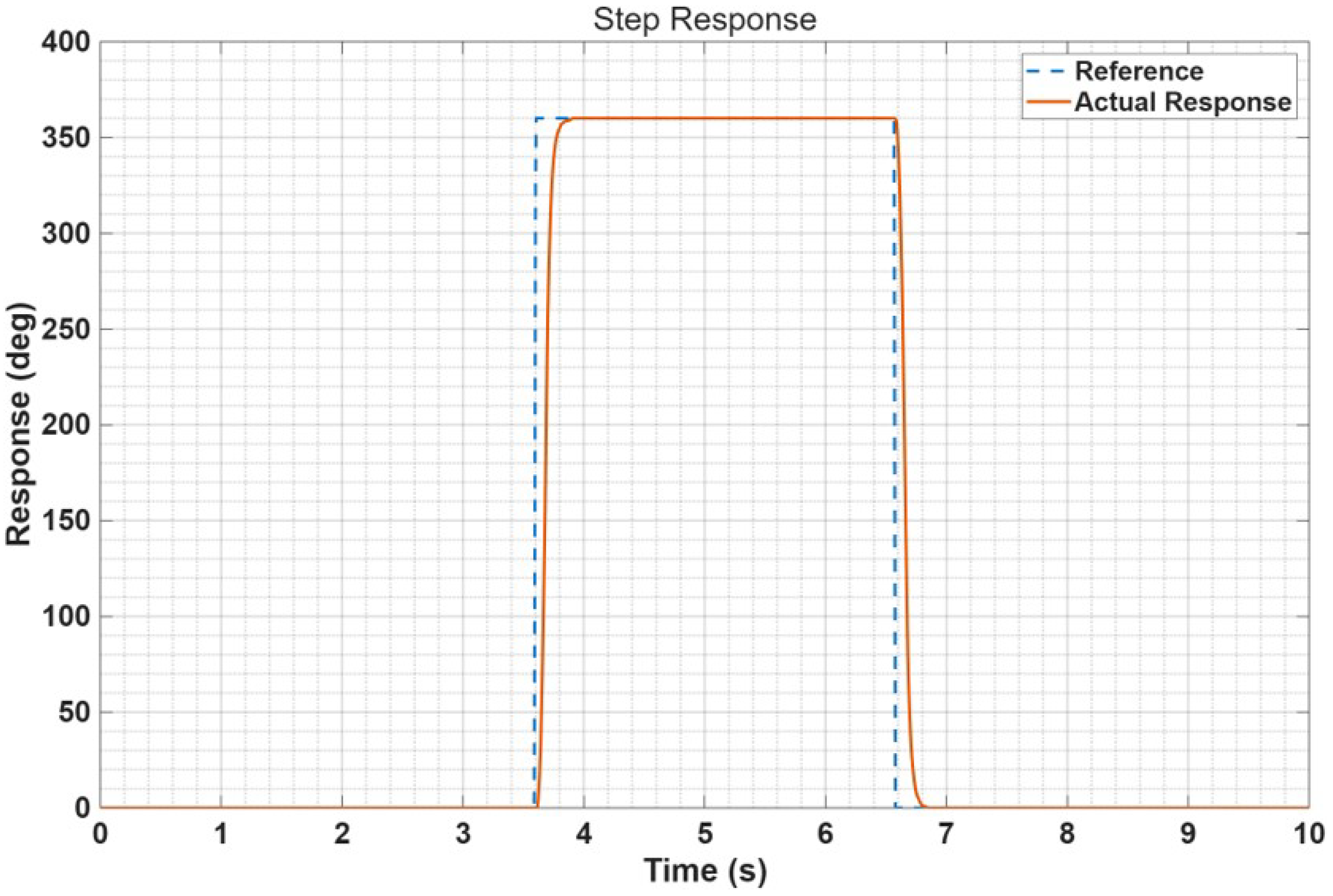
Complementing the motor design, a custom BLDC motor controller is developed featuring cascaded buck converters for multi-voltage supply, half-bridge MOSFET drivers with current sensing, and RS-422 transceiver-based BiSS-C communication with the encoder. The controller also supports CAN bus communication with a higher-level control system, facilitating integration into robotic platforms. A closed-loop PID position control algorithm is implemented at a 1 kHz update rate to evaluate the system’s dynamic performance. The experimental validation of the fabricated motor demonstrates its capability to accurately track commanded step inputs with short settling time and negligible steady-state error. These results confirm that the proposed approach successfully combines additive manufacturing flexibility with enhanced electromagnetic performance and precise sensing to produce a compact and practical actuator solution.
The contributions of this paper are summarized as follows:
Development of a hollow-shaft rotor fabricated via additive manufacturing and integrated with NdFeB permanent magnets to reduce inertia and enable through- axis applications;
Proposal of a hybrid stator design incorporating 3D-printed structures reinforced with thin nickel laminations to improve magnetic flux density while maintaining manufacturability;
Implementation of an integrated sensing system, consisting of Hall-effect sensors and a BiSS-C absolute encoder, to provide both commutation signals and high-resolution angular feedback;
Design of a custom BLDC motor controller with cascaded DC–DC converters, half-bridge MOSFET drivers, and CAN communication, enabling reliable closed-loop position control;
Experimental validation through step-response testing, demonstrating fast dynamic response, negligible steady-state error, and suitability for robotic actuation.
The paper is organized as follows.
Section 2 provides the development of the 3D-printed BLDC motor, including details of the rotor, stator, and Hall sensor. The development of the BLDC motor controller is described in
Section 3, and experimental results are presented in
Section 4. Finally, discussion and conclusions are described in
Section 5 and
Section 6, respectively.
3. BLDC Motor Controller
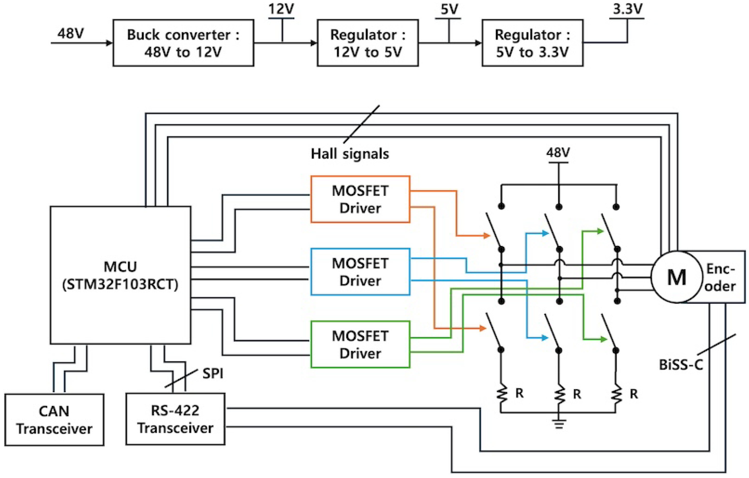
Figure 10 illustrates the block diagram of the BLDC motor controller. The power supply unit of the controller receives an external 48 V DC input, which is step-down converted sequentially to 12 V, 5 V, and finally 3.3 V through cascaded DC–DC converters. The 12 V output is used to drive the MOSFET driver circuits, the 5 V output supplies power to the Hall sensors and the absolute encoder, and the 3.3 V output is dedicated to powering the MCU.
For motor actuation, six N-channel MOSFETs are employed to configure a three-phase H-bridge topology. The switching of the high-side and low-side MOSFETs is controlled by driver ICs. Specifically, three half-bridge MOSFET driver ICs are utilized, each responsible for one phase of the BLDC motor.
The absolute encoder operates with the BiSS-C communication protocol. When the clock signal is provided to the encoder, it responds with the absolute angular position data. Since the MCU does not natively support BiSS-C communication, SPI is employed to generate the clock and receive the encoder data. Furthermore, because BiSS-C signals are transmitted as differential pairs (clock and data), RS-422 transceiver ICs are used to convert the MCU’s single-ended SPI signals into differential signals compatible with the encoder.
For communication with the higher-level controller, a CAN bus interface is adopted. To implement this functionality, the MCU interfaces with an external CAN transceiver IC, enabling reliable high-speed communication in industrial environments.
3.1. Buck Converter Design
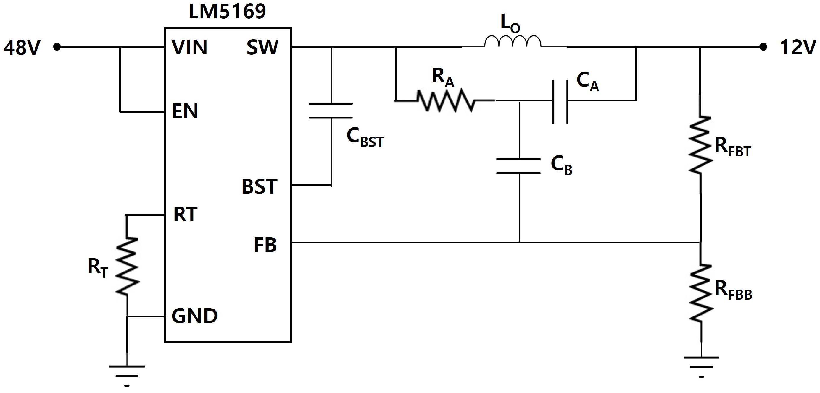
For the DC–DC step-down conversion from 48 V to 12 V, a buck converter was designed using the LM5169 controller IC. This device is a synchronous buck regulator optimized for high-voltage applications, and it was selected for its wide input voltage range and robust control scheme. To minimize output ripple and enhance stability, the circuit was configured as shown in
Figure 11. The design employs a feedback compensation network consisting of resistors
and capacitors
, along with a series resistor
. This configuration follows the recommended Type-III compensation scheme [
10] to ensure proper loop response while maintaining low output voltage ripple.
3.2. Half-Bridge Driver Design
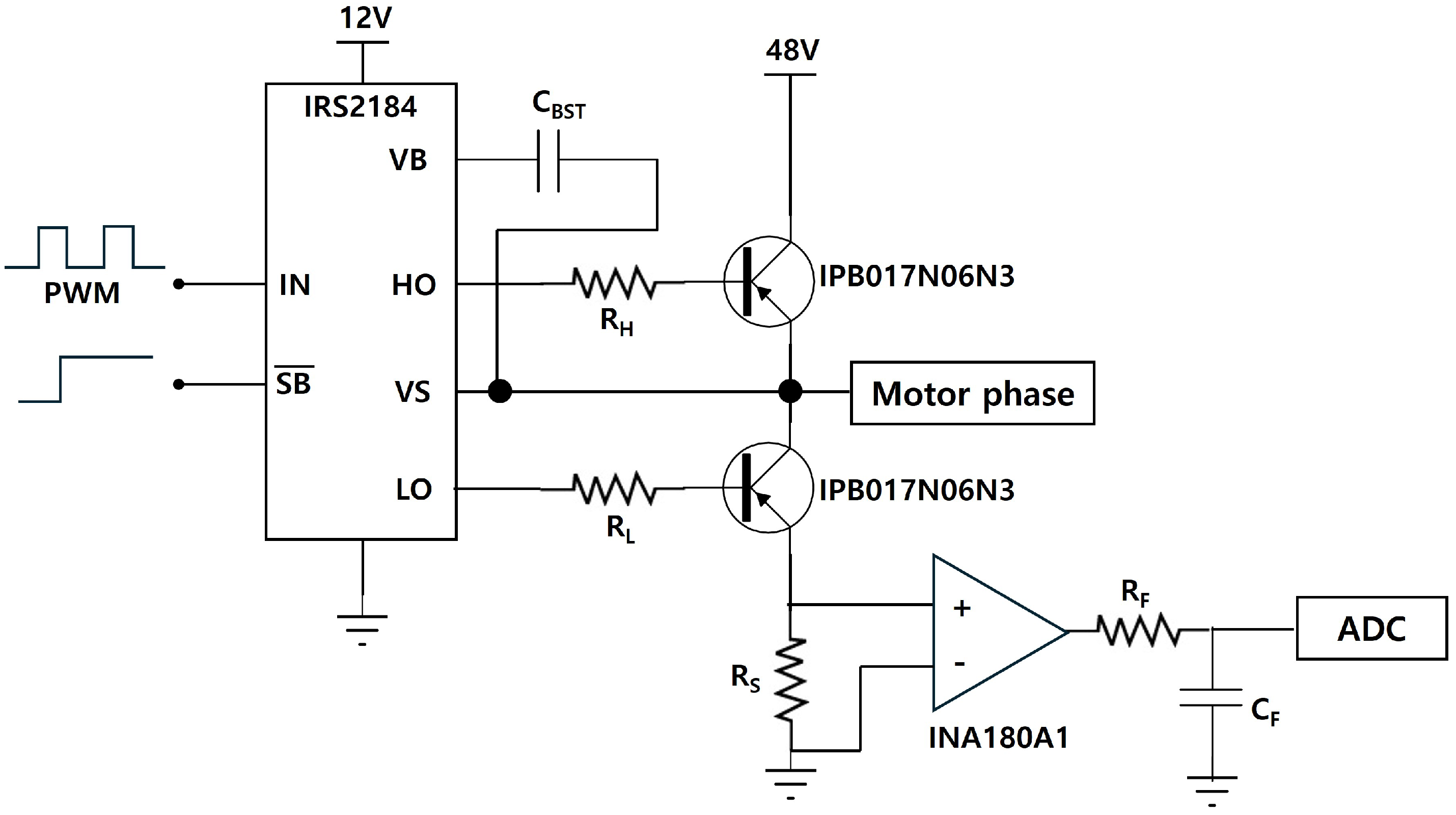
The circuit for driving each motor phase was based on a half-bridge topology, as illustrated in
Figure 12. This design used IPB017N06N3 N-channel MOSFETs for the power switching stage. An IRS2184 gate driver IC was employed to control the high-side and low-side MOSFETs. This driver IC received a PWM signal from the MCU and provided the necessary voltage and current to rapidly switch the MOSFET gates, minimizing switching losses. For phase current measurement, a low-side sensing method was implemented. A 0.005
, 2 W shunt resistor (
) was placed between the source of the low-side MOSFET and ground. The voltage drop across this resistor, which was directly proportional to the motor phase current, was detected and amplified by an INA180A1 current sense amplifier. The output signal from the amplifier was then conditioned by a low-pass filter to remove high-frequency noise before being fed into an ADC pin on the MCU for closed-loop control and monitoring.
3.3. PCB Prototype Design
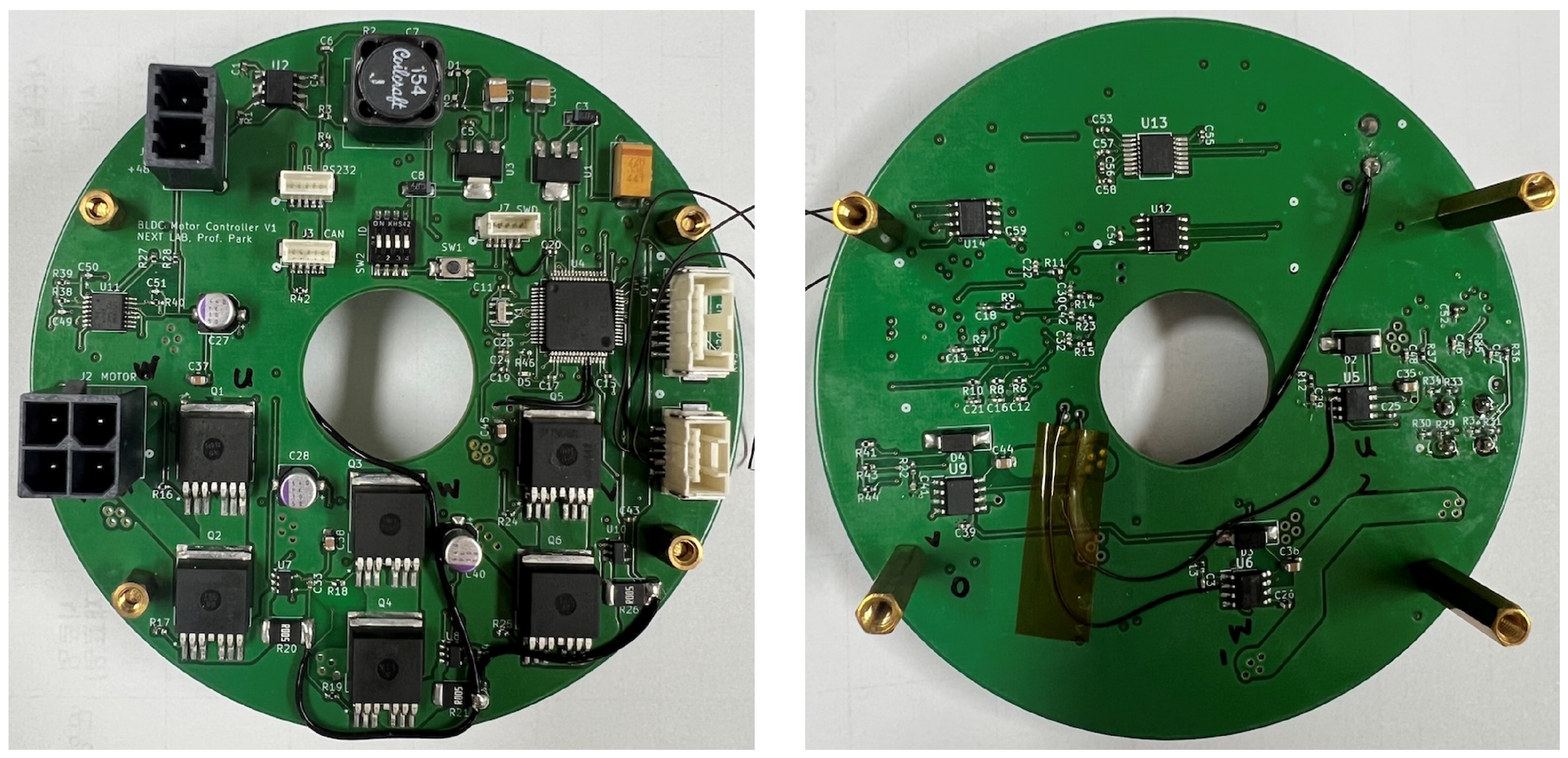
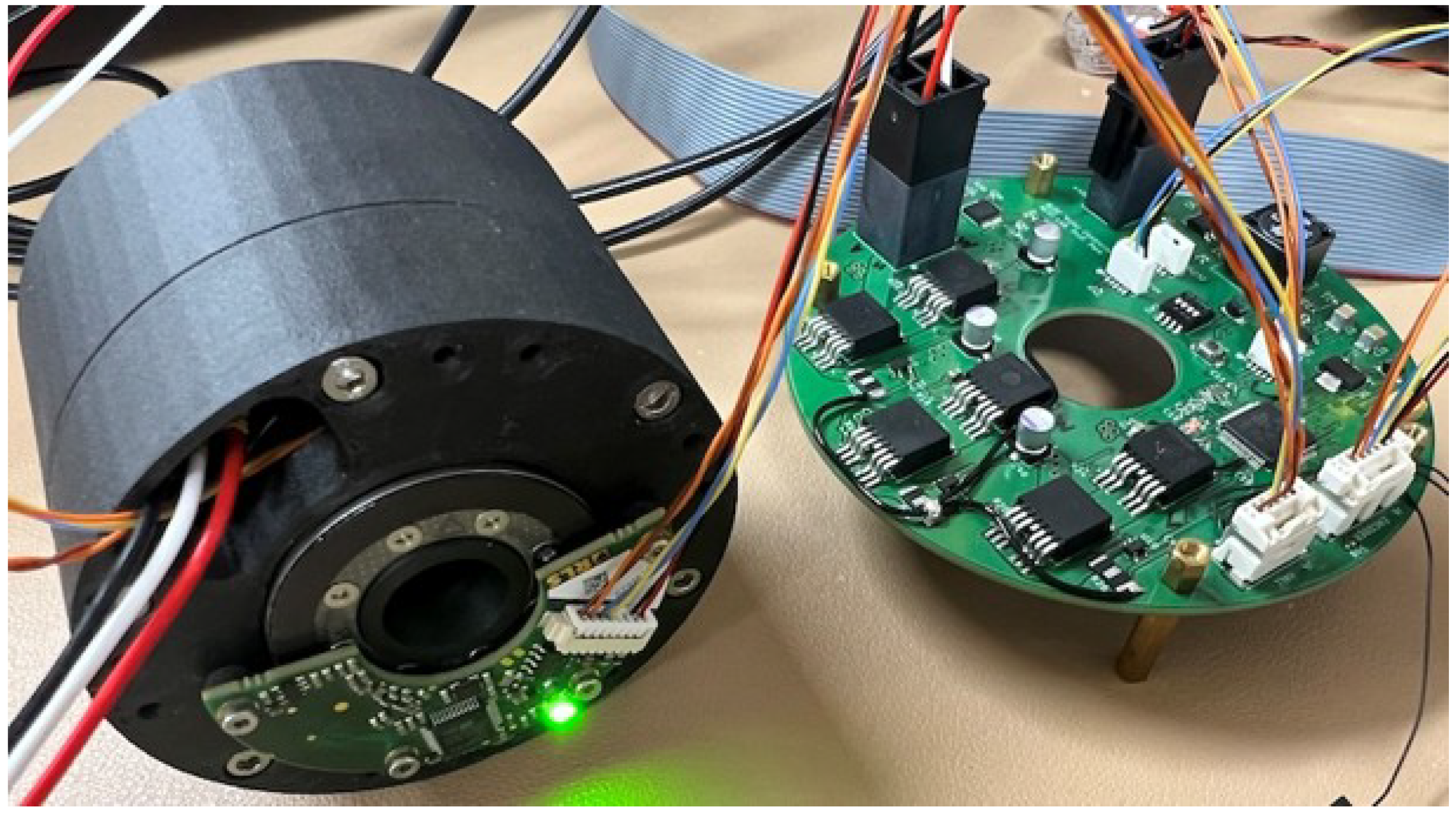
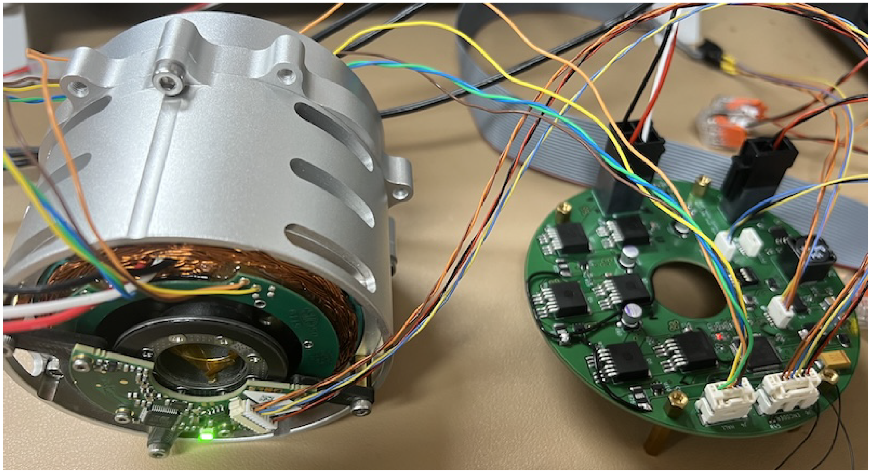
The motor controller board was custom-fabricated to align with the motor’s hollow-shaft design, resulting in a donut-shaped PCB with a central opening, as shown in
Figure 13. The current prototype version was intentionally designed to be larger than the motor itself. This is done to facilitate circuit verification and motor testing by incorporating connectors for the power supply, the three motor phases, and the Hall sensor and encoder signals. This approach follows a two-stage development strategy. The primary objective of this initial, larger version is to thoroughly validate the circuit design and complete comprehensive motor performance tests. Future iterations will focus on miniaturization. The ultimate goal is to develop a fully integrated actuator by mounting a smaller version of this controller board directly onto the rear of the BLDC motor.
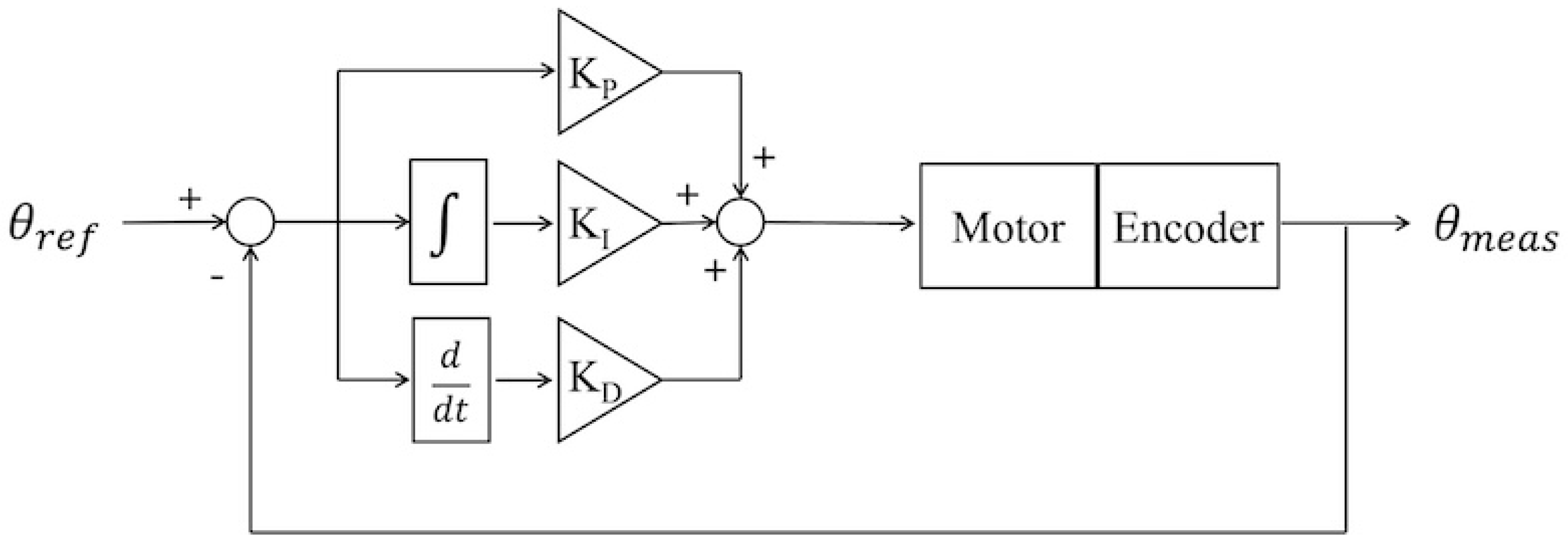
A PID control loop for position control, as shown in
Figure 14, was implemented on the controller. The PID controller was computed based on the position error, which was the difference between the reference position
and the measured position
from the encoder.
and
are expressed in encoder pulses, and the number of pulses per revolution is 524,288, corresponding to a 19-bit encoder resolution. The PID gains were tuned through a trial-and-error process to achieve a balance between responsiveness and no overshoot. They are shown in Equation (
3), where
and
are the proportional, integral, and derivative gains, respectively. The position control loop operates at a control frequency of 1 kHz.
5. Discussion
Through a trial-and-error process, the rotor and stator designs were progressively improved.
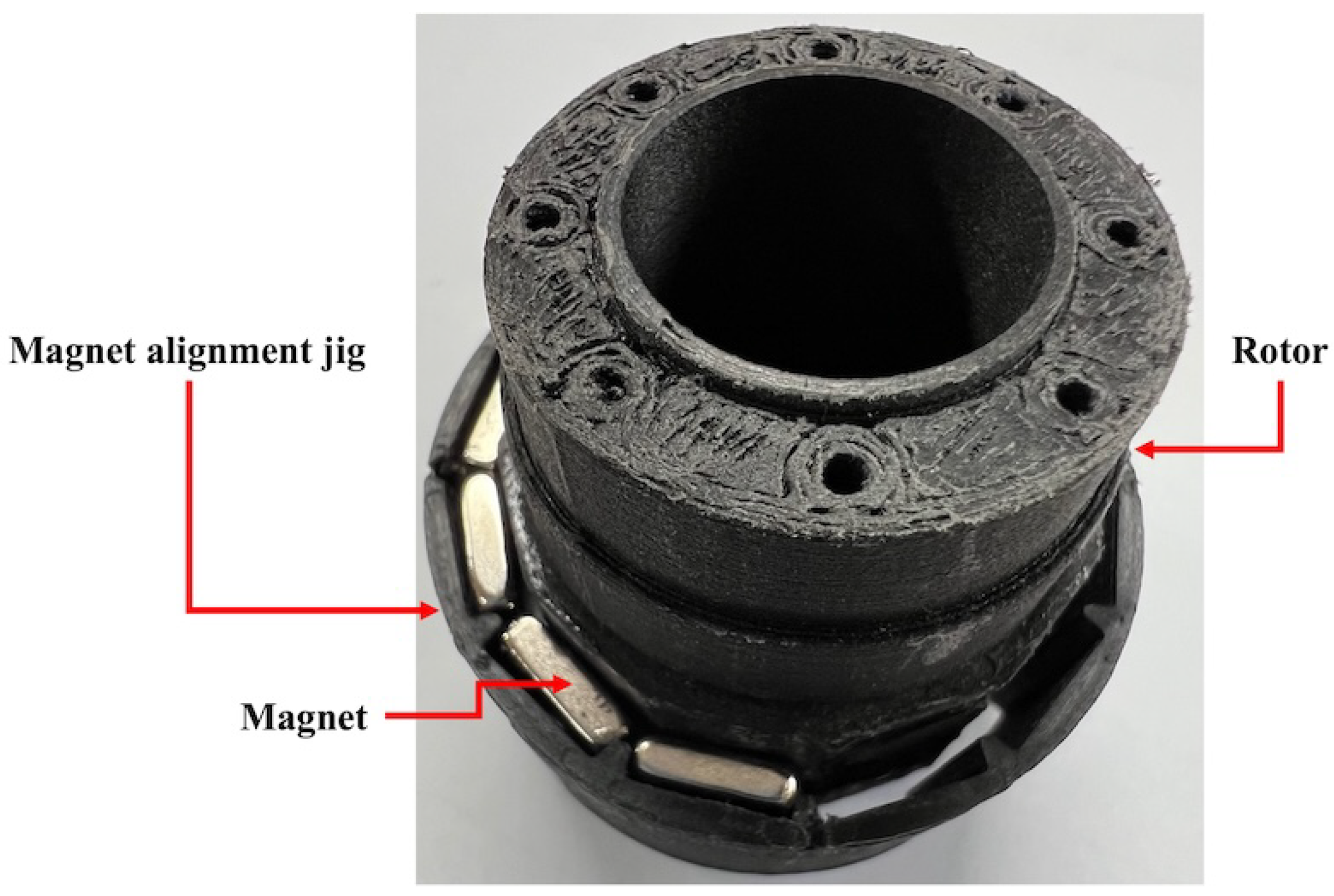
Figure 21 illustrates the early design of the rotor. In this configuration, the absence of partitions between adjacent magnets caused them to adhere to one another during assembly, necessitating the use of a dedicated magnet alignment jig. In contrast, the current rotor design shown in
Figure 3 incorporates partitions between magnets, thereby eliminating the need for such a jig during magnet placement.
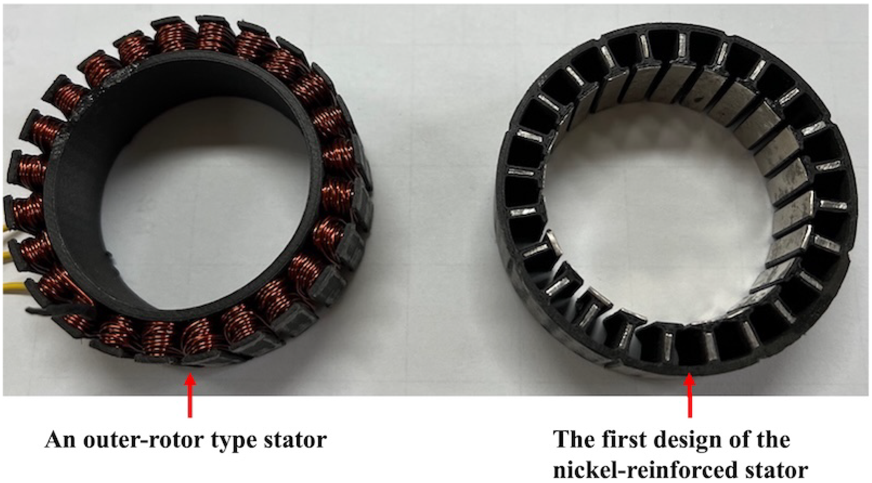
Figure 22 presents the early designs of the stator. The left shows an outer-rotor-type stator specifically designed to facilitate manual coil winding. The right depicts the first nickel-reinforced stator. However, in this early design, the thin nickel plates attached to the inner surfaces of the stator teeth frequently detached, representing a major drawback of the configuration.
During the continuous operation of the fabricated BLDC motor, a noticeable increase in the housing temperature is observed. The observed temperature of the housing is 64.3 °C after about 30 min of continuous operation. However, the material used for 3D printing, Onyx®, has a maximum operating temperature of 145 °C [
11]. Unlike conventional motors, which are typically made of metal and thus benefit from favorable thermal conductivity, the 3D-printed BLDC motor relies on non-metallic components, making it less efficient in dissipating heat. To address this limitation, design modifications such as incorporating ventilation holes into the motor housing will be implemented in the next fabrication cycle. Furthermore, the motor will be coupled with a reduction gearbox to conduct realistic load tests. In this context, robust PID control strategies applicable to nonlinear systems will be considered, with related approaches discussed by Skrjanc et al. [
12] and Wen et al. [
13]. Finally, to consider BLDC motors without Hall sensors, additional circuitry will be integrated into the controller to enable sensorless control, with reference to the approach discussed by Xu et al. [
14], and the firmware will be updated accordingly.
6. Conclusions
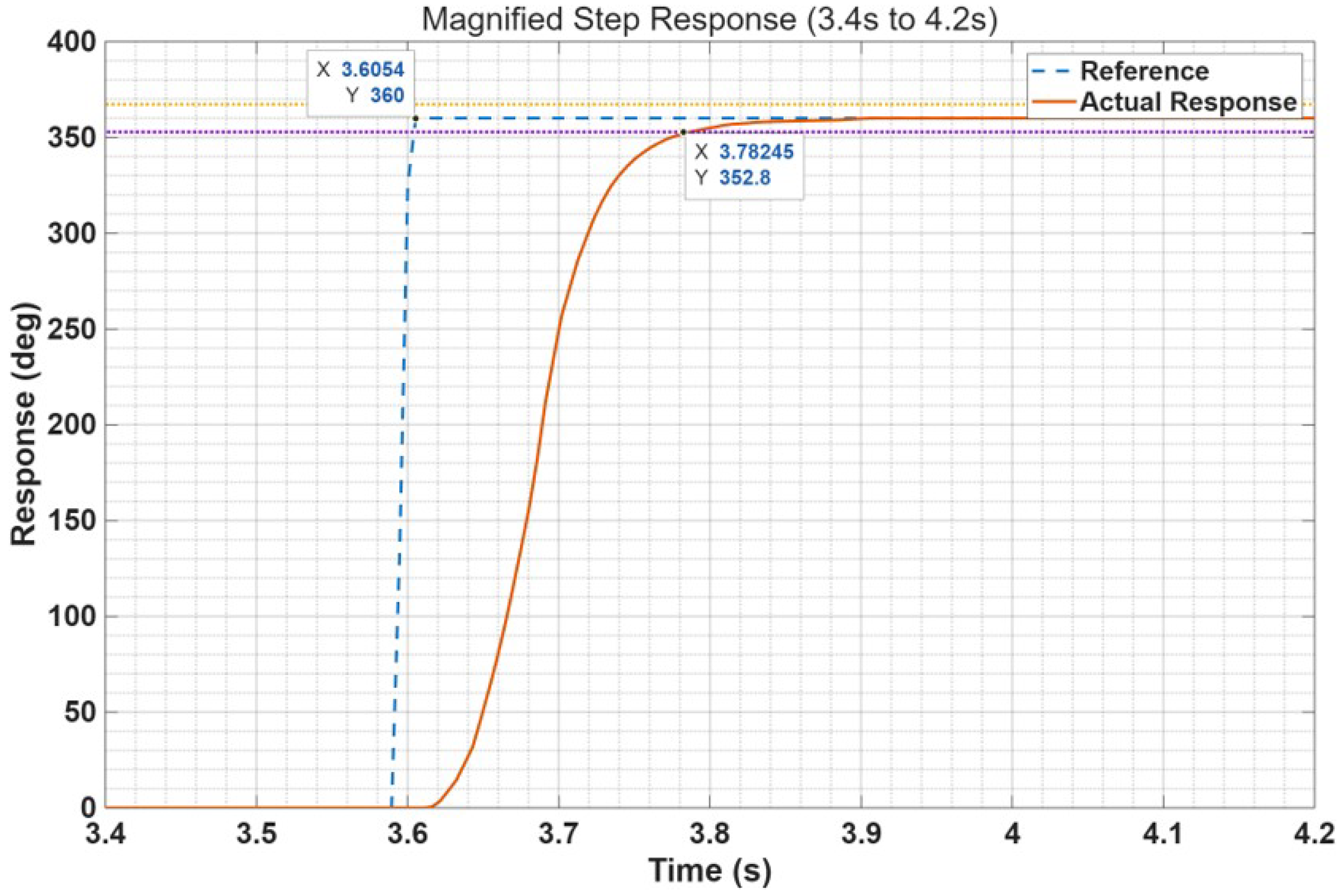
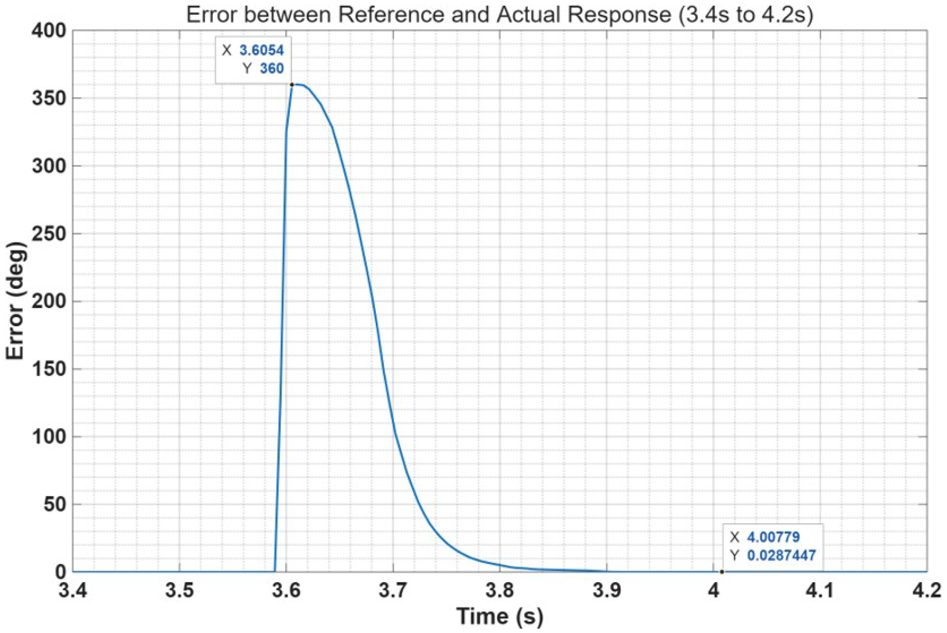
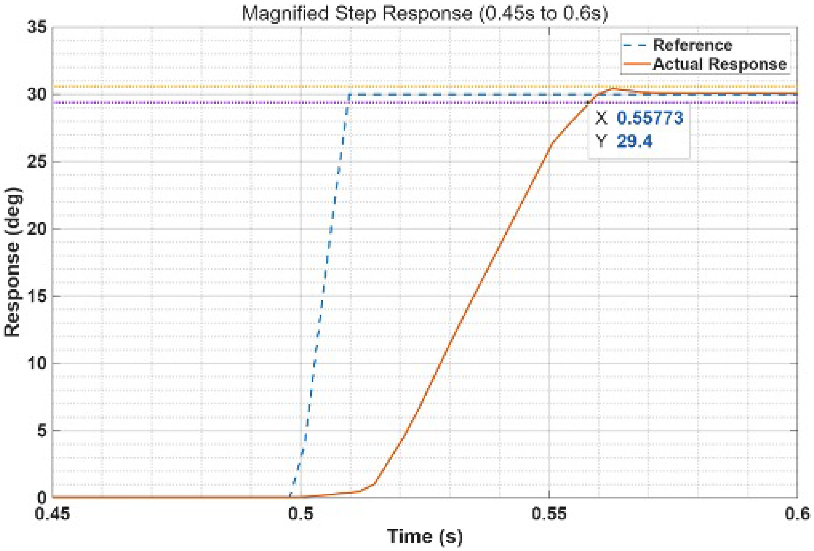
In this work, a 3D-printed BLDC motor with a hollow-shaft rotor and a nickel-reinforced stator was developed together with an integrated sensing and control system. The hybrid approach combined the design flexibility of additive manufacturing with improved electromagnetic performance through thin nickel laminations, while the custom controller enabled reliable operation with Hall sensors, an absolute encoder, and CAN communication. Experimental validation confirmed the effectiveness of the proposed design. The motor exhibited stable step responses, with a short settling time of 0.18 s and negligible steady-state error, demonstrating that the system can accurately track position commands under closed-loop control. These results verify that the presented actuator design can meet the performance requirements of robotics and precision motion applications.
Future work will focus on the further miniaturization of the motor controller, the optimization of winding and cooling strategies, and extended testing under practical load conditions. By advancing toward fully integrated actuator modules, the proposed design has the potential to contribute to the development of next-generation robotic systems requiring lightweight, customizable, and high-performance BLDC motors.
