Article

Safety-Critical End-Effector Formation Control for Planar Underactuated Manipulators

1
School of Automation, Southeast University, Nanjing 210096, China
2
Key Laboratory of Measurement and Control of Complex Systems of Engineering (Southeast University), Ministry of Education, Nanjing 210096, China
3
Institute of Intelligent Unmanned Systems, Southeast University, Nanjing 210096, China
*
Author to whom correspondence should be addressed.
Actuators 2025, 14(10), 475; https://doi.org/10.3390/act14100475
Submission received: 28 July 2025 / Revised: 22 September 2025 / Accepted: 23 September 2025 / Published: 28 September 2025
(This article belongs to the Section Control Systems)

Abstract

While networked multi-agent systems have been widely explored, the challenges introduced by underactuation still impede safety-critical cooperative control of multiple underactuated manipulators. This paper introduces a distributed framework for end-effector formation control and obstacle avoidance in planar n-link manipulators with a passive first joint and active remaining joints—termed PAn−1 manipulators. By exploiting the integrability of each PAn−1 manipulator’s second-order nonholonomic constraint, we reformulate the dynamics into a cascaded structure and derive a reduced-order model driven solely by active joint velocities. Building on this reduced-order model, we design safety-critical distributed formation control laws for the reduced-order dynamics, which serve as the manipulators’ desired active joint velocities. Then, we employ the backstepping method to obtain control inputs for the full-order dynamics. To guarantee safety, we treat backstepping tracking errors as matched disturbances and address them within a robust control barrier function framework. Numerical simulations and comparative studies confirm the effectiveness of the proposed approach.

1. Introduction

Formation control for networked multi-agent systems has attracted considerable attention over the past decade [1,2,3,4], driven by applications ranging from unmanned aerial vehicles to autonomous surface vessels. Early works focused primarily on simple agent models—such as single- or double-integrator kinematic points—where each agent’s control input directly influences the state variables that define the collective formation. To bridge the gap between these results and the more complex dynamics, Wu et al. [5] introduced the distributed end-effector formation control for multiple cooperative manipulators, in which the formation is defined by end-effector positions whereas the control inputs act at the joint level.
Despite its promising contributions, the approach proposed in Ref. [5] overlooks two realistic and critical challenges inherent to multi-agent systems. First, actuator faults represent a significant issue, particularly in multi-agent systems where such faults occur frequently and pose substantial risks. These faults can severely compromise system performance; in extreme cases, manipulators may lose control authority over one or more joints, thus becoming underactuated—meaning the manipulator has fewer independent control inputs than degrees of freedom. The presence of the underactuated manipulators in the group will make the method in [5] inapplicable. Second, formation control is often applied to multi-manipulator teams performing complex tasks in cluttered, obstacle-rich environments—such as hazardous-material handling or robotic surgery. Therefore, guaranteeing collision-free coordination at all times is vital for safe operation.
Several studies have addressed actuator faults [6,7,8] and collision avoidance [9,10] within multi-agent systems. However, these works mainly deal with milder actuator faults, typically modeled as multiplicative or additive perturbations of available inputs, where all degrees of freedom remain controllable. By contrast, this study focuses on severe joint faults that disable torque production at some joints, removing input channels and leading to structural underactuation rather than input deviations. In our earlier work [11,12], we established distributed end-effector formation control for multiple underactuated planar manipulators. Nonetheless, that investigation was limited to two-link manipulators and did not account for obstacle avoidance. Recently, control barrier functions (CBFs) have emerged as powerful tools for enforcing safety constraints in real time [13,14,15]. However, constructing suitable CBFs for high-order dynamical systems, particularly for underactuated manipulators, remains challenging due to issues related to the relative degree of the functions. For fully actuated manipulators, a standard approach is to transform the dynamics into a cascaded form and then construct CBFs via the reduced-order model [15,16]. However, underactuated manipulators do not have independent actuation at all joints, which leads to force coupling between active and passive joints. This coupling gives rise to second-order nonholonomic constraints—second-order differential equations in the joint angles—within the system dynamics. Consequently, the dynamics of underactuated manipulators generally cannot be transformed into a cascaded form composed of multiple first-order subsystems, which prevents the direct extension of the aforementioned CBF-based methods.
Motivated by these gaps, this study investigates the safety-critical end-effector formation control of a team of planar n-link underactuated manipulators under explicit safety constraints, simultaneously addressing underactuation and obstacle avoidance. In each manipulator, the first joint is passive and the remaining n − 1 joints are actuated, a configuration referred to as the PAn−1 manipulator. Our main contributions are as follows.
As noted earlier, a key challenge is that the safety constraint on the end-effector position has relative degree greater than one with respect to the torque inputs, resulting in a relative-degree mismatch for CBF-based synthesis. To cope with this, we aim to reformulate the underactuated manipulator dynamics into a cascaded form of first-order subsystems and derive a reduced-order model for each agent. However, the dynamics coupling, manifested as second-order nonholonomic constraints, prevents a direct transformation, unlike in fully actuated systems. In this study, we exploit the integrability of the second-order nonholonomic constraint of the PAn−1 manipulator [17,18]. By integrating the second-order constraint on the joint accelerations into a first-order kinematic constraint, we decouple the second-order and first-order terms present in the dynamics, thereby reformulating the system into a cascaded form.
On the resulting cascaded representation, we can synthesize a CBF-based controller on the reduced-order subsystem to generate ideal active-joint velocity commands that satisfy safety constraints. Backstepping [19,20,21] is then applied to the upper-level dynamics to design a tracking controller that compels the upper-level output to follow the prescribed velocities. However, directly applying a standard backstepping procedure inevitably introduces tracking errors, which could lead to violations of prescribed safety constraints. To mitigate this risk, we model the tracking error as a matched disturbance and employ the robust CBF (RCBF) framework proposed in [15]. Specifically, we conservatively shrink the original safe set by an amount proportional to the worst-case disturbance magnitude, thereby ensuring the system state remains strictly within the true safe region despite the presence of disturbances. Simulation results from two numerical case studies confirm the effectiveness of the proposed control scheme.
The remainder of this paper is organized as follows. In Section 2, we review the necessary background, including the dynamics model of the discussed underactuated manipulators and CBFs for obstacle avoidance. Section 3 formulates the problem statement. In Section 4, we present our main results: the distributed formation control design via cascaded reduction and the robust CBF-based obstacle-avoidance scheme. Section 5 provides numerical simulations and comparative studies. Finally, Section 6 concludes the paper and discusses potential research directions in the future.

2. Preliminaries

In this section, we briefly introduce the notation and review the essential background, including the dynamic model of the discussed underactuated PAn−1 manipulators and the CBF-based method for obstacle avoidance.
Notation: Define col ( p 1 , , p N ) = p 1 T , , p N T T as the stacked vector of the column vectors p i , i = { 1 , , N } ; define blockdiag ( M 1 , , M N ) as the block-diagonal matrix whose i-th diagonal block is M i , { i = 1 , , N } . Finally, let [ M ] α β denote the entry of matrix M in its α th row and β th column.

2.1. Dynamics of Underactuated Manipulators

Consider a group of robotic manipulators, each with n links, operating in a gravity-free X Y plane (see Figure 1). Each manipulator’s first joint is unactuated (e.g., due to actuator fault), while the remaining n − 1 joints are actuated. For the α -th link ( α { 1 , , n } ) of manipulator i { 1 , , N } , let m i , α denote its mass, I i , α its moment of inertia about its center of mass (CoM), L i , α its length, and l i , α the distance from joint α to its CoM. Denote the global frame by ΣW and the local frame of manipulator i by Σi, with their relative rotation given by ϕ i . Let q i , α , α { 1 , , n } denote the generalized coordinate (e.g., joint angle) and q ˙ i , α , q ¨ i , α its first and second derivatives; denote the corresponding link angle relative to the vertical axis of Σi as θ i , α = γ = 1 α q i , γ . Then, define the generalized coordinate vector q i = [ q i , 1 , , q i , n ] T R n and the active-joint sub-vector q i a = [ q i , 2 , , q i , n ] T R n 1 . Let τ i , α be the torque at joint α , and stack these as τ i = [ τ i , 1 , , τ i , n ] T = col [ 0 , τ i a ] R n , where τ i a = [ τ i , 2 , , τ i , n ] T R n 1 contains only the nontrivial ones.
Utilizing the dynamic formulation of the n-link manipulator from [22,23], the manipulator’s motion in a two-dimensional, gravity-free plane is described by
M i q i q ¨ i + C i q i , q ˙ i q ˙ i = τ i , M i q i R n × n = S T M ¯ i S , C i q i , q ˙ i R n × n = S T C ¯ i S ,
where M i ( q i ) is the symmetric positive-definite inertia matrix, and C i ( q i , q ˙ i ) q ˙ i represents Coriolis and centrifugal forces. Specifically, the matrix S R n × n is defined as
S R n × n = 1 0 0 0 1 1 0 0 1 1 1 0 1 1 1 1 .
The elements of the matrices M ¯ i , C ¯ i R n × n at the ( α , β ) -th position are given by
M ¯ i α β = λ i , α β cos θ i , β θ i , α ,
C ¯ i α β = λ i , α β θ ˙ i , β sin θ i , β θ i , α ,
with the mechanical parameter λ i , α β defined as
λ i , α α = I i , α + m i , α l i , α 2 + L i , α 2 γ = α + 1 n m i , γ , 1 α n , λ i , α β = λ i , β α = m i , β L i , α l i , β + L i , α L i , β γ = β + 1 n m i , γ , 1 α < β n .
Here, summation terms for the case when α = n or β = n are defined to be zero.
As the simplest nontrivial case ( n = 2 ), the PA manipulator (whose base joint is passive and the second joint is active) exhibits important differences in its dynamic behavior compared to the manipulators with n 3 , and is therefore discussed separately. Derivable directly from the general n-link formulation, the PA manipulator’s dynamics are given by
M i q i q ¨ i + C i q i , q ˙ i q i = τ i ,
where q i = [ q i , 1 , q i , 2 ] T and τ i = [ 0 , τ i , 2 ] T . The matrices M i ( q i ) , C i ( q i , q ˙ i ) are, respectively, given by
M i q i = λ i , 11 + λ i , 22 + 2 λ i , 12 cos q i , 2 λ i , 22 + λ i , 12 cos q i , 2 λ i , 22 + λ i , 12 cos q i , 2 λ i , 22 ,
C i ( q i , q ˙ i ) = λ i , 12 q ˙ i , 2 q ˙ i , 1 q ˙ i , 2 q ˙ i , 1 0 sin q i , 2 ,
where λ i , 11 = m i , 1 l i , 1 2 + m i , 2 L i , 1 2 + I i , 1 , λ i , 22 = m i , 2 l i , 2 2 + I i , 2 , and λ i , 12 = m i , 2 L i , 1 l i , 2 .

2.2. Control Barrier Functions

Define the state vector for the manipulator i as x i = col ( q i , q ˙ i ) R 2 n . The dynamics, Equations (1) and (6), can be rewritten as
x ˙ i = f i ( x i ) + g i ( x i ) u i ,
where u i ( t ) R n 1 denotes the active control input, and f i : R 2 n R 2 n , g i : R 2 n R 2 n × ( n 1 ) are C differentiable functions.
To enforce safety constraints on the system, Equation (9), we employ a CBF-based safety-critical control framework. Define the safe set C as
C = { x i R 2 n : h i ( x i ) 0 } ,
where h i ( x i ) is a continuously differentiable function. The system is safe with respect to C if C is forward invariant. In other words, whenever the state starts in C , it remains in C for all time (see, e.g., ([15], Definition 1)). The function h i ( x i ) is called a CBF for the system, Equation (9), if there exists an extended class- K function κ ( · ) such that
sup u i L f i h i ( x i ) + L g i h i ( x i ) u i > κ h i ( x i )
holds for all x i (see, e.g., ([15], Definition 5)). Intuitively, this condition implies that at any state x i , there exists some control input u i that prevents h i ( x i ) from decreasing too rapidly (or violating h i < 0 ). As shown in ([15], Lemma 2), when the input u i is unbounded, the condition in Equation (11) reduces to, for all x i ,
L g i h i ( x i ) = 0 L f i h i ( x i ) > κ h i ( x i ) .
As noted in [15], the strict inequalities in Equations (11) and (12) guarantee the Lipschitz continuity of the CBF-based controller. In practice, one imposes the CBF constraint in a simplified linear inequality form
L f i h i ( x i ) + L g i h i ( x i ) u i + κ h i ( x i ) 0
for all times. Any Lipschitz continuous control law satisfying this will render the safe set C forward invariant ([15], Theorem 4). In other words, if h i ( x i ) is initially nonnegative, it remains nonnegative for all future time, which guarantees the enforced safety constraint is never violated. Note that the constraint in Equation (13) is affine in the control input u i , which makes it convenient to incorporate into a real-time QP. However, constructing suitable CBFs for high-order dynamical systems, particularly for underactuated manipulators, can be nontrivial, as challenges often arise due to issues related to the relative degree of the functions.

3. Problem Formulation

This paper addresses the safety-critical end-effector formation control for a team of PAn−1 manipulators, ensuring that their end-effectors collectively achieve a prescribed geometric formation while simultaneously avoiding obstacles in the workspace. This section formulates the control problem.

3.1. Formation Shape Specification

The end-effector position p i end of the i-th manipulator in the world frame ΣW is defined as
p i end ( q i ) = p i 0 + P i ( q i ) ,
where p i 0 R 2 is the base position and
P i ( q i ) = P i , 1 ( q i ) , P i , 2 ( q i ) T = α = 1 n L i , α sin θ i , α + ϕ i , α = 1 n L i , α cos θ i , α + ϕ i T ,
Here, θ i , α = γ = 1 α q i , γ and ϕ i is the orientation offset.
Now, introduce an undirected graph G = ( V , E ) to describe the topological connections among the manipulators’ end-effectors. Each vertex i V corresponds to the end-effector of the i-th manipulator, and an edge ( i , j ) E implies a neighbor relationship between manipulators i and j. The stacked position vector of all end-effectors is denoted as p end R 2 N = col ( p 1 end , . . . , p N end ) . Using the incidence matrix B R N × | E | of graph G , define the relative displacement vector as
z = col ( z 1 , . . . , z | E | ) = B ¯ T p end , where B ¯ = B I 2 .
Here, ⊗ denotes the Kronecker product. Each element z k = p i end p j end of the stacked vector z corresponds to edge ( i , j ) . Given a desired formation shape specified by the desired distance vector d R | E | , there exists a reference position p of p end such that for every k, we have z k ( p ) = d k . The desired formation shape set is thus defined as [11]
S = { p end : p end = ( I N R ) p + 1 N b , ; R SO ( 2 ) , b R 2 } ,
where I N denotes the N × N identity matrix, and 1 N denotes the N-dimensional vector whose entries are all ones. Each manipulator’s end-effector workspace is denoted by W i , and the collaborative workspace of all manipulators is W = W 1 × × W N . Consequently, the realizable formation set within the workspace is defined as S W = S W .

3.2. Obstacle Avoidance Constraints

For operational safety, we require each manipulator’s end-effector to remain outside every obstacle. Let O denote the set of obstacles in the manipulators’ plane, where each obstacle j O is modeled as a closed disk of radius r j > 0 centered at o j R 2 . The safety requirement can then be compactly stated as
p i end ( q i ) o j r j , i = 1 , , N , j O .
In this work, we restrict collision checks to those between end-effectors and obstacles. Although link collisions can be important in many practical settings, they can be accommodated by introducing analogous safety constraints. This simplification streamlines both problem statement and analysis. Moreover, in applications where links are shielded or kept safely away from obstacles—or where only the end-effector operates within tightly controlled hazardous zones—focusing exclusively on the end-effector is both realistic and sufficient.

3.3. Control Objectives

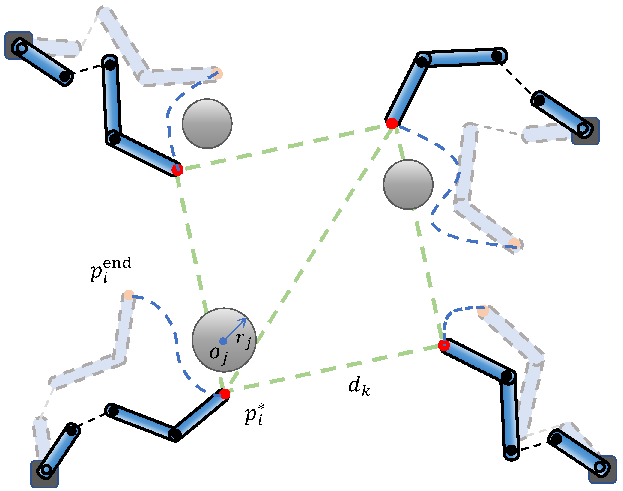
With the problem clearly structured, we specify the following two primary control objectives (see also Figure 2):
  • Formation Keeping: Develop a control strategy ensuring that the manipulators’ end-effectors converge into the feasible set S W , achieving and maintaining the desired geometric shape.
  • Obstacle Avoidance: Guarantee that the positions of all end-effectors satisfy the safety constraints in Equation (18) at all times, thus preventing collisions.

4. Main Results

In this section, we summarize our primary theoretical and methodological contributions. Section 4.1 leverages the integrability of the second-order nonholonomic constraint inherent to the planar PAn−1 manipulator to reformulate its dynamics into a cascaded form. Based on this reformulation, Section 4.2 proposes a safety-critical formation controller to ensure that both specified control objectives are achieved.

4.1. Modeling Underactuated Manipulators in the Cascaded Form

Note that the motion Equation (1) of the PAn−1 manipulator i is subject to the following second-order nonholonomic constraint
α = 1 n M i 1 α q ¨ i , α + C i 1 α q ˙ i , α = 0 ,
which, in the special case n = 2 , reduces to
[ M i ] 11 ( q i ) q ¨ i , 1 + [ M i ] 12 ( q i ) q ¨ i , 2 λ i , 12 2 q ˙ i , 1 q ˙ i , 2 + q ˙ i , 2 2 sin q i , 2 = 0 .
We now recall a lemma that will be used later.
Lemma 1 
([17,18]). Consider the PAn−1 manipulator indexed by i starts from rest, i.e., q ˙ i ( 0 ) = 0 . Then, the constraint in Equation (19) can be integrated to
α = 1 n [ M i ] 1 α ( q i ) q ˙ i , α = 0 .
In the special case n = 2 , Equation (21) simplifies to
[ M i ] 11 ( q i ) q ˙ i , 1 + [ M i ] 12 ( q i ) q ˙ i , 2 = 0 .
Remark 1. 
In the special case of n = 2 , integrating the joint velocity constraint in Equation (22) directly yields a relationship between the two joint angles, allowing us to express q i , 1 as a function of q i , 2 , i.e., q i , 1 = F ( q i , 2 ) , where the explicit form of F ( q i , 2 ) can be found in ([11], Lemma 1). As a result, its end-effector position is restricted to a curve parameterized by q i , 2 , namely p i end ( q i , 2 ) = p i 0 + P i ( F ( q i , 2 ) , q i , 2 ) . Note that the curve is uniquely determined by the mechanical parameters and the initial state of the PA manipulator. This restriction reduces the workspace of the manipulator group where PA manipulators are involved. A detailed analysis given in our previous work [11,12] shows that the proposed end-effector formation controller is applicable only when the group contains at most three PA manipulators.
Now, we are ready to model the PAn−1 manipulator i in the cascaded form using the constraint in Equation (21). Since M i is positive definite, we know [ M i ] 11 ( q i ) > 0 for all q i . Hence, from Equation (21), the passive joint velocity q ˙ i , 1 can be solved in terms of the active joint velocities q ˙ i , 2 , , q ˙ i , n .
q ˙ i , 1 = 1 [ M i ] 11 α = 2 n [ M i ] 1 α q ˙ i , α .
Defining v i = q ˙ i a , we obtain the reduced-order model of the PAn−1 manipulator from the constraint in Equation (23)
q ˙ i , 1 q ˙ i a x ˙ i 0 = 1 [ M i ] 11 col T [ M i ] 12 , , [ M i ] 1 n I n 1 g i 0 ( x i 0 ) v i x i 1 .
We now express v ˙ i by the active joint torque vector τ i a . We partition the generalized coordinate q i R n of the PAn−1 manipulator i into the passive-joint scalar q i , 1 R and the active-joint vector q i a R n 1 . Define H i ( q i , q ˙ i ) = C i ( q i , q ˙ i ) q ˙ i , and Equation (1) can be rewritten in a block form as
M i uu ( q i ) M i ua ( q i ) M i au ( q i ) M i aa ( q i ) M i ( q i ) q ¨ i , 1 q ¨ i a q ¨ i + H i u ( q i , q ˙ i ) H i a ( q i , q ˙ i ) H i ( q i , q ˙ i ) = 0 τ i a .
Here, M i uu ( q i ) = [ M i ] 11 ( q i ) R is positive, and M i aa ( q i ) R ( n 1 ) × ( n 1 ) is symmetric and positive-definite; H i u , H i a collect the Coriolis forces on the passive and active coordinates, respectively. Since the scalar M i uu ( q i ) is positive, we have
q ¨ i , 1 = 1 M i uu ( q i ) M i ua ( q i ) q ¨ i a + H i u ( q i , q ˙ i ) .
Then, substituting Equation (26) into the second equation in Equation (25) yields
M i Comb ( q i ) q ¨ i a + H i Comb ( q i , q ˙ i ) = τ i a ,
where
M i Comb ( q i ) = M i aa ( q i ) 1 M i uu ( q i ) M i au ( q i ) M i ua ( q i ) ,
H i Comb ( q i , q ˙ i ) = H i a ( q i , q ˙ i ) 1 M i uu ( q i ) M i au ( q i ) H i u ( q i , q ˙ i ) .
As the Schur complement of the symmetric positive-definite matrix M i , the matrix M i Comb is also symmetric and positive-definite [24].
Therefore, from Equation (27), we obtain
v ˙ i x ˙ i 1 = M i Comb ( q i ) 1 H i Comb ( q i , q ˙ i ) f i 1 ( x i 0 , x i 1 ) + M i Comb ( q i ) 1 g i 1 ( x i 0 ) τ i a
Note that M i Comb ( q i ) 1 H i Comb ( q i , q ˙ i ) is a function of states x i 0 and x i 1 , since, by Equation (24), q ˙ i can be expressed in terms of x i 1 . Accordingly, the PAn−1 manipulator i can be expressed in the cascaded form Equations (24) and (30), which facilitates the controller design via the standard backstepping method.
Remark 2. 
It should be noted that neither our previous studies [11,12] nor most existing research on underactuated manipulator control [23,25] transformed the manipulator into a cascaded form. In this study, however, we introduce such a cascaded-form transformation explicitly to fulfill the requirements of the CBF-based safety-critical controller design. As discussed in the Introduction, this cascaded-form transformation is not universally applicable to all underactuated manipulators. Specifically, the transformation here leverages the integrability of the second-order nonholonomic constraint, which is a distinct property of the PAn1 manipulator.

4.2. Safety-Critical Controller for End-Effector Formation

In what follows, we extend the distributed end-effector formation controller proposed in [11] for the two-link case to the general n-link manipulator and incorporate obstacle avoidance based on the obtained cascaded-form dynamics.

4.2.1. End-Effector Formation Control for Reduced-Order Model

Let d R | E | denote the desired distance vector for an infinitesimally rigid formation (see [26] for its definition). The error on each edge E k is then defined by
e k = z k 2 d k 2 ,
and collect them into e = col ( e 1 , , e | E | ) . Then, define the formation potential function
V ( e ) = K P 2 k = 1 | E | e k 2 .
Since
z k p i end = [ B ] i k , D k ( z k ) = e k z k = 2 z k ,
it follows that the gradient of V ( e ) with respect to p i end is
K P e ^ i = V ( e ) p i end = K P k = 1 | E | [ B ] i k D k ( z k ) e k .
Collecting all e ^ i into the vector e ^ = col ( e ^ 1 , , e ^ N ) R 2 N , and letting D ( z ) R 2 | E | × | E | be the block-diagonal matrix with blocks D k ( z k ) , we may therefore rewrite Equation (34) in the compact form as
K P e ^ = V ( e ) p end = K P B ¯ D ( z ) e .
Note that for the infinitesimally rigid framework ( G , p ) , the matrix D ( z ) T B ¯ T B ¯ D ( z ) is positive definite at p [27].
Next, for the reduced-order model, Equation (24), of each PAn−1 manipulator i, we design the desired active joint velocity v i to ensure that the prescribed formation shape can be achieved. Before proceeding, we state the following assumption.
Assumption 1. 
There exists a constant μ > 0 and a neighborhood
S W μ = p end R 2 N : e < μ
around S W such that, for each PAn−1 manipulator i ( n 3 ), its kinematic Jacobian matrix J i ( q i ) remains full row rank for every p end S W μ .
Note that J i ( q i ) = p i end q i R 2 × n is the standard Jacobian matrix of an n-link planar manipulator. Denote J ¯ i ( q i ) R 2 × ( n 1 ) as the Jacobian of the end-effector position with respect to the n − 1 active joint angles, which is specifically defined for PAn−1 manipulators:
J ¯ i ( q i ) = J i ( q i ) 1 [ M i ] 11 col T [ M i ] 12 , , [ M i ] 1 n I n 1 .
Clearly, when n 3 , the assumption that J i ( q i ) has full row rank implies that the matrix J ¯ i ( q i ) also has full row rank, owing to the presence of the block I n 1 in the multiplied matrix. The following remarks further clarify this assumption.
Remark 3. 
Assumption 1 is introduced to ensure that the manipulators avoid singular points during the control process. This requirement is standard in the end-effector control (see, e.g., ([28], Property 5), ([29], Theorem 1), [24]) and is not restrictive. Although the existence of S W μ is required, its size is not critical; it suffices that the reference point is non-singular. By continuity, a singularity-free neighborhood S W μ always exists if the reference point p S W is chosen such that q i is non-singular for all i. Since singular configurations occupy only a negligible subset of the joint space, it is always possible to select q i such that the manipulator operates away from singularities.
Remark 4. 
When n = 2 , J ¯ i ( q i ) reduces to the 2 × 1 vector J ¯ i ( q i ) = J ¯ i , 1 ( q i ) , J ¯ i , 2 ( q i ) T , and therefore cannot be full row rank. In this case, as shown in our previous work [11], we do not require J i ( q i ) to remain full row rank; instead, we require that both components of J ¯ i ( q i ) are non-zero, i.e.,
J ¯ i , 1 ( q i ) 0 and J ¯ i , 2 ( q i ) 0 .
For a detailed analysis of this special case, see [11].
Theorem 1. 
Consider the reduced-order model, Equation (24), of the PAn−1 manipulators. Under Assumption 1, the end-effector formation keeping problem can be solved locally by the distributed control law
v i = v i 0 = K P 1 [ M i ] 11 col T [ M i ] 12 , , [ M i ] 1 n I n 1 T J i T ( q i ) e ^ i ,
where K P > 0 is the control gain, e ^ i is defined in Equation (34), and M i denotes the inertia matrix associated with the dynamics of manipulator i, whose expression is given in Equation (1).
Proof. 
Consider the Lyapunov function as U 1 = V ( e ) defined in (32). Routine computation to the time derivative yields
V ˙ ( e ) = i = 1 N V p i end T p ˙ i end = K P i = 1 N e ^ i T p ˙ i end = K P i = 1 N e ^ i T J i q i q ˙ i
Substituting the reduced-order model of Equation (24) into (40) yields
V ˙ ( e ) = K P i = 1 N e ^ i T J i q i 1 [ M i ] 11 col T ( [ M i ] 12 , , [ M i ] 1 n ) I n 1 v i .
Substituting the distributed formation controller in Equation (39) into Equation (41) yields
V ˙ ( e ) = K P 2 i = 1 N e ^ i T J ¯ i ( q i ) J ¯ i T ( q i ) e ^ i = K P ξ 2 .
where
ξ = col J ¯ 1 T ( q 1 ) e ^ 1 , , J ¯ N T ( q N ) e ^ N .
Hence, V ( e ( t ) ) is nonincreasing. Therefore, if V ( e ( 0 ) ) 1 2 K P μ 2 , then for all t 0 , we have e ( t ) < μ , i.e., the closed-loop trajectory remains in the set S W μ .
To invoke LaSalle’s invariance principle [30], define the auxiliary state variable y i = col C q i , S q i for the manipulator i, where C q i and S q i are vectors with elements being the cosine and sine, respectively, of the corresponding elements of q i . Then, the closed-loop manipulator i can be expressed by
y ˙ i = F i ( y i ) = col S q i q ˙ i , C q i q ˙ i ,
where “⊙” denotes the element-wise (Hadamard) product. From Equations (24) and (39), we know that q ˙ i is a continuous function of y i . Note that the overall state y = col ( y 1 , , y N ) evolves in a compact forward-invariant set. Hence, by LaSalle’s invariance principle [30], the closed-loop systems converge to the largest invariant subset of
y : V ˙ = 0 = y : J ¯ i T ( q i ) e ^ i = 0 , i = 1 , , N .
Under Assumption 1, since each J ¯ i ( q i ) has full row rank, it follows that
J ¯ i T ( q i ) e ^ i = 0 e ^ i = 0 , i = 1 , , N .
Hence, e ^ = col ( e ^ 1 , , e ^ N ) = 0 . Finally, since D T ( z ) B ¯ T is full rank, Equation (35) yields e = 0 . Therefore, we have
e ( t ) 0 as t ,
which completes the proof. □

4.2.2. RCBF-Based Safety-Critical Controller

Theorem 1 provides the explicit formation controller v i 0 for the reduced-order model in Equation (24) of the underactuated PAn−1 manipulator i. However, the control law presented in Equation (39) does not consider safety constraints.
Assume a desired reference v i for v i , which achieves the control objectives. Then, for the cascaded system described by Equations (24) and (30), we can design the control input τ i a to make the output of (30) track the desired reference v i . Define the tracking error as
e ˜ i = v i v i .
We now derive the safety-critical reference v i based on the nominal control law v i 0 given in Equation (39). For each manipulator i and obstacle j, according to the safety constraint (18), we define the safe set as
C i j = q i R n h i j ( q i ) 0 ,
where
h i j ( q i ) = p i end ( q i ) o j 2 r j 2 .
It is straightforward to verify that the function h i j defined in Equation (50) is a CBF for the reduced-order model, Equation (24), since the condition L g i 0 h i j ( q i ) = 0 occurs only when p i end = o j . Substituting the tracking error in Equation (48) into the reduced-order model in Equation (24) yields
q ˙ i = g i 0 ( q i ) v i + e ˜ i ,
where e ˜ i is treated as a matched disturbance and assumed bounded by
sup t 0 e ˜ i ( t ) δ , δ 0 .
To account for the safety hazards introduced by e ˜ i ( t ) , we adopt the RCBF-based approach proposed in [15] and define the following family of inflated safe sets:
C i j δ = q i R n h i j δ ( q i ) 0 ,
where
h i j δ ( q i ) = h i j ( q i ) + Γ i j ( δ ) , Γ i j K ,
and Γ i j will be specified later.
According to ([15], Definition 7), a continuously differentiable function h i j : R n R , which defines the set C i j δ as in Equation (53), is called an input-to-state safe control barrier function (ISSf-CBF) for system, Equation (51), if there exists a constant ε > 0 such that, for all q i R n , the following inequality holds:
sup v i L f i 0 h i j ( q i ) + L g i 0 h i j ( q i ) v i > κ ( h i j ( q i ) ) + 1 ε L g i 0 h i j ( q i ) 2 .
Since f i 0 = 0 , it follows from ([15], Theorem 5) that any Lipschitz controller v i satisfying
h i j T ( q i ) g i 0 ( q i ) v i κ h i j ( q i ) + 1 ε h i j T ( q i ) g i 0 ( q i ) 2
ensures that the closed-loop system remains within the inflated safe set C i j δ with
Γ i j ( δ ) = κ 1 ε δ 2 4 ,
thereby guaranteeing obstacle avoidance. Note that the definition in Equation (55) employs a strict inequality to ensure Lipschitz continuity when L g i 0 h i j ( q i ) = 0 [15]. A non-strict inequality is admissible if L g i 0 h i j ( q i ) 0 for all q i . In this paper, the condition L g i 0 h i j ( q i ) = 0 occurs only when p i end = o j , which is excluded as long as the manipulator end-effectors do not start from the worst-case safety condition. Therefore, the non-strict inequality in Equation (56) is sufficient, and we adopt it as it is more convenient for QP-based synthesis.
Stacking the constraints in Equation (56) for all j = 1 , , | O | yields
A i ( q i ) v i b i ( q i ) ,
where
A i ( q i ) = h i 1 T ( q i ) g i 0 ( q i ) h i | O | T ( q i ) g i 0 ( q i ) , b i ( q i ) = κ h i 1 ( q i ) + 1 ε h i 1 T ( q i ) g i 0 ( q i ) 2 κ h i | O | ( q i ) + 1 ε h i | O | T ( q i ) g i 0 ( q i ) 2 .
If the state q i is measurable, the matrices A i ( q i ) and vectors b i ( q i ) are known in real time. Hence, Equation (58) represents an affine constraint on the instantaneous control input v i . To compute the safety-filtered control input v i , we solve the following optimization problem
v i = arg min v i R n 1 1 2 v i v i 0 ( q i ) 2 s . t . A i ( q i ) v i b i ( q i ) .
Equivalently, noting that 1 2 v i v i 0 2 = 1 2 v i T v i v i 0 T v i + const . , we may rewrite Equation (60) as
v i = arg min v i R n 1 1 2 v i T v i v i 0 T ( q i ) v i s . t . A i ( q i ) v i b i ( q i ) ,
which is a standard convex QP solvable at each time step. The optimal solution v i guarantees obstacle avoidance for the manipulators’ end-effectors while deviating only minimally from the nominal formation controller v i 0 .
Based on the objective of ensuring that the output of Equation (30) asymptotically tracks the reference velocity v i , we design the torque input τ i a for the full manipulator dynamics. By substituting Equation (30) into the time derivative of Equation (48), we obtain error dynamics.
e ˜ ˙ i = f i 1 ( x i 0 , x i 1 ) + g i 1 ( x i 0 ) τ i a v ˙ i .
Consider the Lyapunov candidate
U 2 = 1 2 e ˜ i T e ˜ i ,
and choose the control law
τ i a = g i 1 ( x i 0 ) 1 v ˙ i f i 1 ( x i 0 , x i 1 ) K e e ˜ i ,
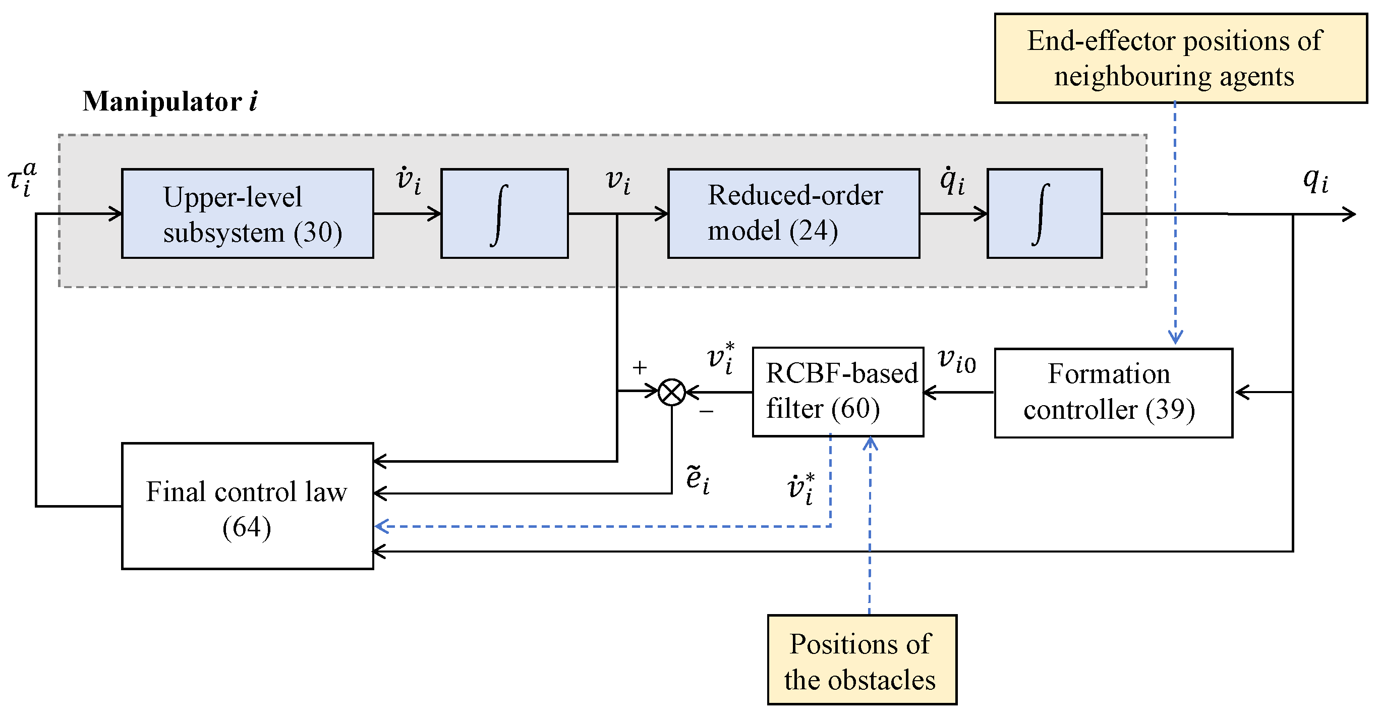
where K e > 0 is the control gain. It is straightforward to verify that the tracking error in Equation (48) asymptotically converges to zero, i.e., v i v i . The detailed proof is standard and hence omitted. See Figure 3 for the overall control framework diagram.
Remark 5. 
In the controller (64), we employ the time derivative v ˙ i . A differentiable closed-form solution to the QP problem in Equation (61) exists when the QP has a single constraint [15], and arbitrarily complex obstacle environments can be represented by a single composite CBF [31]. Therefore, an explicit expression for v ˙ i always exists. In practical implementations, the time derivative v ˙ i can be approximated numerically using finite-difference schemes, as employed in the simulations of this study.

5. Simulations

In this section, the proposed safety-critical end-effector formation control strategy is validated by means of two representative cases.

5.1. Manipulator Group Formed by PA3 Manipulators

Consider a network of N = 4 underactuated manipulators operating in a gravity-free plane. Each manipulator is a four-link mechanism with a passive first joint and three actively driven joints; in accordance with the naming convention adopted in this paper, we refer to it as the PA3 manipulator. The mechanical parameters for the i-th manipulator are
m i , 1 = m i , 2 = 0.3 kg , m i , 3 = m i , 4 = 0.4 kg , L i , 1 = L i , 2 = 0.3 m , L i , 3 = L i , 4 = 0.4 m , l i , 1 = l i , 2 = 0.15 m , l i , 3 = l i , 4 = 0.2 m , I i , 1 = I i , 2 = 0.0022 kg m 2 , I i , 3 = I i , 4 = 0.0053 kg m 2 .
Their base positions in the global X Y plane are p 10 = [ 0 , 0 ] T , p 20 = [ 2.5 , 0 ] T , p 30 = [ 2.5 , 2 ] T , and p 40 = [ 0 , 2 ] T and the orientation offset between each local coordinate frame and the global frame is ϕ i = 0 . All manipulators start from rest ( q ˙ i ( 0 ) = 0 ) with the following joint configurations:
q 1 ( 0 ) = π 3 , π 6 , π 4 , π 8 T , q 2 ( 0 ) = π 4 , 0 , π 3 , π 2 T , q 3 ( 0 ) = 3 π 4 , π 4 , π 3 , π 6 T , q 4 ( 0 ) = 3 π 4 , π 4 , π 2 , π 8 T .
The desired formation is a square of side length 0.7 m, whose interconnection topology is captured by the incidence matrix of the formation graph G .
B = 1 0 0 1 1 1 1 0 0 0 0 1 1 0 1 0 0 1 1 0 .
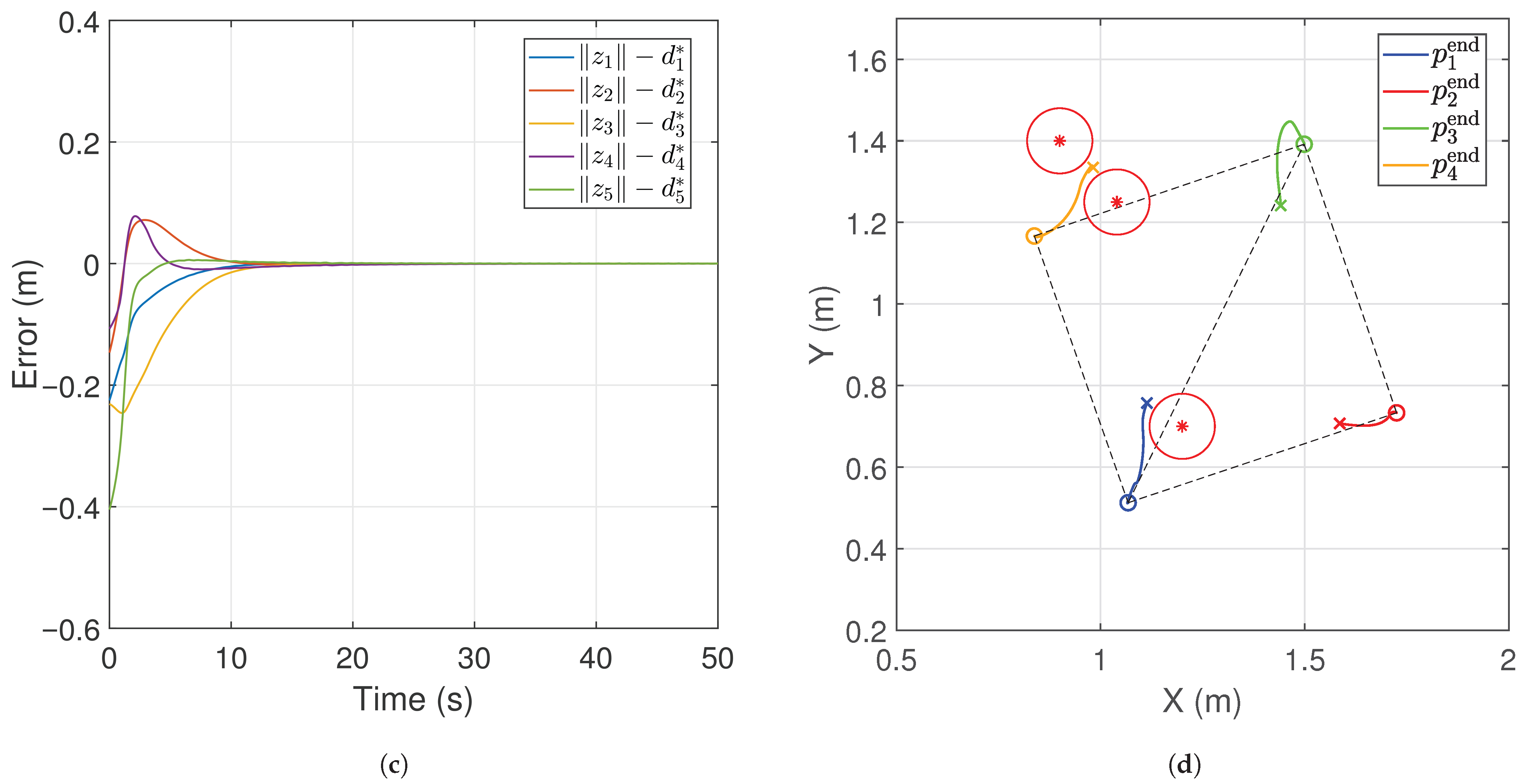
Three circular obstacles—each of radius 0.08 m —are located at ob 1 = [ 1.20 , 0.70 ] , ob 2 = [ 0.90 , 1.40 ] and ob 3 = [ 1.04 , 1.25 ] in the X Y plane.
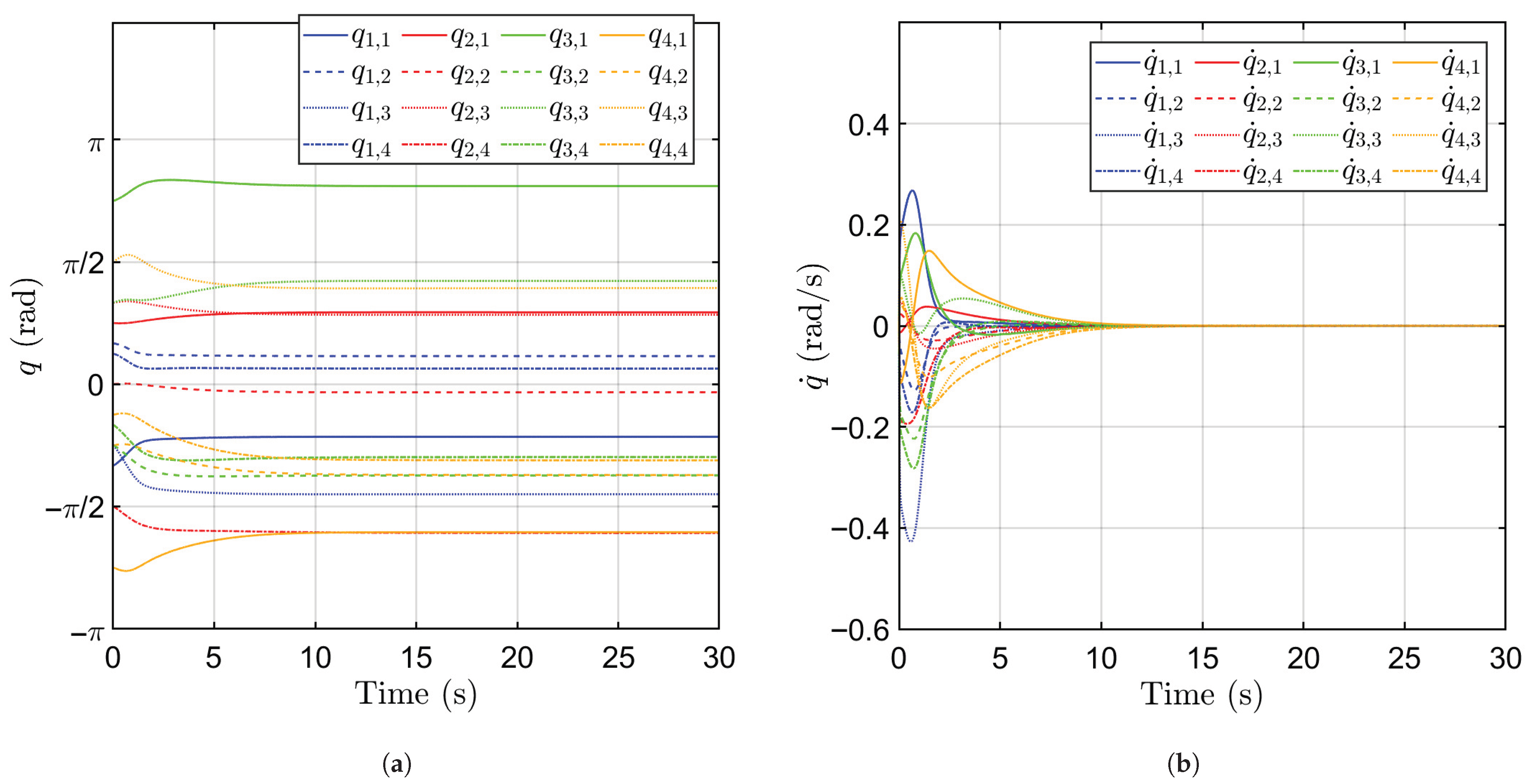
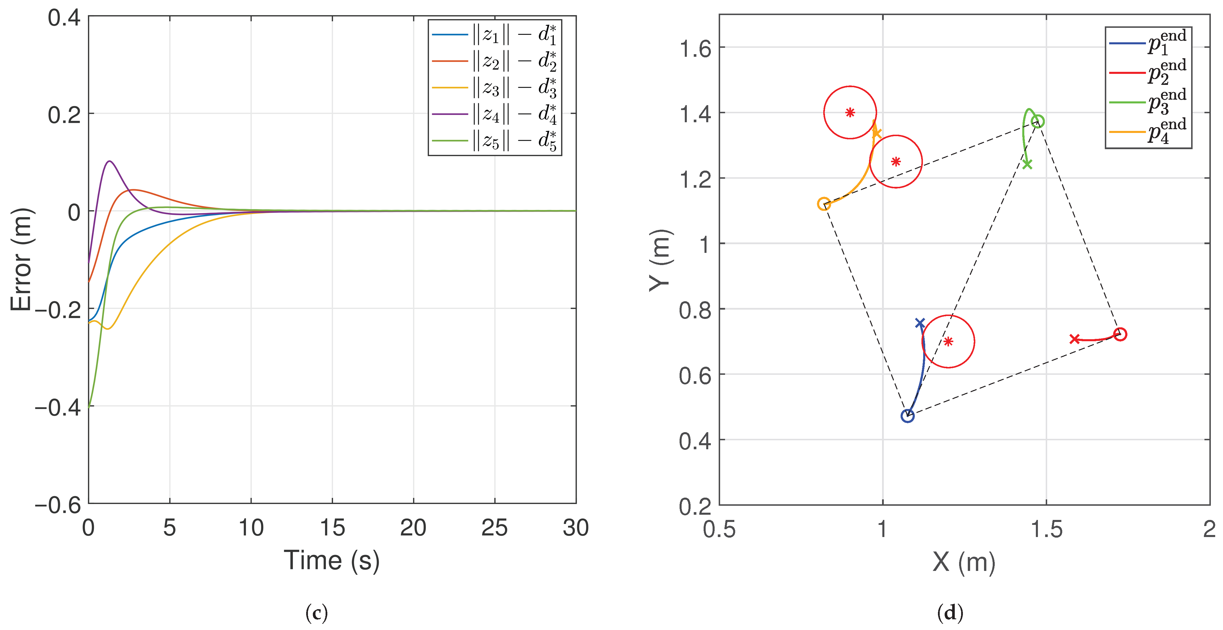
Two sets of comparative simulations were conducted on this group of underactuated manipulators: one without safety constraints (results shown in Figure 4) and the other under the proposed safety-critical controller (results shown in Figure 5). Without considering safety constraints, we use the control law in Equation (64) with v i = v i 0 and control parameters set as K P = 2 and K e = 100 . The simulation results are shown in Figure 4. Sub-figures (a) and (b) depict the convergence of joint angles and velocities to equilibrium. Sub-figure (c) illustrates that the distances defined on each edge of the graph G converge to their desired values, confirming the formation of the target square. Sub-figure (d) shows the trajectories of the networked end-effectors and indicates that manipulators 1 and 4 collide with obstacles, creating a potential safety hazard. These results demonstrate that, the nominal formation control strategy can achieve convergence but may lead to collisions in cluttered environments.
To enforce safety, we use the safety-critical control law in Equation (64) with v i obtained from QP in Equation (61). The control gains remain K P = 2 and K e = 100 , and the RCBF parameters are chosen as κ = 0.5 and ε = 5 . Note that selecting a smaller ε and a larger κ reduces Γ i j ( δ ) and makes the inflated safe set closer to the original one. However, such a choice narrows the feasible range of the controller v i and requires larger control torques (see Equation (56)). In addition, the upper bound of the backstepping tracking error e ˜ i ( t ) can be reduced by choosing a relatively large K e , which in turn decreases Γ i j ( δ ) . However, we also note that excessively large control gains may lead to high control torques. In summary, the values of κ , ε , and K e should be selected by balancing system safety and controller feasibility. As shown in Figure 5, by incorporating the RCBF-based safety filter, the manipulators are able to maintain both formation accuracy and obstacle avoidance simultaneously. This verifies the effectiveness of the safety-critical controller and confirms the theoretical guarantees discussed in Section 4.

5.2. Manipulator Group Including the PA Manipulator

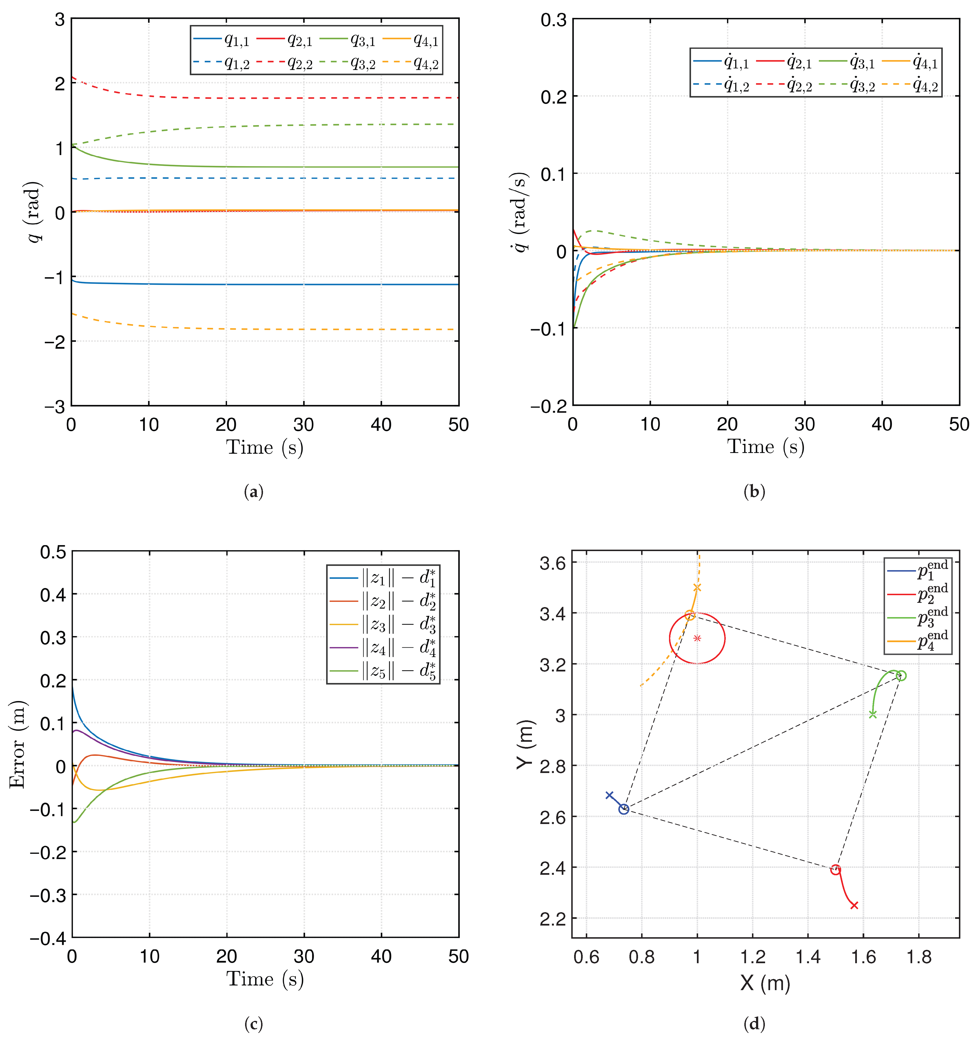
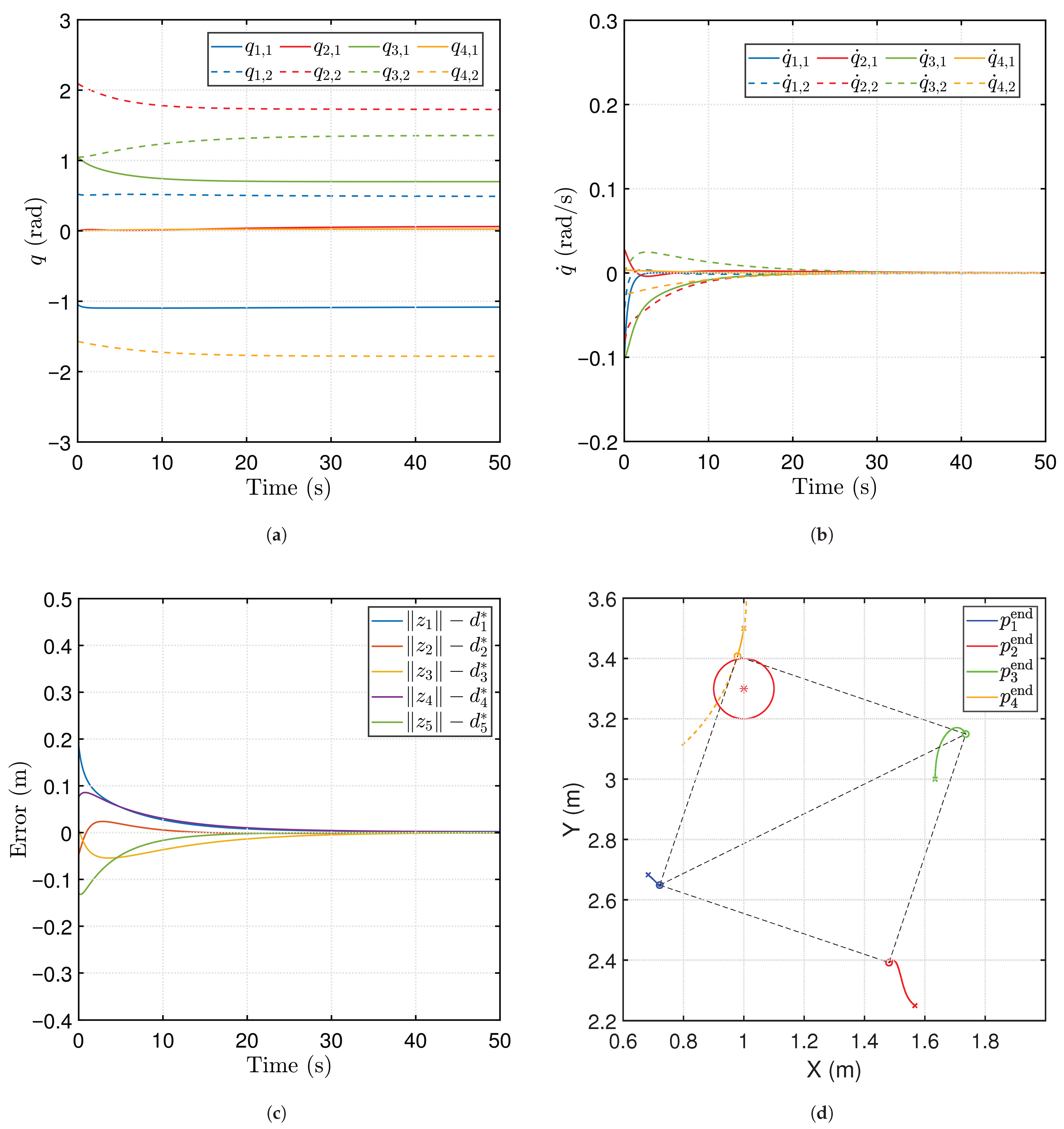
We also consider a network of N = 4 two-link manipulators, one of which is an underactuated PA manipulator. As noted in Remark 1, the PA manipulator’s joint-angle constraint restricts its motion to a predefined curve, thereby reducing its workspace. Accordingly, in this simulation only manipulator 4 is underactuated, while the others remain fully actuated. Even if an obstacle occupies PA manipulator’s limited workspace, the cooperative system can achieve the formation control. All manipulators share the following mechanical parameters: m i , 1 = m i , 2 = 0.2 kg , L i , 1 = L i , 2 = 0.5 m , l i , 1 = l i , 2 = 0.15 m , and I i , 1 = I i , 2 = 0.005 kg m 2 . Their base positions are p 10 = [ 0 , 2 ] T , p 20 = [ 2 , 2 ] T , p 30 = [ 2.5 , 3 ] T , and p 40 = [ 0.5 , 3 ] T , with orientation offsets ϕ i = 0 . The initial joint configurations (with initial joint velocities being zero) are q 1 ( 0 ) = [ π / 3 , π / 6 ] T , q 2 ( 0 ) = [ 0 , 2 π / 3 ] T , q 3 ( 0 ) = [ π / 3 , π / 3 ] T , and q 4 ( 0 ) = [ 0 , π / 2 ] T . The desired formation is a square of side length 0.8 m , with incidence matrix B defined in Equation (67). A circular obstacle of radius 0.1 m is placed at ob 1 = [ 1 , 3.3 ] .
Two sets of comparative simulations were conducted on this group of manipulators: one without safety constraints, implemented using the method in [11] (results shown in Figure 6), and the other under the proposed safety-critical controller (results shown in Figure 7). Without considering safety constraints, we apply the control law in Equation (64) with v i = v i 0 and gains K P = 1 , K e = 100 . In this case, the control law in Equation (64) is indeed in the same form as that proposed in [11]. The simulation results in Figure 6 illustrate that an obstacle lies along the PA manipulator’s path toward its desired equilibrium. Due to without incorporating the safety-guaranteed strategy, the manipulator’s end-effector will collide with that obstacle. To enforce safety, we apply the safety-critical control law in Equation (64) using v i obtained from QP in Equation (61), while keeping K P = 1 and K e = 100 . For the RCBF-based controller we set κ = 0.2 and ε = 20 . Since the PA manipulator cannot deviate from its predefined curve, it stops just before collision (as shown in Figure 7d); Accordingly, the other manipulators adjust their respective desired equilibrium, enabling the cooperative system to achieve the desired formation. Figure 8 presents the distance between the PA manipulator’s end-effector and the obstacle center. Unlike the results in [11], the proposed safety-critical controller ensures that the manipulator remains within the safety boundary.

6. Conclusions and Discussion

6.1. Brief Review of Our Work and Potential Applications

Cooperative control of manipulators has emerged as a growing research focus, motivated by applications such as coordinated object transport, cooperative assembly, and precision tasks requiring multiple arms to act in concert [5,32,33,34,35]. We focus on safety-critical, distributed end-effector formation control for multiple planar underactuated PAn−1 manipulators. This setting arises from actuator faults that induce underactuation, a condition under which conventional controllers fail. It is also motivated by safety-sensitive domains (e.g., hazardous material handling, robotic surgery) that demand guaranteed collision avoidance.
We leverage the integrability of the second-order nonholonomic constraints inherent in PAn−1 manipulators, which enables us to derive a cascaded form of their dynamics. Using this cascaded-form transformation, we extract a reduced-order model for each manipulator and then design a distributed formation controller via a backstepping approach. Tracking errors introduced by the backstepping method may compromise safety by driving the system outside the safety set defined by a general CBF. To mitigate this impact, we incorporate an RCBF into the control law.

6.2. Comparison with Previous Work

Although actuator faults [6,36] and collision-avoidance [9,10] have been studied in multi-agent systems, these works focus on simple agents—whose control inputs directly determine the formation’s state—and do not address severe faults that render the system underactuated. For fully actuated manipulators, a commonly used safety-critical control strategy is to transform the dynamics into a cascaded form and then construct CBFs via the reduced-order model [15,16]. However, As mentioned in the Introduction, the second-order nonholonomic constraints inherent in the underactuated systems make their dynamics generally unable to be transformed into a cascaded form composed of multiple first-order subsystems, which prevents the direct extension of the existing CBF-based methods. Neither our previous studies [11,12] nor other works on single underactuated manipulators [23,25] have addressed safety considerations. To address this challenge, we exploit a key property discussed in [17,18]: for the underactuated PAn−1 manipulator, its second-order coupling can be integrated into a first-order coupling. Exploiting this property, this paper decomposes the dynamics of PAn−1 underactuated manipulators into a cascaded form and thereby constructs a valid CBF. It is important to emphasize that this reduction (from second-order coupling to first-order coupling) does not apply to any other underactuated manipulators. In other words, the method proposed is a specific solution tailored for PAn−1 underactuated manipulators.
The formation control for multi-agent systems generally presents greater complexity than the positioning problem for a single agent. However, it is important to clarify that our proposed CBF-based safety-critical control may not directly extend to the single PAn−1 manipulator’s end-effector positioning problem addressed in [37,38]. The primary difficulty in the end-effector positioning control for a single PAn−1 manipulator arises from the necessity of determining feasible trajectories for actuated joints to achieve a specific position. Introducing obstacle avoidance further complicates this trajectory planning, rendering existing solutions inadequate and complicating the integration of safety-critical methods. Conversely, our study focuses on arranging multiple manipulators into a predefined formation rather than specifying precise individual end-effector positions, thereby bypassing the trajectory-planning challenge and enabling the use of the CBF framework.
In addition, we note two mainstream CBF-based approaches to safety-critical control of cascaded systems. The first is the RCBF method adopted in this work, where the safety controller is designed for the reduced-order model and the tracking error introduced by backstepping is treated as a bounded disturbance. The RCBF-based method guarantees that the closed-loop system remains within an inflated safety set. The second is the CBF backstepping (or safe backstepping) approach [15,16], which provides a theoretical framework for guaranteeing safety in cascaded systems with an arbitrary number of layers. Although this method ensures invariance of the original safety set in principle, it requires the reduced-order subsystem controller to be smooth, thereby tolerating only analytic QP solutions and substantially increasing both derivational and implementation complexity. It often leads to overly conservative safety sets. For the two-layer cascaded system studied here, the RCBF approach offers a more practical balance between safety assurance and implementation simplicity.

6.3. Limitations and Future Research Directions

The present study is confined to collision avoidance at the end-effectors and guarantees asymptotic convergence to a static formation. Future research should therefore consider more complex scenarios, including link-obstacle interactions, dynamic obstacles, and inter-manipulator constraints [39]. Extending the framework to support time-varying formations and incorporating fixed-time control for rapid, predefined-time convergence [40] would also be valuable directions.
Moreover, the success of our approach hinges on the integrability of the second-order nonholonomic constraint—an intrinsic feature of PAn−1 manipulators. Addressing obstacle avoidance for other classes of underactuated manipulators remains an interesting research direction. As noted, due to the lack of such integrability, transforming these systems into cascaded form is generally infeasible. Promising avenues include (i) exploiting structural properties of the dynamics to design exponential CBFs [41]; (ii) computing CBFs online [42] or synthesizing them offline via optimization-based methods [43]; and (iii) going beyond CBFs by employing barrier Lyapunov functions (BLFs) to enforce state constraints, as demonstrated for underactuated cranes in [44].

Author Contributions

Conceptualization, Z.P. and X.X.; Formal analysis, Z.P.; Investigation, Z.P. and X.X.; Methodology, Z.P.; Supervision, X.X.; Validation, Z.P.; Visualization, Z.P.; Writing—original draft, Z.P.; Writing—review and editing, Z.P. and X.X. All authors have read and agreed to the published version of the manuscript.

Funding

This research received no external funding.

Data Availability Statement

All data and original contributions reported in this study are included in this article. Further inquiries can be directed to the corresponding author.

Conflicts of Interest

The authors declare no conflicts of interest.

Abbreviations

The following abbreviations are used in this manuscript:
CBFControl barrier function
CoMCenter of mass
ISSfInput-to-state safe
PAThe two-link manipulator with a passive first joint and an active second joint.
PAn−1The n-link manipulator with a passive first joint and all subsequent joints being active.
QPQuadratic program
RCBFRobust control barrier function

References

  1. Chen, J.; Jayawardhana, B.; De Marina, H.G. Scaling up the formation of agents with heterogeneous sensing: Mixed distance and bearing-only. IEEE Trans. Autom. Control 2024, 69, 8011–8017. [Google Scholar] [CrossRef]
  2. Wang, H.; Li, W.; Ning, J. Collision avoidance and formation tracking control for heterogeneous UAV/USV systems with input quantization. Actuators 2025, 14, 309. [Google Scholar] [CrossRef]
  3. Oh, K.K.; Park, M.C.; Ahn, H.S. A survey of multi-agent formation control. Automatica 2015, 53, 424–440. [Google Scholar] [CrossRef]
  4. Yang, W.; Shi, Z.; Zhong, Y. Distributed robust adaptive formation control of multi-agent systems with heterogeneous uncertainties and directed graphs. Automatica 2023, 157, 111275. [Google Scholar] [CrossRef]
  5. Wu, H.; Jayawardhana, B.; De Marina, H.G.; Xu, D. Distributed formation control for manipulator end-effectors. IEEE Trans. Autom. Control 2023, 68, 5413–5428. [Google Scholar] [CrossRef]
  6. Wang, J.; Li, Y.; Wu, Y.; Liu, Z.; Chen, K.; Chen, C.P. Fixed-time formation control for uncertain nonlinear multiagent systems with time-varying actuator failures. IEEE Trans. Fuzzy Syst. 2024, 32, 1965–1977. [Google Scholar] [CrossRef]
  7. Deng, C.; Jin, X.Z.; Che, W.W.; Wang, H. Learning-based distributed resilient fault-tolerant control method for heterogeneous MASs under unknown leader dynamic. IEEE Trans. Neural Netw. Learn. Syst. 2021, 33, 5504–5513. [Google Scholar] [CrossRef]
  8. Jin, X.; Lü, S.; Yu, J. Adaptive NN-based consensus for a class of nonlinear multiagent systems with actuator faults and faulty networks. IEEE Trans. Neural Netw. Learn. Syst. 2021, 33, 3474–3486. [Google Scholar] [CrossRef] [PubMed]
  9. Yang, G.; An, L.; Zhao, C. Collision/obstacle avoidance coordination of multi-robot systems: A survey. Actuators 2025, 14, 85. [Google Scholar] [CrossRef]
  10. Bai, Y.; Wang, Y.; Svinin, M.; Magid, E.; Sun, R. Adaptive multi-agent coverage control with obstacle avoidance. IEEE Control Syst. Lett. 2021, 6, 944–949. [Google Scholar] [CrossRef]
  11. Peng, Z.; Jayawardhana, B.; Xin, X. Distributed formation control of end-effector of mixed planar fully-and under-actuated manipulators. IEEE Control Syst. Lett. 2023, 7, 3735–3740. [Google Scholar] [CrossRef]
  12. Peng, Z.; Jayawardhana, B.; Xin, X. Distributed end-effector formation control for networked 2-DoF flexible-joint manipulators with partially underactuated agents. Automatica 2025, 179, 112453. [Google Scholar] [CrossRef]
  13. Agrawal, D.R.; Panagou, D. Safe and robust observer-controller synthesis using control barrier functions. IEEE Control Syst. Lett. 2022, 7, 127–132. [Google Scholar] [CrossRef]
  14. Ferraguti, F.; Landi, C.T.; Singletary, A.; Lin, H.C.; Ames, A.; Secchi, C.; Bonfe, M. Safety and efficiency in robotics: The control barrier functions approach. IEEE Robot. Autom. Mag. 2022, 29, 139–151. [Google Scholar] [CrossRef]
  15. Cohen, M.H.; Molnar, T.G.; Ames, A.D. Safety-critical control for autonomous systems: Control barrier functions via reduced-order models. Annu. Rev. Control 2024, 57, 100947. [Google Scholar] [CrossRef]
  16. Taylor, A.J.; Ong, P.; Molnar, T.G.; Ames, A.D. Safe backstepping with control barrier functions. In Proceedings of the 2022 IEEE 61st Conference on Decision and Control (CDC), Cancun, Mexico, 6–9 December 2022; pp. 5775–5782. [Google Scholar]
  17. Oriolo, G.; Nakamura, Y. Control of mechanical systems with second-order nonholonomic constraints: Underactuated manipulators. In Proceedings of the 30th IEEE Conference on Decision and Control, Brighton, UK, 11–13 December 1991; Volume 3, pp. 2398–2403. [Google Scholar]
  18. Lai, X.; She, J.; Cao, W.; Yang, S.X. Stabilization of underactuated planar Acrobot based on motion-state constraints. Int. J. Non-Linear Mech. 2015, 77, 342–347. [Google Scholar] [CrossRef]
  19. Jiang, Z.P.; Nijmeijer, H. Tracking control of mobile robots: A case study in backstepping. Automatica 1997, 33, 1393–1399. [Google Scholar] [CrossRef]
  20. Davila, J. Exact tracking using backstepping control design and high-order sliding modes. IEEE Trans. Autom. Control 2013, 58, 2077–2081. [Google Scholar] [CrossRef]
  21. Li, Y.; Tong, S. Adaptive backstepping control for uncertain nonlinear strict-feedback systems with full state triggering. Automatica 2024, 163, 111574. [Google Scholar] [CrossRef]
  22. Liu, Y.; Xin, X. Controllability and observability of an n-Link planar robot with a single actuator having different actuator–sensor configurations. IEEE Trans. Autom. Control 2015, 61, 1129–1134. [Google Scholar] [CrossRef]
  23. Xin, X.; Liu, Y. Control Design and Analysis for Underactuated Robotic Systems; Springer: Berlin/Heidelberg, Germany, 2014. [Google Scholar]
  24. Spong, M.W.; Hutchinson, S.; Vidyasagar, M. Robot Modeling and Control; John Wiley & Sons: Hoboken, NJ, USA, 2020. [Google Scholar]
  25. Wu, J.; Zhang, P.; Meng, Q.; Wang, Y. Control of Underactuated Manipulators: Design and Optimization; Springer: Berlin/Heidelberg, Germany, 2023. [Google Scholar]
  26. Anderson, B.D.; Yu, C.; Fidan, B.; Hendrickx, J.M. Rigid graph control architectures for autonomous formations. IEEE Control Syst. Mag. 2008, 28, 48–63. [Google Scholar]
  27. Marina, H.G.D. Distributed Formation Control for Autonomous Robots. Ph.D. Thesis, University of Groningen, Groningen, The Netherlands, 2016. [Google Scholar]
  28. Dixon, W.E. Adaptive regulation of amplitude limited robot manipulators with uncertain kinematics and dynamics. IEEE Trans. Autom. Control 2007, 52, 488–493. [Google Scholar] [CrossRef]
  29. Wang, H.; Ren, W.; Cheah, C.C.; Xie, Y.; Lyu, S. Dynamic modularity approach to adaptive control of robotic systems with closed architecture. IEEE Trans. Autom. Control 2020, 65, 2760–2767. [Google Scholar] [CrossRef]
  30. Khalil, H.K. Nonlinear Systems, 3rd ed.; Prentice-Hall: Upper Saddle River, NJ, USA, 2002. [Google Scholar]
  31. Molnar, T.G.; Ames, A.D. Composing control barrier functions for complex safety specifications. IEEE Control Syst. Lett. 2023, 7, 3615–3620. [Google Scholar] [CrossRef]
  32. Chen, T.; Shan, J. Distributed tracking of a class of underactuated Lagrangian systems with uncertain parameters and actuator faults. IEEE Trans. Ind. Electron. 2019, 67, 4244–4253. [Google Scholar] [CrossRef]
  33. Liu, Y.; Li, L. Adaptive leader-follower consensus control of multiple flexible manipulators with actuator failures and parameter uncertainties. IEEE/CAA J. Autom. Sin. 2023, 10, 1020–1031. [Google Scholar] [CrossRef]
  34. Liu, Y.; Yao, X.; Zhao, W. Distributed neural-based fault-tolerant control of multiple flexible manipulators with input saturations. Automatica 2023, 156, 111202. [Google Scholar] [CrossRef]
  35. Yao, X.Y.; Park, J.H.; Ding, H.F.; Ge, M.F. Event-triggered consensus control for networked underactuated robotic systems. IEEE Trans. Cybern. 2022, 52, 2896–2906. [Google Scholar] [CrossRef] [PubMed]
  36. Wang, J.; Hu, Z.; Liu, J.; Zhang, Y.; Gu, Y.; Huang, W.; Tang, R.; Wang, F. Adaptive self-triggered control for multi-agent systems with actuator failures and time-varying state constraints. Actuators 2023, 12, 364. [Google Scholar] [CrossRef]
  37. Wang, Y.; Lai, X.; Zhang, P.; Su, C.Y.; Wu, M. A new control method for planar four-link underactuated manipulator based on intelligence optimization. Nonlinear Dyn. 2019, 96, 573–583. [Google Scholar] [CrossRef]
  38. Wang, Y.; Lai, X.; Zhang, P.; Wu, M. Control strategy based on model reduction and online intelligent calculation for planar n-link underactuated manipulators. IEEE Trans. Syst. Man Cybern. Syst. 2020, 50, 1046–1054. [Google Scholar] [CrossRef]
  39. Şekercioğlu, P.; Jayawardhana, B.; Sarras, I.; Loria, A.; Marzat, J. Formation control of cooperative-competitive robot manipulators with inter-agent constraints. IFAC-PapersOnLine 2024, 58, 49–54. [Google Scholar] [CrossRef]
  40. Ning, B.; Han, Q.L.; Ding, L. A brief overview of recent advances in distributed accelerated secondary control for islanded AC microgrids. IEEE Trans. Ind. Inform. 2025, 21, 6605–6614. [Google Scholar] [CrossRef]
  41. Nguyen, Q.; Sreenath, K. Exponential control barrier functions for enforcing high relative-degree safety-critical constraints. In Proceedings of the 2016 American Control Conference (ACC), Boston, MA, USA, 6–8 July 2016; pp. 322–328. [Google Scholar]
  42. Wabersich, K.P.; Zeilinger, M.N. Predictive control barrier functions: Enhanced safety mechanisms for learning-based control. IEEE Trans. Autom. Control 2022, 68, 2638–2651. [Google Scholar] [CrossRef]
  43. Zhao, P.; Ghabcheloo, R.; Cheng, Y.; Abdi, H.; Hovakimyan, N. Convex synthesis of control barrier functions under input constraints. IEEE Control Syst. Lett. 2023, 7, 3102–3107. [Google Scholar] [CrossRef]
  44. Chen, H.; Sun, N. Nonlinear control of underactuated systems subject to both actuated and unactuated state constraints with experimental verification. IEEE Trans. Ind. Electron. 2019, 67, 7702–7714. [Google Scholar] [CrossRef]
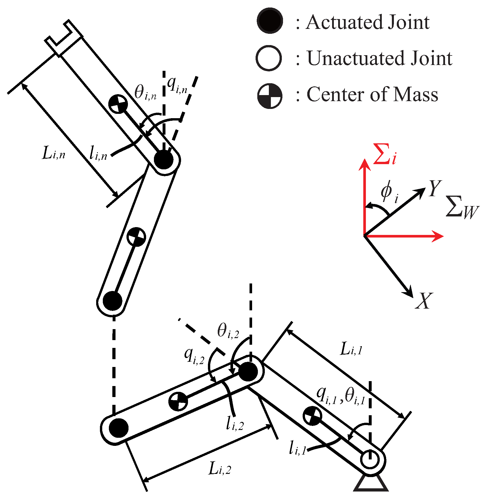
Figure 1. The PAn−1 manipulator: passive (unactuated) base joint and active (actuated) n 1 subsequent joints.
Actuators 14 00475 g001
Figure 2. The primary control objectives: end-effector formation keeping and obstacle avoidance.
Actuators 14 00475 g002
Figure 3. Diagram of the proposed safety-critical end-effector formation controller. Black solid lines denote real physical signals, while blue dashed lines indicate auxiliary information for controller design. Neighboring end-effector and obstacle positions can be obtained via attached cameras.
Actuators 14 00475 g003
Figure 4. The simulation results for a group of four PA3 manipulators without obstacle-avoidance considerations are as follows: (a) Joint angles; (b) Joint velocities; (c) End-effector distance errors; (d) Trajectories of the end-effectors, with × and ∘ denoting the initial and final positions, respectively. Red circles denotes obstacles.
Actuators 14 00475 g004aActuators 14 00475 g004b
Figure 5. The simulation results for a group of four PA3 manipulators with obstacle-avoidance considerations are as follows: (a) Joint angles; (b) Joint velocities; (c) End-effector distance errors; (d) Trajectories of the end-effectors, with × and ∘ denoting the initial and final positions, respectively. Red circles denotes obstacles.
Actuators 14 00475 g005aActuators 14 00475 g005b
Figure 6. The simulation results for a group of four two-link manipulators without obstacle-avoidance considerations (using the method in [11]), where one is the PA manipulator (manipulator 4) and the other three are fully actuated, are as follows: (a) Joint angles; (b) Joint velocities; (c) End-effector distance errors; (d) Trajectories of the end-effectors, with × and ∘ denoting the initial and final positions, respectively. The colored dashed curve represents the PA manipulator’s workspace, with the red circle indicating the obstacle.
Actuators 14 00475 g006
Figure 7. The simulation results for a group of four two-link manipulators with obstacle-avoidance considerations, where one is the PA manipulator (manipulator 4) and the other three are fully actuated, are as follows: (a) Joint angles; (b) Joint velocities; (c) End-effector distance errors; (d) Trajectories of the end-effectors, with × and ∘ denoting the initial and final positions, respectively. The colored dashed curve represents the PA manipulator’s workspace, with the red circle indicating the obstacle.
Actuators 14 00475 g007
Figure 8. Distance from the end-effector of the PA manipulator to the obstacle center: (a) without obstacle-avoidance considerations (using the method in [11]); (b) under the RCBF-based safety-critical controller proposed in this paper. The red dash line indicates the safety boundary.
Actuators 14 00475 g008
Disclaimer/Publisher’s Note: The statements, opinions and data contained in all publications are solely those of the individual author(s) and contributor(s) and not of MDPI and/or the editor(s). MDPI and/or the editor(s) disclaim responsibility for any injury to people or property resulting from any ideas, methods, instructions or products referred to in the content.