1. Introduction
In actual operating conditions, the inlet of the helical-axial multiphase pump often experiences non-uniform inflow due to factors such as pipeline layout, flow pattern evolution, and interphase interactions. Among these, stratified flow and slug flow, which are most common in actual operating conditions, can lead to phase distribution imbalance in the impeller region, aggravate the gas blockage phenomenon, induce hydraulic pulsation, efficiency degradation, and head fluctuation, and even cause cavitation and mechanical vibration in severe cases, thereby affecting the efficient and safe operation of the multiphase transport system [
1,
2,
3,
4]. Studies have shown that flow pattern change and non-uniform phase distribution of the flow medium at the inlet are among the main factors affecting the multiphase pump. The internal flow resistance caused by turbulent dissipation in the multiphase flow pipeline and the off-design condition pressure drop caused by pressure gradient fluctuation result in non-ideal flow, which can severely affect the efficient, safe, and reliable operation of multiphase pumps. In [
5,
6,
7,
8,
9], the authors investigated the effect of non-uniform inflow on the performance of a water-jet propulsion pump, finding that non-uniformity at the suction inlet led to a significant decrease in the pump head. Luo X [
10] studied the mechanism of energy loss and pressure fluctuation caused by non-uniform inflow in a water-jet propulsion pump, demonstrating that non-uniform inflow reduces head and efficiency while increasing impeller axial force fluctuation, resulting in large pulsations in unsteady energy performance.
Traditional improvement methods mainly focus on pump body structure optimization or operation parameter adjustment. Zhang et al. [
11] proposed three modification methods, namely, adding a splitter blade to the blade trailing edge, blade perforation, and adding a T-shaped blade, all of which were verified by numerical calculation. The results showed that all three modification methods can improve the boosting capacity of the multiphase pump. Han Wei’s research group [
12,
13,
14,
15] proposed modification schemes including slotting treatment of the blades, modifying the leading edge of the blades with bionics, installing a turbulence generator on the blades, and adding a flap, achieving considerable progress. However, regulation ability remained limited in the face of complex and variable inlet conditions.
In recent years, static mixers, as flow field homogenization devices without moving parts, have shown significant advantages in the process industry due to their simple structure, low energy consumption, and ease of integration. In the Poseidon multiphase pump test, it was found that by setting a homogenizer at the front end of the pump, the flow at the multiphase pump inlet was more stable after the buffer mixing effect of the buffer while maintaining the rotational speed [
16]. The FRAMO Company designed a buffer homogenizer at the inlet. Experimental studies have found that after the incoming flow passes through the buffer homogenizer, the gas holdup is more stable than before, which greatly alleviates the harsh conditions at the pump inlet [
17]. Zhang Jinya et al. [
18] conducted gas–liquid two-phase visualization experiments at the impeller inlet and installed a buffer homogenization device at the front end of the multiphase pump. This device reduced the uneven gas–liquid conditions at the pump inlet [
19]. Among them, the helical static mixer, with its unique swirl shear mechanism, can efficiently break up gas-phase clusters and promote interphase mixing, providing a new approach for optimizing inlet flow patterns. Static mixers are mainly classified into plate, helical, helical blade, and grid mixers, among others, according to their structure and working principle. Different types of mixers have different advantages in specific applications and are suitable for different fluid mixing requirements. Wang’s team [
20] first systematically conducted experiments on gas–liquid two-phase helical flow in horizontal pipes. They used a high-speed camera to study the flow pattern of gas–liquid two-phase helical flow in horizontal pipes and found that the distribution of two-phase flow was more complex in helical flow, making the gas and liquid phases more evenly distributed in the pipe. Therefore, helical static mixers are the preferred solution for gas–liquid two-phase flow mixing problems thanks to their excellent fluid disturbance capability, low flow resistance, and outstanding bubble breakup effect [
21].
This paper proposes an innovative scheme integrating a helical static mixer in the front stage of a helical axial-flow multiphase pump, aiming to actively intervene in the flow field through a pre-mixing section in order to achieve homogenization reconstruction of non-uniform inflow (stratified flow and slug flow). The optimal structural parameters of the mixer are obtained through a Box–Behnken design. The influence of the helical static mixer on the head, efficiency, and internal flow characteristics of the multiphase pump after optimizing the non-uniform inflow is investigated using computational fluid dynamics (CFD) multiphase flow simulation, which provides a new solution for the efficient and stable operation of multiphase pumps under non-uniform inflow conditions.
2. Optimization Design of Helical Static Mixers
Unlike traditional mechanical mixers that rely on moving parts, this static mixer is based on fixed helical blade disturbance elements, inducing rotational motion and enhancing turbulence intensity as fluid flows through. The core mechanism lies in the strong shear force generated by the helical flow channel; as shown in
Figure 1, this efficiently breaks gas bubbles and liquid droplet clusters, while the fluid rotation enhancement promotes sufficient contact between the gas and liquid phases. Furthermore, the helix angle and number of blades can be optimized to adapt to flow rate variations, thereby improving mixing efficiency while minimizing flow resistance.
When designing a helical static mixer, the primary task is to rationally determine its various design parameters. These parameters largely dictate the mixer’s actual working capacity and mixing efficiency in gas–liquid two-phase flows. For the structure of a helical static mixer, four factors are crucial to its mixing ability: the helix angle of the front, the helix angle of the rear, the unit length, and the blade thickness.
Therefore, this paper employs the Box–Behnken Design (BBD) experimental design method in Design-Expert software to optimize the mixing design of the helical static mixer with respect to these four influencing factors. The results of the experimental design are presented in
Table 1.
The design points and corresponding simulation results derived from the BBD methodology are presented in
Table 2.
The regression equation fitted for efficiency is expressed in Equation (1).
Analysis of variance was performed on the fitted regression equation for efficiency, with the results presented in
Table 3. The model’s
p-value is substantially less than 0.05, indicating that these four independent variables significantly impact pump efficiency. Significance testing of the
p-value and
t-value reveals a large F-statistic coupled with a small
p-value, demonstrating that the derived regression equation is statistically significant. Furthermore, the coefficient of determination reaches 98.52%, approaching unity, confirming its accuracy in predicting changes in the dependent variable relative to variations in the independent variables.
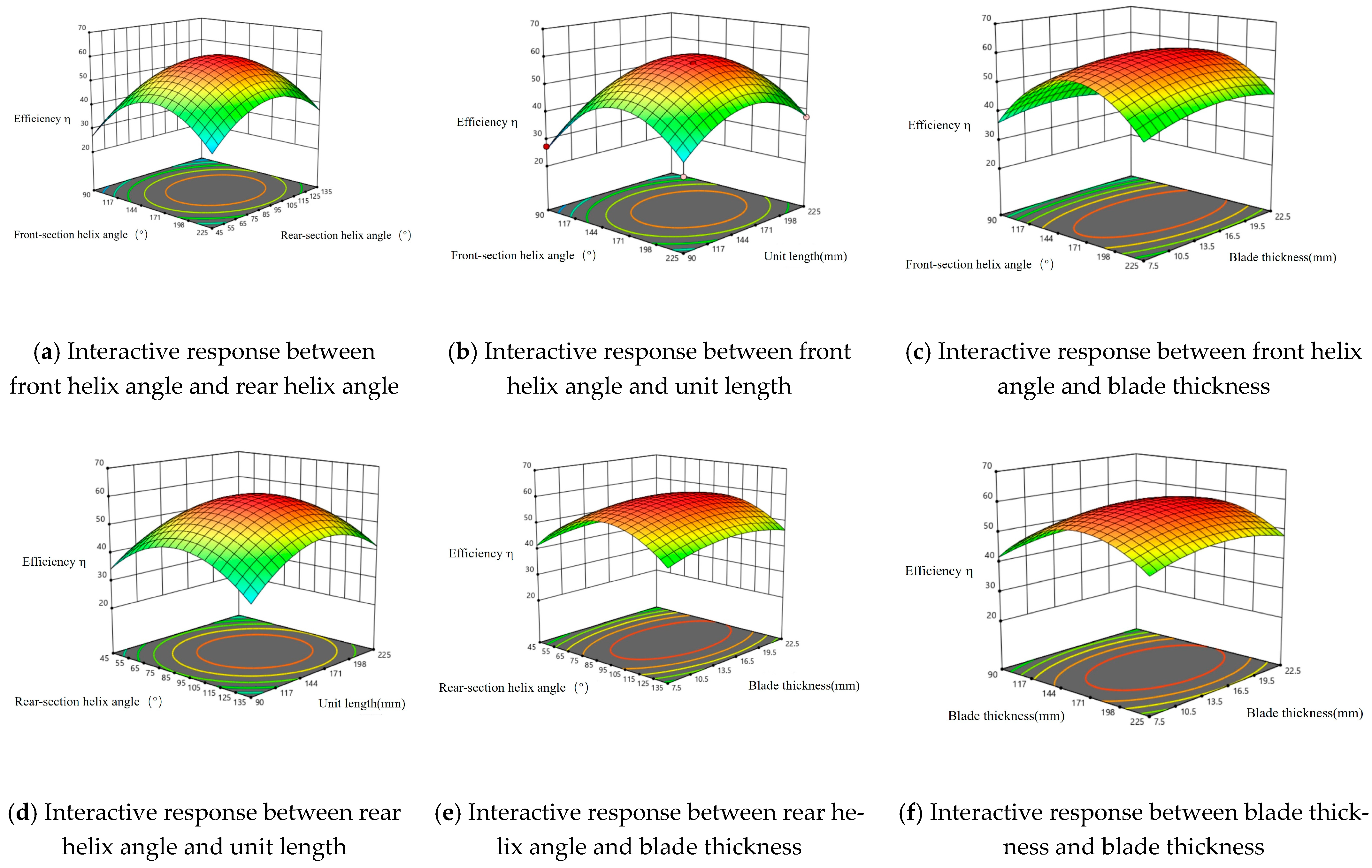
The interaction between the four variables was analyzed using three-dimensional response surface graphs. As shown in
Figure 2, when the unit length is 150 mm and the blade thickness is 15 mm, with the front helix angle fixed, the efficiency first increases and then decreases as the rear helix angle increases; the same trend is observed when the rear helix angle is fixed. When the front helix angle is 150° and the rear helix angle is 90°, with the unit length kept constant, increasing the blade thickness has little effect on efficiency. However, when the blade thickness is fixed, the efficiency first increases and then decreases as the unit length increases.
The fitted regression equation for the pump head is given by Equation (2).
As shown in
Table 4. Its
p-value is also less than 0.0001, which proves that the four independent variables have a significant impact on the head. Meanwhile, the coefficient of determination R
2 = 96.52%, indicating that the model has a good fitting effect on the data. Additionally, the
p-value of the model is much less than 0.05, which indicates that these four independent variables have a significant impact on the pump efficiency. Moreover, through the significance test based on
p-values and T-values, the large F-value and small
p-value further confirm that the obtained regression equation is significant.
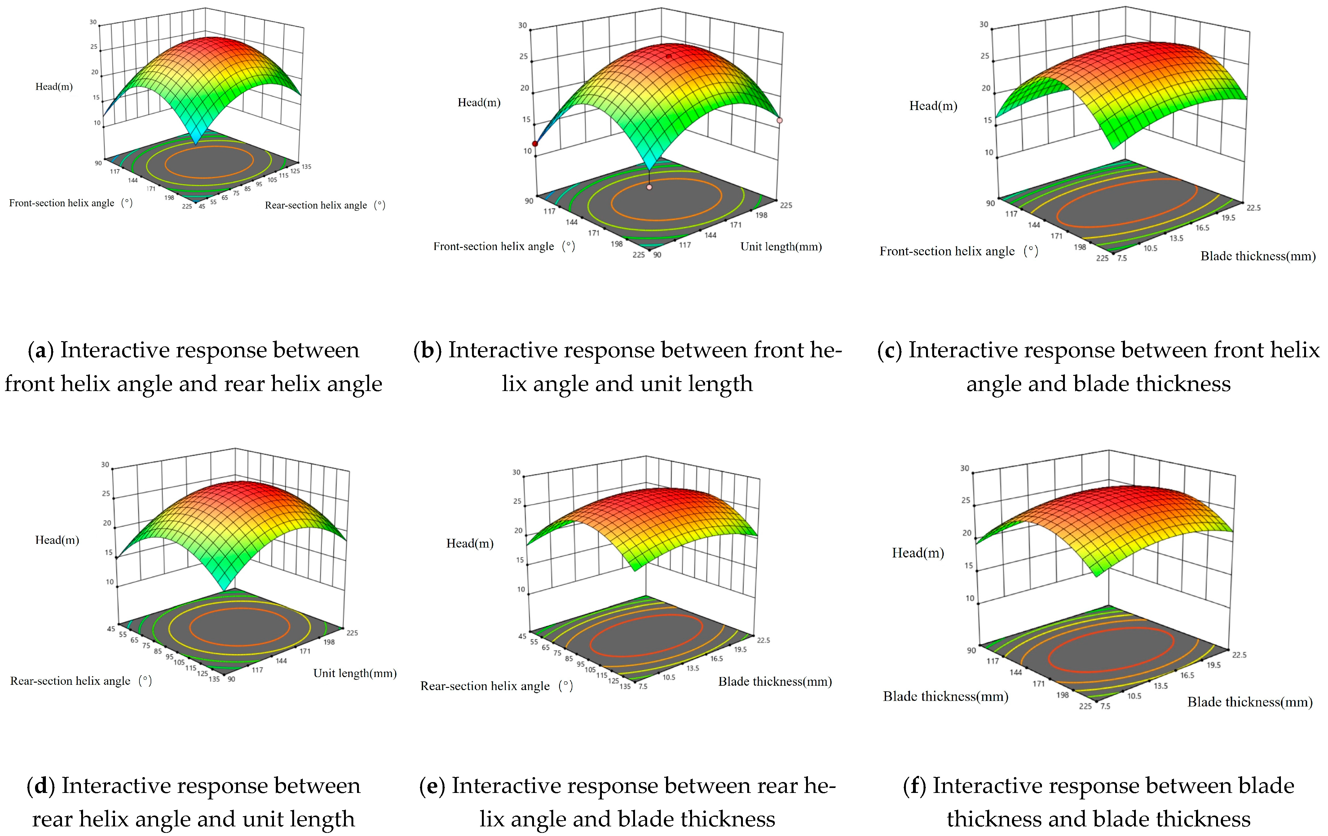
The interaction effects among the four variables were analyzed using three-dimensional response surface graphs, as illustrated in
Figure 3.
Similar to the effect of variable interactions on efficiency, when the unit length is 150 mm and the blade thickness is 15 mm, with the front helix angle fixed, increasing the rear helix angle will cause the head to first increase and then decrease; the same trend applies when the rear helix angle is fixed. However, when the front helix angle is 150° and the rear helix angle is 90°, with the unit length kept constant, increasing the blade thickness has little impact on efficiency. Nevertheless, when the blade thickness is fixed, the efficiency shows< a trend of first increasing and then decreasing as the unit length increases.
To enhance both the head and efficiency of the multiphase pump, a mathematical model is established with the maximum head and maximum efficiency as the objective functions; the value ranges of the four factors are set as constraints, as follows.
Precise optimization was conducted based on the regression equation and the imposed constraint conditions, finally obtaining the parameter combination shown in
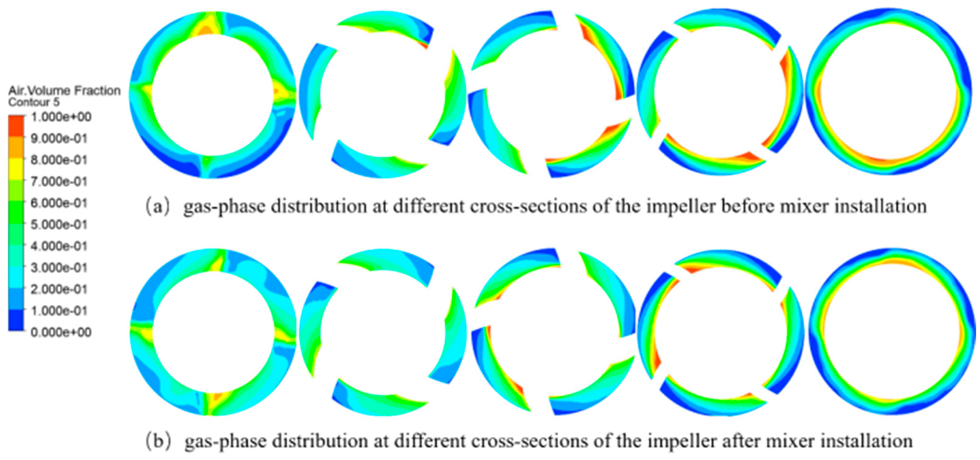
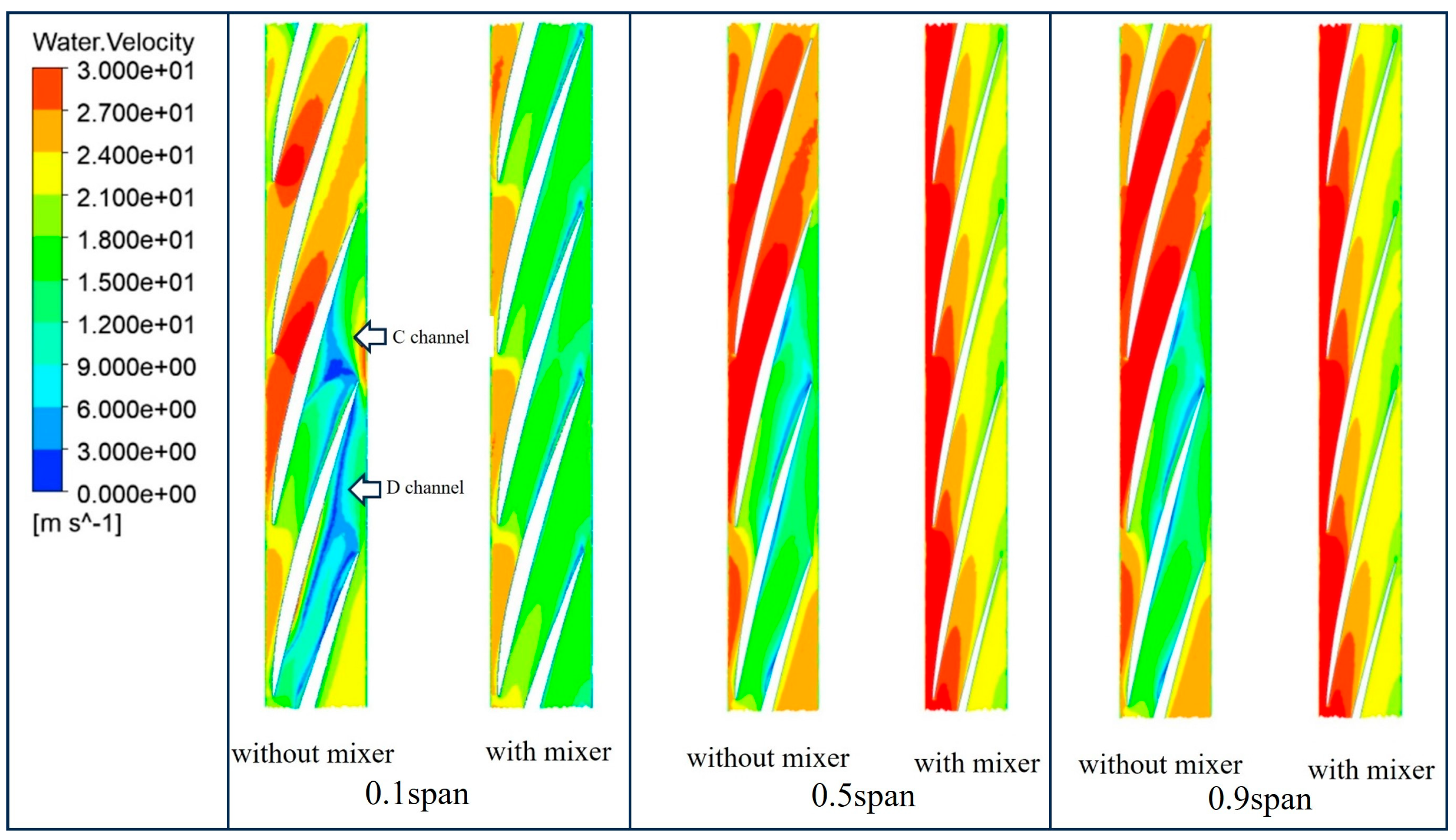
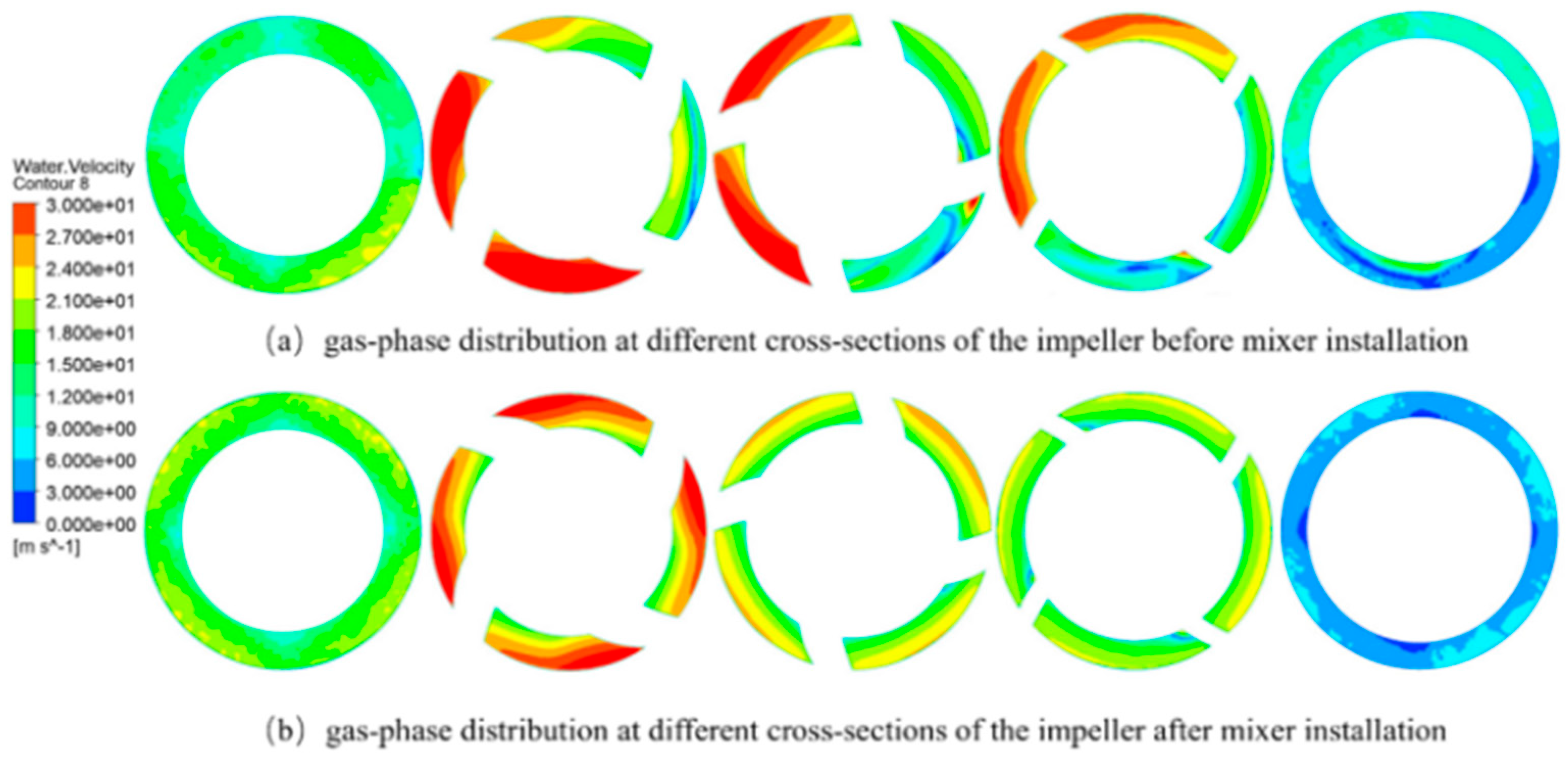
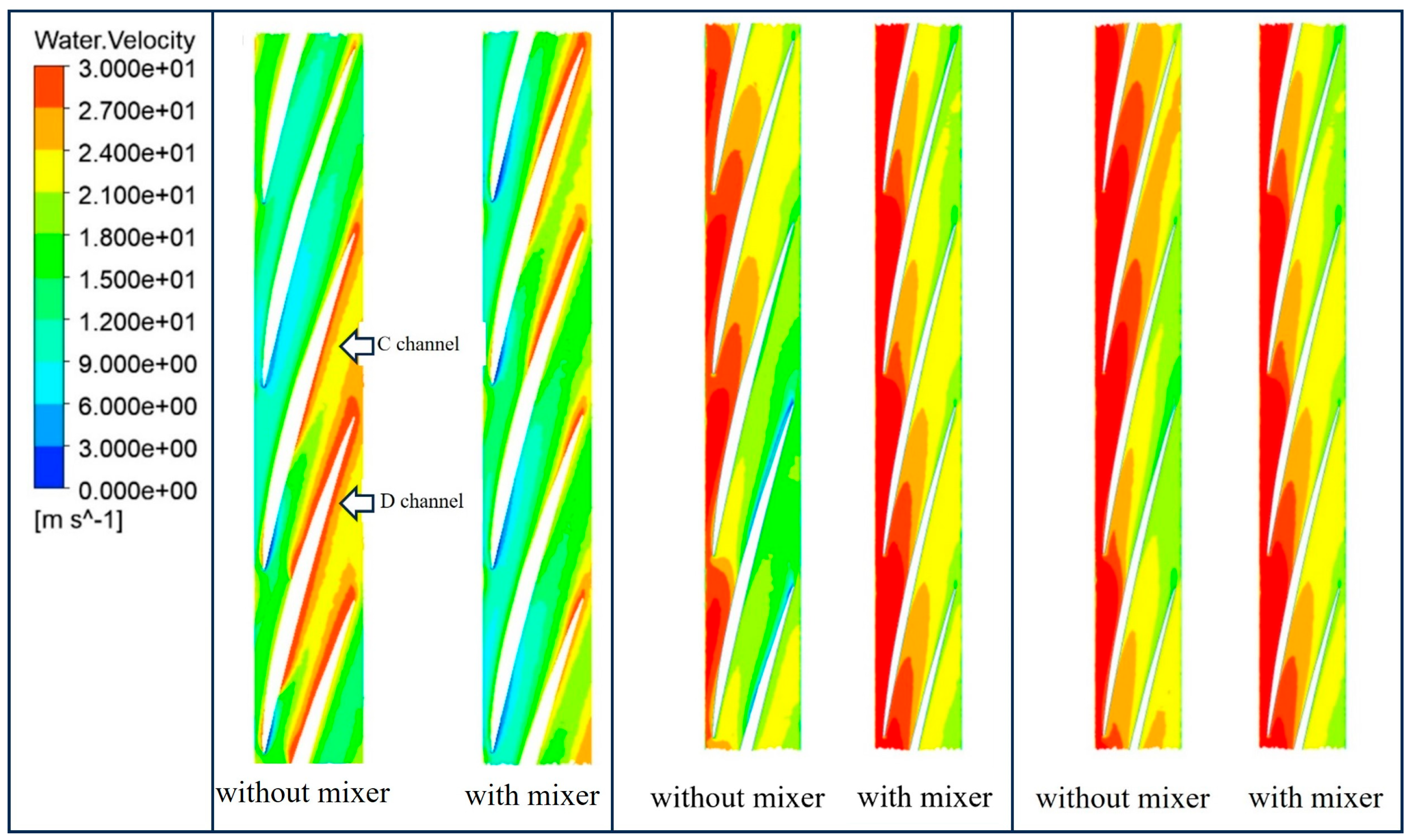
Table 5. To further illustrate the good improvement effect on non-uniform flow of the mixer designed under these parameters, the internal flow fields of the multiphase pump before and after adding the mixer are compared and analyzed below.
In the design of static mixers, the pressure drop generated during design directly reflects the energy loss when fluid passes through the mixer. If the pressure drop is too high, the pump will need to do extra work to maintain the flow rate, resulting in increased energy consumption. Therefore, it is necessary to calculate the pressure drop and compare the calculated pressure drop ΔP with the allowable pressure drop ΔP
allow. If ΔP ≤ ΔP
allow, the design is feasible; if ΔP > ΔP
allow, the design needs to be optimized. First, the allowable pressure drop ΔP
allow is calculated as follows.
The calculation result shows that the allowable pressure drop ΔP
allow is 294.3 kPa. The pressure drop calculation formula for the helical static mixer is given in Equation (5). The calculated result is ΔP = 32.6 kPa, which is much smaller than the value of ΔP
allow. Therefore, the design is reasonable.
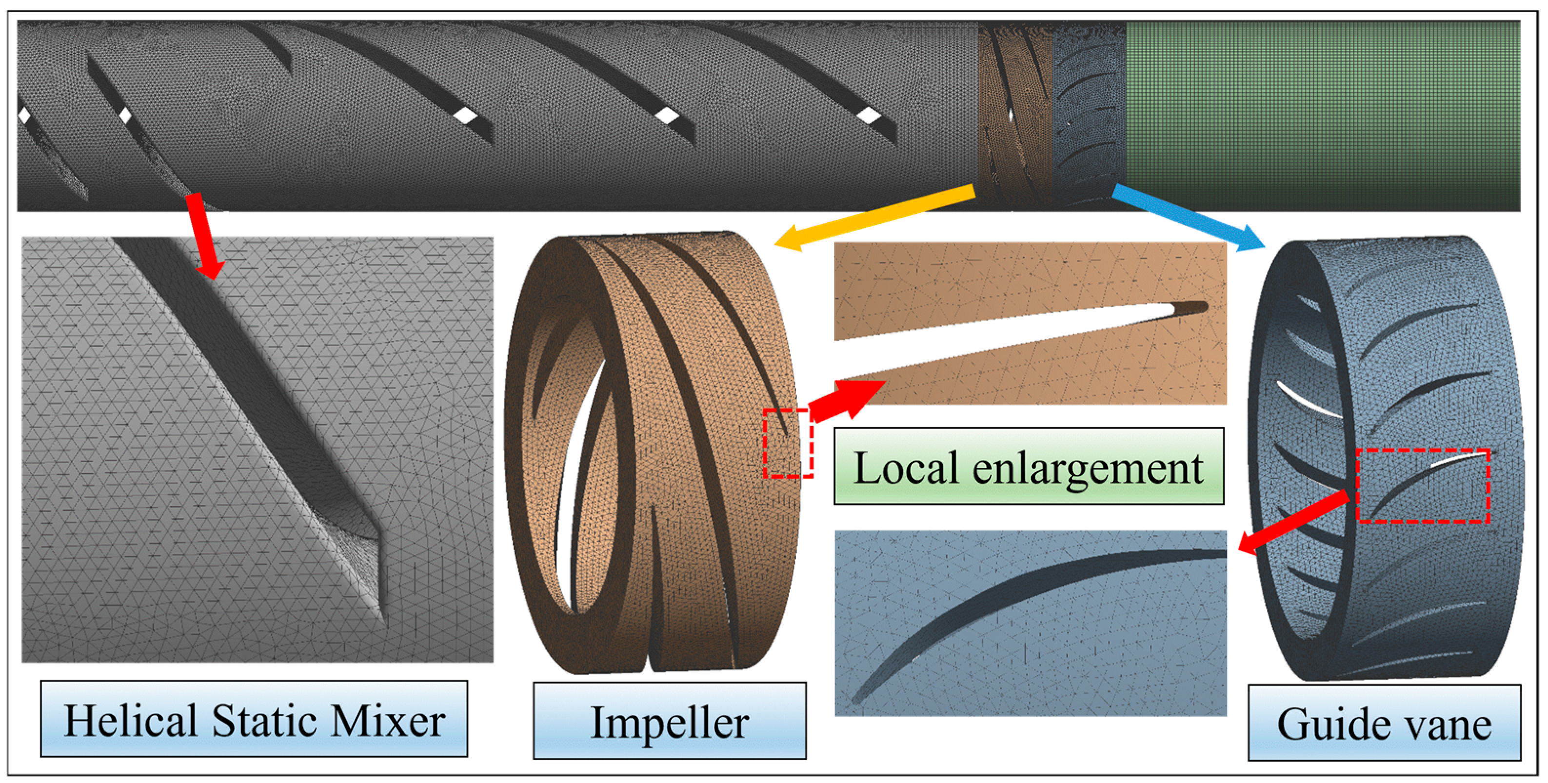
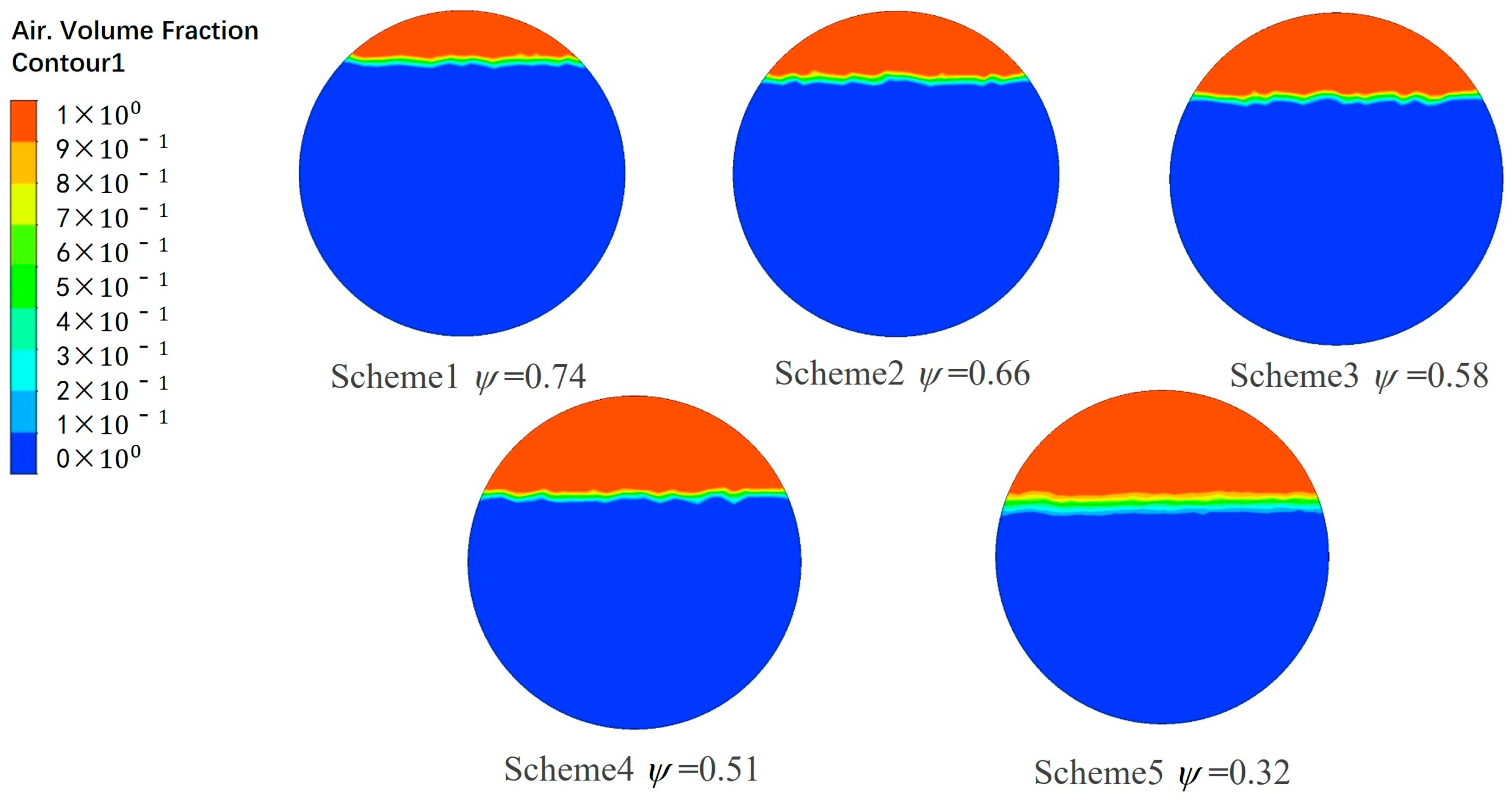
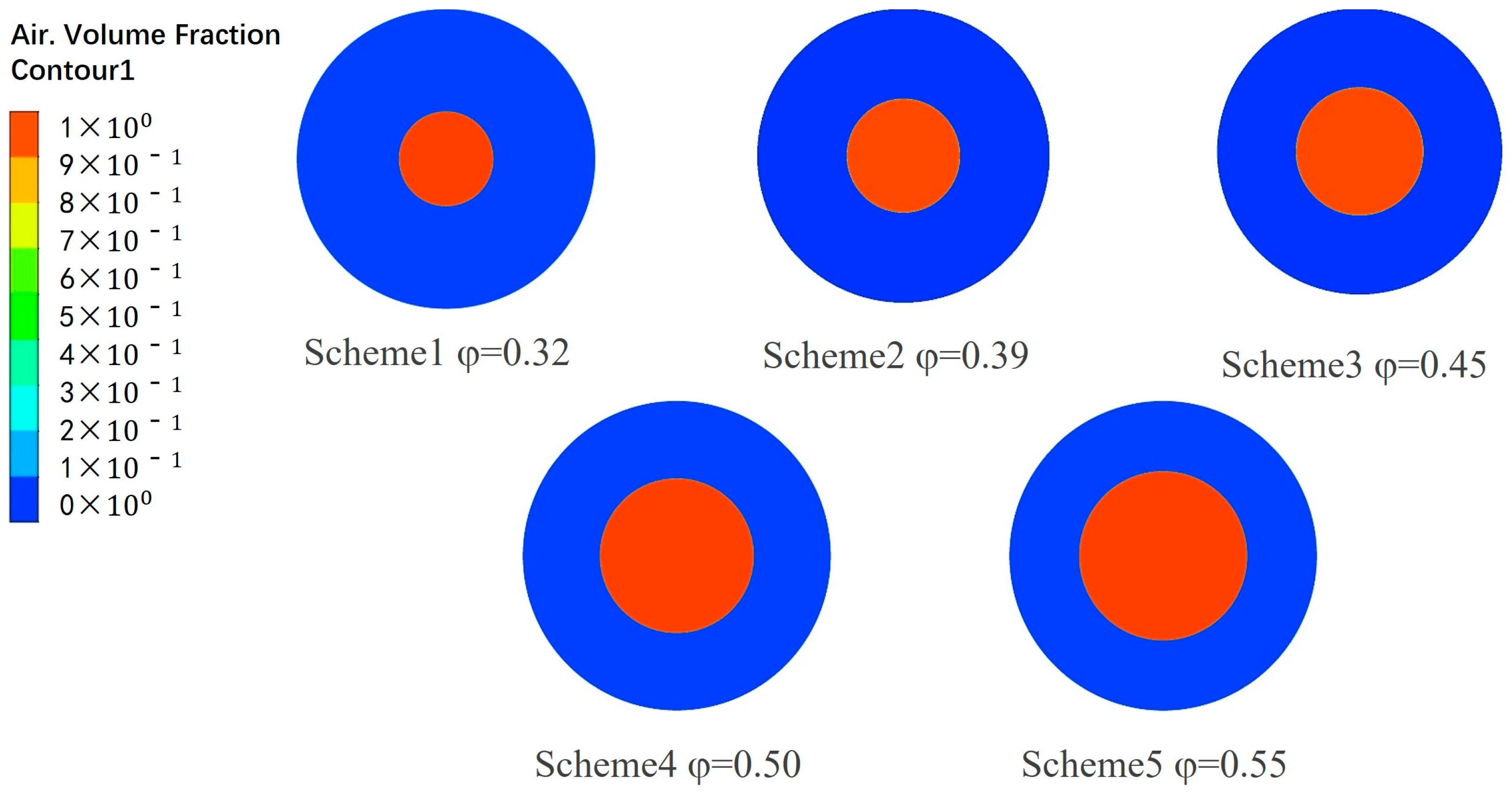
Based on the above parameters, three-dimensional modeling and design of the helical static mixer structure were carried out using SolidWorks2024 software. An inlet extension section was added at the inlet of the mixer to ensure that the two-phase medium enters in a non-uniform form. Finally, it was assembled with the impeller, guide vane, and inlet/outlet water bodies. The numerical calculation model is shown in
Figure 4.
The fluid model was mainly meshed using ANSYS 2022 ICEM CFD software. Due to the complex structure of the mixer, impeller, and guide vane components, which require high mesh adaptability, tetrahedral unstructured meshes were selected [
22,
23,
24,
25,
26,
27]. Unstructured meshes can overcome node structure limitations, and are extremely flexible when dealing with complex boundaries and meshing. They can adapt well to the irregular shapes of the mixer, impeller, and guide vanes, and can accurately simulate internal flow. Finally, the mesh model was evaluated by combining the grid convergence index (GCI), ultimately demonstrating that the mesh model with 14.54 million units is superior in numerical calculation, as shown in
Figure 5.
This study employed the ANSYS 2022 Fluent CFD software platform for numerical simulation. The simulation was set as a transient calculation to accurately capture the dynamic interface changes and unstable flow characteristics in the multiphase flow field. The SST k-ω turbulence model, which is widely used in the simulation of internal flows in fluid machinery, was selected. This model can effectively handle near-wall flow and core separation flow, making it suitable for simulating the complex turbulent phenomena within the mixed transport pump. The high-order scheme was adopted for numerical discretization, and the coupled algorithm was used for pressure–velocity coupling to ensure calculation accuracy and stability.

