Abstract
Among various motor-controlled hydraulic cylinder (MCC) topologies, the two-motor-two-pump (2M2P) MCC distinguishes itself through several notable advantages, including precise cylinder pressure control and eliminating mode switch oscillations. Nevertheless, there are challenges remaining in fully realizing its operations across four quadrants and establishing an effective load-holding function within these operations. This study bridges this gap by implementing a 2M2P MCC prototype on a laboratory knuckle boom crane, enabling operation across all four quadrants. Experimental results indicate that position tracking errors remain within ±2.5 mm across three cases, which is well below 1% of the total cylinder travels in the experiments. Furthermore, smooth intersection of cylinder-bore-side and rod-side pressures is observed during transitions between quadrants. In conclusion, the proposed 2M2P MCC demonstrates seamless operation throughout all quadrants, with the load-holding function smoothly activating and deactivating in all four quadrants.
1. Introduction
Hydraulic cylinders are essential to heavy-duty industries due to their inherent advantages, including high power density, shock loads protection, and reliability in harsh operational environments. Although the valve-controlled hydraulic cylinder has the benefit of being simple, robust, and well-established, it has a relatively low efficiency attributed to the valve throttling [1].
In light of the ongoing climate crisis, the importance of energy efficiency is increased. Therefore, transitioning to a non-valve hydraulic cylinder control system represents a viable strategy for eliminating valve-throttling losses. This is achieved through direct connection of the hydraulic pumps and the cylinder without any control valves in the flow path. The non-valve hydraulic cylinder control system has received significant attention from academia and has seen substantial developments in recent years [2,3,4]. This system has two main trends in focus: the pump-controlled hydraulic cylinder (PCC) and the motor-controlled hydraulic cylinder (MCC) [5]. In a PCC, the control element is the variable-displacement hydraulic pump(s) driven by a constant-speed prime mover, either an electric motor or a combustion engine. Consequently, the cylinder motion is controlled by the pump displacement. PCCs have been intensively developed since the year 2000, primarily focusing on off-road mobile machinery [6,7,8,9]. Nonetheless, a PCC exhibits certain drawbacks when compared to an MCC. Variable-displacement pumps are more costly and less efficient than fixed-displacement pumps when operating under partial load [10,11]. Additionally, the prime mover in idling mode results in energy losses, noise generation, and excess heat [10]. Furthermore, swashplate control systems and external low-pressure sources compromise system compactness and contribute to increased energy losses. As a result, the academic and industrial sectors are gradually shifting their focus away from PCCs, giving more attention to MCCs [3].
In an MCC, electric servo motor(s) driving fixed-displacement hydraulic pump(s) are used. The motion of the hydraulic cylinder is controlled by manipulating the electric servo motor velocities. MCCs can be categorized into various topologies based on the number of electric servo motors and hydraulic pumps employed [5]. The main topologies include one-motor-one-pump (1M1P), one-motor-two-pump (1M2P), and two-motor-two-pump (2M2P) MCCs, as illustrated in Figure 1.
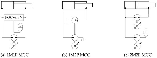
Figure 1.
Main MCC topologies [5].
Both 1M1P and 1M2P MCCs have been demonstrated to provide significantly higher energy efficiency than valve-controlled hydraulic cylinders, without compromising the control performance [12,13,14,15]. However, these topologies are unsuitable for remote installations, which are particularly beneficial for large cranes [16]. The reason is that 1M1P and 1M2P MCCs cannot offer an efficient load-holding function in hose rupture situations when installed remotely. Furthermore, 1M1P MCCs suffer from the pump mode oscillation issue when using two pilot-operated check valves (POCVs) or an inverse shuttle valve (ISV) to compensate for the cylinder differential flow [17]. Although it is possible to mitigate the pump mode oscillation and enable remote deployment by introducing additional control elements in 1M1P MCCs, this approach results in decreased system energy efficiency [18]. Additionally, the widespread application of 1M2P MCCs is constrained by the requirement for the pump displacements to align with the cylinder area ratio.
The inherent limitations of 1M1P and 1M2P MCCs can be effectively mitigated in a 2M2P MCC. This system directly manages the cylinder differential flow by employing a secondary hydraulic pump driven by a secondary electric servo motor. This approach eliminates the requirement for two POCVs or an ISV, thereby removing pump mode oscillations [19]. With the utilization of two electric servo motors, which offer two degrees of control freedom, 2M2P MCCs do not require a strict matching of pump displacements to the cylinder area ratio. Furthermore, these two control degrees enable simultaneous control of both the cylinder position and pressure, making 2M2P MCC an attractive option for applications such as injection molding machines [20,21,22] and knuckle boom cranes [23,24].
When applied in knuckle boom cranes, 2M2P MCCs need to operate in all four quadrants while also providing a load-holding function. Ideally, this load-holding function should not cause energy losses and effectively manage scenarios such as standstill commands, power outages, and hose ruptures. A 2M2P MCC, featuring an energy-efficient load-holding function for standstill commands and power outages, is demonstrated in [23]. Additionally, another study explores the same load-holding function in a 1M1P MCC, particularly in managing the hose rupture situation [18]. Achieving four-quadrant operation in hydraulic cylinder drive systems is essential as it is an industry requirement and serves as a prerequisite for energy regeneration. The current state of experimental verification for 2M2P MCCs applied in crane operations has predominantly concentrated on their two-quadrant functionality [24]. However, a critical gap exists in the literature regarding experimental validations encompassing both four-quadrant operation and load-holding function for a 2M2P MCC.
This paper addresses this gap by implementing a 2M2P MCC prototype, which has an energy-efficient load-holding function, on the knuckle cylinder of a knuckle boom crane. The main objective is to examine its operational and load-holding performance across all four quadrants.
2. Proposed System
The hydraulic schematic of the proposed 2M2P MCC is depicted in Figure 2a. This 2M2P MCC was also used in study [24]. It consists of two fixed-displacement pump/motor units known as the main unit () and the secondary unit (). These are operated by two electric servo motors, identified as the main electric servo motor/generator unit () and the secondary electric servo motor/generator unit (). Both and serve as the control elements in this system.
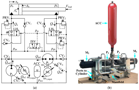
Figure 2.
The proposed 2M2P MCC. (a) System architecture of the 2M2P MCC. (b) 2M2P MCC drive system prototype.
The system inputs are represented by the velocity inputs ( and ) of and . The variables and represent the shaft velocities. A low-pressure accumulator (ACC) serves as the pressurized reservoir, maintaining 3 bar to supply the volumetric difference between the cylinder’s rod side and bore side, and to the pumps during suction to prevent cavitation. The external leakage lines of the pumps are linked to the ACC via two check valves ( and ). Two 2/2 normally closed load-holding valves ( and ) are manipulated by the minimum cylinder pressure signal (). The cracking pressure of and is 10 bar.
The signal is determined by the ISV, which switches its direction in response to the bore-side pump pressure and the rod-side pump pressure . Two check valves ( and ) are installed in parallel with the load-holding valves for an improved system response. Three pressure relief valves (, , and ) are integrated to limit the maximum pressure in the system. Three check valves (, , and ) are employed to ensure that the line pressures never become smaller than . The proposed 2M2P MCC is characterized by two distinct modes: the operation mode and the load-holding mode. During the operation mode, the pressure is regulated to remain over 10 bar, which opens and , allowing for the piston position () to be adjusted based on the command signal. Conversely, in the load-holding mode, is controlled to stay below 10 bar, causing and to close, thereby maintaining the cylinder piston in a stationary position.
The prototype of the proposed 2M2P MCC drive system is shown in Figure 2b. Table 1 lists the major components used in the 2M2P MCC prototype along with their respective parameters obtained from the manufacturers.

Table 1.
Major Components in 2M2P MCC.
3. Experimental Analysis
3.1. Experimental Setup
As depicted in Figure 3, the experiments are carried out on a knuckle boom crane featuring the 2M2P MCC drive system prototype connected to the knuckle cylinder. A payload is suspended from the tip of the knuckle boom. The position of the main cylinder remains fixed, resulting in a stationary main boom.
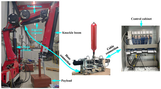
Figure 3.
Experimental setup: a knuckle boom crane, a 2M2P MCC prototype, and a control cabinet.
As the knuckle cylinder drives the knuckle boom and the payload, the 2M2P MCC (formed by the MCC drive system prototype and the knuckle cylinder) undergoes operation across all four quadrants, activating and deactivating the load-holding function as needed.
3.2. Four-Quadrant Operation Analysis
Figure 4 depicts the four-quadrant operation of the knuckle cylinder, showcasing its functionality in conjunction with the knuckle boom motion. In the figure, the red colour indicates the high chamber or line pressure, which holds the load. The yellow colour indicates the low chamber or line pressure, which is controlled by to stay above 10 bar so that the load holding valves remain open and cavitation is avoided with a certain margin. The green colour indicates the accumulator pressure, which is 3 bar. The blue dashed line on the crane icon denotes the neutral position, where no load force is applied to the knuckle cylinder. Gravity g acts downward. The first to the fourth quadrant are represented as , , , and .
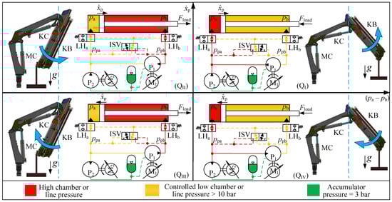
Figure 4.
Demonstration of the knuckle cylinder (KC) in four-quadrant operations.
In , the knuckle boom (KB in the figure) resides to the right of the neutral position and exhibits counterclockwise movement, indicated by the blue arrow. The piston is moving to the right (extending). In this case, due to the combined effects of the payload and the knuckle boom’s weight, the cylinder load force () directs towards the left, opposing the motion of the cylinder. Therefore, the cylinder bore side pressure () is higher than the cylinder rod side pressure (). The nominal speed of and are linked to the reference speed of the cylinder piston, . However, the speed of is continuously adjusted around its nominal value to ensure that the pump pressure on the rod side () is neither too low ( speeds down) nor too high ( speeds up). Effectively, controls the motion and controls the low pressure in the cylinder. This pattern is repeated for the other three quadrants. Also, the nominal speed of the pumps are the same in all four quadrants. For , it is . For , it is . However, the sign changes with , which is positive when extracting ( and ) and negative when retracting ( and ). In both and are motoring.
In , the knuckle boom is on the left side of the neutral position and exhibits counterclockwise movement. The piston is moving to the right (extending). In this case, due to the combined effects of the payload and the knuckle boom’s weight, directs towards the right, assisting the motion of the cylinder and is higher than . As in , the low pressure, here , is controlled by adjusting the speed of , speeding up if goes below the reference pressure and slowing down if goes above the reference pressure. As in , is subtracting liquid from the accumulator and is motoring while is generating.
In , the knuckle boom is on the left side of the neutral position and exhibits a clockwise movement. The piston is moving to the left (retracting). In this case, due to the combined effects of the payload and the knuckle boom’s weight, directs towards the right, opposing the motion of the cylinder and is higher than . In this quadrant, is adding liquid to the accumulator and is controlling . is motoring and is generating.
In , the knuckle boom is on the right side of the neutral position and exhibits clockwise movement. The piston is moving to the left (retracting). In this case, due to the combined effects of the payload and the knuckle boom’s weight, directs towards the left, assisting the motion of the cylinder and is lower than . In this quadrant, is adding liquid to the accumulator and is controlling . Both and are generating.
It is noteworthy that during the operation of the knuckle cylinder within the transitional regions between and or between and , specifically when the knuckle boom moves across the neutral position, the controlled pressure dynamically switches between and . As a result, the magnitudes of and shall intersect at the switching point. It should be noted that the switching point does not occur exactly at the neutral position but rather slightly around it. According to the force equilibrium of the cylinder at the neutral position, the bore side pressure and the rod side pressure can never be equal because the cylinder area ratio is 0.56. However, as the cylinder pressures are low and close to each other at the neutral position, the deviation between the neutral position and the switching point has no significant influence.
3.3. Passive Load-Holding Function in Four Quadrants
In Figure 5, the status and motions of all components when the load-holding function is activated in all four quadrants are depicted. The blue color represents the low chamber or line pressure. As the load-holding valve cracking pressure is set at 10 bar, the pressure marked in blue is lower than 10 bar but higher than the accumulator pressure. The system status and component motions exhibit distinct similarities when the load-holding function is engaged in both and , as well as in and .
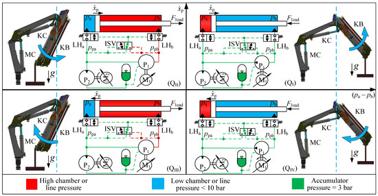
Figure 5.
Demonstration of triggered load-holding functions in four quadrants.
Consequently, the load-holding function activated in and is denoted as bore-side load holding, while that in and is referred to as rod-side load holding. It should be noted that in the figure only represents the piston velocity before the load-holding function is triggered.
In the bore-side load holding, the load-holding function is activated by pumping the rod side oil to the accumulator through and , effectively reducing below 10 bar. Conversely, in the rod-side load holding, the load-holding function is activated by pumping the bore side oil to the accumulator solely through P2, leading to a pressure below 10 bar.
4. Control Algorithm
The control algorithm, originally proposed for 2M2P MCCs in [24], is employed in this study. This control algorithm is depicted in Figure 6. It comprises four distinct control loops, namely the position control loop, cylinder pressure control loop, load-holding control loop, and pressure level control loop. The outputs from these four control loops are strategically selected by the mode and inputs selection module in accordance with the explanations in Section 3.
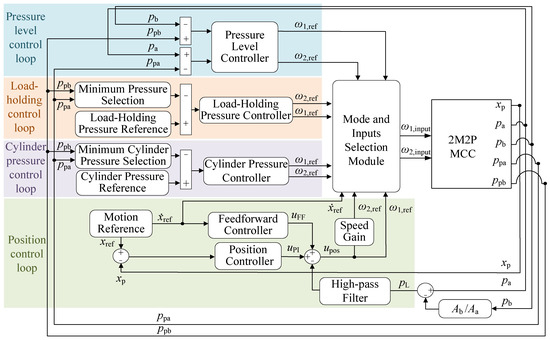
Figure 6.
Illustration of the control algorithm [24].
This approach ensures the realization of four-quadrant operation, passive load-holding functionality, and seamless transitions between these operational states. A thorough explanation of this control algorithm is available in [24]. This control algorithm is implemented and tuned on the experimental setup to facilitate the experiments. The proportional (P) and integral (I) controller gains in the four control loops are detailed in Table 2. The cylinder pressure reference is set to 15 bar. The load-holding pressure reference is set to 3 bar.
Table 2.
The proportional and integral gains in four control loops.
5. Results of Experimental Work
5.1. Reference Signals and Experiment Procedures
Cylinder position reference signals incorporating operation and load-holding function across four quadrants are required for the experiments. Figure 7 visually depicts a representative position reference signal that fulfills these criteria. Here, denotes the cylinder stroke end, and indicates the end of the experiment. This signal initiates with a rod-side load-holding period, featuring a position close to zero, followed by an extension operation in .
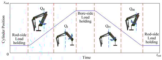
Figure 7.
The cylinder position ensuring that both types of load holding and all four quadrants are experienced.
Upon the knuckle boom crossing the neutral line, the knuckle cylinder operation transitions to . It continues to extend until the cylinder reaches a position close to , at which point it enters a bore-side load-holding period. Subsequently, the cylinder initiates retraction in . Following the passage of the knuckle boom across the neutral line, the cylinder operation shifts to . As the knuckle cylinder retracts to the original position, it enters a rod-side load-holding period, lasting until the end of the experiment.
Three distinct cases are considered in the experiment to thoroughly validate the four-quadrant operation and load-holding function of the proposed system. These three cases are described in Table 3. It should be noted that the prototype approaches its peak power limit in case three. The cylinder position reference signals in different cases, following the general rule illustrated in Figure 7, exhibit variations in stroke length and experiment time. The results described in the following subsections comprise the position reference (Ref) and feedback (FB), the position error, and the system pressures. In the figures, the light blue dotted lines separate different quadrants and load-holding periods. , , , and denote the first to fourth quadrants, respectively. The rod-side load holding and bore-side load holding are abbreviated as R-LH and B-LH, respectively.
Table 3.
Three cases in the experiment.
5.2. Case One
The cylinder position reference and feedback signals are depicted in Figure 8a. These signals exhibit a nearly perfect overlap indicating small tracking errors. The cylinder initiates with a period of rod-side load holding, proceeds to extend through and , followed by a bore-side load-holding phase. Subsequently, the cylinder retracts through and before returning to a rod-side load holding phase. The position tracking error for case one is depicted in Figure 8b. The maximum error, approximately −2.5 mm, occurs during the initiation of the cylinder’s extension in . Throughout the remaining duration of the experiment, especially the transitions between operation and load-holding phases, the tracking error consistently remains within the range of ±0.8 mm.
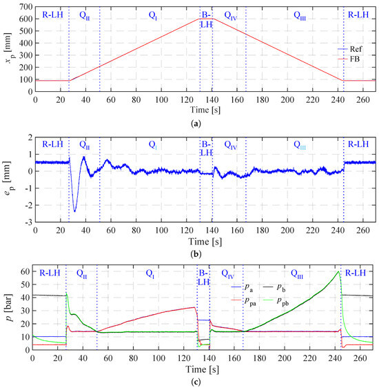
Figure 8.
Experimental results in case one. (a) Cylinder position reference and feedback signals in case one. (b) Position tracking error in case one. (c) System pressures in case one.
The bore-side cylinder pressure () and pump pressure (), along with the rod-side cylinder pressure () and pump pressure () in case one, are illustrated in Figure 8c. In the first rod-side load-holding phase, and are closed. holds the load and is about 41 bar. is around 10 bar, which is the cracking pressure of the load-holding valves. is controlled to the load-holding pressure reference (3 bar) because it is the pressure operating the load-holding valves. Upon the transition to , the and valves open, leading to equalization between and as well as and . In , precise control maintains around the cylinder pressure reference of 15 bar. As the cylinder extends within , a gradual descent in is observed. Upon the intersection of with , the cylinder operation transitions into , where assumes the role of the controlled minimum cylinder pressure, stabilized at 15 bar. As the cylinder enters the bore-side load-holding phase, where the activation of the load-holding pressure controller causes a rapid reduction of to 3 bar. Therefore, the load-holding valves promptly close. The bore-side cylinder pressure is, therefore, maintained at around 21 bar. Concurrently, a gradual decrease in to 3 bar ensues, attributed to pump leakage. Following the bore-side load-holding phase, the cylinder initiates retraction within . During this quadrant, is higher than and gradually declining. , as the minimum cylinder pressure, is controlled at 15 bar. As intersects with for the second time, the cylinder transitions into , with serving as the controlled minimum cylinder pressure, stabilized at 15 bar. Upon completing the retraction and returning to the starting position, the cylinder enters the second rod-side load-holding phase. Here, the load-holding pressure controller rapidly reduces to 3 bar, prompting the swift closure of the load-holding valves.
5.3. Case Two
In case two, a payload of 600 kg hangs on the crane tip, and the maximum cruising speed for both extending and retracting is maintained at 5 mm/s. The experimental results of case two are shown in Figure 9. Similar to case one, the cylinder, driving the knuckle boom, demonstrates effective tracking of the position reference signal across four quadrants and two load-holding phases, as illustrated in Figure 9a.
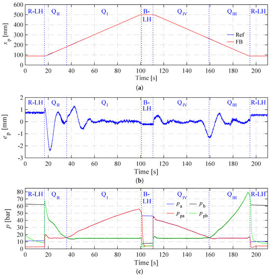
Figure 9.
Experimental results in case two. (a) Cylinder position reference and feedback signals in case two. (b) Position tracking error in case two. (c) System pressures in case two.
In Figure 9b, the maximum position tracking error (−2.5 mm) also occurs during the initiation of the cylinder’s extension in . However, in the remaining experiment period, the tracking error in case two exhibits greater amplitudes (±1.2 mm) and more noticeable fluctuations compared to case one. These fluctuations mainly occur at the transitions between and and between and . As demonstrated in Figure 9c, the system pressures in the second case show similar trends to those observed in case one as the cylinder operation moves through four quadrants and two load-holding phases. However, the pressure levels in case two are higher than those observed in case one. During the rod-side load-holding phase, is maintained at approximately 61 bar, while in the bore-side load-holding phase, is maintained at approximately 43 bar. The maximum system pressure of 80 bar is reached by the end of .
5.4. Case Three
In case three, the payload of 600 kg hanging on the crane tip is retained, and the maximum cruising speed for both extending and retracting is increased to 15 mm/s. It is important to note that the maximum power output of the prototype in case three is close to the rated power. The experimental results of case three are shown in Figure 10. In case three, as depicted in Figure 10a, the cylinder position can effectively track the reference signal across four quadrants and two load-holding phases. According to Figure 10b, the position tracking errors are within ±2 mm in and , and ±1 mm in and .
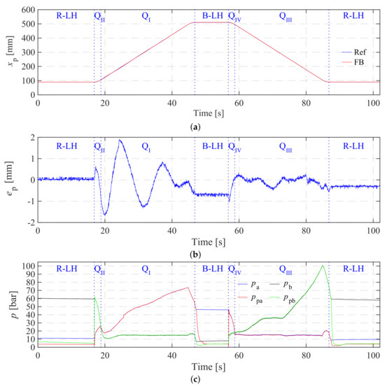
Figure 10.
Experimental results in case three. (a) Cylinder position reference and feedback signals in case three. (b) Position tracking error in case three. (c) System pressures in case three.
The system pressures in case three are plotted in Figure 10c. Because the payload used in case three is the same as case two, the system pressures during load-holding phases in case three are almost the same as those in case two. The maximum system pressure of 100 bar is reached by the end of . When the cylinder operates across four quadrants in case three, the system pressures increase or decrease quickly due to the faster motion. Therefore, and in case three last a much shorter period than those in case one and case two.
6. Discussion
In this study, three test cases, featuring some challenging and representative elements similar to ordinary use, are conducted to verify the system’s capability of operating across four quadrants and two load-holding phases. Across these cases, the system output power is increased by adding a 600 kg payload and elevating the maximum speed. Analysis of the position tracking error plots indicates a degradation in position tracking performance from case one to case three. This is expected, given that the output power increases progressively from case one to case three. However, it is worth noting that the tracking error in all three cases remains within a satisfactory range, with the maximum tracking error accounting for approximately 0.6% of the total cylinder strokes in the experiments.
The minimum cylinder pressure in the three cases are effectively controlled around the reference pressure. Moreover, the successful crossing of the low and high pressures in all three cases demonstrates the switching function in the controllers.
As analyzed in Section 3.3, the system statuses when the load-holding function is triggered in and are nearly identical. The same applies to the load-holding function triggered in and . Therefore, only the load-holding functions triggered in and have been verified.
7. Conclusions
A critical gap exists in the literature regarding experimental validations encompassing both four-quadrant operation and load-holding function for a 2M2P MCC. This paper bridges this gap through the following key aspects:
- The system status and component motions of the proposed 2M2P MCC are comprehensively analyzed.
- A specialized experimental setup is constructed, comprising a knuckle boom crane and a 2M2P MCC prototype.
- A position reference involving four-quadrant operation and two types of load holding is developed.
- Experiments are conducted across three cases, with satisfactory position tracking performance and seamless pressure intersection during transitions between different quadrants of operation.
In conclusion, the proposed 2M2P MCC demonstrates effective operation and a load-holding function across all four quadrants. This research contributes significantly to the understanding and practical implementation of 2M2P MCCs in various industrial applications.
Author Contributions
Conceptualization, W.Z.; methodology, W.Z.; software, W.Z.; investigation, W.Z.; data curation, W.Z.; writing—original draft preparation, W.Z.; writing—review and editing, W.Z., M.K.E., and M.R.H.; supervision, M.K.E., M.R.H., and T.O.A.; funding acquisition, M.K.E. All authors have read and agreed to the published version of the manuscript.
Funding
This research was funded by the Research Council of Norway, SFI Offshore Mechatronics, project number 237896/O30. The APC was funded by the University of Agder.
Data Availability Statement
The data supporting this study are available upon request. Please contact the corresponding author for access.
Acknowledgments
We would like to express our sincere gratitude to the following lab engineers for their invaluable assistance in building and testing the experimental setup: Jan Andreas Holm, Harald Sauvik, and Jan Christian Bjerke Strandene. Their expertise and willingness to help were instrumental in the successful completion of this project.
Conflicts of Interest
The authors declare no conflicts of interest.
References
- Zimmerman, J.D.; Pelosi, M.; Williamson, C.A.; Ivantysynova, M. Energy Consumption of an LS Excavator Hydraulic System. In Proceedings of the ASME 2007 International Mechanical Engineering Congress and Exposition, Seattle, WA, USA, 11–15 November 2007; pp. 117–126. [Google Scholar]
- Quan, Z.; Quan, L.; Zhang, J. Review of energy efficient direct pump controlled cylinder electro-hydraulic technology. Renew. Sustain. Energy Rev. 2014, 35, 336–346. [Google Scholar] [CrossRef]
- Ketelsen, S.; Padovani, D.; Andersen, T.O.; Ebbesen, M.K.; Schmidt, L. Classification and Review of Pump-Controlled Differential Cylinder Drives. Energies 2019, 12, 1293. [Google Scholar] [CrossRef]
- Fassbender, D.; Zakharov, V.; Minav, T. Utilization of electric prime movers in hydraulic heavy-duty-mobile-machine implement systems. Autom. Constr. 2021, 132, 103964. [Google Scholar] [CrossRef]
- Zhao, W.; Ebbesen, M.K.; Andersen, T.O. Identifying The Future Research Trend for Using Speed-Controlled Hydraulic Cylinders in Offshore Applications through Literature Survey. In Proceedings of the 2022 IEEE Global Fluid Power Society PhD Symposium (Presented), Naples, Italy, 12–14 October 2022. [Google Scholar]
- Ivantysynova, M. The swash plate machine for displacement control unit with great development potentiality. In Proceedings of the First IFK, Aachen, Germany, 18–23 May 1998. [Google Scholar]
- Rahmfeld, R.; Ivantysynova, M. Displacement controlled linear actuator with differential cylinder—A way to save primary energy in mobile machines. In Proceedings of the Fifth International Conference on Fluid Power Transmission and Control, Hangzhou, China, 3–5 April 2001. [Google Scholar]
- Rahmfeld, R.; Ivantysynova, M. Energy Saving Hydraulic Displacement Controlled Linear Actuators in Industry Applications and Mobile Machine Systems. In Proceedings of the Fourth International Symposium on Linear Drives for Industry Applications, Birmingham, UK, 8–10 September 2003. [Google Scholar]
- Zimmerman, J.; Busquets, E.; Ivantysynova, M. 40% fuel savings by displacement control leads to lower working temperatures—A simulation study and measurements. In Proceedings of the IFPE, International Exposition for Power Transmission and Technical Conference, 2011, the 52nd NCFP, National Conference on Fluid Power, Las Vegas, NV, USA, 23–25 March 2011; National Fluid Power Association: Milwaukee, WI, USA, 2011; p. 1081. [Google Scholar]
- Helduser, S. Electric-hydrostatic drive—An innovative energy-saving power and motion control system. Proc. Inst. Mech. Eng. Part I J. Syst. Control Eng. 1999, 213, 427–437. [Google Scholar] [CrossRef]
- Rydberg, K.E. Energy Efficient Hydraulics—System solutions for loss minimization. In Proceedings of the National Conference on Fluid Power, Linköping, Sweden, 14–16 December 2015. [Google Scholar]
- Hagen, D.; Padovani, D.; Choux, M. A comparison study of a novel self-contained electro-hydraulic cylinder versus a conventional valve-controlled actuator—Part 2: Energy efficiency. Actuators 2019, 8, 78. [Google Scholar] [CrossRef]
- Hagen, D.; Padovani, D.; Choux, M. A Comparison Study of a Novel Self-Contained Electro-Hydraulic Cylinder versus a Conventional Valve-Controlled Actuator—Part 1: Motion Control. Actuators 2019, 8, 79. [Google Scholar] [CrossRef]
- Zhang, S.; Minav, T.; Pietola, M. Decentralized Hydraulics for Micro Excavator. In Proceedings of the 15th Scandinavian International Conference on Fluid Power, Linköping, Sweden, 7–9 June 2017; pp. 187–195. [Google Scholar]
- Ketelsen, S.; Schmidt, L.; Donkov, V.H.; Andersen, T.O. Energy saving potential in knuckle boom cranes using a novel pump controlled cylinder drive. Model. Identif. Control (Online) 2018, 39, 73–89. [Google Scholar] [CrossRef]
- Zhao, W.; Bhola, M. Comparing Compact and Remote Deployments of a Speed-Controlled Cylinder Drive Unit on an Offshore Knuckle Boom Crane. In Proceedings of the 18th Scandinavian International Conference on Fluid Power, Tampere, Finland, 30 May–1 June 2023; pp. 518–533. [Google Scholar]
- Williamson, C.; Ivantysynova, M. Pump Mode Prediction for Four-Quadrant Velocity Control of Valueless Hydraulic Actuators. In Proceedings of the JFPS International Symposium on Fluid Power, Toyama, Japan, 15–18 September 2008; pp. 323–328. [Google Scholar]
- Zhao, W.; Ebbesen, M.K.; Hansen, M.R.; Andersen, T.O. Enabling Passive Load-Holding Function and System Pressures Control in a One-Motor-One-Pump Motor-Controlled Hydraulic Cylinder: Simulation Study. Energies 2024, 17, 2484. [Google Scholar] [CrossRef]
- Kärnell, S.; Ericson, L. Control of an Asymmetric Cylinder with Two Individually Controlled Pump/Motors. In Proceedings of the ASME/BATH 2023 Symposium on Fluid Power and Motion Control, Sarasota, FL, USA, 16–18 October 2023. [Google Scholar]
- Helduser, S. Electric-Hydrostatic Drive Systems and Their Application in Injection Moulding Machines. Proc. JFPS Int. Symp. Fluid Power 1999, 1999, 261–266. [Google Scholar] [CrossRef][Green Version]
- Cho, S.H.; Räcklebe, S.; Helduser, S. Position tracking control of a clamp-cylinder for energy-saving injection moulding machines with electric-hydrostatic drives. Proc. Inst. Mech. Eng. Part I J. Syst. Control Eng. 2009, 223, 479–491. [Google Scholar] [CrossRef]
- Hertz, R.A.; Therkelsen, O.; Kristiansen, S.; Christensen, J.K.; Helver, C.E.; Schmidt, L. Practical Implementation of Secondary Control Principles in an Electro-Hydraulic Speed-Variable Drive Applied to an Injection Moulding Machine. In Proceedings of the ASME/BATH 2023 Symposium on Fluid Power and Motion Control, Sarasota, FL, USA, 16–18 October 2023. [Google Scholar]
- Ketelsen, S.; Andersen, T.O.; Ebbesen, M.K.; Schmidt, L. A Self-Contained Cylinder Drive with Indirectly Controlled Hydraulic Lock. Model. Identif. Control. A Nor. Res. Bull. 2020, 41, 185–205. [Google Scholar] [CrossRef]
- Zhao, W.; Bhola, M.; Ebbesen, M.K.; Andersen, T.O. A Novel Control Design for Realizing Passive Load-Holding Function on a Two-Motor-Two-Pump Motor-Controlled Hydraulic Cylinder. Model. Identif. Control 2023, 44, 125–139. [Google Scholar] [CrossRef]
Disclaimer/Publisher’s Note: The statements, opinions and data contained in all publications are solely those of the individual author(s) and contributor(s) and not of MDPI and/or the editor(s). MDPI and/or the editor(s) disclaim responsibility for any injury to people or property resulting from any ideas, methods, instructions or products referred to in the content. |
© 2024 by the authors. Licensee MDPI, Basel, Switzerland. This article is an open access article distributed under the terms and conditions of the Creative Commons Attribution (CC BY) license (https://creativecommons.org/licenses/by/4.0/).