Article

Research on Vibration Reduction Characteristics of High-Speed Elevator with Rolling Guide Shoes Based on Hydraulic Damping Actuator

1
School of Mechatronics and Energy Engineering, NingboTech University, Ningbo 315100, China
2
College of Mechanical and Electrical Engineering, China Jiliang University, Hangzhou 310018, China
*
Author to whom correspondence should be addressed.
Actuators 2024, 13(9), 356; https://doi.org/10.3390/act13090356
Submission received: 25 June 2024 / Revised: 1 September 2024 / Accepted: 10 September 2024 / Published: 12 September 2024

Abstract

:
This paper endeavors to tackle the issue of horizontal vibrations encountered in high-speed and ultra-high-speed elevator cabins during operation. Given the limitations of traditional passive-control guide shoes in effectively mitigating these vibrations and the complexity and cost associated with active control systems, a novel approach involving passive-control rolling guide shoes (PCRGS) integrated with hydraulic damping is explored. The PCRGS incorporates a hydraulic actuator and hydraulic damping, which can be modeled by a mechanical and hydraulic co-simulation model using AMESim2020 software. The simulation reveals a substantial reduction in cabin vibrations equipped with PCRGS. Specifically, under pulse excitation, the reduction ranges from 26.2% to 27.5%; under white noise excitation, it varies between 14.3% and 17.1%; and under sine wave excitation, the reduction spans 21.2% to 24.1%. Notably, the system meets the stringent ‘Excellent’ (<=0.07 m/s2) performance criteria under sine wave excitation at lower frequencies, signifying its high effectiveness. These findings not only underscore the potential of hydraulic passive-control guide shoes in mitigating elevator vibrations but also provide invaluable guidance for their further development and refinement.

1. Introduction

In recent decades, the accelerated pace of urbanization has led to a profound surge in the construction of towering skyscrapers [1], necessitating significant advancements in elevator technology to cater to the escalating heights of these structures. Chief among these advancements are the prioritization of enhancing elevator operational safety and optimizing passenger comfort, particularly in the realm of high-speed and ultra-high-speed elevators, which are categorized based on their operational velocities (low-speed v ≤ 1.0 m/s, medium-speed 1.0 m/s < v ≤ 2.5 m/s, high-speed 2.5 m/s < v ≤ 6.0 m/s, and ultra-high-speed v > 6.0 m/s) [2]. Extant research underscores the fact that as elevator speeds escalate, the horizontal vibrations experienced by elevator cabins intensify markedly, heightening the likelihood of abnormal oscillations [3]. This phenomenon, coupled with the continuous exposure to high-frequency and substantial horizontal vibrations, can lead to accelerated wear and tear of critical elevator components, thereby posing a significant threat to the overall safety and integrity of the elevator system [4,5,6]. Consequently, the mitigation of horizontal vibrations during the operation of high-speed elevators has emerged as a paramount area of investigation for elevator manufacturers worldwide, underscoring the urgency of developing innovative solutions to ensure smoother, safer, and more comfortable rides.
The guide shoes hold a pivotal position within the elevator operational system. They are securely attached to the car frame and maintain direct contact with the guide rail. The primary function of the guide shoes is to facilitate the accurate and uninterrupted vertical movement of the elevator along the guide rail. Additionally, they serve as a critical component in mitigating vibrations that may be transmitted from the guide rail to the car frame and the cabin interior. By effectively dampening these vibrations, the guide shoes play an essential role in ensuring the stability, comfort, and paramount safety of elevator operations [7,8].
Currently, the conventional passive-control rolling guide shoes exhibit a notable insufficiency in fulfilling the rigorous vibration attenuation requirements of high-speed and ultra-high-speed elevators. This limitation arises from their reliance on passive vibration suppression strategies and the inherent constraints of spring-rubber damping mechanisms, which offer limited damping capacity. The simplistic mass-spring-damping architecture employed in these traditional guide shoes has hindered comprehensive research endeavors in this field, leading to a scarcity of comprehensive literature. Consequently, the optimization of spring and damping parameters largely depends on the expertise and empirical knowledge of technicians from diverse elevator manufacturers, further limiting the accessibility of standardized technical references. In contrast, active-control rolling guide shoes have emerged as a prevalent solution in high-speed and ultra-high-speed elevator systems, due to their integration of active control actuators and to the utilization of advanced control algorithms. Extensive research has been conducted on the intricate designs and operational principles of active actuators within these guide shoes alongside the development and refinement of associated control strategies [9,10,11,12]. However, the adoption of active-control rolling guide shoes is accompanied by substantial financial implications, including heightened initial costs and maintenance expenses, necessitating a meticulous cost-benefit analysis for their widespread implementation.
The objective of this research endeavor is to deviate from the conventional focus on traditional rolling guide shoes reliant on springs and rubber damping as well as the intricate and financially burdensome active control alternatives. Instead, this study introduces an innovative paradigm that incorporates hydraulic throttling as a damper, building upon the established foundation of rolling guide shoes. This approach aims to augment the vibration attenuation capabilities of the guide shoes, ultimately enhancing the operational stability of and passenger comfort in high-speed and ultra-high-speed elevators while maintaining cost-effectiveness. The technology roadmap of the paper concerning rolling guide shoes is shown Figure 1. And the structural and methodological framework of this paper is meticulously outlined as follows: Initially, a rigorous analysis and calculation of elevator standards and operational parameters are conducted to derive the precise characteristics of the guide rail unevenness signal, which serves as the primary excitation source for horizontal vibrations within the elevator car system. Subsequently, the structure and operational principles of the proposed passive-control rolling guide shoes featuring hydraulic damping are elaborated upon, drawing upon the foundational concepts outlined in the Chinese patent titled “Passive Control Elevator Rolling Guide Shoes with Hydraulic Damping” [13]. Furthermore, to facilitate a comprehensive comparison, two-degree-of-freedom vibration mathematical models and AMESim2020 simulation models are developed for both the passive-control rolling guide shoes with hydraulic damping and their traditional counterparts. Finally, the uneven excitation signal of the guide rail, derived from our analysis and calculations, serves as the input signal in the AMESim2020 simulations. These simulations generate vibration acceleration data within the elevator car, enabling a quantitative assessment and comparison of the performance of the passive-control rolling guide shoes with hydraulic damping vis-à-vis the traditional passive-control rolling guide shoes.

2. Overall Analysis of Elevator Horizontal Vibration

2.1. Overview of Elevator and Guide Shoes

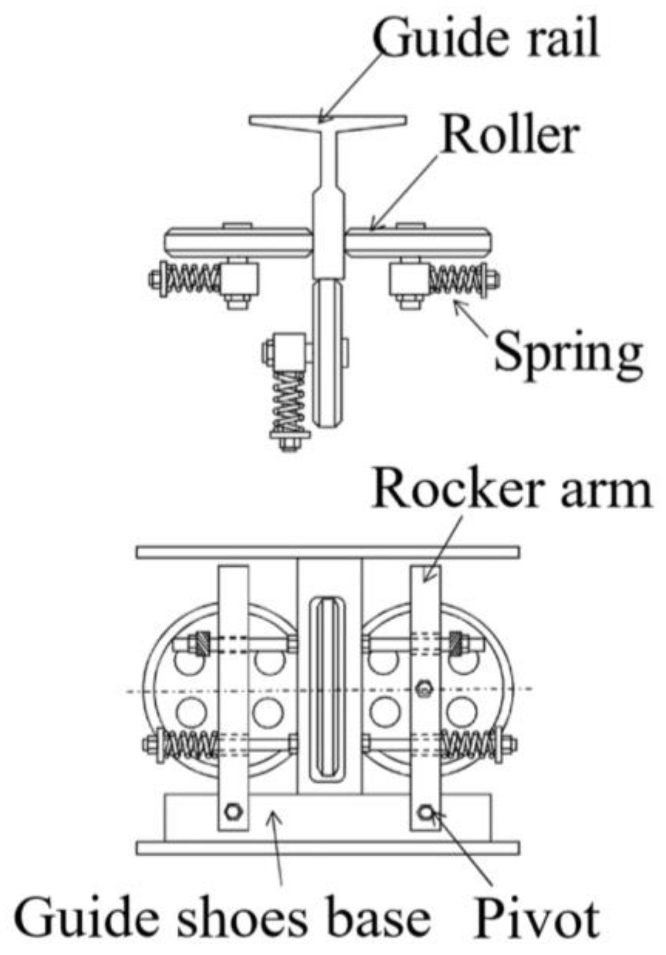
Figure 2 illustrates the schematic of the elevator car and its guidance system. The elevator car primarily consists of a cabin and a frame. Isolation rubber components are situated between the cabin and the frame, and rolling guide shoes are positioned at the four corners of the frame. Figure 3 presents a schematic of a rolling guide shoe. The system features three rubber rollers, each supported by a rocker arm and a pre-tensioning spring, and each is in contact with the guide rail surface.
Guide shoes are classified into two types: sliding guide shoes and rolling guide shoes. Sliding guide shoes are primarily utilized in low-speed elevators (v ≤ 1.0 m/s), whereas rolling guide shoes utilize rolling friction instead of sliding friction, which significantly reduces vibration and enhances ride comfort. Consequently, rolling guide shoes are typically employed in elevators operating at medium speeds and above (v > 1.0 m/s). Rolling guide shoes are divided into two types: passive-control rolling guide shoes and active-control rolling guide shoes, based on their vibration reduction principles. The vibration reduction of passive-control rolling guide shoes is achieved through a spring and damping mechanism. Active-control rolling guide shoes achieve vibration reduction through the installation of sensors and an active actuator. These components generate forces and moments to counteract the external excitation of the elevator car system, thus balancing external force interference and achieving active vibration reduction [14,15]. Consequently, passengers experience a smoother and more comfortable ride. Due to its exceptional vibration reduction capacity, it is frequently used in ultra-high-speed elevators. The structure and control process of active-control guide shoes are intricate, leading to high construction and maintenance costs [16,17].

2.2. Evaluation Standards for Elevator Vibration

According to the elevator technical standard GB/T 10058-2009 “Specification for Electric Lifts,” the evaluation of elevator running quality is based on measuring floor acceleration, specifically the peak or peak-to-peak values in the horizontal direction. Passenger elevator cabin acceleration must meet stringent standards, covering vertical (Z axis) and horizontal (X and Y axis) vibrations. The maximum horizontal vibration acceleration of the elevator must not exceed 0.2 m/s2 [18]. Table 1 provides the specifications for horizontal acceleration across different elevator grades. According to the Chinese technical standard GB/T 24474.1-2020: “Measurement of Ride Quality–Part 1: Lifts (Elevators),” the horizontal acceleration examined in this study pertains to the Y direction, which is the left-to-right direction of the elevator cabin (i.e., parallel to the cabin door) [19].

2.3. Excitation Source for Elevator Horizontal Vibration

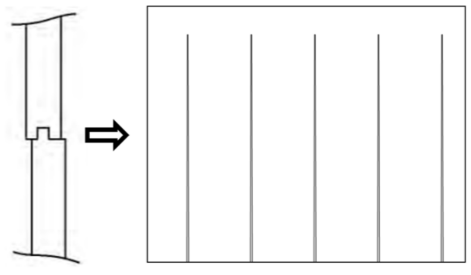
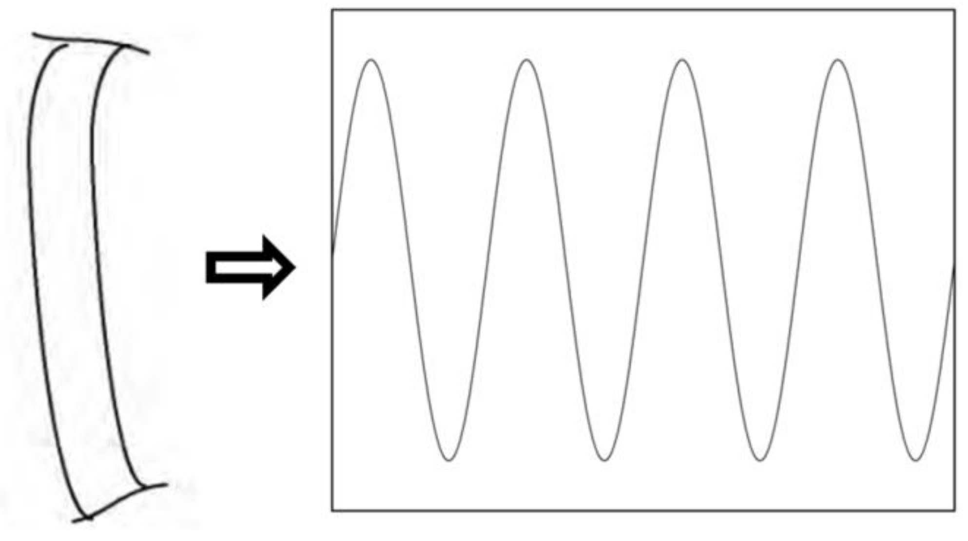
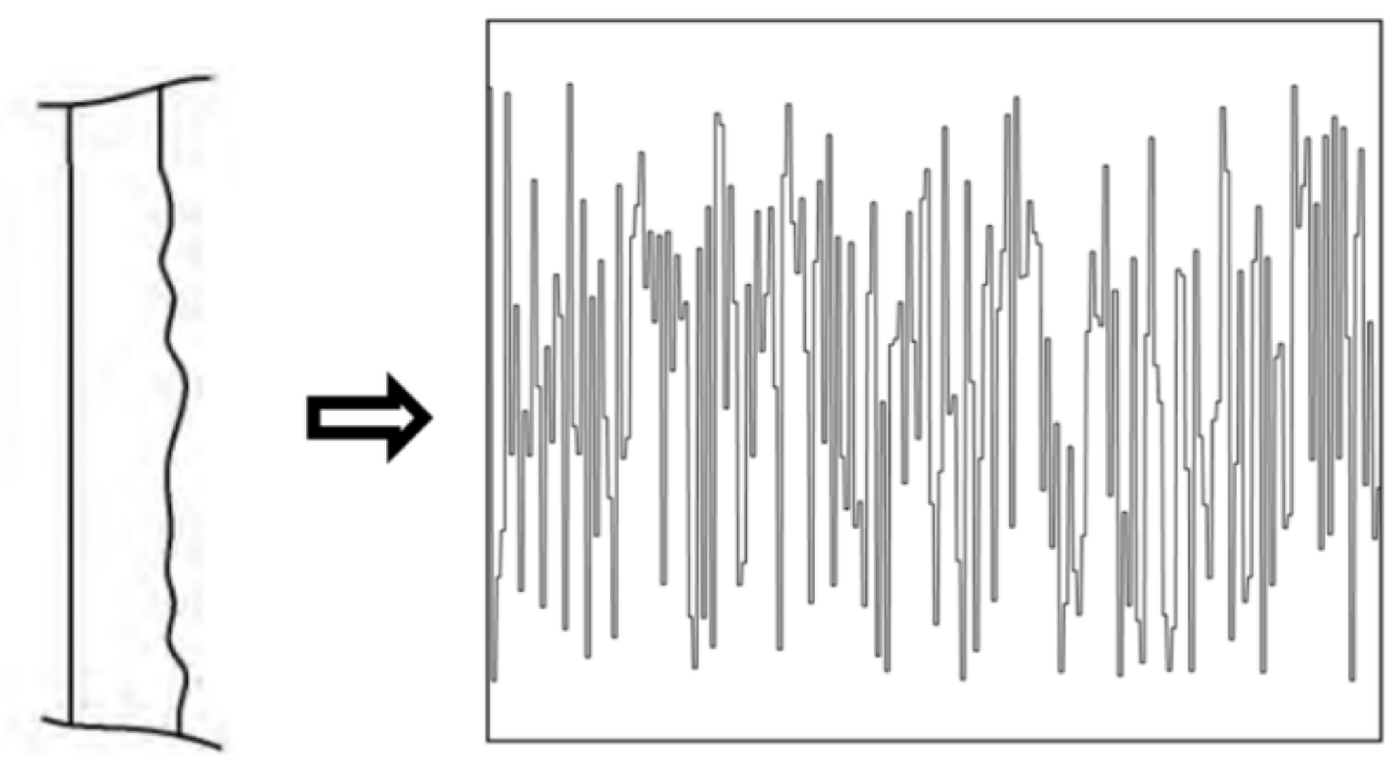
Numerous studies have shown that guide rail joints, bending, and surface wear are the primary sources of horizontal vibration in the elevator cabin, with corresponding vibration signals being pulse, sine wave, and white noise signals [20]. Therefore, the pulse, sine wave, and white noise signals will be used as vibration excitation signals for simulation in this paper, as illustrated in Figure 4, Figure 5 and Figure 6, respectively.
According to elevator technical standards [19,21], the allowable maximum amplitude for joint step and bending of the guide rail is 2 mm, and is 0.75 mm for surface wear. The length of a single guide rail in the elevator is 5 m. The pulse signal frequency is calculated based on the elevator’s running speed and the length of a single guide rail. The frequency of the sine wave signal is determined by the elevator’s running speed and the total length of the multiple guide rails that form the cycle. This paper focuses on an ultra-high-speed elevator with a running speed of 8 m/s. Table 2 provides the calculated typical excitation from the guide rail.

3. Working Principles

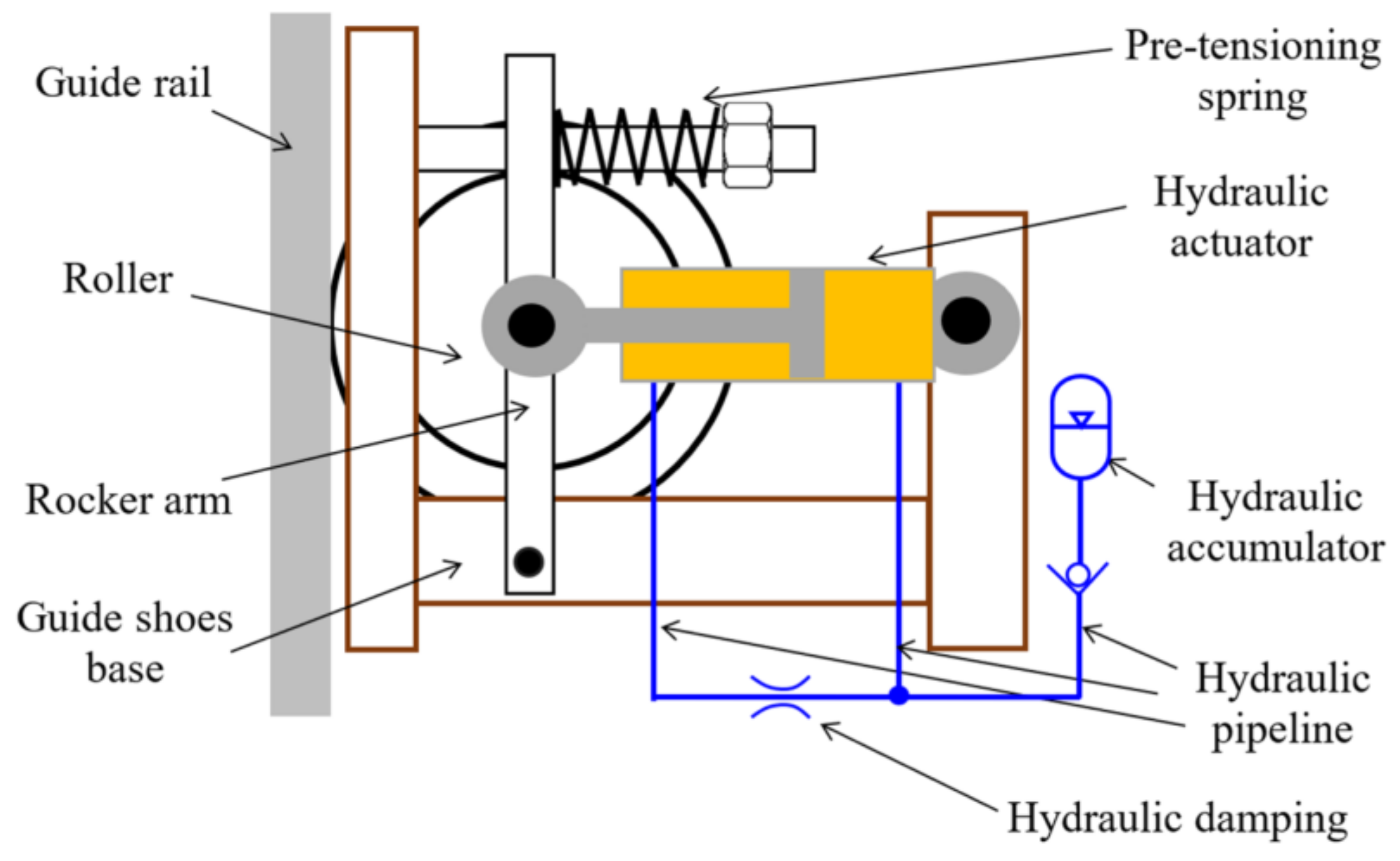
The structural principle of rolling guide shoes with hydraulic damping is depicted in Figure 7. It does not require external real-time control and energy input; therefore, it is essentially a passive-control rolling guide shoe. The structural composition and working principle are consistent with those described in the patent “Passive Control Elevator Rolling Guide Shoes with Hydraulic Damping” [13], as outlined below.
(1)
The system primarily comprises mechanical and hydraulic components. The mechanical components primarily include the guide shoes base, roller, rocker arm, and pre-tensioning spring. The hydraulic components primarily consist of the hydraulic actuator, hydraulic damping system, hydraulic pipelines, and hydraulic accumulator. Among these components, the rolling guide shoes are securely attached to the elevator cabin via the guide shoes’ base. The outer circular surface of the roller contacts the guide rail directly, while the roller’s center is hinged to the rocker arm. The lower end of the rocker arm is hinged to the guide shoes’ base, whereas the upper end presses the roller onto the guide rail using a pre-tensioning spring, thus ensuring a snug fit with the guide rail. The hydraulic damping component is situated between the rocker arm and the guide shoes’ base.
(2)
The hydraulic actuator functions as a support component for the roller. When the roller experiences uneven excitation from the guide rail, it induces lateral oscillation of the rocker arm. Consequently, the piston rod of the hydraulic actuator extends or retracts, converting the vibrational energy of the roller into pressure energy within the hydraulic actuator.
(3)
During the extension and retraction of the piston rod, the hydraulic oil within the actuator circulates between the left and right chambers. The oil also passes through the hydraulic damping orifice, which helps to suppress and dissipate the pressure through hydraulic damping. This process ultimately serves to reduce the system’s overall energy and dynamic response.
(4)
The hydraulic accumulator is linked to the oil chamber and pipeline at the end of the cylinder adjacent to the hydraulic cylinder. It absorbs hydraulic pressure impacts in the pipeline, thereby further enhancing the vibration reduction performance of the rolling guide shoes.

4. Simulations

4.1. Simulation Models

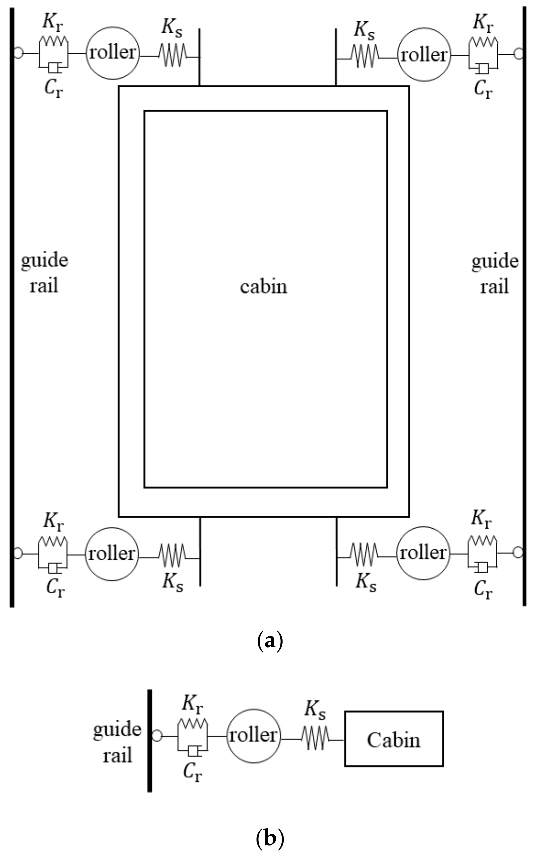
Before establishing the simulation model of rolling guide shoes with hydraulic damping, the two-degree-of-freedom horizontal vibration model of the elevator car and the guidance system equipped with traditional rolling guide shoes, as shown in Figure 8a, was initially developed, corresponding to Figure 2. The rollers of the rolling guide shoes are considered to be spring-damping systems [16,20], with a total of four acting on the upper, lower, left, and right sections of the cabin. The two-degree-of-freedom horizontal vibration model of a single traditional rolling guide shoe acting on the elevator car is illustrated in Figure 8b.
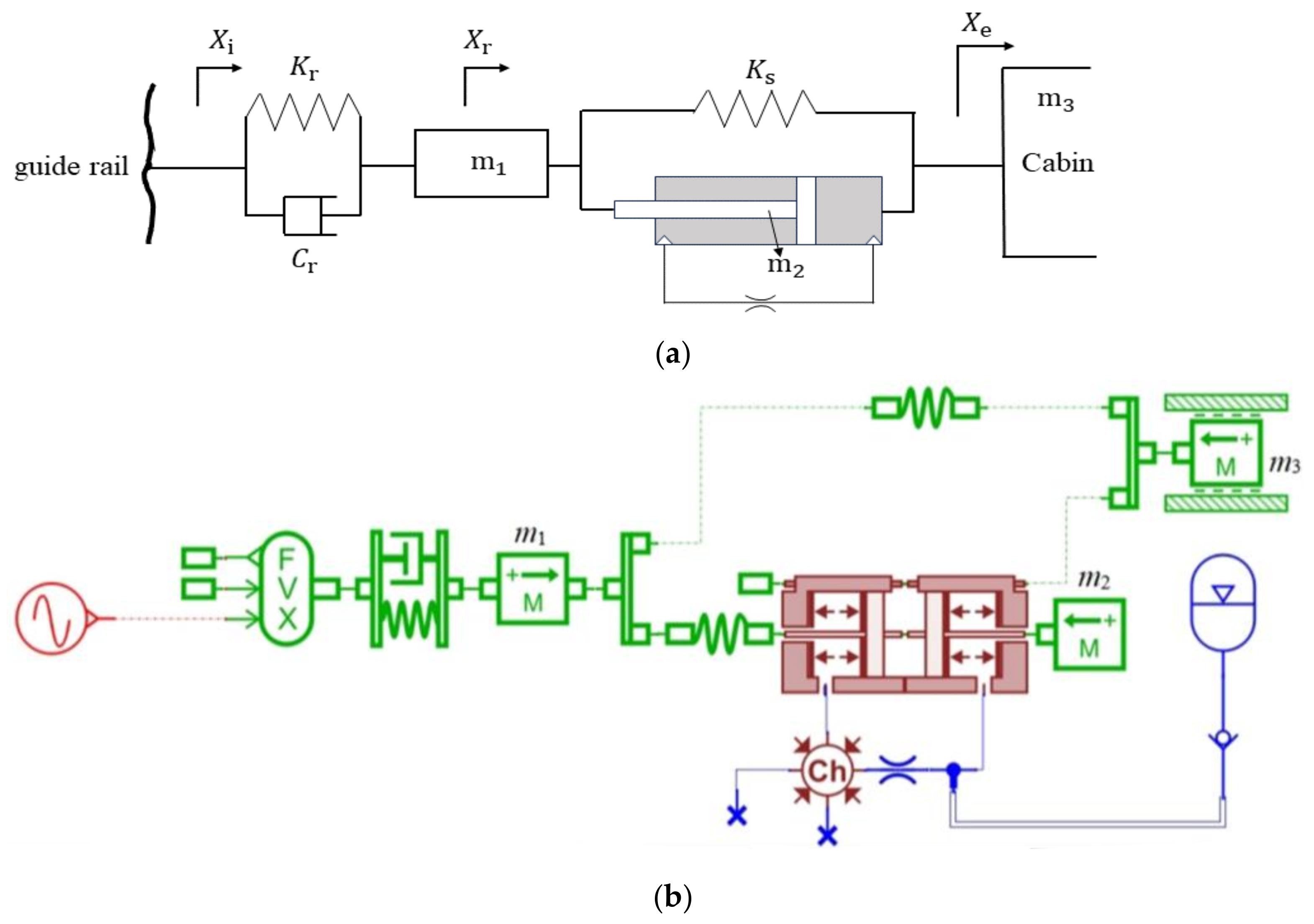
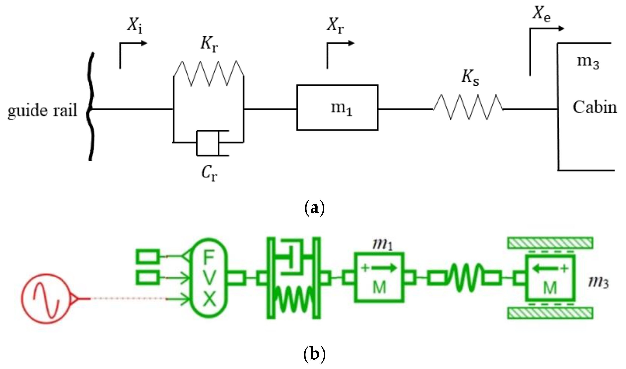
With the replacement of traditional rolling guide shoes by hydraulic-damping ones, the two-degree-of-freedom horizontal vibration model of these shoes with hydraulic damping is depicted in Figure 9a, and the corresponding AMESim2020-based model is illustrated in Figure 9b [22]. To ensure the comparability of the simulation results, a model of traditional rolling guide shoes without hydraulic damping was included. Except for the hydraulic actuator and the hydraulic damping, the working principle and simulation parameters of the mechanical structure were consistent between the two models. The two-degree-of-freedom model and the AMESim2020-based model of traditional rolling guide shoes were refined and developed, as shown in Figure 10.
The simulation parameters are partially based on the actual specifications of the elevator under investigation, while others are sourced from data provided by domestic researchers [20]. These values are detailed in Table 3, and the external excitation signals from the guide rail, as listed in Table 2, are used as the input source for simulating vibration signals. The vibration reduction performance of the guide shoes was evaluated under three typical cabin load conditions: no-load (2000 kg), half-load (2500 kg), and full-load (3000 kg).

4.2. Key Parameters of Hydraulic Damping

Hydraulic damping is employed to mitigate the effects of fluid vibrations and absorb energy, thereby effectively reducing the overall vibrations. The size of the hydraulic damping directly influences the performance of the new rolling guide shoes, necessitating accurate calculation to determine the appropriate damping size. Therefore, by referring to the calculation method used to determine the optimal damping ratio in vehicle suspension systems, an attempt was made to determine the appropriate hydraulic damping aperture size for the elevator guide shoes [23]. The equations representing the optimal damping ratio for vehicle suspension systems based on comfort are provided in Equations (1)–(3).
ξ 0 = 1 2 1 + r m r m r k
r m = m 2 m 1
r k = k r k s
The formula for calculating the optimal damping coefficient of the suspension system is represented by Equation (4) to Equation (5).
C S = 2 ξ 0 m 2 ω 0
ω 0 = k s m 2
When the optimal damping coefficient is reached, the running speed of hydraulic actuator piston should be:
v s = F C s
At this stage, the oil flow through the damping hole corresponds to the flow generated by the movement of the piston in the hydraulic actuator. The flow formula for hydraulic damping is as follows:
q 0 = C q A 0 2 Δ P ρ
A 0 = π 4 d 0 2
P represents the pressure difference on both sides of the hydraulic actuator piston, and it reflects as the damping force:
Δ P = F A
A = π 4 D 2 d 2
Among these, A represents the region where hydraulic oil acts within the hydraulic actuator. As the piston rod shifts laterally within the hydraulic actuator, the displaced oil is transferred back to the opposing chamber through the damping hole, resulting in:
q s = q 0
v s A = C q A 0 2 Δ P ρ
Based on the preceding equations, the calculations reveal that, under typical load conditions—specifically, no-load at 2000 kg, half-load at 2500 kg, and full-load at 3000 kg—the optimal theoretical diameters of the hydraulic damping hole are 5.62 mm, 5.31 mm, and 5.08 mm, respectively. These values will serve as parameters for the hydraulic damping hole diameter in the simulation.

4.3. Simulation Results

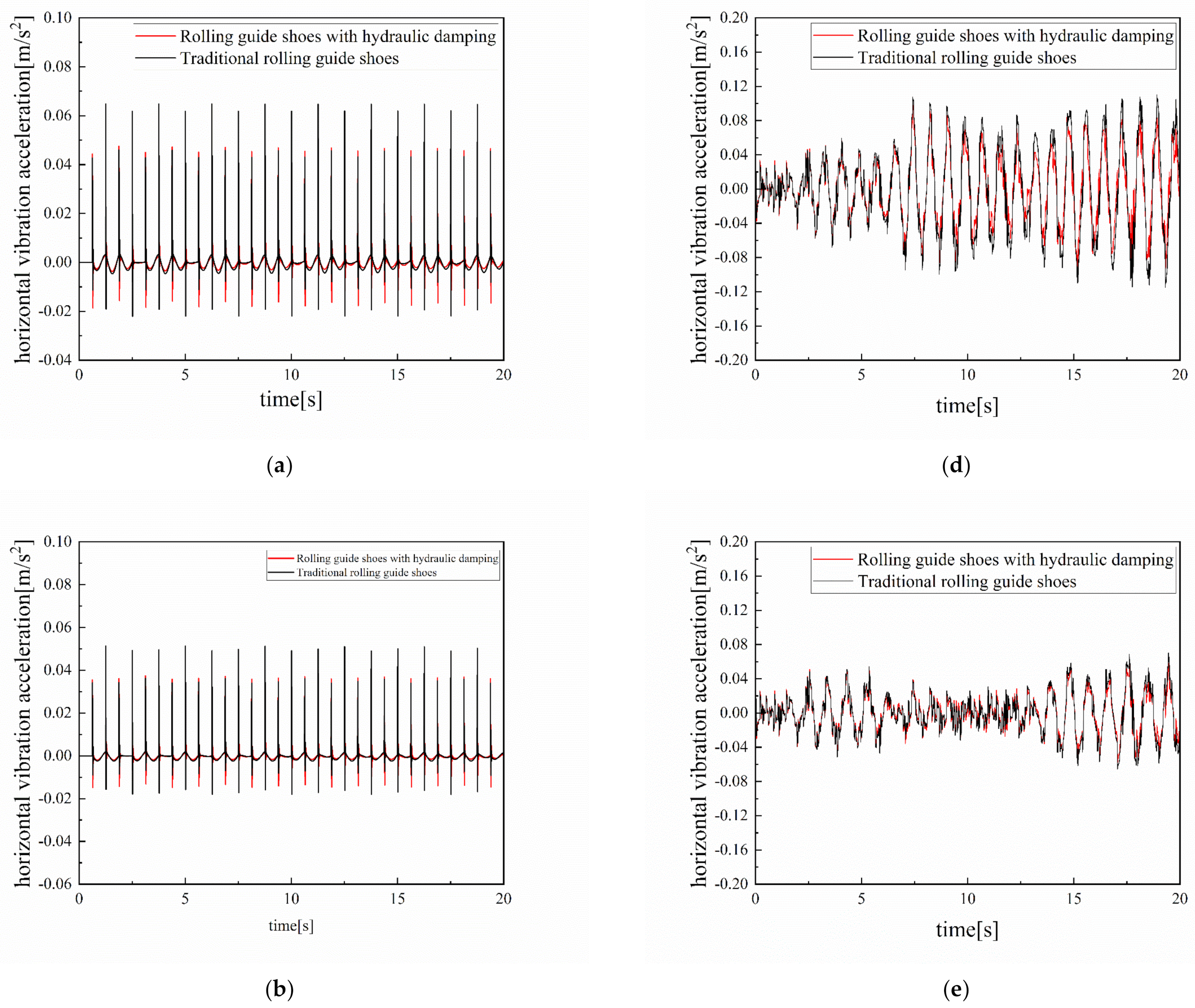
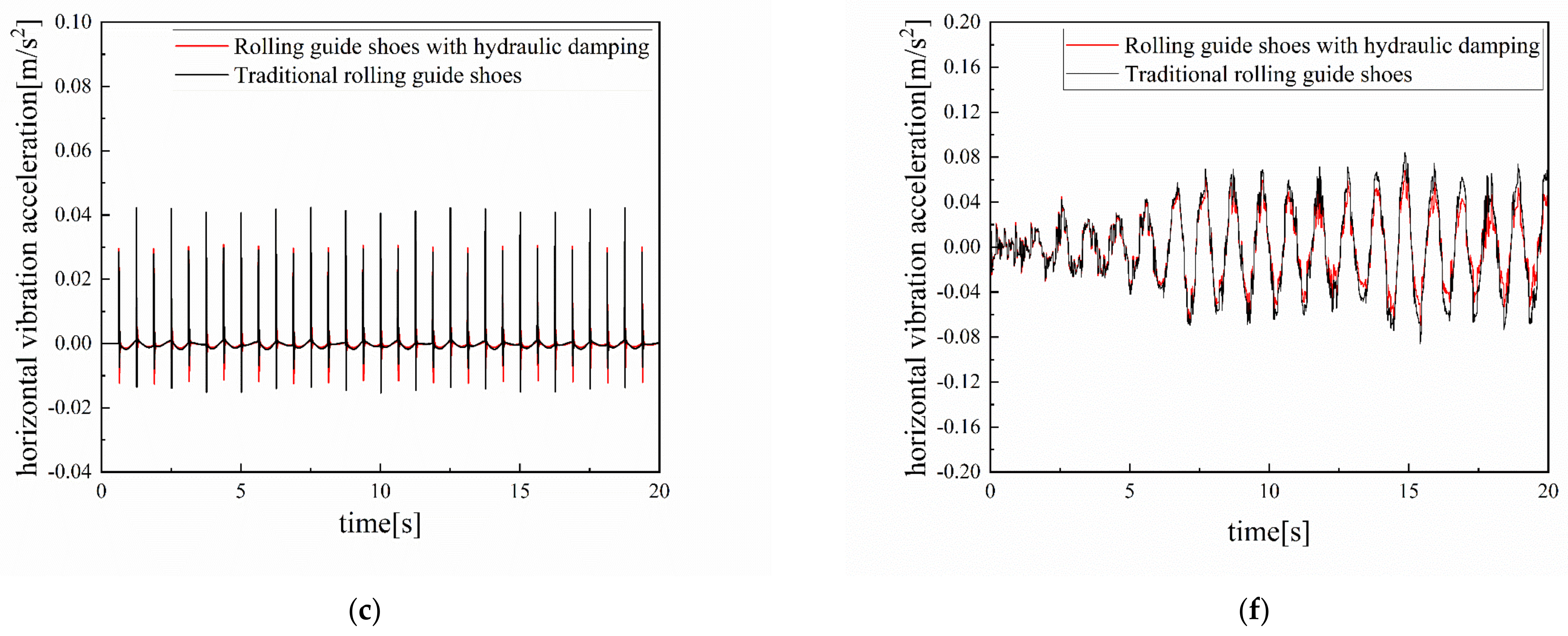
The figures below present comparison curves of horizontal vibration acceleration for an elevator cabin equipped with rolling guide shoes, featuring hydraulic damping versus traditional rolling guide shoes, under various external vibration excitations and cabin load conditions.
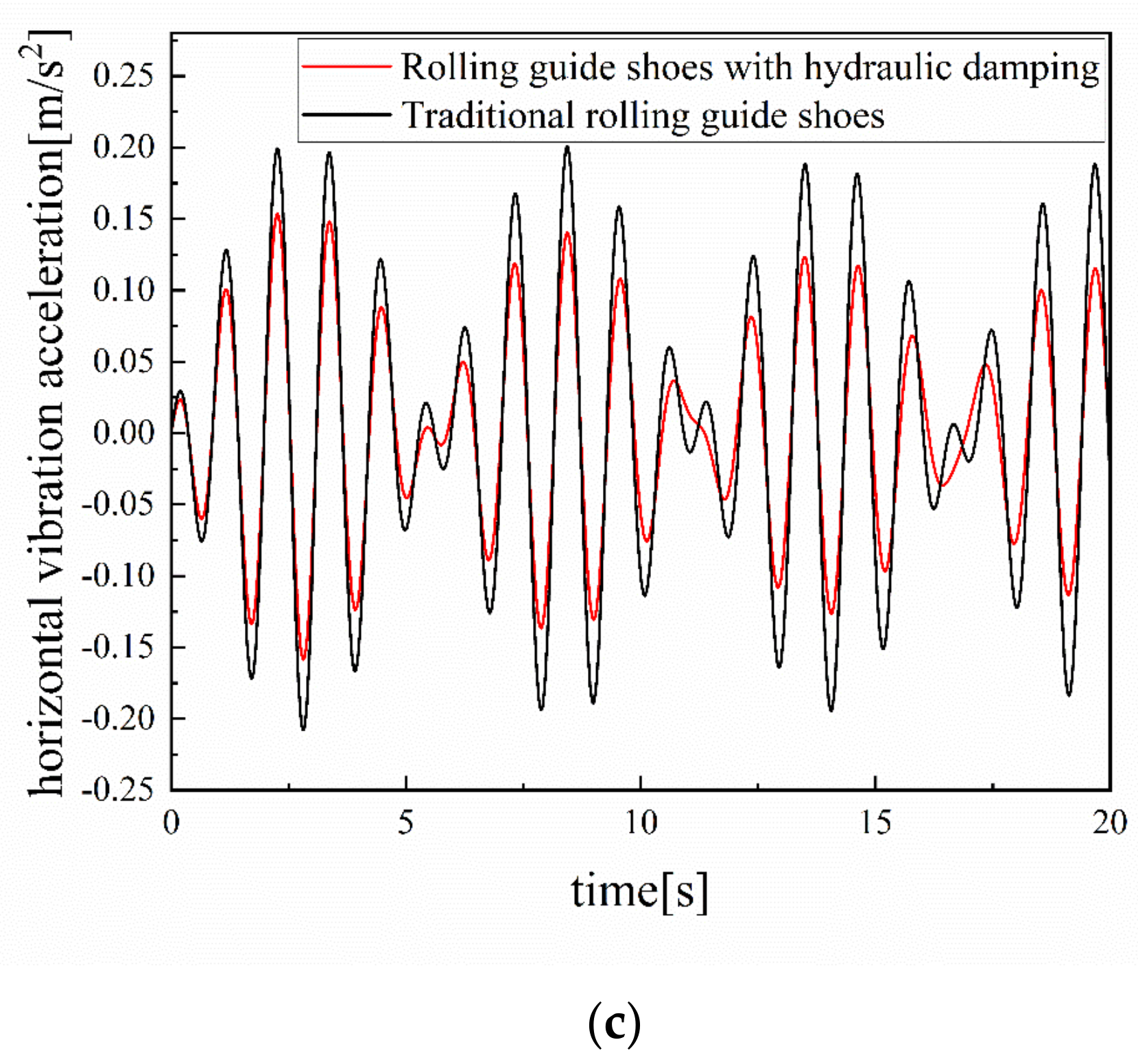
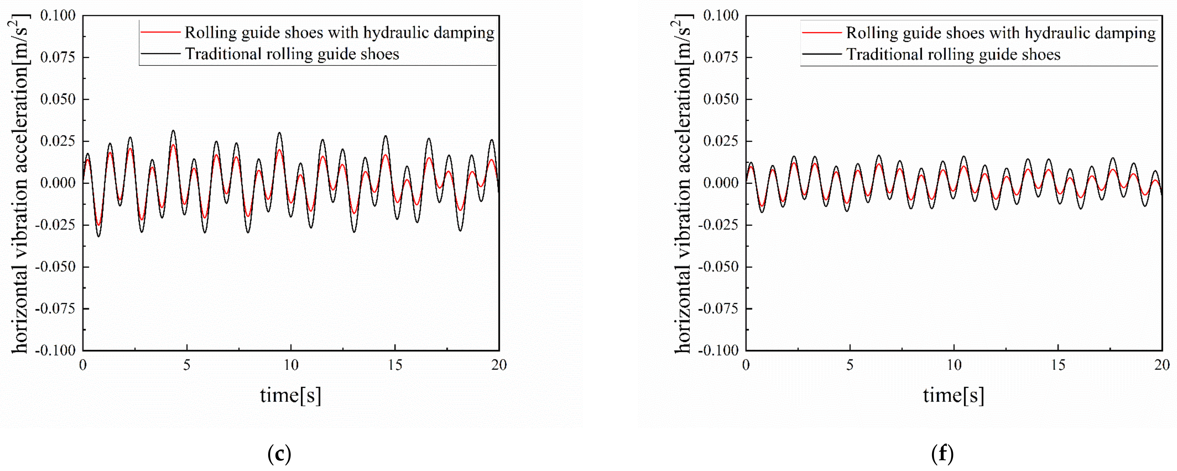
According to Figure 11 and Figure 12, the horizontal vibration acceleration data of the elevator cabin under sine wave excitation (with the amplitude of 2 mm but different frequencies) are shown in Table 4.
As shown in Table 4:
(1) Under the excitation of a 0.8 Hz sine wave and with traditional rolling guide shoes, the elevator reaches its maximum horizontal vibration acceleration. For no-load at 2000 kg, half-load at 2500 kg, and full-load at 3000 kg, the horizontal vibration acceleration values are 0.135 m/s2, 0.162 m/s2, and 0.208 m/s2, respectively. These data closely align with the specifications in GB/T 10058-2009 “Elevator Technical Conditions”, which stipulate that “the maximum peak-to-peak value of horizontal vibration during elevator car operation should not exceed 0.2 m/s2”. The results from the modeling and simulation analysis using AMESim2020 are in close agreement with the limit values specified in the standard. Furthermore, the simulation results are consistent with those obtained by technical personnel from the Sicher Elevator Company in November 2023 [24,25], thereby validating the effectiveness of the AMESim2020-based modeling and simulation.
(2) When comparing the vibration acceleration values of the elevator car under sine wave excitations at 0.8 Hz, 0.4 Hz, and 0.267 Hz, it is observed that, with traditional rolling guide shoes and excitation at 0.4 Hz, the horizontal vibration acceleration of the cabin at 2000 kg (no-load), 2500 kg (half-load), and 3000 kg (full-load) are 0.135 m/s2, 0.162 m/s2, and 0.208 m/s2, respectively. The corresponding values under 0.267 Hz sine wave excitation are 0.0197 m/s2, 0.0184 m/s2, and 0.0175 m/s2, respectively. Furthermore, these values are reduced when using rolling guide shoes with hydraulic damping, indicating that the horizontal vibration acceleration decreases significantly with a reduction in sine wave excitation frequency. This also suggests that the horizontal vibration caused by sine wave excitation, considering the four or six guide rails bent into cycles, is minimal and has a negligible impact on cabin comfort. Therefore, the subsequent analysis will focus on sine wave excitation at 0.8 Hz.
From Figure 11 and Figure 13, the maximum horizontal acceleration of rolling guide shoes with hydraulic damping and the maximum horizontal vibration acceleration of the traditional rolling guide shoes under different working conditions were taken and compared. The comparison dates obtained are shown in Table 5.
Based on the figures and tables above, it is observed that:
(1) Under identical excitation and load conditions, the horizontal vibration acceleration of elevators equipped with rolling guide shoes featuring hydraulic damping is lower than that of elevators using traditional rolling guide shoes. Specifically, the reduction in vibration acceleration under pulse excitation ranges from 26.2% to 27.5%, under white noise excitation from 14.3% to 17.1%, and under sine wave excitation from 22.2% to 24.1%. The use of passive-control rolling guide shoes with hydraulic damping offers more effective suppression of horizontal vibration in the elevator cabin as compared to traditional rolling guide shoes, thereby validating their effectiveness. Under pulse excitation, hydraulic damping passive-control rolling guide shoes demonstrate the most effective vibration suppression.
(2) Compared to pulse excitation and white noise excitation, sine wave excitation at 0.8 Hz results in the highest horizontal vibration acceleration of the elevator. This suggests that sine wave excitation, associated with the periodic bending of the guide rails, has the most significant impact on the horizontal vibration of the elevator car. Therefore, during the installation and maintenance of elevator guide rails, it is crucial to account for rail bending to minimize its impact on horizontal vibration acceleration. Additionally, for pulse excitation and white noise excitation, the horizontal vibration acceleration of elevators equipped with passive-control rolling guide shoes with hydraulic damping is ≤0.10 m/s2, which meets the criteria for first-class products.

4.4. Impact of Other Parameters on Vibration Reduction Performance

To further investigate the influence of various parameters on the vibration reduction performance of rolling guide shoes with hydraulic damping, a simulation was conducted under the following conditions: a full-load elevator cabin of 3000 kg and 0.8 Hz sine wave excitation, which maximizes the elevator’s horizontal vibration acceleration. The simulation involved varying the roller stiffness coefficient, the roller damping coefficient, and the hydraulic damping aperture individually while keeping all other parameters constant. The study focused on analyzing the changes in horizontal vibration acceleration resulting from modifications to these three parameters.
(1) 
Changing the roller stiffness coefficient
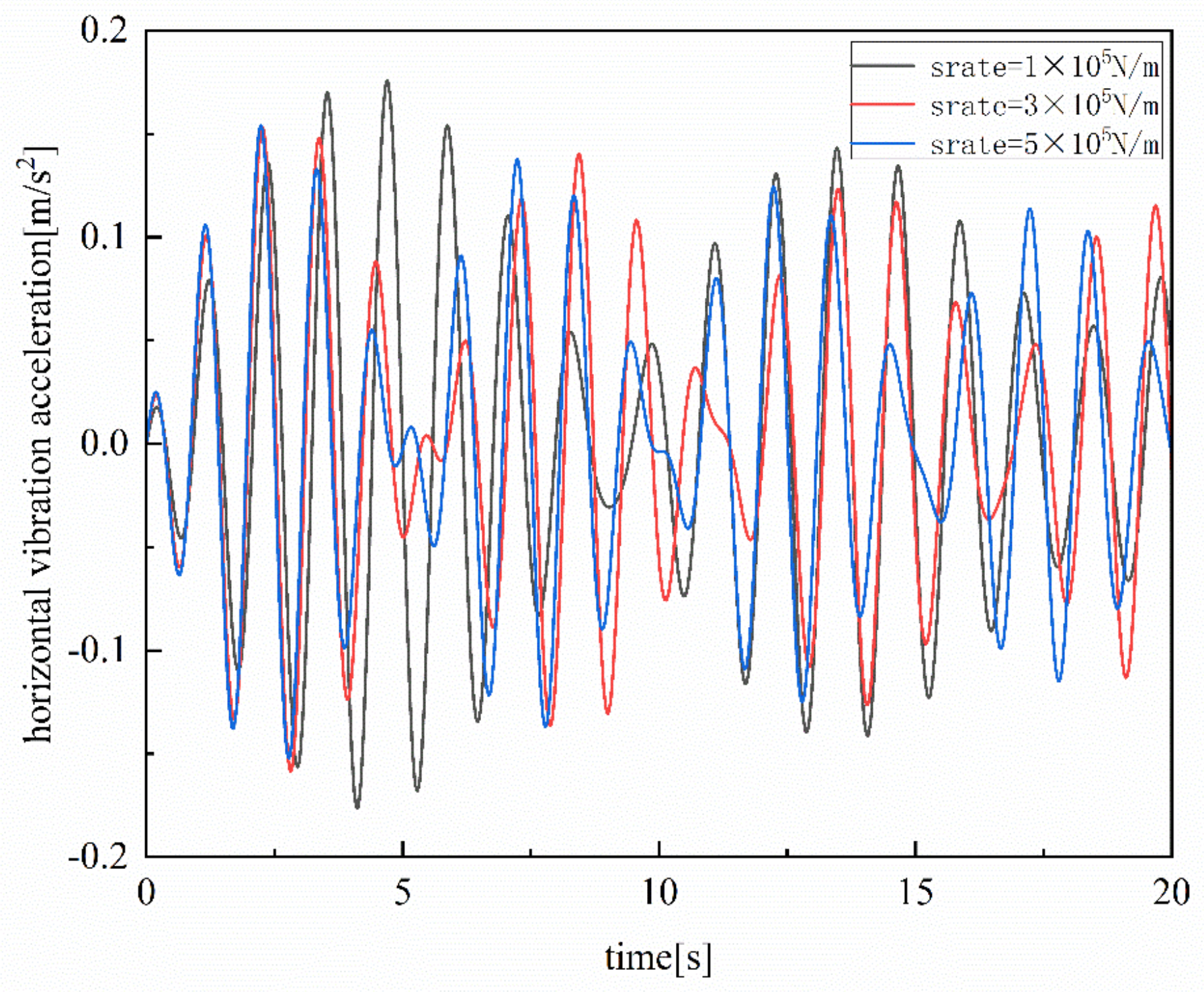
The outer ring of the roller is composed of damping rubber, and the stiffness coefficient, which is in contact with the guide rail, is dictated by the material’s inherent properties. The initial stiffness coefficient of the roller, as investigated in this study, is 3 × 10⁵ N/m. To examine the effect of this parameter on elevator vibration acceleration, we systematically adjusted the stiffness coefficients of the rollers in the simulation to 1 × 10⁵ N/m, 3 × 10⁵ N/m, and 5 × 10⁵ N/m. The simulation curve depicting the horizontal vibration acceleration of the elevator is presented in the following figure.
The Figure 14 illustrates that the amplitude of the horizontal vibration acceleration in the elevator cabin decreases with an increase in the roller stiffness coefficient. However, the change in amplitude is minimal. Moreover, when the roller stiffness coefficient is 3 × 10⁵ N/m, the peak horizontal vibration acceleration of the elevator is relatively stable. This suggests that the current rubber material is appropriate for roller selection, and there is no necessity to incur additional costs by opting for materials with either higher or lower stiffness coefficients.
(2) 
Changing the roller damping coefficient
Similarly, the damping coefficient of the roller is dictated by the material’s inherent properties. To investigate the effect of varying the damping coefficient on vibration reduction performance, the damping coefficients of the roller were set at 120 N/(m·s), 920 N/(m·s), and 1720 N/(m·s). The simulation curves depicting the elevator’s horizontal vibration acceleration are presented in the following figure.
Figure 15 indicates that variations in the damping coefficient of the roller have negligible effects on the vibration acceleration. Consequently, it can be concluded that modifying the roller material and increasing its damping coefficient have minimal impact on improving the vibration reduction performance of the rolling guide shoes.
(3) 
Change in the hydraulic damping hole’s diameter
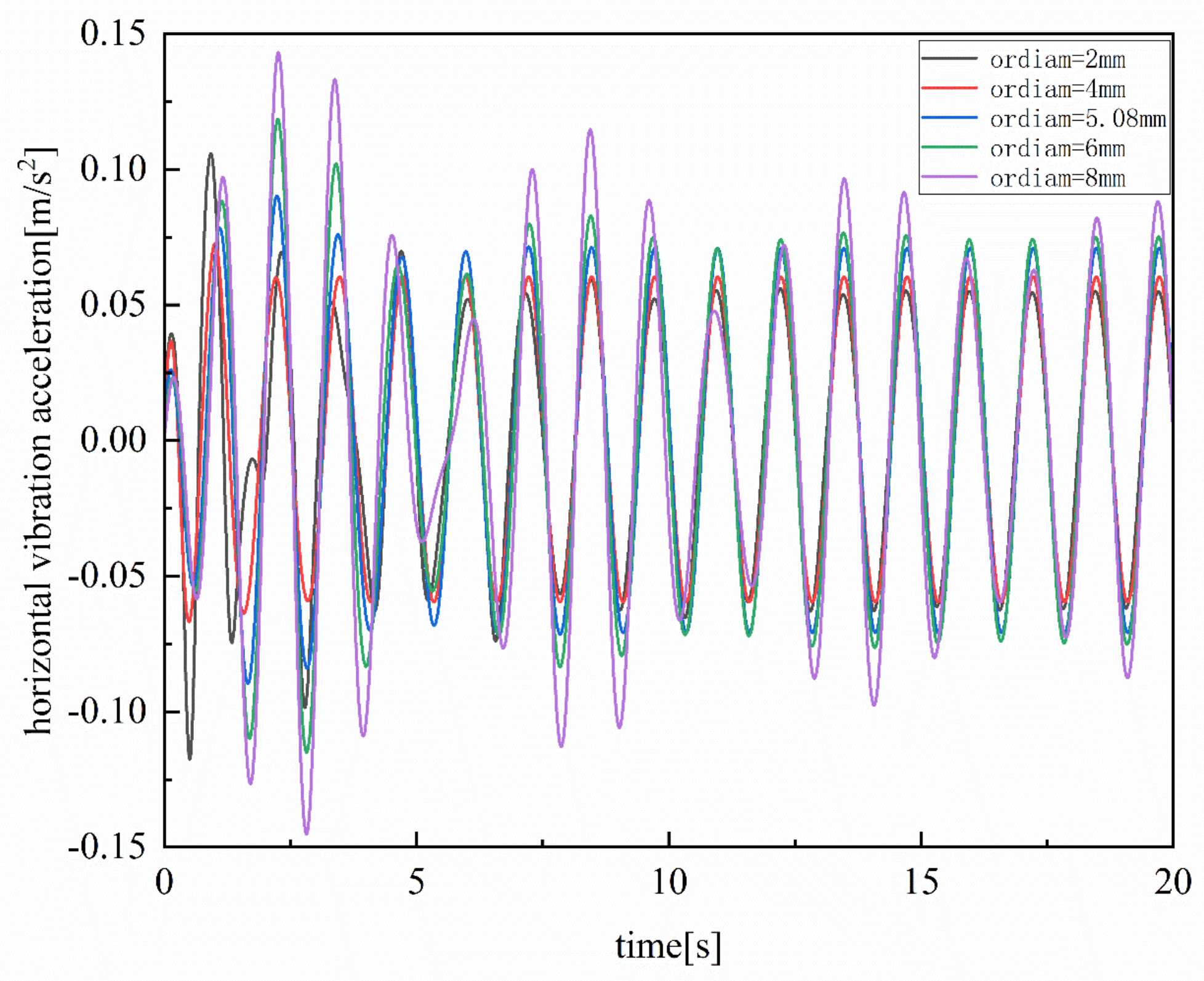
The diameter of the damping hole is a critical parameter for hydraulic damping rolling guide shoes and distinguishes them from traditional rolling guide shoes. In Section 4.2, we theoretically determined the aperture values of the damping hole under various load conditions. The calculated aperture value was 5.08 mm under a full load of 3000 kg. To further investigate the effect of this parameter on elevator vibration acceleration, we set its values to 2 mm, 4 mm, 5.08 mm, 6 mm, and 8 mm in the simulation. The simulation curves illustrating the corresponding horizontal vibration acceleration of the elevator are presented in the following figure.
Figure 16 shows that the horizontal vibration acceleration of the elevator increases with the damping aperture. If the damping hole is too large, the movement of the rocker arm drives the hydraulic actuator piston, causing hydraulic oil to flow through the damping hole. This results in a minimal damping effect and ineffective vibration suppression. Conversely, when the damping aperture is relatively small, such as 2.0 mm, the initial stage of the horizontal vibration acceleration will exhibit a significant peak. The hydraulic oil experiences a sudden increase in internal pressure when transitioning from stationary to moving. This is due to the small damping aperture, which prevents the hydraulic oil from dissipating pressure promptly, leading to a sudden rise in vibration acceleration.
Additionally, the figure shows that within the damping aperture range of 4 mm to 6 mm, the horizontal vibration acceleration remains relatively uniform. This observation aligns with the theoretical calculation range of 5.08 mm to 5.62 mm, demonstrating the accuracy of the theoretical predictions.

4.5. Comparison of Performance

Based on the principles of composition and the simulation effects of passive-control rolling guide shoes with hydraulic damping, a comparison was conducted among passive-control rolling guide shoes with hydraulic damping, traditional passive-control rolling guide shoes, and active-control rolling guide shoes in terms of cost, maintenance, and effectiveness, as illustrated in Table 6.

5. Conclusions

To elevate the stability and riding comfort of elevators, this study introduces a passive-control approach leveraging hydraulic damping as a means to mitigate horizontal vibrations. The feasibility of this theoretical framework and its corresponding implementation strategy are rigorously validated through a combined mechanical and hydraulic simulation. The key findings of this research endeavor are condensed and presented in an academic manner as follows:
(1) In the realm of high-speed and ultra-high-speed elevators, the reliance on active-control guide shoes is not an absolute necessity. Rather, the adoption of passively controlled rolling guide shoes, optimized with judicious parameter selection and structural refinement, emerges as a viable and cost-effective alternative. Notably, the integration of hydraulic damping within rolling guide shoes merits further exploration due to its inherently advantageous damping characteristics.
(2) The empirical outcomes indicate that the proposed passive-control rolling guide shoes with hydraulic damping, upon fine-tuning their hydraulic damping parameters, demonstrate remarkable vibration suppression capabilities as compared to conventional passive-control rolling guide shoes when subjected to uneven guide rail excitations. Specifically, under pulse excitation, the vibration reduction ranges from 26.2% to 27.5%; under white noise excitation, from 14.3% to 17.1%; and under sine wave excitation, from 21.2% to 24.1%. Notably, it surpasses the ‘Excellent’ performance benchmark (≤0.07 m/s2) under low-frequency sine wave excitation conditions, underscoring the enhanced vibration attenuation properties of passive-control rolling guide shoes with hydraulic damping over their traditional counterparts. Additionally, the significantly simplified design of these passive-control guide shoes, in comparison to active-control alternatives, underscores their cost-effectiveness, positioning them as a promising solution for elevator guide shoes and justifying further investigative efforts.
(3) Furthermore, this investigation reveals that sine wave excitation emanating from guide rail bending exerts the most pronounced influence on the horizontal vibrations of high-speed elevator cars. Consequently, during the installation and maintenance of elevator guide rails, it is imperative to meticulously address guide rail bending to mitigate its detrimental effects on the acceleration of horizontal vibrations within elevators. This insight underscores the criticality of addressing guide rail bending as a fundamental aspect of ensuring elevator ride quality and stability.

Author Contributions

D.H. designed the program and created the draft. Q.W. provided research recommendations. J.Z. revised the manuscript. All authors have read and agreed to the published version of the manuscript.

Funding

This research was funded by Major Science and Technology Research Projects of Ningbo (2024Z165).

Data Availability Statement

The data presented in this study are available on request from the corresponding author.

Acknowledgments

The authors would like to thank Sicher Elevator Co., Ltd., for providing partial data support.

Conflicts of Interest

The authors declare no conflicts of interest.

References

  1. Liu, D.B. The Skyscraper Impulse. Build. Mater. Constr. Decor. 2014, 16–21. [Google Scholar] [CrossRef]
  2. Chen, J.W.; Zhang, X.Z.; Li, X. Principle and Control of Elevator Structure; Chemical Industry Press: Beijing, China, 2017. [Google Scholar]
  3. Chen, H.Y. Discussion about Elevator Vibration Reasons and Damping Methods. Mech. Eng. 2014, 1, 250–252. [Google Scholar]
  4. Yin, J.C. Research on the Vibration in Traction System Medium-high Speed Elevator. Master’s Thesis, SuZhou University, Suzhou, China, 2011. [Google Scholar]
  5. Ye, J. Analysis of the Causes of Elevator Operation Vibration and Discussion on Countermeasure. China Plant Eng. 2019, 16, 81–83. [Google Scholar]
  6. Zhang, Y. Research on the ride comfort of elevator monitoring using smartphone. In Proceedings of the SPIE Smart Structures and Materials + Nondestructive Evaluation and Health Monitoring, Portland, OR, USA, 25–29 March 2017. [Google Scholar]
  7. Hamdy, A. Active damping of vibrations in elevator cars. Struct. Control. Health Monit. 1999, 6, 53–100. [Google Scholar] [CrossRef]
  8. Schmulling, B.; Effing, O.; Hameyer, K. State control of an electromagnetic guiding system for ropeless elevators. In Proceedings of the in 2007 European Conference on Power Electronics and Applications, Aalborg, Denmark, 2–5 September 2007; pp. 1–10. [Google Scholar]
  9. Appunn, R.; Schmülling, B.; Hameyer, K. Electromagnetic Guiding of Vertical Transportation Vehicles: Experimental Evaluation. IEEE Trans. Ind. Electron. 2009, 57, 335–343. [Google Scholar] [CrossRef]
  10. Schmulling, B.; Hameyer, K. Decoupling and adjustment of forces in an electromagnetic guiding system with six degrees of freedom. COMPEL Electr. Electron. Eng. 2011, 30, 1011–1018. [Google Scholar] [CrossRef]
  11. Noguchi, N.; Arakawa, A.; Miyata, K.; Yoshimura, T.; Shin, S. Study on Active Vibration Control for High-Speed Elevators. J. Syst. Des. Dyn. 2011, 5, 164–179. [Google Scholar] [CrossRef]
  12. Noguchi, N.; Arakawa, A.; Miyoshi, K.; Kawamura, Y.; Yoshimura, T. Active vibration control technology for elevator cars considering controllability. Transact. Japan Soc. Mech. Eng. Series C 2013, 79, 3192–3205. [Google Scholar] [CrossRef]
  13. Hu, D.M.; Gao, X.C.; Wang, Q.B. Passive control Elevator Rolling Guide Shoes with Hydraulic Damping. Chinese Patent ZL 2022 2 2696572.0, 13 October 2022. [Google Scholar]
  14. Song, D.; Bai, Y.; Zhang, X.; Cui, Y.; Liu, K.; Lu, X. Analysis and optimization of horizontal vibration isolation performance of elevator rolling guide shoes. J. Mach. Des. 2021, 38, 34–41. [Google Scholar]
  15. Mei, D.Q.; Du, X.Q.; Chen, Z.C. Vibration analysis of high-speed traction elevator based on guide roller-rail contact model. J. Mech. Eng. 2009, 45, 264–270. [Google Scholar] [CrossRef]
  16. Wu, H. Study on Dynamic Characteristics of High-Speed Traction Elevator. Master’s Thesis, Nanjing University of Aeronautics and Astronautics, Nanjing, China, 2013. [Google Scholar]
  17. Feng, Y.H. Active Control of Horizontal Vibrations for High—Speed Elevator. Ph.D. Thesis, Shanghai Jiao Tong University, Shanghai, China, 2008. [Google Scholar]
  18. GB/T10058-2009; Specification for Electric Lifts. National Standard of the People’s Republic of China: Beijing, China, 2009.
  19. GB/T 24474.1-2020; Measurement of Ride Quality Part 1: Lifts (Elevators). National Standard of the People’s Republic of China: Beijing, China, 2020.
  20. Zhang, P. Research on Nonlinear Control of Lateral Vibration in High Speed Elevator Car System. Master’s Thesis, Shandong Jianzhu University, Jinan, China, 2022. [Google Scholar]
  21. GB/T22562-2008; Guide Rails for Lifts—T-Type. National Standard of the People’s Republic of China: Beijing, China, 2008.
  22. Fu, Y.; Qi, X. AMESim System Modeling and Simulation—From Beginner to Proficient; Beihang University Press: Beijing, China, 2006. [Google Scholar]
  23. Zhou, C. Design and Theory of Automotive Hydraulic Cylinder Shock Absorber; Peking University Press: Beijing, China, 2012. [Google Scholar]
  24. High-Speed Elevator Operation Test Report; Sicher Elevator Co., Ltd.: Huzhou, China, 2023.
  25. Gao, X.C. Research on Vibration Reduction Characteristics of High-Speed Elevator Guide Shoes Based on Passive Hydraulic Damping Control. Master’s Thesis, Anhui University of Science and Technology, Huainan, China, 2022. [Google Scholar]
Figure 1. Diagram of the types of elevator rolling guide shoes.
Actuators 13 00356 g001
Figure 2. The diagram of the elevator car and guidance system.
Actuators 13 00356 g002
Figure 3. Diagram of rolling guide shoes.
Actuators 13 00356 g003
Figure 4. Schematic diagram of guide rail joints and pulse signals.
Actuators 13 00356 g004
Figure 5. Schematic diagram of guide rail bending and sine wave signals.
Actuators 13 00356 g005
Figure 6. Schematic diagram of guide rail surface wear and white noise signals.
Actuators 13 00356 g006
Figure 7. Schematic diagram of a rolling guide shoe with hydraulic damping.
Actuators 13 00356 g007
Figure 8. The two-degree-of-freedom models: (a) elevator car and guidance system and (b) single traditional rolling guide shoe.
Actuators 13 00356 g008
Figure 9. Models of the rolling guide shoes with hydraulic damping: (a) dynamic model and (b) simulation model.
Actuators 13 00356 g009
Figure 10. Models of the traditional rolling guide shoes: (a) dynamic model and (b) simulation model.
Actuators 13 00356 g010
Figure 11. Comparison of vibration performance under different operating conditions II: (a) 2000 kg and sine wave excitation (0.8 Hz), (b) 2500 kg and sine wave excitation (0.8 Hz), and (c) 3000 kg and sine wave excitation(0.8 Hz).
Actuators 13 00356 g011aActuators 13 00356 g011b
Figure 12. Comparison of vibration performance under different operating conditions III: (a) 2000 kg and sine wave excitation (0.4 Hz), (b) 2500 kg and sine wave excitation (0.4 Hz), (c) 3000 kg and sine wave excitation (0.4 Hz), (d) 2000 kg and sine wave excitation (0.267 Hz), (e) 2500 kg and sine wave excitation (0.267 Hz), and (f) 3000 kg and sine wave excitation (0.267 Hz).
Actuators 13 00356 g012aActuators 13 00356 g012b
Figure 13. Comparison of vibration performance under different operating conditions I: (a) 2000 kg and pulse excitation (1.6 Hz), (b) 2500 kg and pulse excitation (1.6 Hz), (c) 3000 kg and pulse excitation (1.6 Hz), (d) 2000 kg and white noise excitation, (e) 2500 kg and white noise excitation, and (f) 3000 kg and white noise excitation.
Actuators 13 00356 g013aActuators 13 00356 g013b
Figure 14. Influence of the roller stiffness coefficient on the vibration reduction performance.
Actuators 13 00356 g014
Figure 15. Influence of the roller damping coefficient on the vibration reduction performance.
Actuators 13 00356 g015
Figure 16. Influence of the hydraulic damping hole’s diameter on the vibration reduction performance.
Actuators 13 00356 g016
Table 1. Horizontal acceleration requirements for elevators of different grades.
GradeQualifiedFirst GradeExcellent
Acceleration (m/s2)≤0.20≤0.10≤0.07
Table 2. External excitation signals used for this study.
Signals TypePulseSine Wave 1
(2 Guide Rails/Cycle)
Sine Wave 2
(4 Guide Rails/Cycle)
Sine Wave 3
(6 Guide Rails/Cycle)
White Noise
Characteristics
Frequency (Hz)1.60.80.40.267random
Amplitudes (mm)22220.75
Table 3. Computational parameters.
Nomenclature
A0The flow area of the hydraulic damping hole (mm2)m3Mass of cabin (value no-load 2000 kg, half load 2500 kg, and full load 3000 kg respectively)
AAction area of hydraulic oil in the hydraulic actuator (mm2) PPressure difference between both sides of the hydraulic actuator piston (MPa)
CqHydraulic flow coefficient (value 0.62)q0Flow rate of damping hole (L/min)
CrDamping coefficient of the roller (value 920 N/(m/s))qsFlow rate of hydraulic actuator (L/min)
CsOptimal damping coefficientrkStiffness ratio of roller to the spring on guide shoes
dDiameter of piston rod (value 22 mm)rmMass ratio of cabin to roller
DDiameter of piston (value 40 mm)vsRunning speed of hydraulic actuator piston (m/s)
d0Diameter of hydraulic damping hole (mm)ω0Natural frequency of the cabin under the action of spring on rolling guide shoes (rad/s)
FDamping force (N)ρDensity of hydraulic oil (value 850 kg/m3)
krStiffness coefficient of the roller (value 3 × 10⁵ N/m)ξ0Optimal damping ratio
ksStiffness coefficient of the spring on rolling guide shoes (value 7 × 10⁴ N/m)XiInput vibration displacement caused by uneven excitation of guide rail (mm)
m1Mass of guide roller (value 5 kg)XrDisplacement of the rocker arm at the center of the roller (mm)
m2Mass of piston in hydraulic cylinder (value 1 kg)XeDisplacement of guide shoe base and elevator cabin (mm)
Table 4. Peak-to-peak values of the horizontal acceleration of the elevator cabin under running conditions of sine wave excitation with different frequencies.
Running
Conditions
Sine Wave Excitation
(0.8 Hz)
Sine Wave Excitation (0.4 Hz)Sine Wave Excitation
(0.267 Hz)
Horizontal
Acceleration
2000 kg2500 kg3000 kg2000 kg2500 kg3000 kg2000 kg2500 kg3000 kg
Rolling guide shoes with hydraulic damping (m/s2)0.1050.1250.1580.02600.02620.02510.01540.01440.0137
Traditional rolling guide shoes (m/s2)0.1350.1620.2080.03470.03340.03190.01970.01840.0175
Reduction amplitude22.2%22.8%24.1%25.1%21.6%21.3%21.2%21.7%21.7%
Table 5. Peak-to-peak value of the horizontal acceleration of the elevator cabin under different running conditions.
Running
Conditions
Pulse ExcitationSine Wave Excitation
(0.8 Hz)
White Noise Excitation
Horizontal
Acceleration
2000 kg2500 kg3000 kg2000 kg2500 kg3000 kg2000 kg2500 kg3000 kg
Rolling guide shoes with hydraulic damping (m/s2)0.0480.0370.0310.1050.1250.1580.0980.0600.068
Traditional rolling guide shoes (m/s2)0.0650.0510.0420.1350.1620.2080.1150.0700.082
Reduction amplitude26.2%27.5%26.2%22.2%22.8%24.1%14.7%14.3%17.1%
Table 6. Comparison of passive-control rolling guide shoes with hydraulic damping, traditional passive-control rolling guide shoes, and active-control rolling guide shoes.
CostMaintenanceEffectiveness
Traditional passive-control rolling guide shoeslow easyModerate
Passive-control rolling guide shoes with hydraulic dampingrelatively lowrelatively easyNotable
Active-control rolling guide shoeshighdifficultSignificant
Disclaimer/Publisher’s Note: The statements, opinions and data contained in all publications are solely those of the individual author(s) and contributor(s) and not of MDPI and/or the editor(s). MDPI and/or the editor(s) disclaim responsibility for any injury to people or property resulting from any ideas, methods, instructions or products referred to in the content.