Abstract
In several applications, the accuracy and robust performance of the control method for the speed of permanent magnet synchronous motors (PMSMs) is critical. Model uncertainties, caused by inaccurate model identification, decrease the accuracy of PMSM control. To solve this problem, this paper presents a super robust control structure for the speed control of PMSMs. In the proposed method, the model uncertainties with Lipschitz condition together with disturbances are considered during the PMSM modeling, and their effects are handled using a robust state feedback control. To be more specific, the Lyapunov stability proof is performed in such a way that the model uncertainty effects are eliminated. Before that, the Lyapunov stability criteria have been selected in such a way that the Hꝏ conditions are considered and guaranteed. This issue helps to eliminate the effects of the disturbances. In addition, this paper considers another option to make the whole control structure robust against sudden load changes. To solve this problem, a fuzzy adaptive sliding mode observer (FASMO) is presented to determine the load torque and use it in the control signal generation. In this observer, the switched gain of the sliding mode observer (SMO) is adapted using a fuzzy system to eliminate the chattering phenomena and increase the estimation accuracy. In fact, the proposed method is called super robust because it resists model uncertainties, disturbances, and sudden load changes during three stages by robust state feedback control, Hꝏ criterion, and load estimator, respectively. The performance of the proposed approach is validated through a set of laboratory tests, and its superiority is shown compared to other methods.
1. Introduction
Today, electric drives play an important role in industry. Electric motors and electronic power converters and control systems are the components of electric drives. Actuators are generally used for motion control, speed control, or position control purposes. Drives are used in many industries, such as aerospace, vehicles, and automation. Electric motors are the beating heart of electric drives and are of special importance. In recent years, permanent magnet synchronous motors (PMSMs) have attracted the attention of many researchers due to some of their features and characteristics.
Advanced control methods are commonly employed for high-performance tasks in areas such as manufacturing, mobile machinery, and industrial robotics. Mechatronic systems often face control challenges that affect precision. These challenges include dynamic nonlinearities, uncertainties in parameters, unknown loads, and disturbances [1,2]. To overcome these problems, this paper tries to introduce some novelties and precise control methods, especially for PMSM drives. Also, their efficiency is higher than similar induction motors due to the absence of electrical losses in the rotor. Also, compared to direct current motors, they have lower maintenance and repair costs due to the absence of a brush. With recent advances in semiconductors, materials, nonlinear control theories, and power electronics, the application of this class of motors in industry is increasing over time. PMSMs are mostly used in the low-to-medium power range [3]. These motors play an important role in motion applications, including robotics and precision instruments. In the control of PMSMs, it is necessary to consider the nonlinear model and coupling between the components. The control system should provide fast, accurate, and robust responses to uncertainties and external disturbances in the system. Due to the nonlinearity of the synchronous motor system, linear controllers will not perform well for the system in a wide working range [4]. As a result, for the efficiency of the electric drive in a wide working range, we will have to use nonlinear controls. The control of PMSMs is divided into two general strategies: scalar control and vector control. Scalar control is known as a simple and cheap method, but this control method does not have much effect on the transient state of the system. This issue has caused this method not to be used in precise and sensitive applications. Vector control is separated into two methods: direct torque control and field vector control. The field vector control strategy has advantages such as fast response, soft start-up, and appropriate initial acceleration [5]. Therefore, field vector control is sensitive to changes in motor parameters and external disturbances [6]. Therefore, external disturbances and uncertainties will have different effects on motor performance. Applying robust control in the field vector control strategy can compensate for the effect of uncertainties and disturbances and improve system performance. Direct adjustment of flux and torque is undertaken in the direct torque control (DTC) method. This method has a faster response compared to the field vector control. The DTC strategy is less dependent on motor parameters. Also, removing the transformations of the stationary coordinate system of the stator to the rotating coordinate system of the rotor and vice versa is one of the other advantages of this strategy [7]. Due to poor performance at low speeds, the mentioned strategy is not used in precise and sensitive applications [8].
Backstep control is used as one of the resistant control methods in controlling synchronous motors [9]. The backward control law consists of nonlinear and complex functions that are not easily obtained, and this is one of the problems of this control method [10]. Among other resistant methods that have been used in the control of synchronous motors, we can mention sliding mode control (SMC) [11,12,13]. In [11], feedback linearization is used for simplicity in controller design. However, the main problem in this article is the presence of acceleration as a variable in the control law. The acceleration variable is not easily obtained. The main problem in sliding mode control is the chattering phenomenon. These fluctuations are called vibrations. This phenomenon can stimulate some system dynamics and disrupt the system’s performance. Vibration causes mechanical systems to wear out and gradually lose parts. Two factors cause the phenomenon of vibration:
- (1)
- Presence of high frequencies in the control signal;
- (2)
- High gain in the control loop.
As a result, to reduce vibration, the above two factors should be considered and resolved. One of the methods to reduce vibration is to remove the sign function in the controller’s output. In [12], the saturation replaces the sign function in the controller’s output, and this has reduced the vibration. In [13], using adaptive control theory, the switching gain is approximated online. This has caused the vibration and control effort to be reduced compared to the conventional SMC method. Although the phenomenon of vibration is still seen in the controller’s output signal, one of the ways to reduce the phenomenon of vibration is the use of intelligent controls in SMC. Fuzzy systems have the most important role in these studies. Fuzzy control is known as an intelligent method in controlling complex systems. This control method does not need the model. Fuzzy control for PMSMs has also been used [14,15]. Fuzzy rules in fuzzy control are determined by an expert, although in some cases fuzzy rules and variables are obtained by trial and error. Of course, research has been conducted to improve this problem. For example, in [14], different parts of the controller are parameterized, and genetic algorithm (GA) is utilized to make the controller optimized. In this method, there is no need for detailed information about the system’s performance and the knowledge of an expert. The controller itself achieves optimal conditions. The results of [14] show that the sensitivity to disturbances and fluctuations has increased compared to the conventional fuzzy control. Another method is provided to adjust the variables of the fuzzy controller. In this method, neural networks are used for fuzzy controller settings. This category of fuzzy controllers is called neural fuzzy control [16]. Fuzzy neural control [17,18] is designed to control the speed of the synchronous motor in such a way that the neural network adjusts the membership functions in the fuzzy controller. This unique feature has led many researchers to improve the performance of controllers by combining this logic with other control methods. Fuzzy control is resistant to uncertainties and external disturbances, but this control method is not as powerful as SMC in overcoming uncertainties and disturbances. Fuzzy systems can improve the conditions and performance of SMCs. Fuzzy systems can reduce vibration or estimate the information required in the sliding mode control law. For example, in [19], a hybrid controller is designed, which is an SMC in the range of large errors and becomes a neural fuzzy controller in the range of small errors. This solution greatly reduces vibration and is more resistant to fuzzy control.
Another commonly used control method for PMSMs is model predictive control (MPC) [20]. In this control method, a cost function for optimization is defined so that an optimization algorithm is executed during the production of the control law to produce the best signal for the control of the system. It is possible to combine MPC with other numerical methods (for example LMI) [21], and depending on whether the predictive range of this control technique is restricted or boundless, it is capable of generating an ideal reaction at every time interval to manage the system. Some studies use adaptive types of MPC or robust types [22] of predictive control to increase the accuracy and robustness of the control system. In some research, the MPC is mixed with other methods, such as SMC [23,24], to provide an accurate and robust performance against model uncertainties.
Although the sensitivity of the system to uncertainties and disturbances has increased compared to conventional sliding mode control [25,26], in [26], an adaptive fuzzy mechanism is designed for optimal estimation of switching gain. This reduces vibration and control effort compared to conventional sliding mode control and sliding mode control [25]. In most of the research conducted for the control of synchronous motors, the electrical dynamics of the motor have not been considered in the analysis and design of the controller. In precise and sensitive applications, it is essential to focus on this aspect of the motor.
In several applications, the robustness and accuracy of the control of PMSMs are critical, especially when the model uncertainties cause inaccuracy. This paper presents a super robust solution for this issue and introduces a robust control for PMSMs based on load torque observation. In this regard, the model uncertainties and disturbances have been considered in the nonlinear dynamics of PMSMs. In the proposed method, the uncertainties adhere to the Lipschitz condition, and by employing robust state feedback control, the impact of these uncertainties is mitigated. In other words, the Lyapunov stability proof is performed considering the Lipschitz condition to be sure about the elimination of the uncertainty effects. In addition, considering and guaranteeing the Hꝏ conditions, the Lyapunov stability criteria are corrected and proven to eliminate the effect of the disturbances. Moreover, this paper considers another additional option to make the whole control structure robust against load changes. For this problem, a FASMO is presented to estimate the load torque and use it for the control signal compensation. In this solution, the switching gain of the sliding mode observer is adapted using a fuzzy system to eliminate the chattering, and the estimated load torque is used to make the controller robust against the sudden load changes. The performance of the proposed approach is validated through a set of laboratory tests, and its superiority is shown compared to other methods. Generally, the main contributions of this study can be summarized as follows:
- During the modeling of the PMSM motor, the model uncertainties are considered to be handled with the proposed control method. During the design of the proposed state feedback control, unlike the other state feedback control methods, model uncertainties are considered to make the control loop robust against these uncertainties. It is worth mentioning that the model uncertainties are considered to be in Lipschitz conditions, which is a special case in robust methods.
- Unlike the other state feedback control methods, in the proposed state feedback control, Hꝏ performance is guaranteed to eliminate the effects of disturbances on the control performance.
- The combination of fuzzy adaptive sliding mode observer and robust state feedback control is presented, for the first time, to impressively increase the robustness of the proposed control structure against uncertainties, disturbances, and sudden load changes.
2. Mathematical Model of the Motor
The dynamic behavior of the PMSM in the dq-frame is extracted as follows [27,28]:
where and present dq voltages in the stator, and present dq currents in the stator, and present inductances in the dq-frame, presents the linkage flux, and present the electrical and mechanical speeds, presents the electromagnetic torque, presents the friction factor, presents the number of poles, presents the moment of inertia, and presents the load torque. Based on Equation (1), we write
Assume , , and . Therefore, Equation (2) is reformulated as follows:
Due to the uncertainty and disturbances in the dynamic behavior of the motor caused by changes in temperature and changes in load torque, Equation (3) is modified as follows:
where and present the uncertainties and disturbances, respectively. By considering , , , , , and , Equation (4) is formed as follows:
3. Suggested Strategy
3.1. Speed Controller
We intend to design a new robust controller which reduces the effect of uncertainties and disturbances on the tracking error of speed and delivers the tracking error within a prescribed bound after a prescribed time. So, the requirements are outlined as follows:
- (a)
- ⇒ , , where denotes the factor matrix of the tracking error and and denote the prescribed bounds. Also, denotes time related to the end of the interval.
- (b)
- Assuming , the dynamic behavior satisfies the asymptotical stability.
- (c)
- Assuming and , the following inequality is met:
Lemma 1
[29]. Considering matrices A and B are positive scalar , the following inequality is met:
Assumption 1.
Disturbance term meets the following inequality:
where presents the Lipschitz constant.
Assumption 2.
The disturbance meets the following inequality:
where denotes maximum energy. In the controller design, the structure of control law is state feedback as follows:
where
presents the control gain. So, Equation (5) is rewritten as follows:
To meet the requirements (1)–(3), we assume the Lyapunov function and stability condition as follows:
where presents the Lyapunov matrix and presents the variation rate of Lyapunov function. Equation (13) ensures the following inequality:
Consider . Also, define and , where and present minimum and maximum eigenvalues, respectively. Therefore, we obtain
and
Based on Equations (15) and (16), we can obtain the following:
It is concluded that the inequality meets condition (a).
Remark 1.
is a matrix equality. In this equality, is a square matrix. The singular value decomposition of is written as follows:
where is diagonal matrix. Now, can be computed as follows:
Since is diagonal matrix, is obtained by taking the root of all the diagonal elements of .
In the following, Equation (13) is expanded as follows:
where . Using Lemma 1, Equation (21) ensures Equation (20):
Consider , where and is identity matrix. Therefore, based on Assumption 1, we can obtain:
The matrix form of Equation (22) is obtained as follows:
where * presents the symmetric elements. Equation (24) ensures Equation (23):
Assuming , we obtain
According to and Equation (25), the requirements (a)–(c) with the minimum value of are met according to the following optimization problem:
Due to , the control gain is obtained as follows:
Finally, based on Equations (4), (5), and (10), is extracted:
3.2. FASMO
Here, we intend to design a FASMO for estimating the load torque. This estimated load torque is used to modify the controller and increase the robustness of the controller against the load disturbances and mutations. If it is assumed that , the estimation structure is expressed as follows:
Define the sliding surface as , where presents the estimated speed. Therefore, the suggested estimator is as follows:
where and present the observer gains and presents estimated load torque. By subtracting Equation (30) from Equation (29), we obtain
where and present estimation errors. Now, to prove the asymptotic stability of Equation (31), we define the following Lyapunov function:
Using Equations (30)–(32), we can obtain
It is clear that ensures . can be extended as follows:
Consequently, we obtain
Finally, inequality (35) ensures the asymptotical stability.
The suggested estimator induces the chattering phenomenon and degrades the motor’s performance. Therefore, a Mamdani fuzzy system is proposed to receive online the sliding surface and its derivative and compute the estimator gains. It is important to highlight that the online computation of gains effectively mitigates the chattering phenomenon. In this study, utilizing simulation and laboratory data, the sliding surface, derivative of the sliding surface, and estimator gains have been normalized in Equation (34), and the membership functions and rules of the fuzzy system have been derived. Membership functions and fuzzy rules are illustrated in Figure 1 and Table 1 and Table 2. It should be noted that the set of terms (L3, L2, L1, M, H1, H2, H3) corresponds to membership functions.
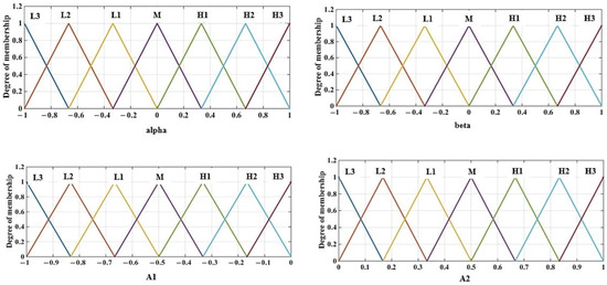
Figure 1.
Membership functions.

Table 1.
Fuzzy rules of .

Table 2.
Fuzzy rules of .
3.3. Corrected Controller
By using the suggested controller and estimator, the corrected is extracted as follows:
where presents the feed-forward compensation gain.
4. Experimental Results
In order to check the effectiveness of the proposed method, a series of experimental tests have been carried out in the laboratory on a PMSM motor. In this laboratory, a PMSM motor with the specifications presented in Table 3 has been tested. In the purposed test bench, a DSP TMS320F28335 has been used. In this configuration, LA-25 and LV 55 along with their signal conditioning circuits are employed to gauge the current and voltage, respectively. The speed sensor in this setup consists of an Omron Encoder E6B2-CWZ6C, with a resolution of 2000 pulses per rotation. Figure 2 shows the experimental test setup. These practical tests were conducted in two distinct scenarios to evaluate the performance of the proposed method under varying conditions and with different reference inputs. In all these tests, the proposed method has been compared with the performance of the conventional sliding mode control method. In the initial case, the efficiency of the suggested technique was assessed for step and ramp inputs. In the second instance, the effectiveness of the proposed design was evaluated under more challenging inputs.

Table 3.
PMSM machine specifications.
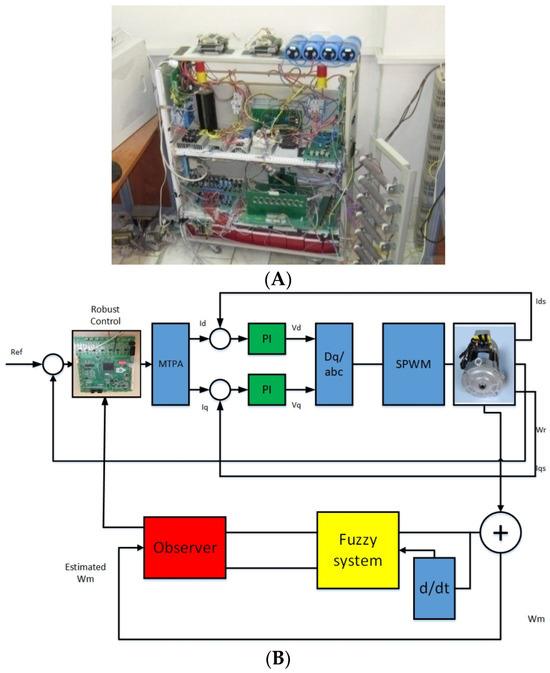
Figure 2.
(A) Test bench. (B) Closed-loop system.
4.1. Scenario 1
In this scenario, a simple step input is applied to the closed-loop system. This reference input is designed to step the motor speed to 200 rpm. In this reference input, the performance of the proposed control to rotate the motor in the reverse direction is checked. Figure 3 shows the performance of the desired method per step input in the first scenario. As illustrated in this figure, the proposed control structure effectively follows the desired input in both directions of rotation, demonstrating high accuracy in tracking the reference speed. According to this figure, in transient times and when the reference rate has a jump, the proposed method converges to the reference value after 0.15 s, while the conventional sliding method converges to the reference value after 0.75 s. Also, the proposed structure has an error of less than 0.5 RPM, while the conventional SMC shows a tracking error of 1.5 RPM. The main reason for the greater accuracy of the proposed method compared to the conventional SMC is that the proposed method removes both the effects of disturbances and the uncertainties of the model simultaneously using the robust controller and the H-infinity mechanism. Furthermore, the resilience of the entire control structure to load changes is enhanced through the implementation of the modified load torque observer. On the other hand, the conventional sliding controller only makes the system partially resistant to the uncertainties of the model, and the chattering phenomenon has a negative effect on the error of the conventional SMC.
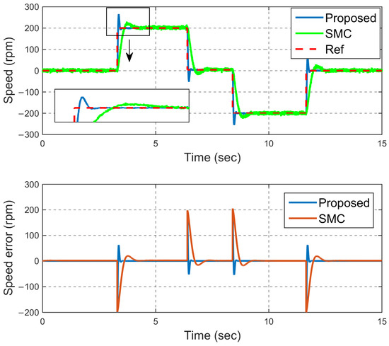
Figure 3.
Speed tracking (step—scenario #1).
To validate the performance of the proposed control structure in the transient state, a ramp input is applied to the closed-loop system in two different directions. Figure 4 shows the performance of the proposed method and the SMC method in tracking the input of the ramp reference. As is clear from this figure, the proposed method has been able to have an error of less than 1 rpm in the reference input tracking in the transient mode, while the conventional SMC method has a tracking error of about 9 rpm in transient mode. This confirms that the proposed method can rapidly converge to and track the reference input during continuous changes, while the conventional SMC method demonstrates a delay in following the reference input. The noteworthy point is that in all these scenarios, both methods have a little distortion, which is caused by the switching phenomenon in the motor drive. However, in the conventional SMC method, due to the chattering phenomenon, these fluctuations are more intense and reduce the accuracy of the control method. Figure 5 also shows the q-axis current for the step reference inputs. According to these figures, the amount of current in this axis is reasonable, which confirms the feasibility of the proposed control method. The estimation of the load torque using the proposed FASMO is shown in Figure 6. As is clear from this figure, the proposed FASMO estimates the load torque with no chattering.
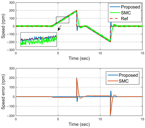
Figure 4.
Speed tracking (ramp—scenario #1).
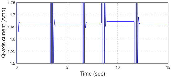
Figure 5.
Q-axis current (step—scenario #1).
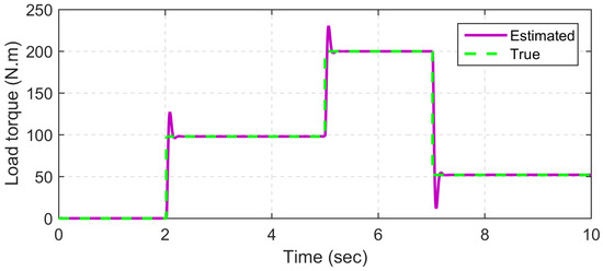
Figure 6.
Load torque estimation.
4.2. Scenario 2
In this scenario, an attempt has been made to measure the performance of the desired method for more complex inputs. For this reason, first, an input is applied in the form of increasing steps in the control loop. In this scenario, the reference input increases three consecutive steps from zero to 300 rpm and returns to zero again from 300 rpm. This input is designed to check the effectiveness of the proposed control structure for sudden jumps during motor movement. Figure 7 compares the tacking diagram of the proposed method and the conventional SMC method for this reference input. According to this figure, the proposed method has high accuracy, and its tracking error is less than 0.25 rpm, while the conventional SMC method shows a tracking error of about 2 rpm. In addition, during jumps that occur in the reference speed, the presented method can follow the reference input in less than 0.2 s. This is while the conventional SMC method succeeds in following the reference method after 1 s after reference speed jumps.
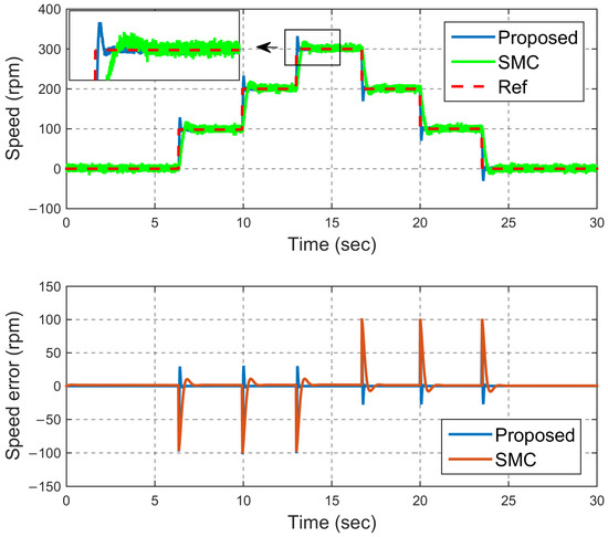
Figure 7.
Speed tracking (step—scenario #2).
However, this reference input is insufficient to assess the response of the proposed method in transient states under more complex conditions. To address this, a reference input consisting of a sequential combination of steep ramps is introduced to the closed-loop system. Figure 8 compares the response of the presented method and the conventional SMC method for this reference input. According to this figure, the conventional SMC method has a tracking error of 10 rpm, while the presented method can follow the ramp reference input with an error of about 1.2 rpm. This issue confirms the good performance of the proposed method even in transient states and during reference speed changes. The reason for this is the increase in the multifaceted resistance of the method in question against model uncertainties, disturbances, and sudden load changes. As in the previous scenario, Figure 9 also shows the Q-axis current for the motor. According to its logical value, it is possible to understand the feasibility of the proposed method. Figure 10 indicates the voltage diagram in both scenarios for step inputs. According to this figure, the value of the voltage confirms the feasibility of the proposed controller. It is worth mentioning that the jumps in this figure occurred at the step times, which is reasonable due to the sudden change in the reference value.
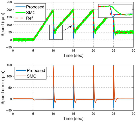
Figure 8.
Speed tracking (ramp—scenario #2).
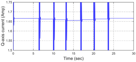
Figure 9.
Q−axis current (step—scenario #2).
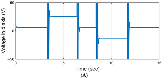
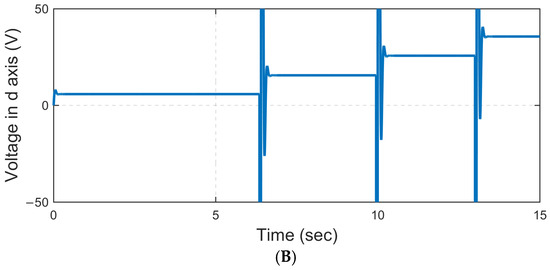
Figure 10.
D−axis voltage (step—(A) scenario 1 and (B) scenario 2).
The proposed controller is based on robust state feedback and, unlike SMC, does not have any signal discontinuity. Therefore, it does not cause any vibration in the motor. In addition, this scheme also reduces the effects of other disturbing signals, such as disturbances.
In addition, the proposed estimator is from sliding mode observers (SMOs), which are robust against model uncertainties. But the conventional SMOs have chattering in their response, and this paper solves this problem. To be more specific, by using a fuzzy system, the switching gain of the proposed estimator has been adapted, and in this way the chattering is eliminated. In other words, by the design of a fuzzy system, the proposed method tried to reduce chattering effects to a great extent, and as a result, motor vibrations will be very minor.
In addition to the comparison with the SMC, the performance of the proposed method has been compared to the conventional state feedback control. The result of this comparison is indicated in Figure 11. As is clear from Figure 11, and as is shown in scenario 1, the proposed method is able to follow the reference speed of less than 0.15 s with an error of 0.5 rpm. While the conventional state feedback control does not have a good performance, it has a prolonged convergence time and approximately cannot converge to the reference value. To be more specific, the conventional state feedback control is not robust against model uncertainties, disturbances, and load changes. So, it cannot have an acceptable performance subject to the uncertain model and reference input. For further comparison, the proposed method has been compared to two other methods in Table 4.
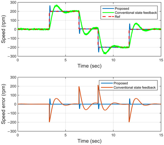
Figure 11.
Comparison to the conventional state feedback control.

Table 4.
Comparison of proposed method to other control methods.
The proposed method be extended to uncertain nonlinear systems, such as reference [33], with the following conditions. The nonlinear term should have the Lipschitz property. The uncertainty term should have the Lipschitz property or norm-bounded property. The uncertainty term should be additive with state equations.
5. Conclusions
In this paper, a super robust solution for this issue has been introduced, and a robust observer-based speed control for PMSM has been proposed. Model uncertainties and disturbances have been considered in the nonlinear dynamics of the PMSM, and in the proposed method, the uncertainties fit the Lipschitz condition; by using a robust state feedback control, the effects of the uncertainties were eliminated. In addition, considering and guaranteeing the Hꝏ conditions, the Lyapunov stability criteria were corrected and proven to eliminate the effect of the disturbances. Besides, a FASMO was presented to determine the load torque and was used for the control signal compensation. In this solution, the switching gain of the FASMO was adjusted utilizing a fuzzy system to mitigate chattering. The performance of the proposed method during two different scenarios was compared with the performance of a conventional SMC method. During the practical tests conducted in the laboratory in these two scenarios, it was found that the proposed method has a much higher convergence speed of as much as 8 sec and a much higher convergence accuracy of as much as 7 rpm than this method, both in the steady state and in the transient state.
Author Contributions
Conceptualization, H.T. and S.S.; methodology, B.M.A.; software, A.H.A.H.; validation, S.A. and H.C.; formal analysis, H.T.; investigation, B.M.A.; resources, S.S.; data curation, A.H.A.H.; writing—original draft preparation, H.C. All authors have read and agreed to the published version of the manuscript.
Funding
This research received no external funding.
Data Availability Statement
The raw data supporting the conclusions of this article will be made available by the authors on request.
Conflicts of Interest
The authors have disclosed that they do not have any conflicts of interest.
References
- Mei, M.; Cheng, S.; Li, L.; Mu, H.; Pei, Y. UKF-Based Observer Design for the Electric Brake Booster in Situations of Disturbance. Actuators 2023, 12, 94. [Google Scholar] [CrossRef]
- Wang, B.L.; Cai, Y.; Song, J.C.; Liang, Q.K. A Singular Perturbation Theory-Based Composite Control Design for a Pump-Controlled Hydraulic Actuator with Position Tracking Error Constraint. Actuators 2023, 12, 265. [Google Scholar] [CrossRef]
- Wang, L.; Zhao, J.; Zheng, Z. Robust speed tracking control of permanent magnet synchronous linear motor based on a discrete-time sliding mode load thrust observer. IEEE Trans. Ind. Appl. 2022, 58, 4758–4767. [Google Scholar] [CrossRef]
- Accetta, A.; Cirrincione, M.; Pucci, M.; Sferlazza, A. Feedback linearization based nonlinear control of SynRM drives accounting for self-and cross-saturation. IEEE Trans. Ind. Appl. 2022, 58, 3637–3651. [Google Scholar] [CrossRef]
- Aiso, K.; Akatsu, K. High speed SRM using vector control for electric vehicle. CES Trans. Electr. Mach. Syst. 2020, 4, 61–68. [Google Scholar] [CrossRef]
- Dang, H.L.; Kwak, S. Review of health monitoring techniques for capacitors used in power electronics converters. Sensors 2020, 20, 3740. [Google Scholar] [CrossRef]
- Nasr, A.; Gu, C.; Bozhko, S.; Gerada, C. Performance enhancement of direct torque-controlled permanent magnet synchronous motor with a flexible switching table. Energies 2020, 13, 1907. [Google Scholar] [CrossRef]
- Wang, X.; Wang, Z.; Xu, Z.; Cheng, M.; Hu, Y. Optimization of torque tracking performance for direct-torque-controlled PMSM drives with composite torque regulator. IEEE Trans. Ind. Electron. 2020, 67, 10095–10108. [Google Scholar] [CrossRef]
- Sabouni, E.; Merah, B.; Bousserhane, I.K. Adaptive backstepping controller design based on neural network for pmsm speed control. Int. J. Power Electron. Drive Syst. 2021, 12, 1940. [Google Scholar] [CrossRef]
- Zhang, L.; Ma, J.; Wu, Q.; He, Z.; Qin, T.; Chen, C. Research on PMSM speed performance based on fractional order adaptive fuzzy backstepping control. Energies 2023, 16, 6922. [Google Scholar] [CrossRef]
- Zhou, S.T.; Ma, J.Q.; Chen, C.S.; Qin, T.; He, Z.Q.; Wu, Q.M.; Liu, H.J.; Li, Y.J. The Speed Characters of PMSM with Advanced Precise Feedback Linearization Controller. J. Electr. Eng. Technol. 2024, 1–9. [Google Scholar] [CrossRef]
- Yi, P.; Wang, X.; Chen, D.; Sun, Z. PMSM current harmonics control technique based on speed adaptive robust control. IEEE Trans. Transp. Electrif. 2021, 8, 1794–1806. [Google Scholar] [CrossRef]
- Xu, B.; Zhang, L.; Ji, W. Improved non-singular fast terminal sliding mode control with disturbance observer for PMSM drives. IEEE Trans. Transp. Electrif. 2021, 7, 2753–2762. [Google Scholar] [CrossRef]
- Ünsal, S.; Aliskan, I. Investigation of performance of fuzzy logic controllers optimized with the hybrid genetic-gravitational search algorithm for PMSM speed control. Autom. Časopis Za Autom. Mjer. Elektron. Računarstvo I Komun. 2022, 63, 313–327. [Google Scholar] [CrossRef]
- Masoud, U.M.M.; Tiwari, P.; Gupta, N. Designing of an enhanced fuzzy logic controller of an interior permanent magnet synchronous generator under variable wind speed. Sensors 2023, 23, 3628. [Google Scholar] [CrossRef]
- Abdulghani, M.M.; Al-Aubidy, K.M.; Ali, M.M.; Hamarsheh, Q.J. Wheelchair neuro fuzzy control and tracking system based on voice recognition. Sensors 2020, 20, 2872. [Google Scholar] [CrossRef] [PubMed]
- Shanthi, R.; Kalyani, S.; Devie, M. Design and performance analysis of adaptive neuro-fuzzy controller for speed control of permanent magnet synchronous motor drive. Soft Comput. 2021, 25, 1519–1533. [Google Scholar] [CrossRef]
- Hoai, H.K.; Chen, S.C.; Chang, C.F. Realization of the neural fuzzy controller for the sensorless PMSM drive control system. Electronics 2020, 9, 1371. [Google Scholar] [CrossRef]
- Gao, P.; Zhang, G.; Lv, X. Model-free hybrid control with intelligent proportional integral and super-twisting sliding mode control of PMSM drives. Electronics 2020, 9, 1427. [Google Scholar] [CrossRef]
- Liu, J.; Yang, J.; Li, S.; Wang, X. Single-loop robust model predictive speed regulation of PMSM based on exogenous signal preview. IEEE Trans. Ind. Electron. 2023, 70, 12719–12729. [Google Scholar] [CrossRef]
- Kim, D.J.; Kim, B. Linear Matrix Inequality-Based Robust Model Predictive Speed Control for a Permanent Magnetic Synchronous Motor with a Disturbance Observer. Energies 2024, 17, 869. [Google Scholar] [CrossRef]
- Azizi Moghaddam, H.; Rezaei, O.; Vahedi, A.; Saeidi, M.; Ehsani, M. A continuous control set of the model predictive controller of PMA-SynRM machine for high-performance flywheel energy storage system. Int. J. Dyn. Control. 2022, 10, 1553–1566. [Google Scholar] [CrossRef]
- Chen, L.; Zhang, H.; Wang, H.; Shao, K.; Wang, G.; Yazdani, A. Continuous adaptive fast terminal sliding mode-based speed regulation control of PMSM drive via improved super-twisting observer. IEEE Trans. Ind. Electron. 2023, 71, 5105–5115. [Google Scholar] [CrossRef]
- Yang, T.; Deng, Y.; Li, H.; Sun, Z.; Cao, H.; Wei, Z. Fast integral terminal sliding mode control with a novel disturbance observer based on iterative learning for speed control of PMSM. ISA Trans. 2023, 134, 460–471. [Google Scholar] [CrossRef] [PubMed]
- Zhang, X.; Wang, Z. Simple robust model predictive current control for PMSM drives without flux-linkage parameter. IEEE Trans. Ind. Electron. 2022, 70, 3515–3524. [Google Scholar] [CrossRef]
- Lin, F.J.; Chiu, S.L. Adaptive fuzzy sliding mode control for PM synchronous servo motor drives. IEE Proc. Control Theory Appl. 1998, 145, 63–72. [Google Scholar] [CrossRef]
- Xu, W.; Junejo, A.K.; Tang, Y.; Shahab, M.; Habib, H.U.R.; Liu, Y.; Huang, S. Composite speed control of PMSM drive system based on finite time sliding mode observer. IEEE Access 2021, 9, 151803–151813. [Google Scholar] [CrossRef]
- Hu, J.; Liu, L.; Ma, D.W.; Ullah, N. Adaptive nonlinear feedback control of chaos in permanent-magnet synchronous motor system with parametric uncertainty. Proc. Inst. Mech. Eng. Part C 2015, 229, 2314–2323. [Google Scholar] [CrossRef]
- Jia, L.; Li, Y.; Du, J.; Yuan, S. Robust L2/L∞ control for uncertain singular systems with time varying delay. Prog. Nat. Sci. 2008, 18, 1015–1021. [Google Scholar]
- Abdissa, C.M. Improved model predictive speed control of a PMSM via Laguerre functions. Math. Probl. Eng. 2024, 2024, 5562771. [Google Scholar] [CrossRef]
- Mohd Zaihidee, F.; Mekhilef, S.; Mubin, M. Robust speed control of PMSM using sliding mode control (SMC)—A review. Energies 2019, 12, 1669. [Google Scholar] [CrossRef]
- Chen, Y.T.; Yu, C.S.; Chen, P.N. Feedback linearization based robust control for linear permanent magnet synchronous motors. Energies 2020, 13, 5242. [Google Scholar] [CrossRef]
- Ruan, Z.; Hu, J.; Mei, J. Robust optimal triple event-triggered intermittent control for uncertain input-constrained nonlinear systems. Commun. Nonlinear Sci. Numer. Simul. 2024, 129, 107718. [Google Scholar] [CrossRef]
Disclaimer/Publisher’s Note: The statements, opinions and data contained in all publications are solely those of the individual author(s) and contributor(s) and not of MDPI and/or the editor(s). MDPI and/or the editor(s) disclaim responsibility for any injury to people or property resulting from any ideas, methods, instructions or products referred to in the content. |
© 2024 by the authors. Licensee MDPI, Basel, Switzerland. This article is an open access article distributed under the terms and conditions of the Creative Commons Attribution (CC BY) license (https://creativecommons.org/licenses/by/4.0/).