Article

Active Disturbance Rejection Control for the Trajectory Tracking of a Quadrotor

by
Mario Ramírez-Neria
1,†,
Alberto Luviano-Juárez
2,†,
Jaime González-Sierra
3,*,†,
Rodrigo Ramírez-Juárez
4,
Joaquín Aguerrebere
1 and
Eduardo G. Hernandez-Martinez
1
1
Institute of Applied Research and Technology, Universidad Iberoamericana Ciudad de México, Prolongación Paseo de la Reforma 880, Colonia Lomas de Santa Fe, Mexico City 01219, Mexico
2
Unidad Profesional Interdisciplinaria en Ingeniería y Tecnologías Avanzadas, Instituto Politécnico Nacional, Av. IPN 2580, Col. Barrio La Laguna Ticomán, Ciudad de México 07340, Mexico
3
Unidad Profesional Interdisciplinaria de Ingeniería Campus Hidalgo, Instituto Politécnico Nacional, Carretera Pachuca—Actopan Kilómetro 1+500, Distrito de Educación, Salud, Ciencia, Tecnología e Innovación, San Agustín Tlaxiaca 42162, Mexico
4
Facultad de Estudios Superiories Cuautitlán Campo 4, Universidad Nacionacional Autonoma de Mexico, Carretera Cuautitlán—Teoloyucán Kilómetro 2+500, San Sebastian Xhala, Cuautitlá Izcalli 54714, Mexico
*
Author to whom correspondence should be addressed.
These authors contributed equally to this work.
Actuators 2024, 13(9), 340; https://doi.org/10.3390/act13090340
Submission received: 1 July 2024 / Revised: 19 August 2024 / Accepted: 2 September 2024 / Published: 5 September 2024
(This article belongs to the Special Issue Dynamics and Control of Underactuated Systems)

Abstract

:
In the last decade, quadrotors have gained popularity among industry and academia due to their capabilities and the various applications in which they can be found. In addition to the above, because this is an underactuated system, researchers have found it a great challenge to control. Despite this, there is a wide variety of methodologies in the literature to control this type of system. Based on the above, this work proposed an alternative to trajectory tracking control for quadrotor unmanned aerial vehicles (UAV). The problem was divided into two main control loops: an outer control loop for the position coordinates, tackled through linear active disturbance rejection controllers (ADRC), and an inner control loop related to the orientation variables, addressed via robust proportional-integral-differential (PID) controllers. Furthermore, a generalized proportional integral observer (GPIO) was implemented to estimate the velocity and internal and external disturbances; therefore, the control strategy only depended on the attitude (position and orientation) quadrotor measurements. Then, the control performance was tested through numerical simulations and experimental tests, including wind disturbance inputs.

1. Introduction

An unmanned aerial vehicle (UAV) is a mobile robot that moves through the air autonomously; it can fly with little or no human intervention. They have emerged as a technological tool that has allowed the development of diverse applications that are dangerous or difficult for humans to realize [1,2,3].
Among the diverse range of UAVs, quadrotor drones, also known as quadcopters, have gained immense popularity in the past decade. Their unique ability to take off and land vertically, with their maneuverability and hovering capability, has made them a favorite for various applications and services in industrial sectors such as logistics, agriculture, environmental monitoring, and sanitization, among others [4,5,6,7,8,9,10]. However, the underactuated nature of these systems and the intricate relationship between translational and rotational dynamics present a formidable challenge for researchers in controlling their position along a desired trajectory. For example, in [11], the authors reviewed different methodologies for controlling multi-rotor aerial robot systems and pointed out that most research has focused on proving the theory rather than the feasibility of the controller itself, since experiments with real robots raise several problems that directly affect the controllers. This complexity underscores the need for innovative and robust control strategies, such as the one proposed in this work.
The vast literature on drone trajectory control is a testament to the complexity of this challenge. For example, in [12,13], the authors proposed the basic proportional-integral-derivative (PID) technique to control quadrotor motion. In a similar context, the authors in [14] implemented a PID approach with a backstepping methodology, and in [15], the authors used a nested saturation algorithm. Nevertheless, quadrotor drones are susceptible to environmental disturbances impacting their performance in practical applications. These disturbances, which can arise from Coriolis forces, friction, aerodynamic coefficients, inertia moments, or unmodeled dynamics, underscore the need for a robust control strategy to handle them effectively. To overcome this problem, a diversity of robust control strategies have been designed, developed, and studied, such as sliding mode control (SMC) [16,17,18,19,20], H [21,22] and backstepping with SMC [23,24,25,26], among other methodologies [27].
One concept that has stood out and gained popularity among researchers and academia in recent years is active disturbance rejection control (ADRC) [28,29], which is based on representing the system as a disturbed chain of integrators, where the total disturbance represents all the internal and external disturbing effects. Such perturbations are estimated using an extended state observer (ESO) and further canceled out in the control law.
Despite being a widely studied topic, research areas continue to emerge as technology advances, for example, fault estimation diagnosis [30,31,32], estimation of unknown states or disturbances [33,34], and collision avoidance [35,36], among others. Nevertheless, this introduction is focused on those related to the purpose of this work, i.e., robust tracking control by employing ADRC. Related work can be found in [37,38,39,40,41,42,43,44,45]. For instance, in [37], a cascade ADRC scheme for the attitude subsystem was presented, while a backstepping SMC scheme was developed for the position subsystem; in [38], the authors improved the ADRC by structurally designing an extended state observer, concluding that the improved ADRC can estimate disturbances faster and more accurately than the conventional ADRC. A robust nonlinear ADRC was designed in [39] to track a desired trajectory and solve the attitude control problem of a quadrotor; similarly, in [40], a robust control strategy for controlling the flight of a UAV with a passively (fixed) tilted hexacopter was presented, which is based on a robust extended-state observer to estimate and reject internal dynamics and external disturbances; a control law, based on a tracking differentiator, extended state observers, and state error feedback approaches, was designed in [41] to control the attitude and altitude of a quadrotor. In [42], an adaptive sliding-mode-based ADRC strategy was proposed for the altitude and attitude control of a quadrotor subjected to external disturbances. An ADRC application for quadrotor system stabilization and obstacle avoidance under external disturbances was proposed in [43]. A modified ADRC was designed in [44] to obtain high-performance quadrotor flight with the presence of external disturbances and input delays. The experimental results, with artificial external wind gusts as the disturbances, illustrated the approach’s effectiveness. Finally, in [45], the authors presented theoretical, simulation, and experimental results by applying ADRC for controlling the altitude of a quadrotor using an in-ground-effect model. Even though the ADRC methodology has been successfully implemented to control quadrotors, some of the cited works still need improvement. For example, in [43,44], the dynamic model only considered disturbances in the orientation dynamics; the control strategies depended on positions and velocity measurements in [43]; the control strategy was developed considering the linearization of the dynamic model in [44], and only the altitude of the quadrotor was considered in [45].
When ADRC is carried out for systems in trajectory tracking tasks, it is helpful to combine it with differential flatness-based controllers [46,47], in which a set of variables, denoted as flat outputs, can parametrize all the system variables in terms of flat outputs and their finite-order time derivatives. The last aspect allows us to derive a reference trajectory from the system’s natural tracking. Even when this approach was tackled in some contributions (see [48,49]), the reported flat output construction was too complex for real-time implementations. Since the flat outputs of a system are not unique, the flatness-based problem is still open, with practical alternatives (in the sense of their easiness of implementation) becoming essential.
Building on the existing body of knowledge and motivated by previous works, the highlights of this article are summarized as follows:
  • The proposed approach is based on two sets of ADRC control loops, one for tracking a reference in the z axis (denoted as a direct loop) and an additional loop to control the reference trajectories in the x , y plane. This action is indirectly performed, since it depends on the orientation control (indirect loop).
  • The orientation control design, a crucial aspect of our research, involves a comprehensive algebraic procedure. This procedure provides the dynamic relation between the x , y dynamics, the orientation control inputs, and the ADRC design, ensuring a robust and reliable system.
  • The scheme also considers the estimation and cancellation of external disturbances and internal perturbations, such as non-modeled dynamics of possible coupling effects through the ESO.
  • The proposal is not just theoretical. It was experimentally assessed in trajectory-tracking tasks, considering a fan that provided external perturbations. This practical assessment reaffirmed the applicability of our approach in real-world scenarios.
The outline of this work is as follows: Section 2 describes the problem statement and the dynamic model. Section 3 presents the design of the control strategy, together with the GPIO. Section 4 describes the numerical simulations and real-time experiments, while Section 5 discusses the results. Finally, Section 6 presents some concluding remarks and offers insights for future work.

2. Problem Statement

Consider the mathematical model of a quadrotor [50], described in Figure 1, where the vector ζ = x y z R 3 represents the position coordinates and the vector η = ψ θ ϕ R 3 stands for the orientation coordinates yaw, pitch, and roll, respectively, from the body frame B = { X b , Y b , Z b } with respect to an inertial frame I = { X I , Y I , Z I } . In this work, a cross-shaped configuration is considered; therefore, its dynamics are given as
x ¨ = F m sin ϕ sin ψ + cos ϕ cos ψ sin θ + ξ x ( t ) ,
y ¨ = F m cos ϕ sin ψ sin θ sin ϕ cos ψ + ξ y ( t ) ,
z ¨ = F m cos ϕ cos θ + ξ z ( t ) ,
η ¨ = τ + ξ η ( t ) ,
where m R is the mass of the quadrotor, F R is the thrust force, and τ = τ ψ τ θ τ ϕ R 3 is a vector of the control inputs. The terms ξ x , ξ y , ξ z , and ξ η = ξ ψ ξ θ ξ ϕ R 3 represent perturbations such as Coriolis forces, friction, aerodynamic coefficients, inertia moments, or unmodeled dynamics. It is worth mentioning that the term ξ z includes the gravity term g R .
Assumption 1.
The perturbations ξ j , for j = x , y , z , ψ , θ , ϕ , are smooth bounded signals. Therefore, real positive numbers exist K j such that sup t | ξ j | K j .
Assumption 2.
The disturbances ξ j can be modeled as a family of fixed-degree Taylor series polynomials of order h 1 , which satisfies d h d t h ξ j = d h d t h r j ( t ) 0 , where r j ( t ) is a residual term (see [51]).
The problem consists of designing a robust control strategy that drives the quadrotor to follow a desired time-varying trajectory, even with the presence of unknown disturbances, such that
lim t ζ ζ * η η * = 0 0 ,
where ζ * = x * y * z * R 3 is the vector of the desired positions, while η * = ψ * θ * ϕ * R 3 is the vector of the desired angles. For this purpose, a hierarchical strategy is proposed, where it is assumed that the rotation angles converge faster than the position coordinates. In this sense, the inner control loop, related to the orientation angles, can be directly solved through classic control schemes such as PID [52]. On the other hand, the outer control loop is tackled through algebraic manipulations and the ADRC approach.

3. Control Strategy

This section describes how the control inputs are obtained. In the first step, the control for the coordinate z is presented. Then, the control for the coordinates x and y is detailed. Finally, the control for the orientation angles is given.

3.1. Trajectory Tracking Control of z: A Direct ADRC Scheme

Using the ultra-local model approximation described in [53,54], one can consider that ξ ˙ z 0 . Then, defining z 1 = z and z 2 = z ˙ , system (3) can be rewritten in state-space as
z ˙ 1 = z 2 ,
z ˙ 2 = F m cos ϕ cos θ + ξ z .
Remark 1.
Notice that in system (6), it has been assumed that a piece-wise function approximates the generalized disturbance input. However, the complexity of the disturbance may imply the use of a more significant order approximation, as stated in Assumption 2.
Based on (5) and (6), the following GPIO [55] is proposed as
z ^ ˙ 1 = z ^ 2 + λ 2 z ( z 1 z ^ 1 ) ,
z ^ ˙ 2 = F m cos ϕ cos θ + ξ ^ z + λ 1 z ( z 1 z ^ 1 ) ,
ξ ^ ˙ z = λ 0 z ( z 1 z ^ 1 ) ,
where λ i z > 0 is the gain observer, for i = 0 , 1 , 2 . The observer injection error is defined as e ˜ z : = z 1 z ^ 1 , thus, from (5) and (6) and (7)–(9), it is easy to see that the injection error satisfies the following linear dominant dynamics:
e ˜ z + λ 2 z e ˜ ¨ z + λ 1 z e ˜ ˙ z + λ 0 z e ˜ z = 0 .
For tuning the observer gains, the characteristic polynomial of the observer error is matched with Hurwitz polynomials as [56]
s 3 + λ 2 z s 2 + λ 1 z s + λ 0 z = ( s 2 + 2 ζ z w n z + w n z 2 ) ( s + w n z ) ,
where ζ z is the desired damping coefficient and w n z is the desired natural frequency. Therefore, the injection gains are selected as λ 2 = 2 ζ z w n z + w n z , λ 1 = 2 ζ z w n z 2 + w n z 2 , and λ 0 = w n z 3 . By properly choosing the gain observers, λ i can guarantee the convergence to the estimated values, that is, z ^ 1 z , z ^ 2 z ˙ , and ξ ^ z ξ z [51].
Remark 2.
Another manner of tuning the gain observers was developed in [57], where all-pole systems can be constructed by adjusting a simple parameter.
The position error is e z = z z * , where z * is the desired altitude. Then, the error dynamics of e z are given by
e ¨ z = F m cos ϕ cos θ + ξ z z ¨ * ,
therefore, based on (7)–(9) and (11), the control input F is designed as
F = m cos ϕ cos θ z ¨ * k z 1 e z k z 2 e ^ z ξ ^ z ,
where e ^ z = z ^ 2 z ˙ * .
Theorem 1.
Let the control (12), along with the GPIO given in (7)–(9) be applied in system (11). Then, the position error e z will converge to a vicinity near the origin as t .
Proof. 
Let us define ϵ z = e z e ˙ z , then, substituting (12) into (11) yields the following state-space system
ϵ ˙ z = A z ϵ z + Z ( z ˜ 2 , ξ ˜ z ) ,
where A z = 0 1 k z 1 k z 2 , Z ( z ˜ 2 , ξ ˜ z ) = 0 k z 2 z ˜ 2 + ξ ˜ z is the perturbation term, with z ˜ 2 = z 2 z ^ 2 and ξ ˜ z = ξ z ξ ^ z . Note that if the gains k z 1 and k z 2 > 0 , matrix A z is Hurwitz. Furthermore, if the perturbation term Z ( z ˜ 2 , ξ ˜ z ) = 0 , the equilibrium point ϵ z = 0 is globally asymptotically stable. On the other, considering the perturbation term Z ( z ˜ 2 , ξ ˜ z ) , from [51] one knows that z ^ 2 z ˙ and ξ ^ z ξ z , which implies that z ˜ 2 and ξ ˜ z converge asymptotically to an arbitrary small vicinity near the origin. Moreover, from the result given in [58], one can conclude that the state z practically tracks the reference signal z * , in the sense that, for any σ > 0 , there exists a constant ε * such that for any ε ( 0 , ε * )
z z * σ uniformly in t t ε , ,
where t ε is an ε -dependent constant. In particular,
lim t sup z z * σ .    
Remark 3.
Note that control (12) presents a singularity when cos ϕ cos θ = 0 . This happens when ϕ or θ = ± π 2 . Since, in this work, aggressive maneuvers are not considered, the orientation angles ϕ, θ π 2 , π 2 which imply that cos ϕ cos θ 0 and singularity are avoided.

3.2. Trajectory Tracking Control of x , y : An Indirect ADRC Scheme

The latter analysis only involved the dynamics of z, which can be carried out through a direct control loop. The control design for the tracking task in the variables x , y involves a recursive design regarding the orientation control. In that sense, in the following procedure, a relation between the orientation angles and the x , y coordinates, which will be used for the design of a set of auxiliary control inputs, is denoted as u x , u y , which will provide reference signals for the orientation angles to then be controlled in an internal control loop. In this sense, substituting (12) into (1) and into (2), one has
x ¨ y ¨ = u z R ( ψ ) tan ϕ cos θ tan θ + ξ x ( t ) ξ y ( t ) ,
where u z = z ¨ * k z 1 e z k z 2 e ^ ˙ z ξ ^ z , and
R ( ψ ) : = sin ψ cos ψ cos ψ sin ψ .
The system (13) can be related to a control system in which the term u z R ( ψ ) can be stated as a nonlinear matrix control gain and the control vector is defined by tan ϕ cos θ tan θ . This relation is used to define a hierarchical control scheme consisting of the following loops:
  • An external control loop of ADRC nature involved in the trajectory tracking control of x , y , whose control input is θ and ϕ .
  • An internal control loop taking the control inputs obtained from the external control loop as reference states to be further controlled in the dynamics of (4).
  • Notice that the internal control loop is assumed to be fast enough to respect the time scale separation principle (see [59]).

3.2.1. External Control Loop Design

The following relation can be obtained from (13)
tan ϕ * cos θ * tan θ * = R ( ψ ) u z u x u y ,
where u x and u y are auxiliary control inputs.
Remark 4.
Note that if u z = 0 , (14) is singular. Nevertheless, lim t u z = z ¨ * ξ ^ z . Since z * and its time-derivatives are known, z * can be designed so that u z 0 .
Assuming that tan ϕ * cos θ * tan ϕ cos θ and tan θ * tan θ , then, substituting (14) into (13) one obtains the following system:
x ¨ y ¨ = u x u y + ξ x ( t ) ξ y ( t ) .
System (15) allows us to propose a flatness-based linear ADRC synthesis. Then, defining χ 1 = x y , χ 2 = x ˙ y ˙ , and considering the ultra-local model approximation for (15), again using one extended state for each disturbance input (as presented by the ADRC design to control the variable z and Assumption 2), that is χ ˙ 3 = ξ ˙ x ξ ˙ y 0 , then, system (15) can be rewritten as
χ ˙ 1 = χ 2 ,
χ ˙ 2 = u x y + χ 3 ,
where u x y = u x u y . Proposing the GPIO for (16) and (17), one has
χ ^ ˙ 1 = χ ^ 2 + λ 2 x y ( χ 1 χ ^ 1 ) ,
χ ^ ˙ 2 = u x y + χ ^ 3 + λ 1 x y ( χ 1 χ ^ 1 ) ,
χ ^ ˙ 3 = λ 0 x y ( χ 1 χ ^ 1 ) ,
where λ i x y R 2 × 2 is the matrix observer gain. The linear dominant dynamics of the injection errors, say e ˜ χ : = χ 1 χ ^ 1 , are given by
e ˜ χ + λ 2 x y e ˜ ¨ χ + λ 1 x y e ˜ ˙ χ + λ 0 x y e ˜ χ = 0 .
System (21) can be matched with Hurwitz polynomials with the same structure as those presented in (10), then, the injection errors are forced to be ultimately bounded, ensuring sufficiently accurate estimations to carry out the ADRC loops. By properly choosing the gain observers, λ i x y can guarantee the convergence of the estimated values, that is, χ ^ 1 χ 1 , χ ^ 2 χ 2 , and χ ^ 3 χ 3 . Let us define the position error as e χ = χ 1 χ * , where χ * = x * y * is the desired position, which is at least twice differentiable, then, the error dynamics are given as
e ¨ χ = u x y + χ 3 χ ¨ * .
Based on (18)–(20) and (22), the auxiliary control inputs are proposed as
u x y = χ ¨ * k x 1 0 0 k y 1 e χ k x 2 0 0 k y 2 e ^ χ χ ^ 3 ,
where e ^ ˙ χ = χ ^ 2 χ ˙ * , and the gains k x 1 , k x 2 , k y 1 , and k y 2 are positive.
Theorem 2.
Let the control (23), along with the GPIO given in (18)–(20), be applied in system (22). Then, the trajectory tracking error e χ is restricted to an ultimately bounded vicinity of the origin of the phase plane.

3.2.2. Internal Control Loop

From the external control loop (23) and the definition of the auxiliary control inputs u x , and u y , the reference values of the orientation variables θ , and ϕ , denoted by θ * and ϕ * , can be obtained from (14) as follows:
θ * = arctan u x cos ψ + u y sin ψ u z ,
ϕ * = arctan cos θ * u z u x sin ψ u y cos ψ .

3.3. Orientation Control

The orientation error is defined as e η = η η * , whose dynamics are given as e ¨ η = τ + p η , where p η = ξ η η ¨ * is the total perturbation. Let us define e η 1 = e η , e η 2 = e ˙ η and considering Assumption 2, that is, p ˙ η 0 , then, one can obtain the following state-space system:
e ˙ η 1 = e η 2 ,
e ˙ η 2 = τ + p η .
A GPIO is proposed for system (26) and (27) as
e ^ ˙ η 1 = e ^ η 2 + λ 2 η ( e η 1 e ^ η 1 ) ,
e ˙ ^ η 2 = τ + p ^ η + λ 1 η ( e η 1 e ^ η 1 ) ,
ξ ^ ˙ η = λ 0 η ( e η 1 e ^ η 1 ) ,
where λ i η R 3 × 3 is the matrix observer gain. The linear dominant dynamics of the injection errors, defined as e ˜ η : = e η 1 e ^ η 1 , are given by
e ˜ η + λ 2 η e ˜ ¨ η + λ 1 η e ˜ ˙ η + λ 0 η e ˜ η = 0 .
System (31) can be matched with Hurwitz polynomials with the same structure as those presented in (10), then, the injection errors are forced to be ultimately bounded, ensuring sufficiently accurate estimations to carry out the ADRC loops. By properly choosing the gain observers, λ i η can guarantee the convergence of the estimated values, that is, e ^ η 1 e η , e ^ η 2 e ˙ η , and ξ ^ η ξ η . Based on the above, the control law for the orientation angles is given as
τ = κ 0 0 t e η d τ ¯ κ 1 e η κ 2 e ^ η 2 p ^ η ,
where κ 0 = diag { κ ψ 0 , κ θ 0 , κ ϕ 0 } , κ 1 = diag { κ ψ 1 , κ θ 1 , κ ϕ 1 } and κ 2 = diag { κ ψ 2 , κ θ 2 , κ ϕ 2 } are definite positive matrices that correspond to the control gains.
Theorem 3.
Let the control (32), along with the GPIO given in (28)–(30), be applied in system (26) and (27). Then, the orientation error e η is restricted to an ultimately bounded vicinity of the origin of the phase plane.
Proof. 
The proofs of Theorems 2 and 3 are similar to the one presented for Theorem 1.  □
Remark 5.
It is worth mentioning that the controls (12), (23), (24), (25) and (32) only depend on the measurement of a quadrotor’s positions and orientations, since its velocities and disturbances are estimated through the GPIO.
Remark 6.
It must be clarified that the control law (32) only serves to make a numerical simulation comparison with another control strategy and determine its performance, because, practically, the control that is being sent to the quadrotor is the one obtained in (24) and (25).

4. Numerical Simulations and Real-Time Experiments

The first part of this section is dedicated to presenting the results of numerical simulations obtained by comparing the control strategy developed in this work and a technique based on sliding modes. Subsequently, the results practically obtained using a commercial quadrotor are described.

4.1. Numerical Simulations

The proposed control strategy’s performance was evaluated and compared with the continuous twisting (CT) robust control law defined in [60]. The simulations were implemented in MATLAB®-Simulink® R2017b (The MathWorks Inc., Natick, MA, USA) with a sampling time of 0.001 s using Euler’s integration method with m = 1 kg. The quadrotor’s initial condition was ζ ( 0 ) η ( 0 ) = 0 1 0 0 0 0 , while the desired trajectory was a Lissajous curve defined with the following parametric functions
x * = 2 sin ( 2 w t ) cos ( w t ) , y * = 2 sin ( 2 w t ) sin ( w t ) , z * = 0.5 sin ( w t ) + 5 , ψ * = 0.8 cos ( w t ) ,
with w = π 30 . The perturbations were defined as
ξ x = a x m x ˙ + 0.2 sin ( 0.2 t ) + 0.3 , ξ y = a y m y ˙ + 0.2 cos ( 0.4 t ) 0.3 , ξ z = a z m z ˙ 0.2 sin ( 0.2 t ) 0.3 , ξ ψ = a ψ ψ ˙ ϕ ˙ + 0.2 sin ( 0.5 t ) + 0.3 , ξ θ = a θ θ ˙ ϕ ˙ + 0.5 sin ( 0.3 t ) + 0.1 , ξ ϕ = a ϕ θ ˙ ψ ˙ 0.4 sin ( 0.2 t ) 0.4 ,
where a x = a y = a z = 0.01 , a ψ = I x I y I z , a θ = I z I x I y , a ϕ = I y I z I x , with I x = I y = 0.015 kg·m2, and I z = 0.03 kg·m2 as the inertia moments. The control gains were set as k z 1 = 5 , k z 2 = 4 , k x 1 = k y 1 = 5 , k x 2 = k y 2 = 3 , κ 0 = diag { 652.99 } , κ 1 = diag { 336.32 } , and κ 2 = diag { 48 } , while the observer parameters were set as ζ z = 4 , w n z = 35 , which yielded λ 2 z = 315 , λ 1 z = 11,025 , λ 0 z = 42,875 , λ 0 x y = diag { λ 0 z } , λ 1 x y = diag { λ 1 z } , λ 2 x y = diag { λ 2 z } , λ 0 η = diag { λ 0 z } , λ 1 η = diag { λ 1 z } , and λ 2 η = diag { λ 2 z } .
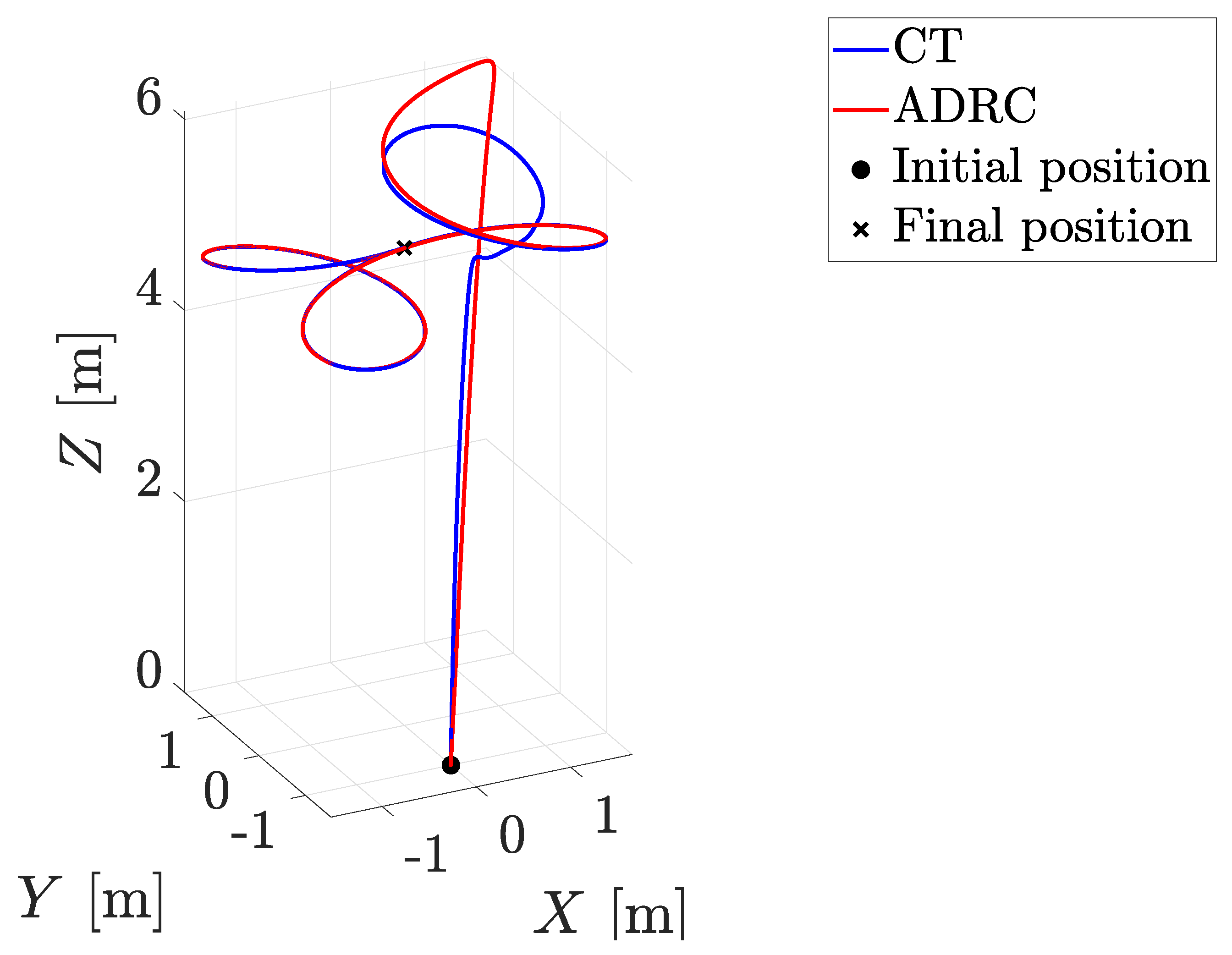
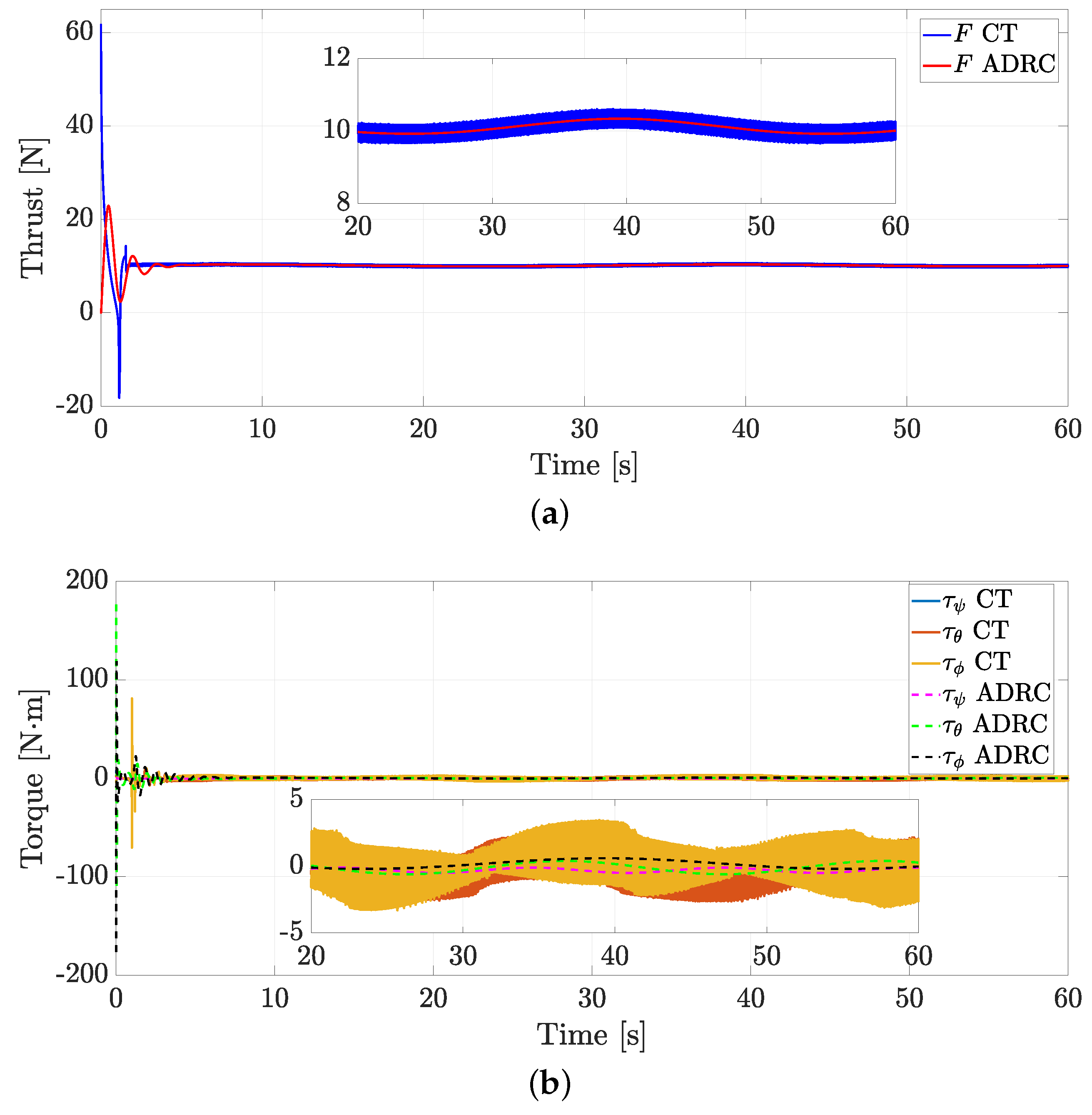
Figure 2 shows a motion comparison of the quadrotor in a 3 dimensional space, while Figure 3a,b present the thrust and the torques, respectively. One can note that the thrust and torques with the CT approach had high-frequency oscillations, which could lead to motor failure.
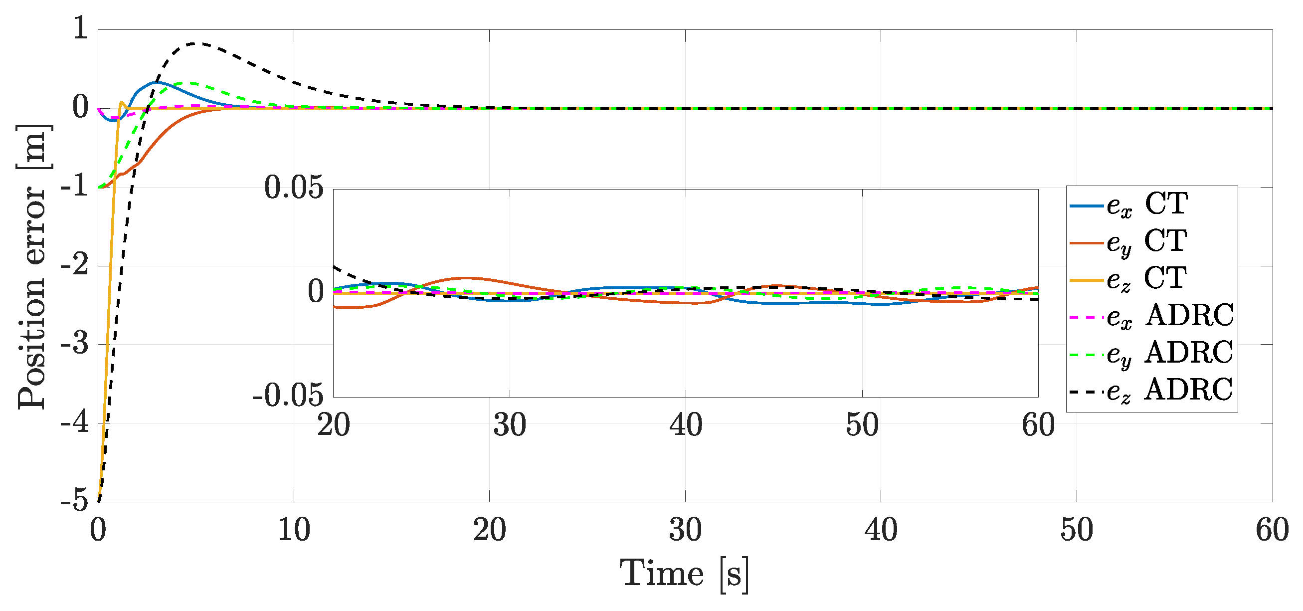
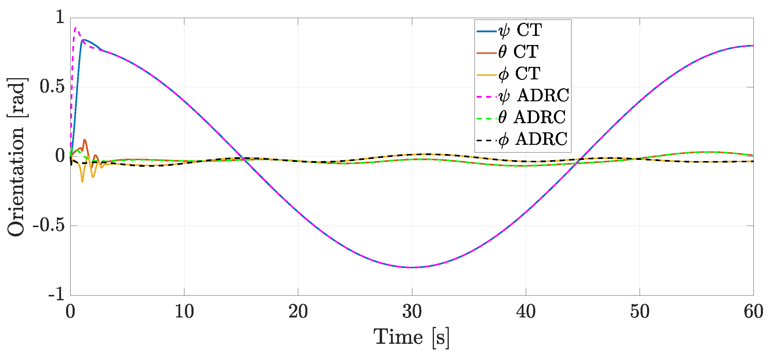
The position tracking error comparison is depicted in Figure 4, where it is evident that both strategies led the error to converge to zero. On the other hand, Figure 5 illustrates the orientation angle comparison.
To assess the overall performance, the following average RMS over a suitable receding-horizon time interval of finite length was calculated as
F R M S = 1 Δ t t Δ t t F 2 ( τ ¯ ) d τ ¯ 1 2 , τ R M S = 1 Δ t t Δ t t τ ( τ ¯ ) 2 d τ ¯ 1 2 ,
e ζ R M S = 1 Δ t t Δ t t e ζ ( τ ¯ ) 2 d τ ¯ 1 2 , e η R M S = 1 Δ t t Δ t t e η ( τ ¯ ) 2 d τ ¯ 1 2 ,
where e ζ = ζ ζ * , Δ t = 2 s is the time window width in which the corresponding signal is evaluated. From Figure 6a, one can note that the signals are similar; however, high-frequency oscillations still appeared in the CT approach. Furthermore, from Figure 6b, the ADRC methodology needed more energy to carry out the quadrotor motion.
Figure 7a depicts the position error index, where it is evident that the CT algorithm decreased to zero faster than the ADRC, while for Figure 7b, the transient response had a better performance using the ADRC methodology and converged faster to zero than the CT control.
Based on the results presented above, both strategies solved the trajectory-tracking problem of a quadrotor with external perturbations. However, it is essential to note that when using the CT, the control signals presented high-frequency oscillations, which can cause the motors to fail. In addition, the CT of [60] presented another restriction, that is, the angle ψ ( π 2 , π 2 ) , unlike the strategy presented in this work, where there is no restriction for this angle.

4.2. Real-Time Experiments

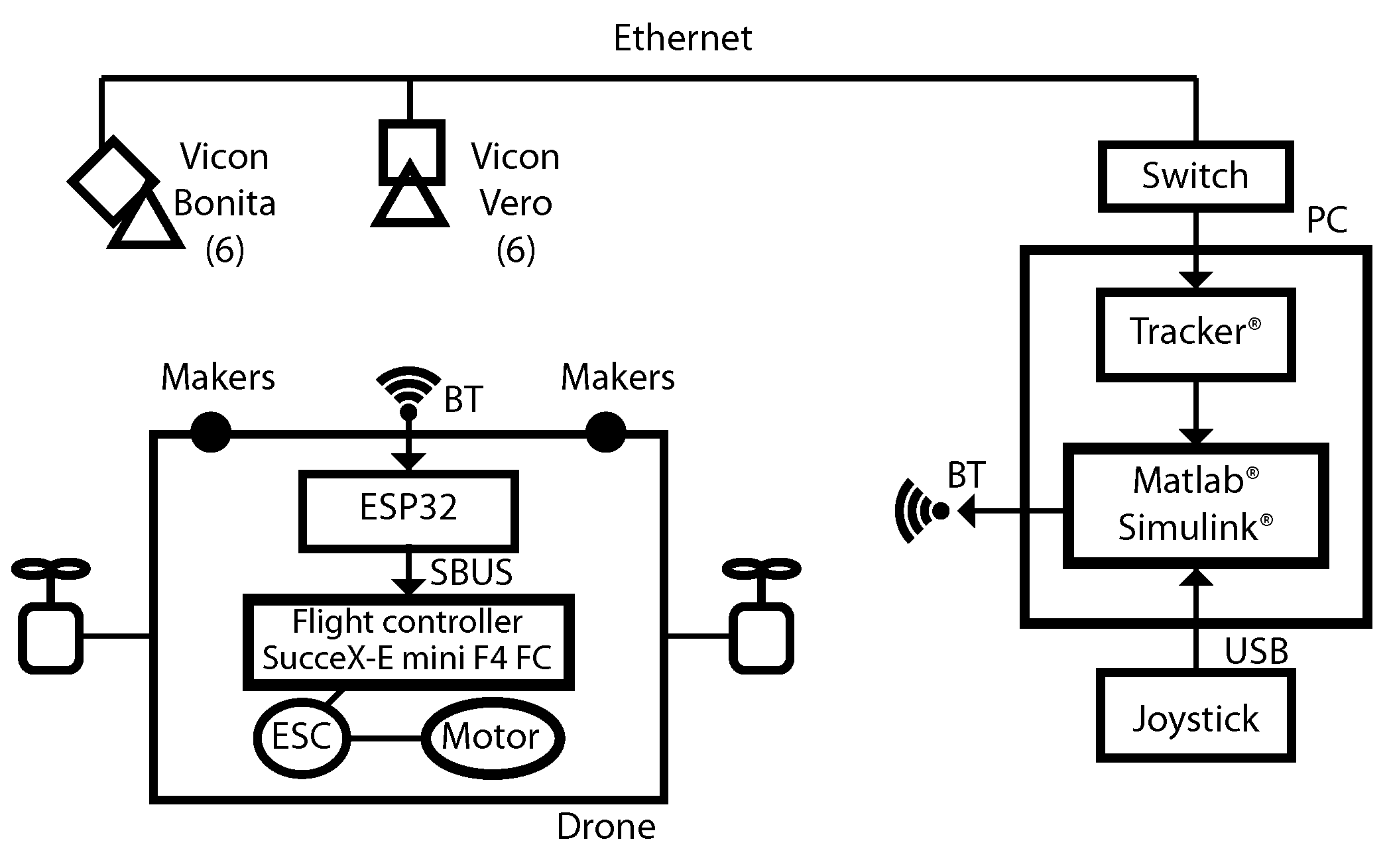
The control was implemented using an Iflight Quad© green hornet v2 (F6, Building B2, Galaxy IMC, Beixin Road,No.6, Zhongkai Avenue, Huizhou, China) shown in Figure 8. This system has 6 mm spherical reflective markers placed along the drone’s body and has 4 outrunner motors model XING-1408 3600 KV with 4 ESCs. Each motor has a three-blade propeller 5 cm in width. The flight controller is a SucceX-E mini F4 FC with serial communication to other electronic devices. The drone is powered by a 4 cells LiPO Lumenier© 1550 mAh. Figure 8 depicts the propellers protected by the frame with plastic materials and a smooth foam case.
The control implementation is described in Figure 9. The flight controller was connected by wired serial communication to an ESP32 microcontroller. This was a wireless packet receiver that received the desired angular setpoints from the computer through a Bluetooth communication via a Wi-Fi Bluetooth 5.2 PCIe adapter. Thus, the inner loop ran in the flight controller using manufacturer default orientation PID controllers, and the PID gains were adjusted through Betaflight Configurator v10.8 software. On the other hand, the outer loop for the position control used a VICON® Motion Capture System v3.10 (14 Minns Business Park, West Way OX2 0JB OXFORD, GBR) composed of 6 infrared cameras model Bonita and 6 cameras model Vero. The 12 cameras covered a volumetric workspace with dimensions of 6 m in length, 6 m in width, and 2 m in height. The resolution of the cameras was around 0.5 mm and 0.1 rad. The sample time for measurements was about 200 samples per second. All the cameras were connected to a switch by Ethernet and TCP/IP. The switch sent the camera’s data to a computer with an Intel i9 processor with 64 GB of RAM. The VICON® Tracker software v3.10 captured the position and rotation angles. The tracker sent the data to an application programmed in MATLAB®-Simulink® R2021 (The MathWorks Inc., Natick, MA, USA) [61]. MATLAB® software R2021 ran in real time with a sample time of 5 ms, the outer loop controller and observer were implemented in continuous time using the Simulink Desktop Real-TimeTM Toolbox, a fixed-step sample time was configured, and the ode4 Runge-Kutta solver algorithm was used. The computer executed the outer loop controller by sending the setpoints for the inner loop through Bluetooth.
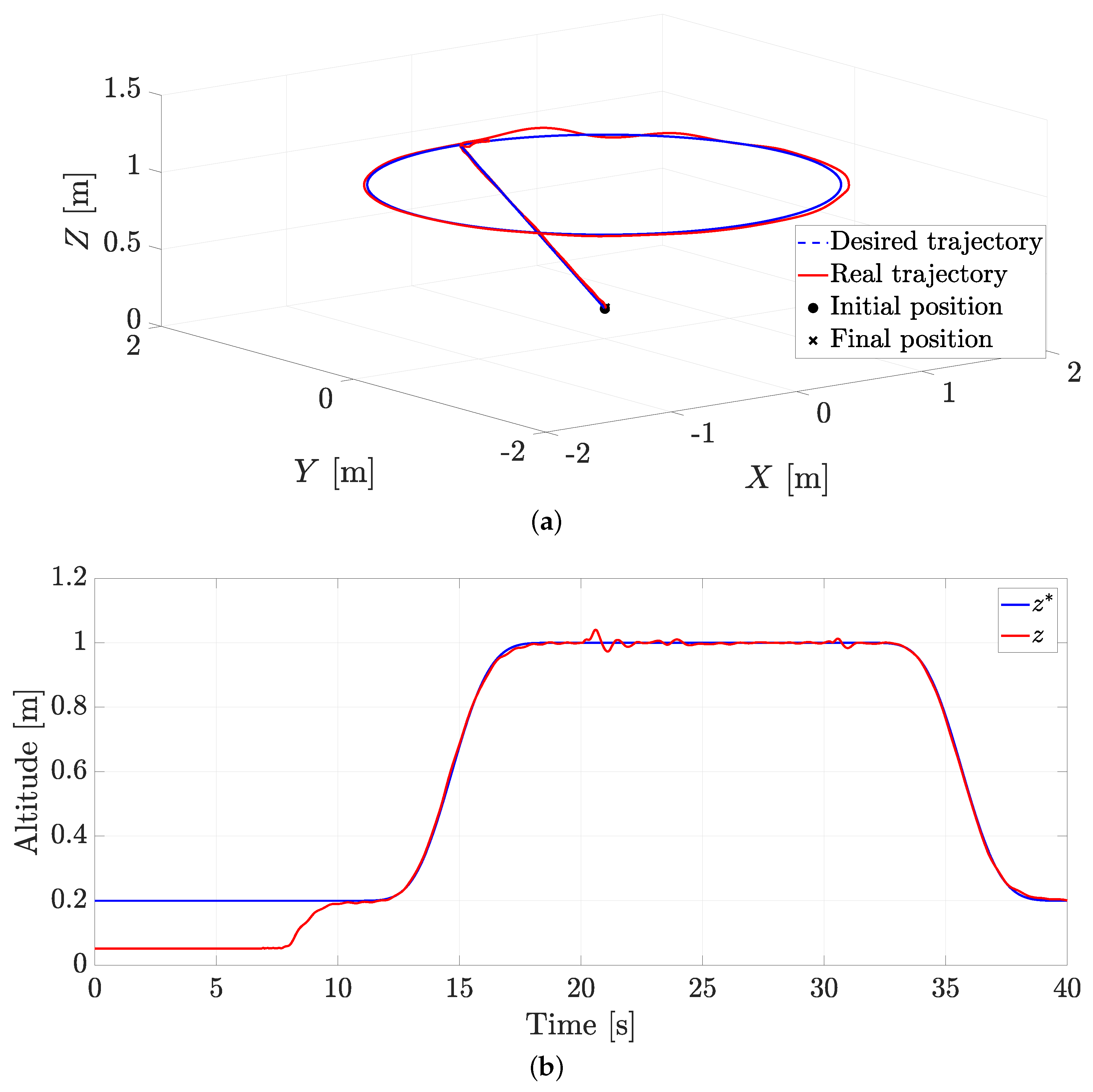
The desired trajectory z * was defined by implementing smooth interpolation polynomials. In that sense, in the first instance, the drone was at a height of 0.2 m and rose smoothly to a height of 1 m in 10 s. Subsequently, it remained at that height for 15 s and began its descent using another smooth interpolation polynomial. When the drone had reached the height of 1 m, a circular path in the X Y plane was defined, with the following parametric functions x * ( t 15 ) = sin 2 π 10 ( t 15 ) , y * ( t 15 ) = cos 2 π 10 ( t 15 ) . The desired yaw angle was established as a constant given by ψ * = π 4 . The model parameter for the dynamical system was m = 0.6 kg.
For the rotation inner-loop running in the flight controller, the control gains for the PID were set as κ 0 = diag { 90 , 90 , 85 } , κ 1 = diag { 30 , 46 , 42 } , and κ 2 = diag { 30 , 38 , 35 } . For the position outer-loop, the observer gains were set as ζ z = 4 , w n z = 35 , λ 0 z = 42,875, λ 1 z = 11,025, λ 2 z = 315 , λ 0 x y = diag { λ 0 z , λ 0 z } , λ 1 x y = diag { λ 1 z , λ 1 z } , λ 2 x y = diag { λ 2 z , λ 2 z } , λ 0 η = diag { λ 0 z , λ 0 z . λ 0 z } , λ 1 η = diag { λ 1 z , λ 1 z , λ 1 z } , and λ 2 η = diag { λ 2 z , λ 2 z , λ 2 z } ; while the control gains were set as k z 1 = 25 , k z 2 = 8 , k x 1 = k y 1 = 25 , and k x 2 = k y 2 = 9 .

4.3. Experiment without External Disturbances

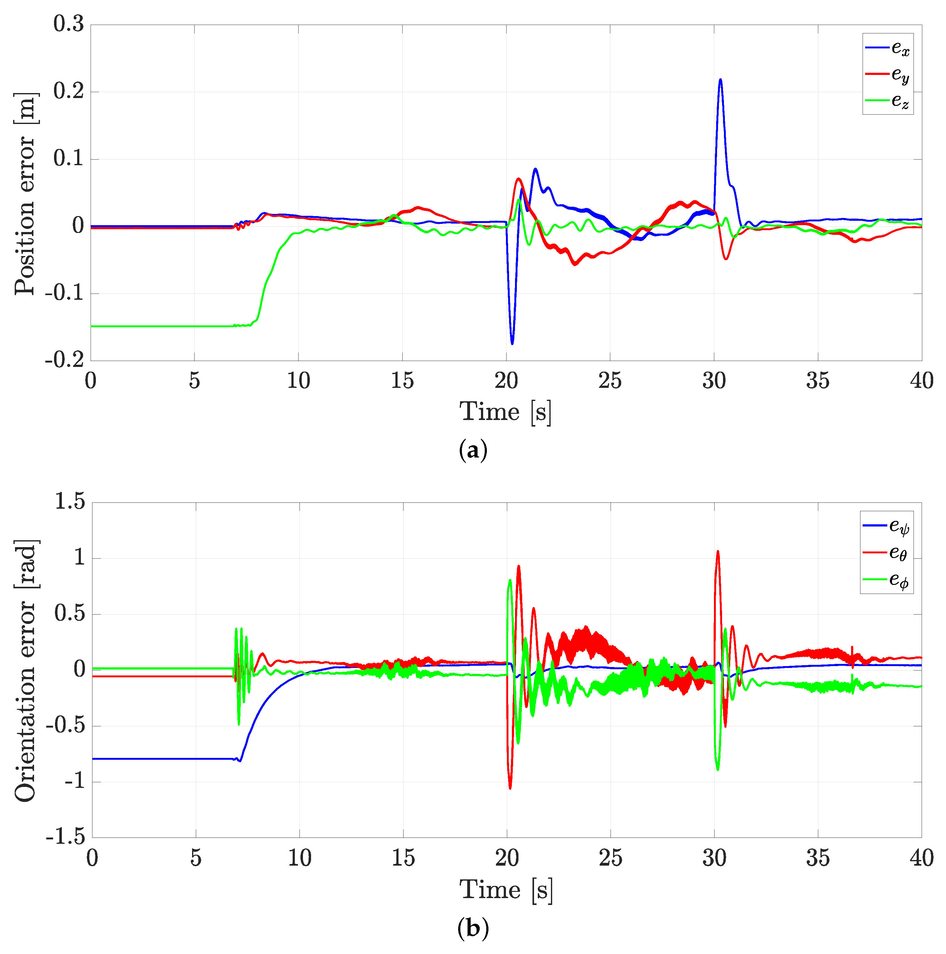
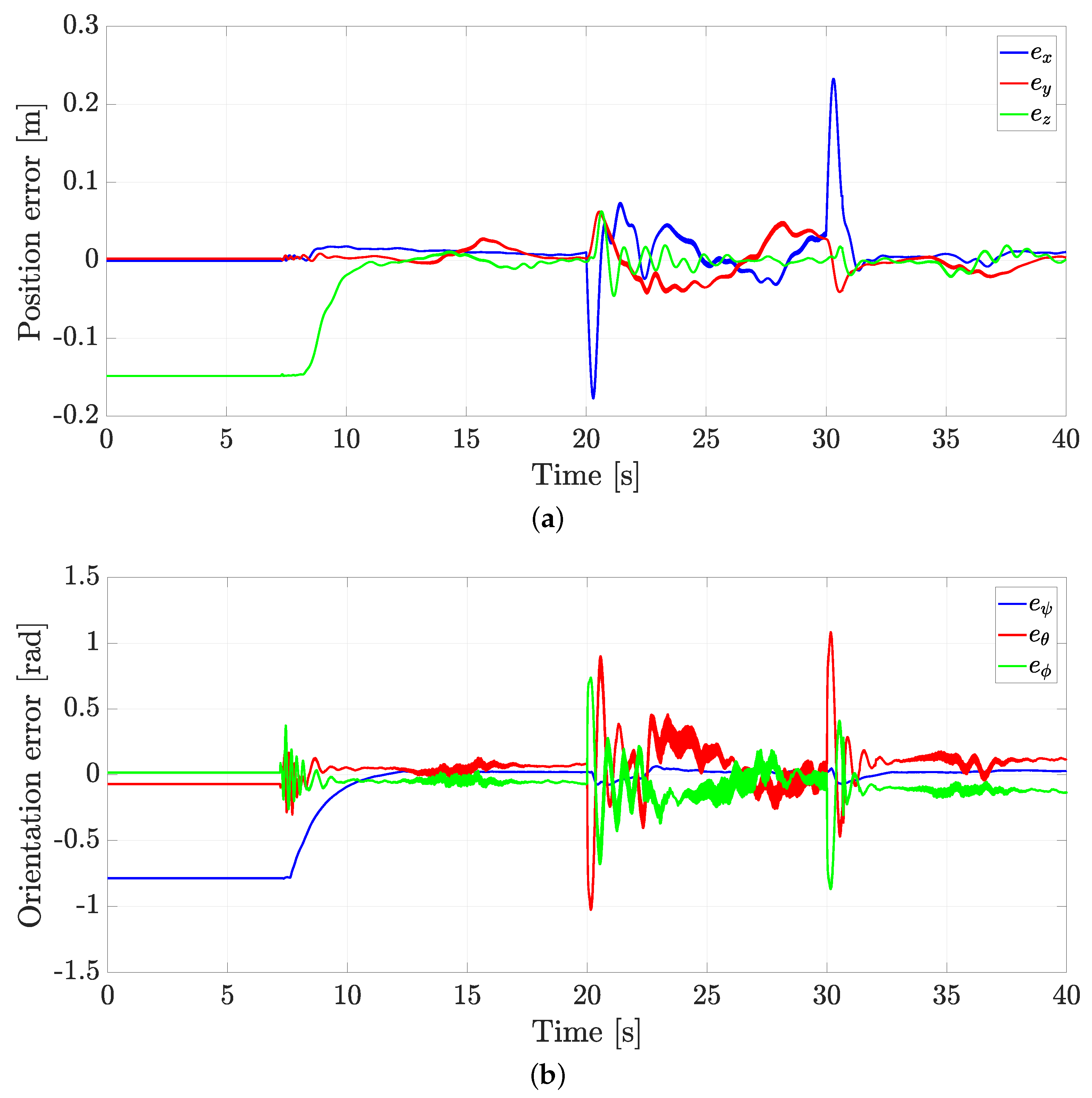
Figure 10a compares the desired trajectory and that performed by the quadcopter, while Figure 10b illustrates the trajectory tracking in the Z coordinate. It is worth pointing out that the quadrotor could achieve trajectory tracking. This is displayed in Figure 11, where both the position and orientation errors oscillate around zero.
From Figure 11, one can note that there were peaks of great amplitude at 20 s and 30 s. At t = 20 s, the controller gains caused the quadrotor to move abruptly to follow the desired trajectory. Similarly, at t = 30 s, the quadrotor had a certain inertia that was reflected when it finished following the trajectory in the plane.
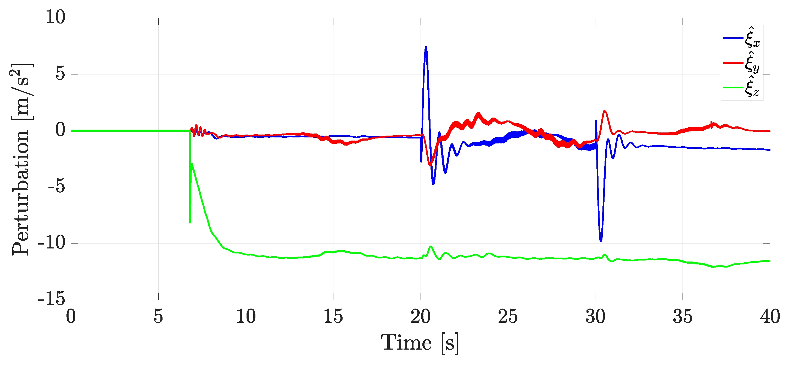
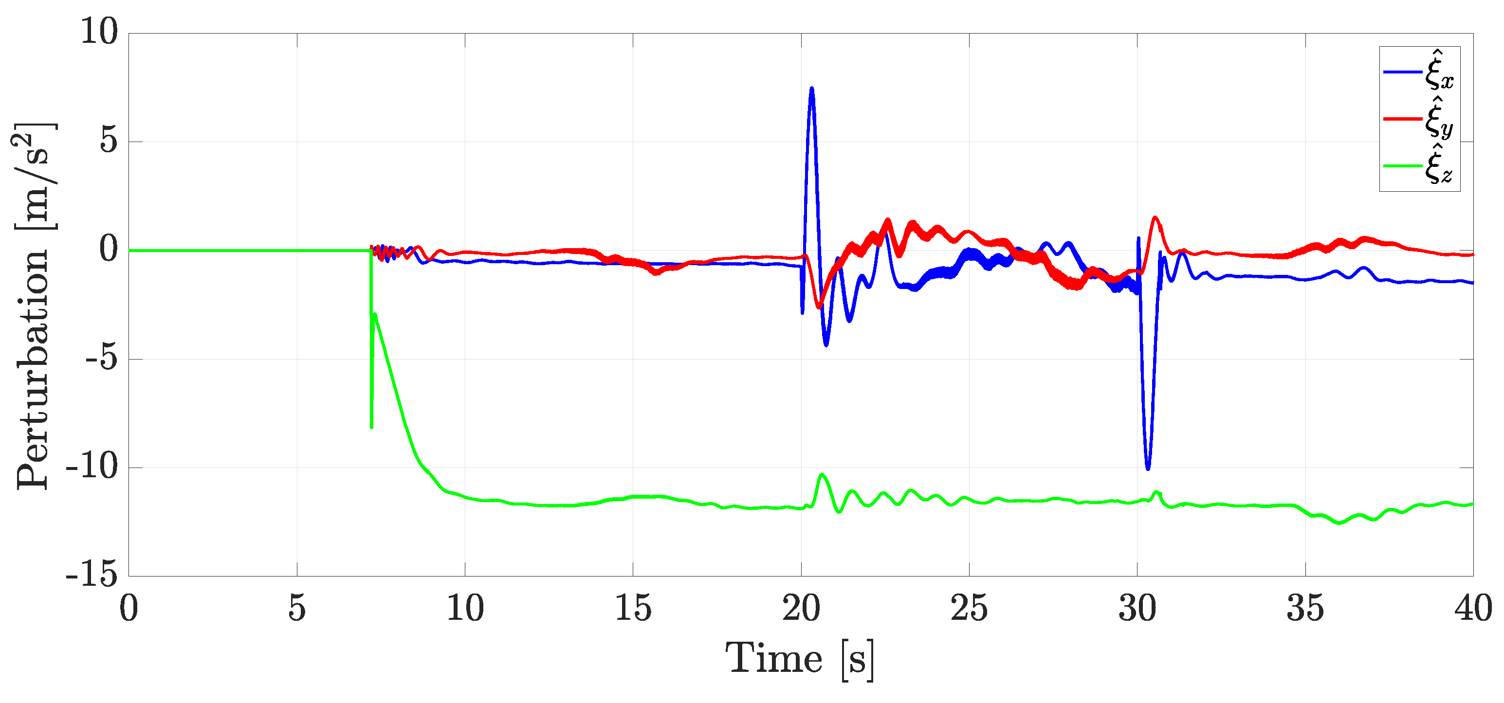
The internal online disturbance estimation is depicted in Figure 12, where it can be noticed that the internal estimated disturbance ξ ^ z had a magnitude closer to the gravity term g. Furthermore, unmodeled dynamics are also lumped in this estimation.

4.4. Experiment with Wind Applied as an External Disturbance

A second experiment with external disturbance was proposed, using the wind produced by a fan in the direction of the X axis and located at 2.5 0 1 m. Table 1 presents fan’s velocity concerning the distance in the X direction.
Figure 13 depicts the quadrotor’s motion, which achieved the trajectory tracking. Note that when the quadrotor was closest to the fan, it was subject to a more significant external disturbance, causing it to momentarily not follow the desired trajectory. However, the control could return the system to the desired trajectory through the disturbance estimation.
Figure 14 shows that the position and orientation errors were close to zero, even in the presence of external perturbations.
Figure 15 shows the estimation of internal and external online disturbances. When comparing Figure 12 with Figure 15, one can notice that the estimated disturbances had a similar structure but different magnitudes.
A video of the experimental results can be watched at https://www.dropbox.com/scl/fi/b4dqnlwryrxhb1l8erfwz/Experiment.mp4?rlkey=c3x903t2gzyrz89fa49ekg9la&st=584hz96g&dl=0 (accessed on 2 September 2024).

5. Discussion

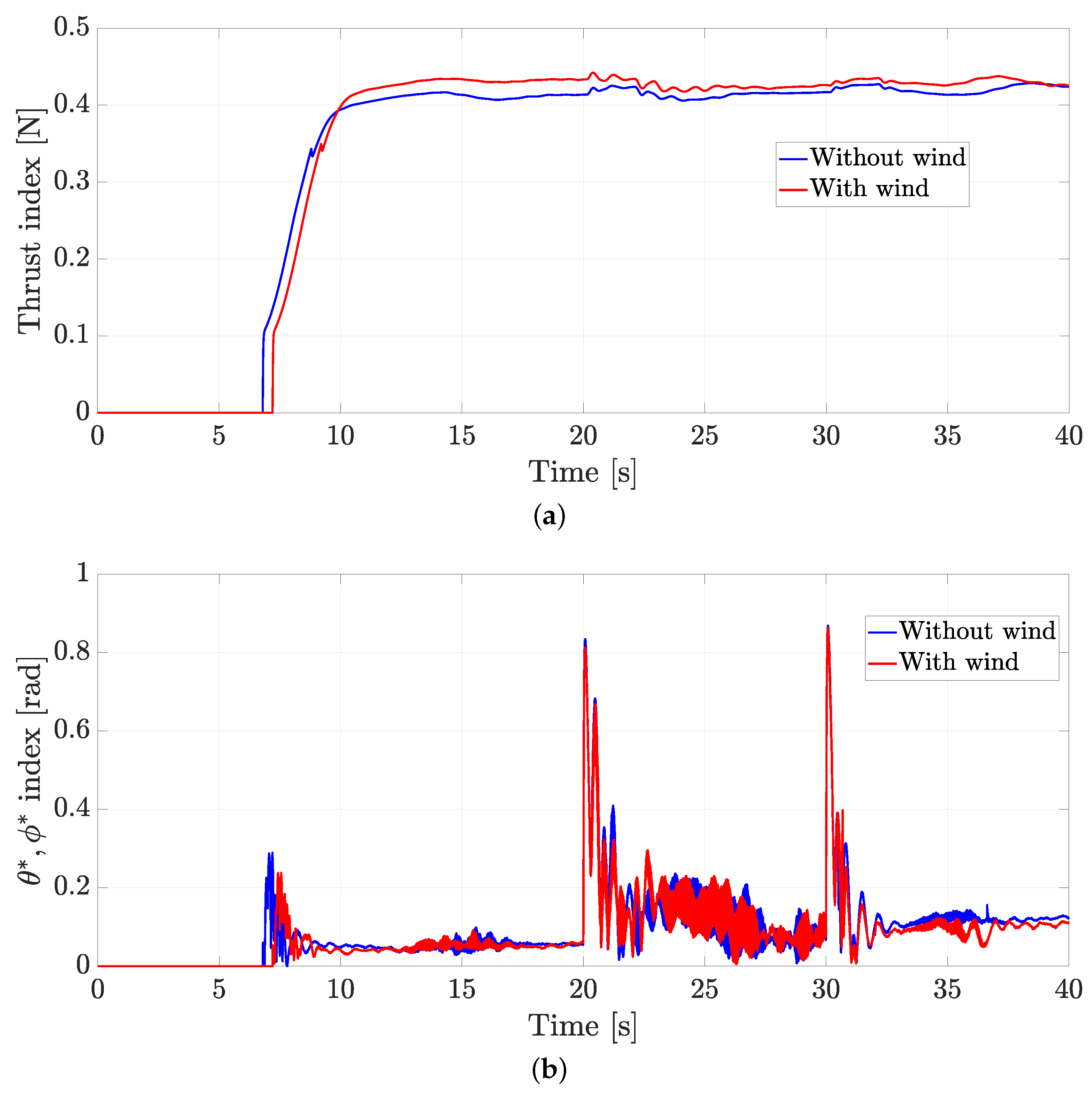
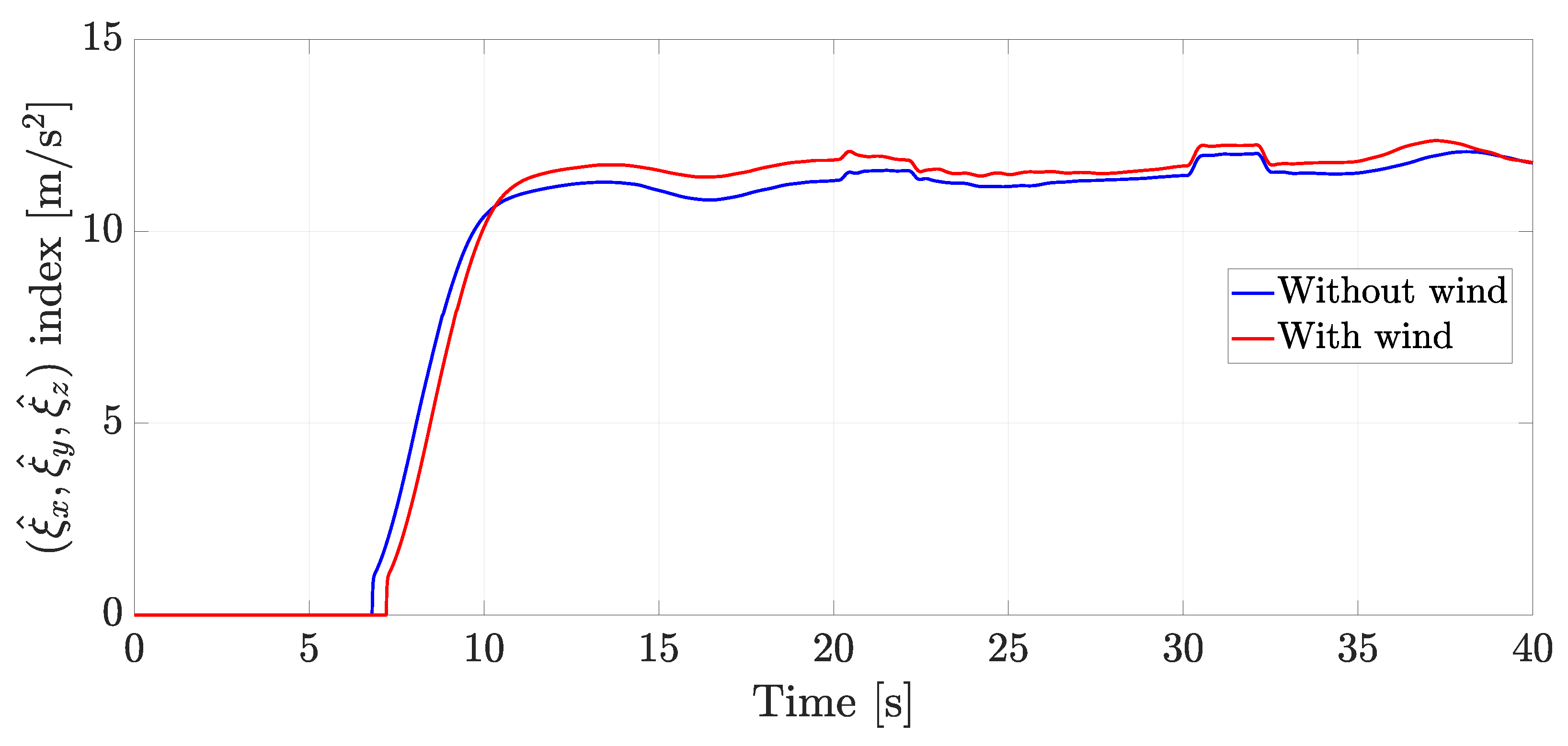
The same average RMS equations given in (33) were used to compare the control’s performance when internal and external perturbations were present, to assess the overall performance.
As Figure 16a shows, more energy was needed when external disturbances affected the motion of the quadrotor. At the same time, in Figure 16b, one can conclude that the desired angles θ * and ϕ * had a similar behavior. Therefore, the proposed ADRC could deal with both internal and external disturbances.
On the other hand, Figure 17 illustrates the average RMS online disturbance estimation index. Note that these disturbances had the same structure; however, when the quadrotor approached the fan, the disturbances increased their amplitude. Based on those mentioned earlier, one can conclude that, even though the estimated perturbations were different, the control strategy could deal with them.

6. Conclusions

This work contributes to the design of a control strategy based on the ADRC approach to control the trajectory tracking of a quadrotor. To achieve this purpose, it was assumed that the internal loop, given by the orientation control, indirectly controls the position (outer loop). Because a GPIO was implemented, which allowed system disturbances to be estimated, the control law only depended on the drone pose measurements. The experimental results allowed us to validate the proposed control scheme. Furthermore, the controller’s performance was tested by estimating internal and external disturbances, where it was evident that it could deal with this type of perturbation.
Further investigations could be related to the problem of multi-agent systems involving robust trajectory tracking, formation, communication delays, and fault estimation diagnosis.

Author Contributions

Conceptualization, M.R.-N., A.L.-J. and J.G.-S.; Data curation, M.R.-N., R.R.-J. and J.A.; Formal analysis, M.R.-N., A.L.-J. and J.G.-S.; Funding acquisition, M.R.-N. and J.G.-S.; Investigation, M.R.-N. and R.R.-J.; Methodology, M.R.-N., A.L.-J. and J.G.-S.; Project administration, M.R.-N. and A.L.-J.; Resources, M.R.-N., J.G.-S. and E.G.H.-M.; Software, M.R.-N., R.R.-J. and J.A.; Supervision, M.R.-N. and A.L.-J.; Validation, R.R.-J. and E.G.H.-M.; Visualization, A.L.-J., J.G.-S. and J.A.; Writing—original draft, M.R.-N. and J.G.-S.; Writing—review and editing, A.L.-J., J.G.-S. and E.G.H.-M. All authors have read and agreed to the published version of the manuscript.

Funding

This work was supported by Universidad Iberoamericana Ciudad de México through the research funds DINVP-025 and by Instituto Politécnico Nacional—Secretaría de Investigación y Posgrado under grants 20240014, and 20240693. The APC was funded by Instituto Politécnico Nacional through Project SIP: 20240014.

Data Availability Statement

Data are contained within the article.

Conflicts of Interest

The authors declare no conflicts of interest.

Abbreviations

The following abbreviations are used in this manuscript:
UAVUnmanned Aerial Vehicles
ADRCActive Disturbance Rejection Control
PIDProportional-Integral-Differential
GPIOGeneralized Proportional Integral Observer
SMCSliding Mode Control
ESOExtended State Observer
CTContinuous Twisting

References

  1. Erdelj, M.; Król, M.; Natalizio, E. Wireless Sensor Networks and Multi-UAV systems for natural disaster management. Comput. Netw. 2017, 124, 72–86. [Google Scholar] [CrossRef]
  2. Khalil, R.A.; Saeed, N.; Almutiry, M. UAVs-assisted passive source localization using robust TDOA ranging for search and rescue. ICT Express 2023, 9, 677–682. [Google Scholar] [CrossRef]
  3. Kedys, J.; Tchappi, I.; Najjar, A. UAVs for Disaster Management—An Exploratory Review. Procedia Comput. Sci. 2024, 231, 129–136. [Google Scholar] [CrossRef]
  4. Alsamhi, S.H.; Ma, O.; Ansari, M.S.; Almalki, F.A. Survey on Collaborative Smart Drones and Internet of Things for Improving Smartness of Smart Cities. IEEE Access 2019, 7, 128125–128152. [Google Scholar] [CrossRef]
  5. Lytridis, C.; Kaburlasos, V.G.; Pachidis, T.; Manios, M.; Vrochidou, E.; Kalampokas, T.; Chatzistamatis, S. An Overview of Cooperative Robotics in Agriculture. Agronomy 2021, 11, 1818. [Google Scholar] [CrossRef]
  6. Shelare, S.; Aglawe, K.; Waghmare, S.; Belkhode, P. Advances in water sample collections with a drone—A review. Mater. Today Proc. 2021, 47, 4490–4494. [Google Scholar] [CrossRef]
  7. Esposito, M.; Crimaldi, M.; Cirillo, V.; Sarghini, F.; Maggio, A. Drone and sensor technology for sustainable weed management: A review. Chem. Biol. Technol. Agric. 2021, 8, 18. [Google Scholar] [CrossRef]
  8. Kumar, A.; Sharma, K.; Singh, H.; Naugriya, S.; Gill, S.; Buyya, R. A drone-based networked system and methods for combating coronavirus disease (COVID-19) pandemic. Future Gener. Comput. Syst. 2021, 115, 1–19. [Google Scholar] [CrossRef]
  9. Nwaogu, J.M.; Yang, Y.; Chan, A.P.; Chi, H.l. Application of drones in the architecture, engineering, and construction (AEC) industry. Autom. Constr. 2023, 150, 104827. [Google Scholar] [CrossRef]
  10. Rojo-García, J.I.; Vera-Chavarría, S.A.; Lozano-Hernández, Y.; Sánchez-Meza, V.G.; González-Sierra, J.; Oliva-Moreno, L.N. Data Collection in Areas without Infrastructure Using LoRa Technology and a Quadrotor. Future Internet 2024, 16, 186. [Google Scholar] [CrossRef]
  11. Nascimento, T.P.; Saska, M. Position and attitude control of multi-rotor aerial vehicles: A survey. Annu. Rev. Control 2019, 48, 129–146. [Google Scholar] [CrossRef]
  12. Li, J.; Li, Y. Dynamic analysis and PID control for a quadrotor. In Proceedings of the 2011 IEEE International Conference on Mechatronics and Automation, Beijing, China, 7–10 August 2011; pp. 573–578. [Google Scholar] [CrossRef]
  13. Salih, A.; Moghavvemi, M.; Mohamed, H.; Gaeid, K. Modelling and PID controller design for a quadrotor unmanned air vehicle. In Proceedings of the International Conference on Automation, Quality and Testing, Robotics, Cluj-Napoca, Romania, 28–30 May 2010; Volume 1, pp. 1–5. [Google Scholar] [CrossRef]
  14. Carrillo, L.R.G.; López, A.E.D.; Lozano, R.; Pégard, C. Quad Rotorcraft Control: Vision-Based Hovering and Navigation; Springer Science & Business Media: Berlin/Heidelberg, Germany, 2012. [Google Scholar]
  15. Castillo, P.; Lozano, R.; Dzul, A. Stabilization of a mini rotorcraft with four rotors. IEEE Control Syst. Mag. 2005, 25, 45–55. [Google Scholar] [CrossRef]
  16. Ríos, H.; González-Sierra, J.; Dzul, A. Robust tracking output-control for a quad-rotor: A continuous sliding-mode approach. J. Frankl. Inst. 2017, 354, 6672–6691. [Google Scholar] [CrossRef]
  17. Nadda, S.; Swarup, A. On adaptive sliding mode control for improved quadrotor tracking. J. Vib. Control 2018, 24, 3219–3230. [Google Scholar] [CrossRef]
  18. Miranda-Moya, A.; Castañeda, H.; Wang, H. Fixed-Time Extended Observer-Based Adaptive Sliding Mode Control for a Quadrotor UAV under Severe Turbulent Wind. Drones 2023, 7, 700. [Google Scholar] [CrossRef]
  19. Shao, X.; Sun, G.; Yao, W.; Liu, J.; Wu, L. Adaptive Sliding Mode Control for Quadrotor UAVs with Input Saturation. IEEE/ASME Trans. Mechatron. 2022, 27, 1498–1509. [Google Scholar] [CrossRef]
  20. Baek, J.; Kang, M. A Synthesized Sliding-Mode Control for Attitude Trajectory Tracking of Quadrotor UAV Systems. IEEE/ASME Trans. Mechatron. 2023, 28, 2189–2199. [Google Scholar] [CrossRef]
  21. Kang, T.; Yoon, K.; Ha, T.; Lee, G. H-infinity Control System Design for a Quad-rotor. J. Inst. Control. Robot. Syst. 2015, 21, 14–20. [Google Scholar] [CrossRef]
  22. Ortiz, J.P.; Minchala, L.I.; Reinoso, M.J. Nonlinear Robust H-Infinity PID Controller for the Multivariable System Quadrotor. IEEE Lat. Am. Trans. 2016, 14, 1176–1183. [Google Scholar] [CrossRef]
  23. Labbadi, M.; Cherkaoui, M. Robust adaptive backstepping fast terminal sliding mode controller for uncertain quadrotor UAV. Aerosp. Sci. Technol. 2019, 93, 105306. [Google Scholar] [CrossRef]
  24. Almakhles, D.J. Robust Backstepping Sliding Mode Control for a Quadrotor Trajectory Tracking Application. IEEE Access 2020, 8, 5515–5525. [Google Scholar] [CrossRef]
  25. Tsai, S.H.; Chang, Y.P.; Lin, H.Y.; Chang, L.M. Design and Implementation of Integral Backstepping Sliding Mode Control for Quadrotor Trajectory Tracking. Processes 2021, 9, 1951. [Google Scholar] [CrossRef]
  26. Zhao, B.; Tang, Y.; Wu, C.; Du, W. Vision-Based Tracking Control of Quadrotor with Backstepping Sliding Mode Control. IEEE Access 2018, 6, 72439–72448. [Google Scholar] [CrossRef]
  27. Roy, R.; Islam, M.; Sadman, N.; Mahmud, M.A.P.; Gupta, K.D.; Ahsan, M.M. A Review on Comparative Remarks, Performance Evaluation and Improvement Strategies of Quadrotor Controllers. Technologies 2021, 9, 37. [Google Scholar] [CrossRef]
  28. Han, J. From PID to active disturbance rejection control. IEEE Trans. Ind. Electron. 2009, 56, 900–906. [Google Scholar] [CrossRef]
  29. Sira-Ramirez, H.; Luviano-Juárez, A.; Ramírez-Neria, M.; Zurita-Bustamante, E.W. Active Disturbance Rejection Control of Dynamic Systems: A Flatness Based Approach; Butterworth-Heinemann: Oxford, UK, 2017. [Google Scholar] [CrossRef]
  30. Borja-Jaimes, V.; Coronel-Escamilla, A.; Escobar-Jiménez, R.F.; Adam-Medina, M.; Guerrero-Ramírez, G.V.; Sánchez-Coronado, E.M.; García-Morales, J. Fractional-Order Sliding Mode Observer for Actuator Fault Estimation in a Quadrotor UAV. Mathematics 2024, 12, 1247. [Google Scholar] [CrossRef]
  31. Nian, X.; Chen, W.; Chu, X.; Xu, Z. Robust adaptive fault estimation and fault tolerant control for quadrotor attitude systems. Int. J. Control 2020, 93, 725–737. [Google Scholar] [CrossRef]
  32. Gao, B.; Liu, Y.J.; Liu, L. Adaptive neural fault-tolerant control of a quadrotor UAV via fast terminal sliding mode. Aerosp. Sci. Technol. 2022, 129, 107818. [Google Scholar] [CrossRef]
  33. Xu, L.; Qin, K.; Tang, F.; Shi, M.; Lin, B. A Novel Attitude Control Strategy for a Quadrotor Drone with Actuator Dynamics Based on a High-Order Sliding Mode Disturbance Observer. Drones 2024, 8, 131. [Google Scholar] [CrossRef]
  34. Dhadekar, D.; Sanghani, P.; Mangrulkar, K.; Talole, S. Robust Control of Quadrotor using Uncertainty and Disturbance Estimation. J. Intell. Robot. Syst. 2021, 101, 60. [Google Scholar] [CrossRef]
  35. Huang, Y.; Liu, W.; Li, B.; Yang, Y.; Xiao, B. Finite-time formation tracking control with collision avoidance for quadrotor UAVs. J. Frankl. Inst. 2020, 357, 4034–4058. [Google Scholar] [CrossRef]
  36. González-Sierra, J.; Dzul, A.; Ríos, H. Robust sliding-mode formation control and collision avoidance via repulsive vector fields for a group of Quad-Rotors. Int. J. Syst. Sci. 2019, 50, 1483–1500. [Google Scholar] [CrossRef]
  37. Xu, L.X.; Ma, H.J.; Guo, D.; Xie, A.H.; Song, D.L. Backstepping Sliding-Mode and Cascade Active Disturbance Rejection Control for a Quadrotor UAV. IEEE/ASME Trans. Mechatron. 2020, 25, 2743–2753. [Google Scholar] [CrossRef]
  38. Xiyang, W.; Mingqiu, L.; Yang, Y.; Hongtao, D. Quadrotor Flight Control Based on Improved Active Disturbance Rejection Control Technology. J. Phys. Conf. Ser. 2021, 1948, 012095. [Google Scholar] [CrossRef]
  39. AlAli, A.; Fareh, R.; Sinan, S.; Bettayeb, M. Control of Quadcopter Drone Based on Fractional Active Disturbances Rejection Control. In Proceedings of the 2021 14th International Conference on Developments in eSystems Engineering (DeSE), Sharjah, United Arab Emirates, 7–10 December 2021; pp. 180–185. [Google Scholar] [CrossRef]
  40. Orozco Soto, S.M.; Cacace, J.; Ruggiero, F.; Lippiello, V. Active Disturbance Rejection Control for the Robust Flight of a Passively Tilted Hexarotor. Drones 2022, 6, 258. [Google Scholar] [CrossRef]
  41. Wang, Z.; Huang, D.; Huang, T.; Qin, N. Active disturbance rejection control for a quadrotor UAV. In Proceedings of the 2020 IEEE 9th Data Driven Control and Learning Systems Conference (DDCLS), Liuzhou, China, 19–21 June 2020; pp. 1–5. [Google Scholar] [CrossRef]
  42. Suhail, S.A.; Bazaz, M.A.; Hussain, S. Adaptive sliding mode-based active disturbance rejection control for a quadcopter. Trans. Inst. Meas. Control 2022, 44, 3176–3190. [Google Scholar] [CrossRef]
  43. Chang, K.; Xia, Y.; Huang, K.; Ma, D. Obstacle avoidance and active disturbance rejection control for a quadrotor. Neurocomputing 2016, 190, 60–69. [Google Scholar] [CrossRef]
  44. Dong, W.; Gu, G.Y.; Zhu, X.; Ding, H. A high-performance flight control approach for quadrotors using a modified active disturbance rejection technique. Robot. Auton. Syst. 2016, 83, 177–187. [Google Scholar] [CrossRef]
  45. Díaz-Téllez, J.; Guerrero-Castellanos, J.F.; Pouthier, F.; Marchand, N.; Durand, S. In-Ground-Effect Disturbance-Rejection Altitude Control for Multi-Rotor UAVs. J. Intell. Robot. Syst. 2023, 109, 1–18. [Google Scholar] [CrossRef]
  46. Fliess, M.; Lévine, J.; Martin, P.; Rouchon, P. Flatness and defect of non-linear systems: Introductory theory and examples. Int. J. Control 1995, 61, 1327–1361. [Google Scholar] [CrossRef]
  47. Sira-Ramirez, H.; Agrawal, S.K. Differentially Flat Systems; CRC Press: Boca Raton, FL, USA, 2004. [Google Scholar]
  48. Aguilar-Ibáñez, C.; Sira-Ramírez, H.; Suárez-Castañón, M.S.; Martínez-Navarro, E.; Moreno-Armendariz, M.A. The trajectory tracking problem for an unmanned four-rotor system: Flatness-Based approach. Int. J. Control 2012, 85, 69–77. [Google Scholar] [CrossRef]
  49. Martinez-Vasquez, A.H.; Castro-Linares, R.; Rodríguez-Mata, A.E.; Sira-Ramírez, H. Spherical Inverted Pendulum on a Quadrotor UAV: A Flatness and Discontinuous Extended State Observer Approach. Machines 2023, 11, 578. [Google Scholar] [CrossRef]
  50. Castillo, P.; Lozano, R.; Dzul, A.E. Modelling and Control of Mini-Flying Machines; Springer Science & Business Media: Berlin/Heidelberg, Germany, 2005. [Google Scholar]
  51. Sira-Ramírez, H.; Ramírez-Neria, M.; Rodríguez-Angeles, A. On the linear control of nonlinear mechanical systems. In Proceedings of the 49th IEEE Conference on Decision and Control (CDC), Atlanta, GA, USA, 15–17 December 2010; pp. 1999–2004. [Google Scholar]
  52. Lopez-Sanchez, I.; Moreno-Valenzuela, J. PID control of quadrotor UAVs: A survey. Annu. Rev. Control 2023, 56, 100900. [Google Scholar] [CrossRef]
  53. Fliess, M.; Join, C. Model-free control. Int. J. Control 2013, 86, 2228–2252. [Google Scholar] [CrossRef]
  54. Huba, M.; Gao, Z. Uncovering disturbance observer and ultra-local plant models in series PI controllers. Symmetry 2022, 14, 640. [Google Scholar] [CrossRef]
  55. Ramírez-Neria, M.; Morales-Valdez, J.; Yu, W. Active vibration control of building structure using active disturbance rejection control. J. Vib. Control 2022, 28, 2171–2186. [Google Scholar] [CrossRef]
  56. Gao, Z. Scaling and bandwidth-parameterization based controller tuning. Proc. Am. Control Conf. 2003, 6, 4989–4996. [Google Scholar] [CrossRef]
  57. Kim, Y.; Keel, L.; Bhattacharyya, S. Transient response control via characteristic ratio assignment. IEEE Trans. Autom. Control 2003, 48, 2238–2244. [Google Scholar] [CrossRef]
  58. Wu, Z.H.; Zhou, H.C.; Guo, B.Z.; Deng, F. Review and new theoretical perspectives on active disturbance rejection control for uncertain finite-dimensional and infinite-dimensional systems. Nonlinear Dyn. 2020, 101, 935–959. [Google Scholar] [CrossRef]
  59. Qi, S.; Zhe, J. UKF based two-timescale control for a helicopter. In Proceedings of the 2016 14th International Conference on Control, Automation, Robotics and Vision (ICARCV), Phuket, Thailand, 13–15 November 2016; IEEE: New York, NY, USA, 2016; pp. 1–5. [Google Scholar] [CrossRef]
  60. González-Sierra, J.; Ríos, H.; Dzul, A. Quad-Rotor robust time-varying formation control: A Continuous Sliding-Mode Control approach. Int. J. Control 2020, 93, 1659–1676. [Google Scholar] [CrossRef]
  61. L’Afflitto, A. Control Multiple AR.Drone 2.0 with Vicon Feedback. MATLAB Central File Exchange. 2022. Available online: https://www.mathworks.com/matlabcentral/fileexchange/63026-control-multiple-ar-drone-2-0-with-vicon-feedback (accessed on 2 September 2024.).
Figure 1. Quadrotor UAV force diagram. The forces f 1 , f 2 , f 3 , and f 4 are the thrust of each motor with the following relation F = = 1 4 f , and f = k ω 2 where k is the thrust constant and ω is the angular velocity.
Actuators 13 00340 g001
Figure 2. Quadrotor trajectory comparison.
Actuators 13 00340 g002
Figure 3. Control input comparison. (a) Thrust. (b) Torques.
Actuators 13 00340 g003
Figure 4. Position tracking error comparison.
Actuators 13 00340 g004
Figure 5. Orientation angle comparison.
Actuators 13 00340 g005
Figure 6. RMS control input comparison. (a) RMS Thrust. (b) RMS Torques.
Actuators 13 00340 g006
Figure 7. RMS error comparison. (a) RMS position error. (b) RMS orientation error.
Actuators 13 00340 g007
Figure 8. Experimental quadrotor.
Actuators 13 00340 g008
Figure 9. Experimental platform scheme.
Actuators 13 00340 g009
Figure 10. Trajectory tracking performance of the quadrotor. (a) Trajectory tracking of the quadrotor in a 3 dimensional space with internal disturbances. (b) Trajectory tracking in the Z coordinate.
Actuators 13 00340 g010
Figure 11. Position and orientation errors with internal disturbances. (a) Position errors. (b) Orientation errors.
Actuators 13 00340 g011
Figure 12. Internal online disturbance estimation.
Actuators 13 00340 g012
Figure 13. Trajectory tracking performance of the quadrotor with external disturbance. (a) Trajectory tracking of the quadrotor in a 3 dimensional space. (b) Trajectory tracking in the Z coordinate.
Actuators 13 00340 g013
Figure 14. Position and orientation errors with external disturbance. (a) Position errors. (b) Orientation errors.
Actuators 13 00340 g014
Figure 15. Internal and external online disturbance estimation.
Actuators 13 00340 g015
Figure 16. Comparison of quadratic control inputs. (a) Quadratic thrust index. (b) Quadratic auxiliary control index.
Actuators 13 00340 g016
Figure 17. Comparison of the quadratic online disturbance estimation index.
Actuators 13 00340 g017
Table 1. The fan’s velocity concerning the distance to the fan.
Distance [m]Velocity [m/s]
1 4.2
1.5 2.9
2.5 2.6
3.5 1.9
5 1.4
Disclaimer/Publisher’s Note: The statements, opinions and data contained in all publications are solely those of the individual author(s) and contributor(s) and not of MDPI and/or the editor(s). MDPI and/or the editor(s) disclaim responsibility for any injury to people or property resulting from any ideas, methods, instructions or products referred to in the content.