1. Introduction
Maglev trains, as a typical representative of new rail transit technologies, primarily rely on a suspension system that actively controls the generation of time-varying electromagnetic forces, allowing the train to stably levitate above the track. Compared to traditional wheeled trains, maglev trains present several advantages, including the absence of mechanical contact wear, high operational speeds, strong adaptability to varied terrains, and environmental friendliness. However, maglev trains are classified as open-loop unstable systems, characterized by significant nonlinear properties and susceptibility to external disturbances, making control challenging [
1,
2]. Nonetheless, as a mode of transportation, the commercial operation of maglev trains demands stringent safety standards throughout the operational process. This necessitates that the control performance of the controller remains at a high level, requiring robust handling of external disturbances and system uncertainties. Therefore, research on control algorithms for maglev trains is of paramount importance.
Active Disturbance Rejection Controller (ADRC) was originally proposed by Han [
3]. Due to its features of fast response, low overshoot, and strong disturbance rejection capability, it has been widely applied in engineering practice [
4,
5,
6,
7]. The fundamental idea of ADRC is to use an Extended State Observer (ESO) to uniformly observe and compensate for system uncertainties and external disturbances. The strong disturbance rejection and good robustness of ADRC make it suitable for the control of maglev trains. However, maglev trains exhibit non-minimum phase (NMP) characteristics, the internal loop of the system is unstable because it has positive roots. And there is no definitive correspondence between the system’s amplitude-frequency characteristics and phase-frequency characteristics. For minimum phase systems, a larger bandwidth of the ESO is beneficial for the stability and dynamic performance of the system; this situation is not applicable to the control of non-minimum phase systems, which makes it challenging for traditional ADRC structures to achieve a balance between system stability and control performance. Zhao [
8] has proven that the standard ADRC controller based on the relative order design for non-minimum phase systems is likely to be unstable. A common approach to applying ADRC to non-minimum phase systems is to take model information into account by constructing a state space model of the system and utilizing it into the design of the ESO. Xue [
9] have studied the selection of the standard form and stability conditions for NMP disturbance rejection systems. Sun [
10] designed a control structure that combines feedforward control with an improved ADRC specifically for non-minimum phase systems, replacing the conventional series integral standard form with a known nominal model and designing an improved ESO based on this, so that the uncertain object’s characteristics in the low-frequency range approach those of the nominal model. Liu [
11] obtained explicit expressions for internal disturbances through the reconstruction of non-minimum phase systems, designing a new ADRC control structure and deriving internal stability criteria for disturbance rejection systems. These studies indicate that the design of the ESO based on model information is effective for ADRC control of NMP systems.
In order to simplify the structure of the ADRC and make parameter tuning easier, Gao [
12] linearized the Extended State Observer and feedback control law, making linear ADRC (LADRC) more suitable for engineering applications. The linear ESO has a simple structure, with a defined relationship between gain and observer bandwidth, facilitating easy parameter tuning; however, the high constant gain may lead to a ‘peaking’ problem in the system [
13]. The nonlinear mechanism has unique advantages in improving the estimation efficiency of the Extended State Observer and achieving high accuracy and disturbance rejection capabilities [
14,
15]. Nevertheless, when the disturbance magnitude is large, the gain becomes very small, resulting in a significant decline in observer performance. Therefore, to enhance observation performance, it is possible to combine the advantages of linear and nonlinear mechanisms to improve the disturbance rejection capability and response speed of ADRC. Xu [
16] proposed a switched Extended State Observer to achieve rapid and high-precision estimation of force, realizing a control strategy without force sensors.
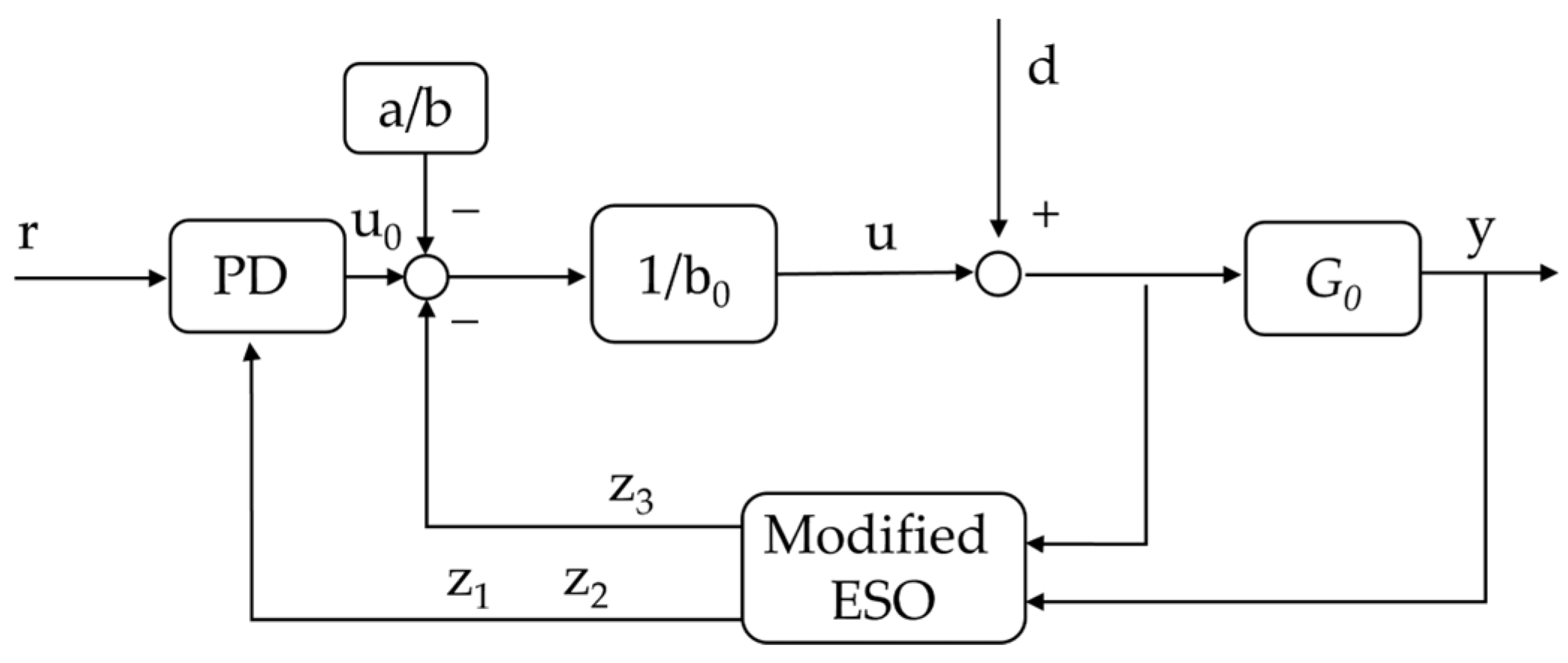
Considering the non-minimum phase characteristics of magnetic levitation trains and unknown external disturbances, a modified ADRC strategy is proposed based on a linear ADRC framework. This strategy integrates model information and nonlinear mechanisms into the design of the Extended State Observer (ESO) to achieve high-performance control for magnetic levitation trains. The main contributions are as follows:
(1) On the basis of the LADRC control framework, the model information of the maglev train is used for the design of the ESO, and the linear feedback control law is changed accordingly for the MESO. On this basis, the stability analysis of the MESO is carried out.
(2) A simulation model of the single-point suspension system is built, and it is verified that the modified ADRC not only makes the recovery process more stable and faster, but also optimizes the steady-state performance. Comparative experiments were carried out on the actual single-point suspension system test bench. The results show that under load disturbance, compared with PID and traditional LADRC, the modified ADRC has better transient recovery process and steady-state performance (smaller adjustment time and lower integral absolute error).
This paper is organized as follows: In
Section 2, the mathematical model of the single-point suspension system for magnetic levitation trains is established, and its non-minimum phase characteristics are analyzed.
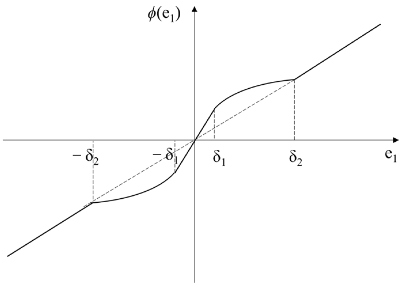
Section 3 presents the structure of the modified ADRC strategy and proposes an modified ESO based on model information for estimating external disturbances. The equivalent gain method is used to convert the linear and nonlinear structures into a unified form, and the stability of the ESO is proven using the Lyapunov criterion. In
Section 4, a simulation model of the single-point suspension system is constructed, and a comparison is made among the transient responses, steady-state characteristics, and disturbance rejection capabilities of the systems under PID, LADRC, and modified ADRC control.
Section 5 validates static levitation and disturbance resistance experiments on the single-point suspension system testbed. Finally,
Section 6 concludes the paper.
4. Simulation Experiments
The operation process of the maglev train encompasses four working conditions: levitation initiation, static suspension, inter-station journey, and train touchdown. The value of the suspension gap typically ranges from 0 to 15 mm. When the train lands, the car body is supported by the track, and there is no control effect at this point. The gap remains at 15 mm. When the train attains steady-state suspension, the gap is 8 mm. During the train operation, the gap fluctuates approximately around 8 mm. It is anticipated that a high-performing controller can stably suspend at the desired gap and fulfill the following requirements: (1) The system possesses a rapid response speed and a minor overshoot; (2) It demonstrates excellent adaptability to the uncertainty and time-varying nature of the parameters in the suspension system; (3) It exhibits a superior ability to suppress external disturbances. To verify the performance superiority of the control algorithm in comparison with the traditional PID and ADRC controllers, a simulation model of the single-point suspension system is constructed based on the system given in Formula (1) for experiments and analysis.
4.1. Design of Controller
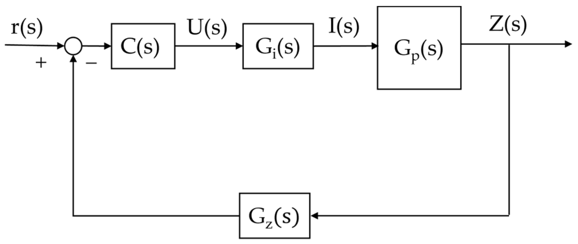
For the design of the general control framework of this controlled object, as depicted in
Figure 4. Herein,
represents the reference input signal,
denotes the control quantity,
stands for the control current, is the output,
refers to the controller,
is the transfer function of the current loop, and
is the transfer function of the displacement sensor.
The bandwidth of the displacement sensor is extremely high and is characterized by the proportional link.
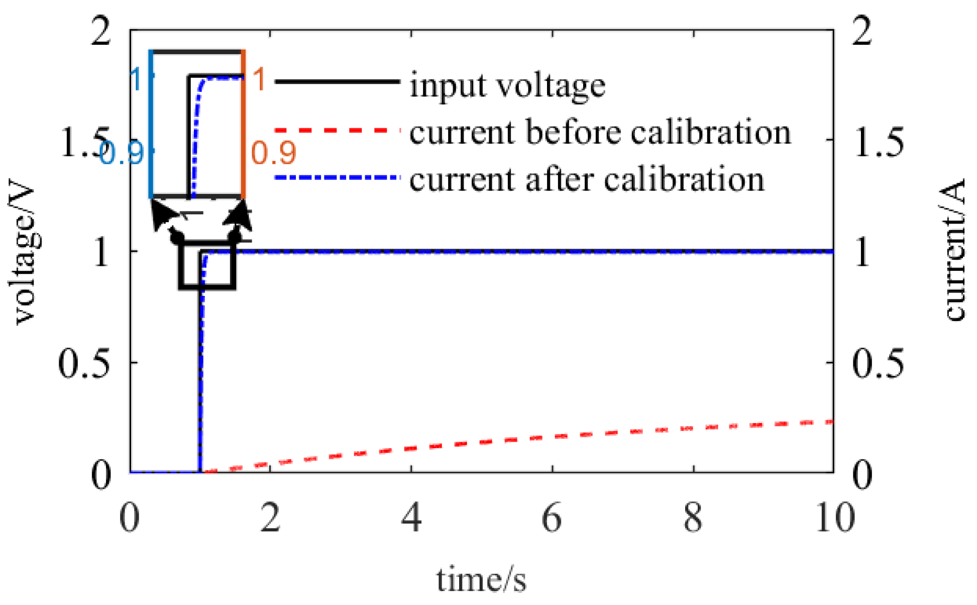
Owing to the hysteresis property of the electromagnet, a time delay exists between the control voltage and the control current. This property will result in an untimely response of the electromagnetic force to the control signal, thereby influencing the control performance and even giving rise to the risk of instability in the control system. The time delay can be eliminated by the design of the current loop, and the structure of the current loop is presented as
After the introduction of the current loop, the time lag between the control current and the control voltage can be eliminated through parameter adjustment, and the current can rapidly track the input voltage, as depicted in
Figure 5. The electromagnet can be approximated as a proportional link with a gain of 1 within the main response frequency band of the system. Hence, the current signal can be approximately regarded as the control quantity.
Three controllers were devised, and their parameters were adjusted for the optimal performance respectively: PID controller {
,
,
}; Regarding the tuning of ADRC, typically, as the bandwidth of the observer rises, the controller’s suppression effect on disturbances improves. Nevertheless, the system is inevitably influenced by noise during actual operation. As the bandwidth increases, the impact of measurement noise will be magnified. Hence, the selection of the observer bandwidth should strike a balance between the disturbance observation ability and the measurement noise suppression ability. According to the bandwidth tuning approach proposed in Literature [
12], the gain coefficient of LESO and the observer bandwidth fulfill the following relationship:
; Choose parameters for LADRC controller as {
,
,
,
}; Choose parameters for MADRC controller as {
,
,
,
,
,
,
}.
4.2. Analysis of Tracking Performance
The initial gap of the single-point suspension system is set at 15 mm, and the anticipated steady-state suspension gap is 8 mm.
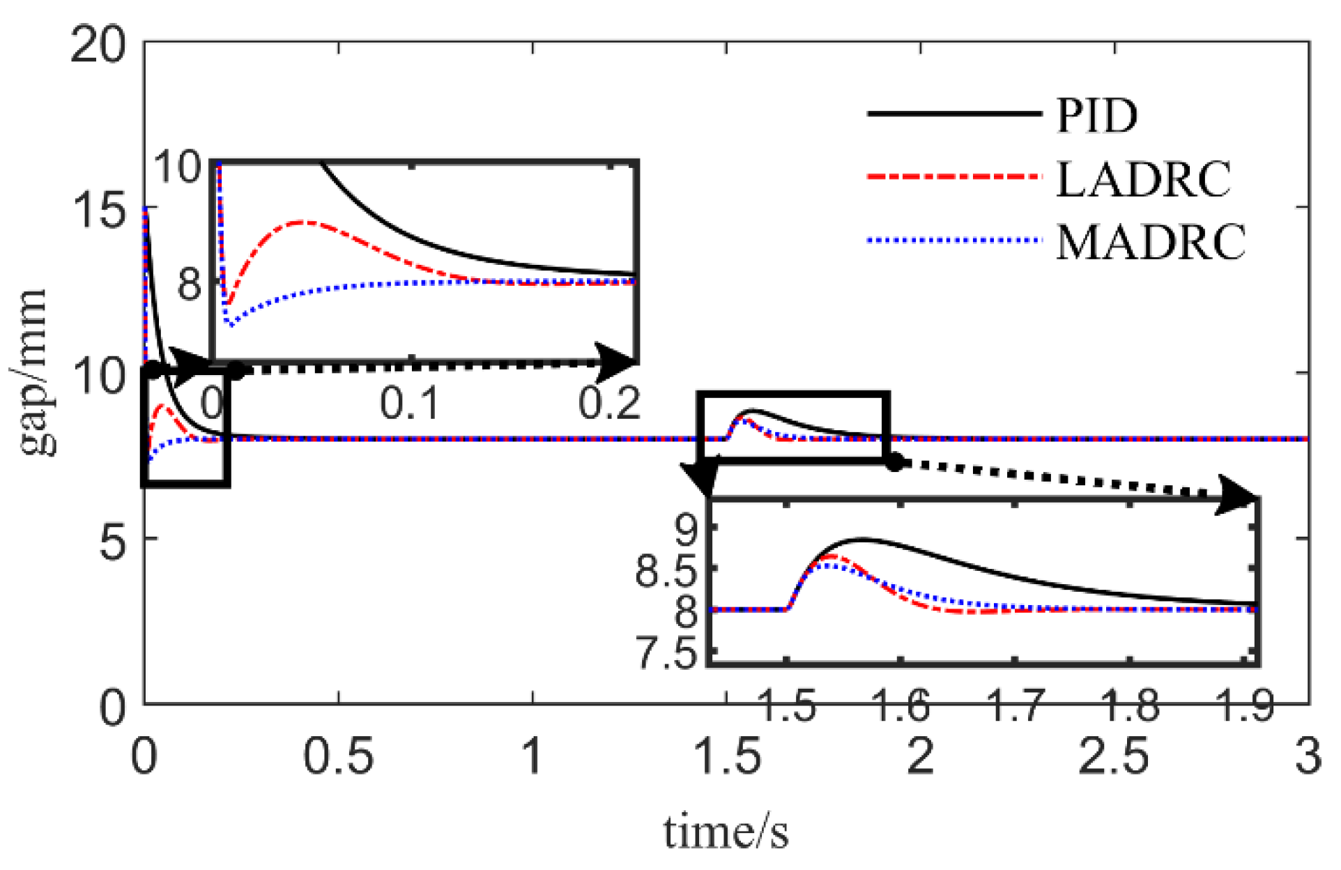
Figure 6 presents the gap response curves under the governance of three controllers. Under the circumstance of well-tuned parameters, it can be observed that:
(1) The system response curve under PID control exhibits no overshoot, yet the adjustment time is considerably longer than those of the two ADRC control strategies;
(2) The system adjustment time under LADRC control is the shortest, but the oscillation is the most pronounced;
(3) The system adjustment time under MADRC control is equivalent to that of the LADRC controller, but the response curve is relatively smooth, and it smoothly transits to the expected gap after a slight overshoot.
Consequently, it can be concluded that the MADRC controller reduces the system adjustment time and renders the system transition process more gentle compared to the LADRC controller.
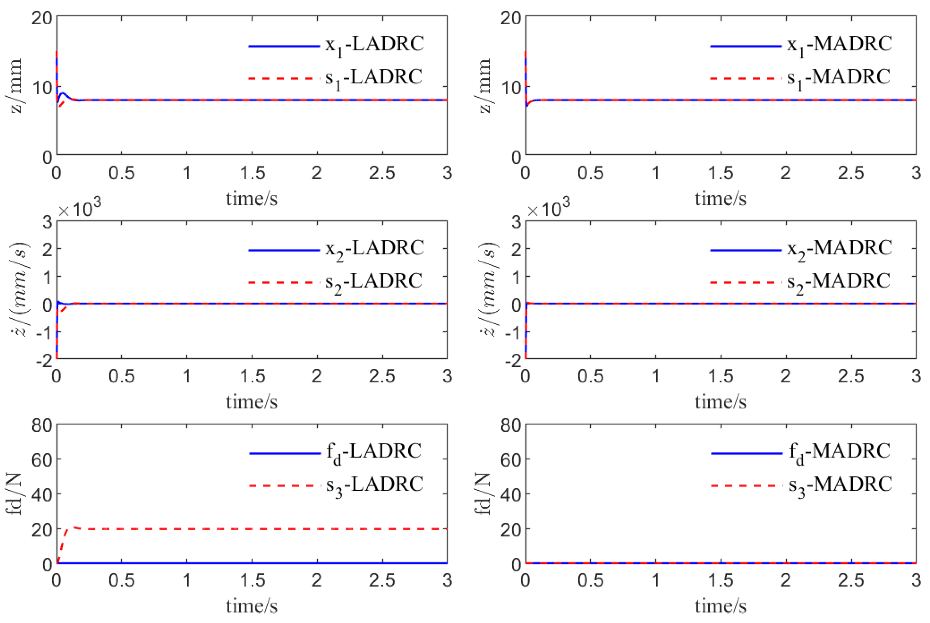
Figure 7 presents the estimation of the system state and disturbance by ESO under two types of ADRC control. In
Figure 7,
,
and
represent system state variables, which are the suspend gap, the derivative of the gap, and the expansion state variable, respectively. Meanwhile,
,
and
represent the ESO’s estimations of the system state variables
,
and
, respectively. The same goes for Figure 9. It is conspicuously evident that MESO possesses a higher-precision and faster estimation capability for the system state
(gap) and
(derivative of the gap). Simultaneously, it can be observed that the ESO which does not utilize the model information will estimate the deviation between the actual model and the standard model as a part of the disturbance, which undoubtedly augments the observation burden of ESO.
4.3. Analysis of Anti-Disturbance Capacity
To validate the suppression capacity of the MADRC control scheme regarding load disturbances, a step disturbance with an amplitude of 10 N was introduced, and the gap variance between the electromagnet and the track is depicted in
Figure 8. By comparing the alterations of the gap fluctuations, the subsequent conclusions can be drawn:
(1) When exposed to load step disturbances of the same magnitude, the peak size relationship of the gap variation is: MADRC < LADRC < PID. This implies that MADRC possesses a more potent anti-interference capability than the LADRC and PID controllers and can handle the impacts brought about by variations in the external environment more effectively.
(2) The adjustment time of MADRC and LADRC is notably superior to that of the PID controller. By comparing the performance of distinct controllers upon perturbation, it can be observed that MADRC has a milder dynamic response compared to LADRC, which further substantiates that MADRC has the most excellent transient response characteristics during the perturbation.
Hence, in a system demanding stable and efficient suppression of perturbation and rapid and precise adjustment time, selecting the MADRC control strategy is a dependable choice.
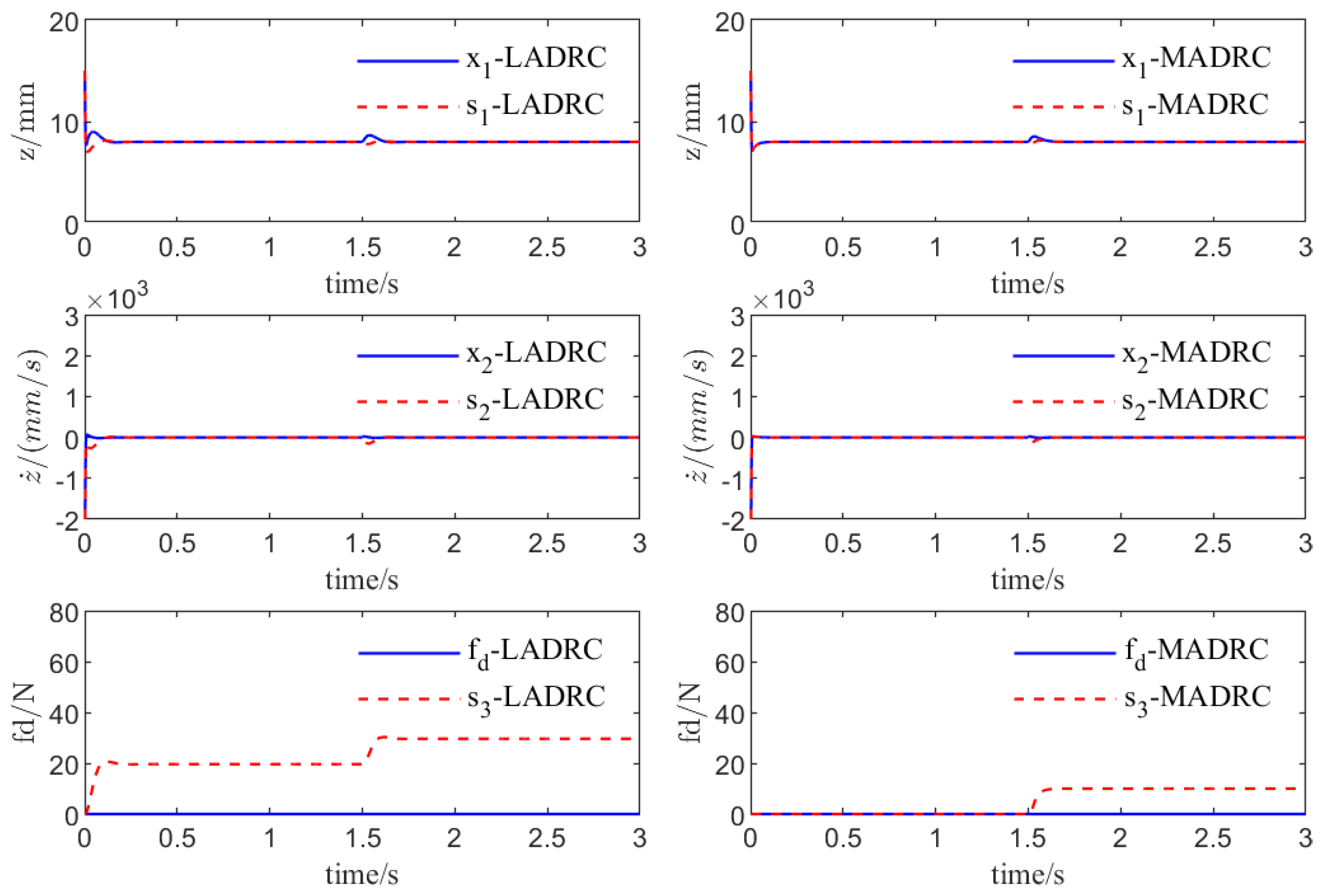
Figure 9 depicts the estimation of the system state and disturbance via the ESO under two types of ADRC control. The MESO possesses a higher-precision and faster estimation capability for the system state and can precisely estimate the external disturbance.
The error integral index employs the integral form of the deviation value between the actual output data and the set output data to represent the performance of the system. The smaller the error integral index is, the better the control performance of the system will be. Commonly utilized ones encompass the Integral of Absolute Error (IAE) and the Integral of Squared Error (ISE). The IAE index has an excellent reflection on the accumulation of small deviations in the system output. The smaller its value is, the better the damping and transient response characteristics of the system will be. The ISE index can reflect the large deviation and response speed of the system output more effectively and is associated with the energy consumption of the system. The smaller its value is, the lower the consumption will be. The error integral indices of the system under different controllers are calculated respectively, as shown in the
Table 1.
5. Experiment
The experimental platform of the single-point suspension system is depicted in the
Figure 10. The framework of the control system encompasses electromagnet, gap sensor, control circuits, and power amplifier circuits. A specific current passing through the winding of the electromagnet will engender electromagnetic force. In the suspension system experiment, the DSP control board is utilized to generate PWM waves as the control signal. After the chopping circuit amplifies the signal, a control voltage is applied across both ends of the electromagnet to generate an actively controllable electromagnetic force, thereby enabling the electromagnetic force to be balanced with the gravity of the load.
It can be derived from Formula (1) that the magnitude of the electromagnetic force exerted between the electromagnet and the track is inversely proportional to the square of the distance separating them. Once the equilibrium state is marginally disrupted, it will result in the landing or adsorption of this node onto the track, and it is unable to suspend stably. Thus, closed-loop control of the system is imperative. The distance variation between the electromagnet and the track is detected by the eddy current sensor. When the electromagnet is disturbed and descends, with the distance expanding, the sensor generates a corresponding change signal. After being modulated by the controller and amplified by the power amplifier, the control current in the control winding of the electromagnet rises correspondingly, the electromagnetic force increases, and the maglev vehicle is drawn back to the equilibrium position.
5.1. Experiment of Suspension
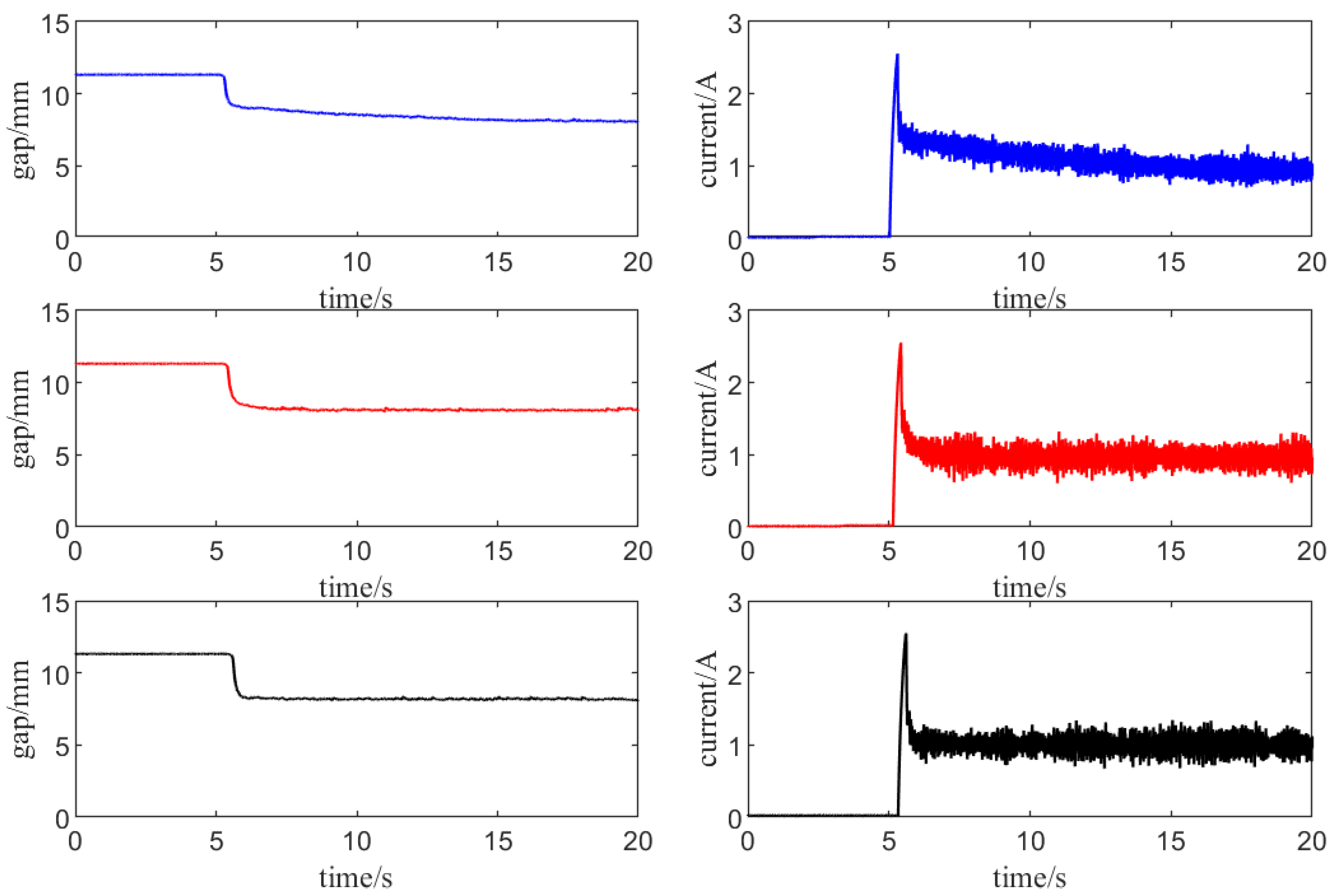
Let the electromagnet float from the static state under the control action to validate the static suspension performance under the enhanced ADRC control. When in a static state, the gap between the electromagnet and the track on the experimental table is 11.314 mm, and the control objective is to enable the electromagnet to stably suspend at a distance of 8 mm from the upper track. The gaps and currents under different controllers during the levitation phase are shown in
Figure 11.
The curves of the identical color are associated with the output response curves (gaps) and control signals (currents) under the identical controller. Among these, the blue curves pertain to the PID controller, the red curves relate to the LADRC controller, and the black curves correspond to the MADRC controller (
Figure 12 is the same as this). Calculate the IAE and ISE indices of the output response curves, the settling time
, the maximum current
, and the current
at the steady state respectively.
According to the results obtained in the
Table 2, the response rate of the ADRC controller is significantly higher than that of the PID controller. For practical engineering applications, this situation indicates that the ADRC controller can adjust to system changes more quickly, thereby enhancing the stability and robustness of the system. In contrast, MADRC shows more excellent performance in transient response characteristics, and its control quantities are also smaller.
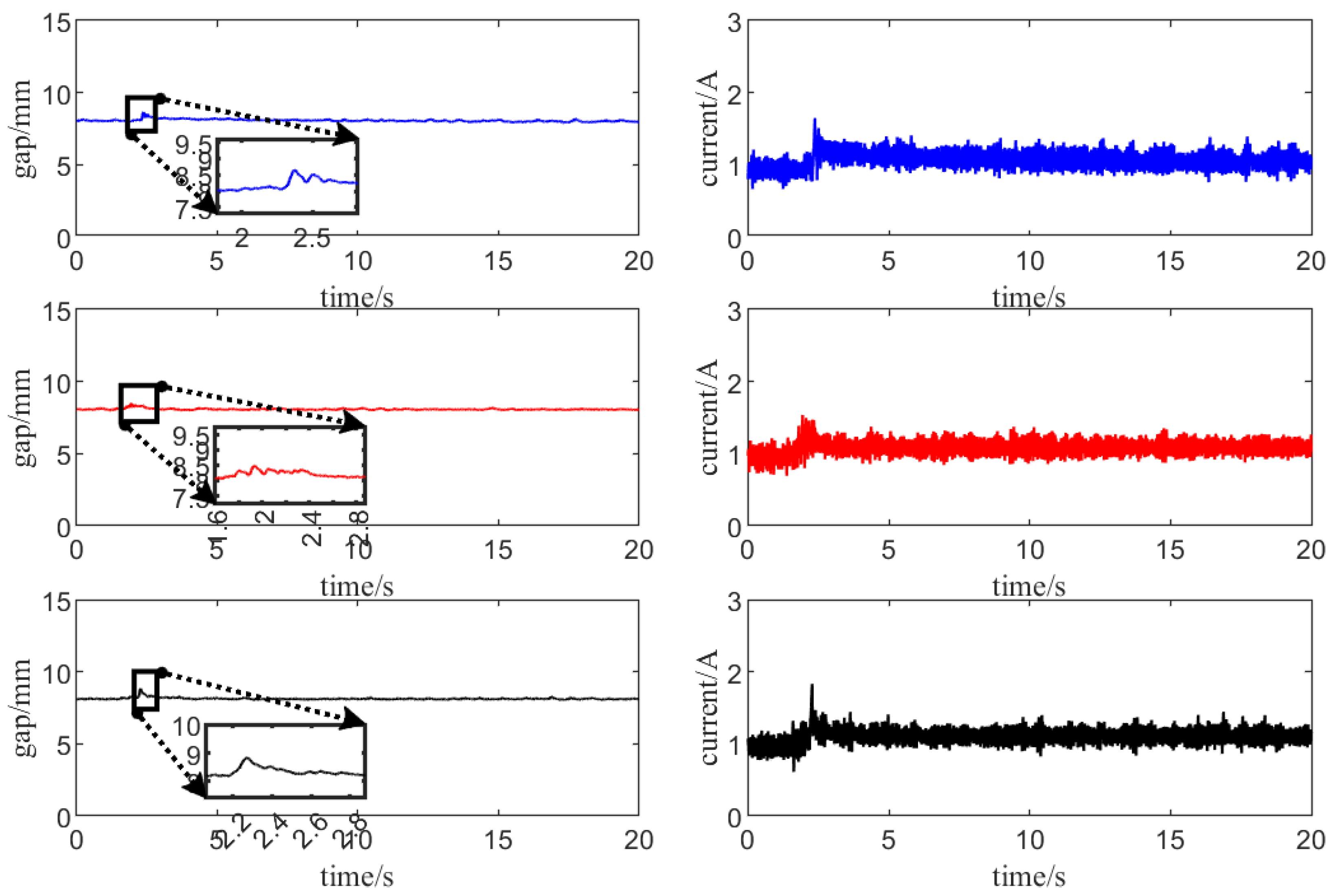
5.2. Experiment of Anti-Disturbance
In the stable suspension state of the electromagnet, a load with a weight of 6.2 kg is added, and the anti-disturbance performance of different controllers is observed and compared. The maximum value of the gap fluctuation , the maximum value of the current , and the adjustment time from being disturbed to returning to the equilibrium state are calculated.
The Modified Active Disturbance Rejection Controller (MADRC) exhibits a significantly superior settling time compared to the Proportional-Integral-Derivative (PID) controller and the Linear Active Disturbance Rejection Controller (LADRC). A comparative analysis of the performance of various controllers during the recovery process reveals that MADRC offers a considerably smoother recovery trajectory in response to disturbances when compared to LADRC. This observation further corroborates that MADRC possesses the most favorable transient response characteristics under disturbance conditions.

