Article

Data-Driven Control Method Based on Koopman Operator for Suspension System of Maglev Train

1
Institute of Rail Transit, Tongji University, Shanghai 201804, China
2
National Maglev Transportation Engineering R&D Center, Tongji University, Shanghai 201804, China
3
State Key Laboratory of High-Speed Maglev Transportation Technology, Tongji University, Shanghai 201804, China
4
Key Laboratory of Maglev Technology in Railway Industry, Tongji University, Shanghai 201804, China
*
Author to whom correspondence should be addressed.
Actuators 2024, 13(10), 397; https://doi.org/10.3390/act13100397
Submission received: 11 September 2024 / Revised: 30 September 2024 / Accepted: 2 October 2024 / Published: 3 October 2024
(This article belongs to the Special Issue Advanced Theory and Application of Magnetic Actuators—2nd Edition)

Abstract

:
The suspension system of the Electromagnetic Suspension (EMS) maglev train is crucial for ensuring safe operation. This article focuses on data-driven modeling and control optimization of the suspension system. By the Extended Dynamic Mode Decomposition (EDMD) method based on the Koopman theory, the state and input data of the suspension system are collected to construct a high-dimensional linearized model of the system without detailed parameters of the system, preserving the nonlinear characteristics. With the data-driven model, the LQR controller and Extended State Observer (ESO) are applied to optimize the suspension control. Compared with baseline feedback methods, the optimization control with data-driven modeling reduces the maximum system fluctuation by 75.0% in total. Furthermore, considering the high-speed operating environment and vertical dynamic response of the maglev train, a rolling-update modeling method is proposed to achieve online modeling optimization of the suspension system. The simulation results show that this method reduces the maximum fluctuation amplitude of the suspension system by 40.0% and the vibration acceleration of the vehicle body by 46.8%, achieving significant optimization of the suspension control.

1. Introduction

The Electromagnetic Suspension (EMS) maglev train relies on the magnetic attraction between the suspension electromagnet and the track to achieve non-contact operation. Due to the open-loop instability inherent in the suspension system, active control methods are essential to maintain stable suspension of the electromagnet. Effective active control of the suspension system requires precision and robustness against disturbances to ensure the train’s stability and safety, as the suspension system is subject to various influences, such as external forces and track irregularities during the operation. To achieve this, several control algorithms have been proposed, including linear model-based control methods incorporating LQR [1] and PID [2], nonlinear control methods such as sliding mode control [3] and backstepping method [4], and intelligent control methods represented by fuzzy control and neural networks [5]. In addition, some researchers focus on constructing observers and filters to enhance the suspension system’s resilience to operational disturbances. For example, Zhu et al. [6] used an Extended State Observer (ESO) to observe and compensate for disturbances in the system, and Wang et al. [7] constructed a Kalman filter to suppress electromagnetic interference in the system.
The analysis and design of the above control methods mostly rely on the system mechanism model. However, during operation, system performance parameters can fluctuate, leading to deviations from theoretical values and introducing uncertainties in the modeling analysis and controller design. For example, the temperature rise and eddy current effect of the electromagnet affect the suspension force [8]. Performance degradation occurs during the operation when the control loop is interfered with disturbances [9]. To model the suspension system with better accuracy, the data-driven approaches present an ideal alternative, which merely requires the collection of system data for model construction. For example, Li et al. [10] introduced a model-free control method based on data-driven and multi-objective optimization for the maglev system. Chen et al. [11] proposed a model-guided method to stabilize the model, and the tracking performance of the system is improved. Despite these advancements, some methods like neural networks require extensive data for training, which requires extensive computational resources, limiting their application in engineering. In addition, many data-driven methods struggle to obtain precise numerical models of the system, remaining a significant challenge for control system analysis.
As a data-driven method, the Koopman operator theory has been extensively utilized in the field of nonlinear system modeling. The principal methodology of the Koopman operator is to transform the nonlinear system into a high-dimensional linear space. Compared with other data-driven methods, the Koopman method can obtain a linearized system model by matrix transformation. The design and optimization of the system controller can be easily conducted via the Koopman data-driven model, simplifying the process of the data-driven method. Moreover, compared with other local linearization modeling methods like Taylor expansion, Koopman linearization is a global linearization approach, which retains the nonlinear characteristics of the system.
Currently, massive studies on the Koopman theory have been proposed in the field of nonlinear systems. In terms of theory development, Joshua et al. [12] extended the Dynamic Mode Decomposition (DMD) method of autonomous systems to controlled systems to achieve the approximation of the Koopman operator. Korda et al. [13] explored the utility of the Koopman operator in various nonlinear dynamic systems, such as oscillation systems. In terms of engineering application, Zhao et al. [14] used neural networks to establish Koopman eigenfunctions and integrated them with deep learning methods to realize data-driven robot motion control. Korda et al. [15] constructed a model prediction controller based on the Koopman data-driven method to enhance the stability of the power grid system after disturbance. Based on the Koopman operator, Wen et al. [16] collected the data of the suspension system and established a data-driven linearized model to achieve the suspension control of the maglev trains. However, the aforementioned methods are primarily based on the modeling analysis of offline data, and cannot reflect the changing trend of the system for time-varying parameters. To enhance the modeling accuracy of dynamic varying systems, Calderon et al. [17] proposed the Extended Dynamic Mode Decomposition (EDMD) method for the online update of system models, and conducted numerical evaluations of the modeling accuracy to realize the online update of data-driven models.
To accurately model the suspension system and optimize the controller for better performance, based on the above issues and research basis, this article applies the Koopman data-driven method for the modeling of the maglev train suspension system. Specifically, the Koopman data-driven approach is implemented using the EDMD method to obtain the high-dimensional model of the suspension system from system data. Additionally, the design and optimization of the feedback controller and an additional disturbance observer are conducted by the data-driven model. The Koopman data-driven approach in suspension control is verified by the simulation and experiments with better adaptability and control response. This work not only offers a data-driven modeling and optimization method for the controller in the suspension system but also advances the application of Koopman theory in the context of nonlinear control systems, by offering an online Koopman-based modeling method for the real-time control like the maglev suspension system.
The main contributions of this article are as follows:
  • To address the data-driven modeling problem of the single-electromagnet suspension system, the EDMD method is used to approximate the Koopman operator, and the high-dimensional linearized model of the suspension system is established based on the state data of the system. This approach realizes the modeling of the system with uncertain parameters, overcoming the limitation in the accuracy of traditional Taylor linearization;
  • Based on the data-driven model of the suspension system, optimization of the system control is studied. An uplifted-dimensional feedback controller is designed using the Koopman method, and the LQR method is used to optimize the control parameters. Furthermore, an extended state observer is developed based on the data-driven model to compensate for external disturbances in the system. System simulation and test bench experiments demonstrate that the Koopman data-driven method can effectively model the suspension system without relying on predefined system parameters, simplify the tuning process of the suspension control, and enhance the control response of the suspension system;
  • Considering the application scenario of the maglev train, a multi-degree-of-freedom (multi-DOF) model of the suspension system is constructed to study the dynamic response of the suspension system and the vehicle under the disturbance of track irregularity. To model the suspension system with parameter variations during the opeartion, the data-driven modeling approach is enhanced based on the EDMD method. An online rolling-update method is proposed to achieve the online modeling of the system, which allows for real-time adaptive modeling and enhances the suspension system’s adaptability and stability, thereby improving the vehicle’s dynamic response.
The rest of the sections of the article are as follows: Section 2 establishes the single-electromagnet model of the suspension system for principle analysis, then the data-driven modeling method based on Koopman operator theory is studied, followed by the design of optimization strategies for suspension control; Section 3 validates the data-driven control method of the suspension system via simulation and physical experiment on the test bench; Section 4 establishes a multi-DOF model for the maglev train, proposes the rolling-update modeling method, and verifies the optimization effect of the method through system simulation under the track irregularities. Finally, Section 5 is the conclusion of the entire article.

2. Data-Driven Method of Suspension System by Koopman Operator

2.1. Single-Electromagnetic Control Model

The EMS maglev train relies on the electromagnetic attraction between the track and the suspension magnets installed on both sides of the suspension chassis. To facilitate the study, it is assumed that the track is rigid, and the system is subjected to external forces f d in addition to electromagnetic and gravity force. Considering one single coil of the suspension magnet as the control plant, the single-electromagnetic model is constructed, as shown in Figure 1.
According to the electromagnetic theory, the suspension force F M is
F M = μ 0 N 2 A 4 ( i δ c ) 2
where μ 0 is vacuum permeability, N is turns of the coil, A is the area of the mag-net pole, i is the current of the magnet, and δ c represents the gap between the magnet and the track.
Define the vertical downward direction as z. Assuming the mass of the magnet is m, and the external disturbance force is f d . The dynamic equation is:
m z ¨ = m g + F M f d
Set x 1 = δ c , x 2 = δ c ˙ as state variables, and the state space expression of the system is:
x ˙ 1 = x 2 x ˙ 2 = g μ 0 N 2 A 4 m ( i x 1 ) 2 + f d m
Usually, the reference of δ c is 8~12 mm.
According to the suspension system model as (3), the “gap-velocity” feedback controller can be designed in Figure 2:
The feedback variables of the system are the suspension gap δ c and velocity δ c ˙ , as the output of the controller is:
Δ i = K E i = i 0 + Δ i
where E = [ δ c δ 0 , δ c ˙ δ 0 ˙ ] T represents the system error, and i 0 is the equilibrium point. The goal of the controller design is to choose a proper value of K, to achieve optimal control performance of the suspension system, usually by experience or LQR method and so on.
For LQR method, the system model is important in parameter calculation. Model (3) is nonlinear, which is difficult to analyze and calculate in controller design. To simplify the research, Taylor expansion is often performed near the equilibrium point x 0 = ( δ 0 , 0 ) , transforming the nonlinear system into a double-order linear system [18]:
x ˙ = A L x + B L i + d
where
A L = 0 1 μ 0 N 2 A i 0 2 2 m δ 0 3 0 , B L = 0 μ 0 N 2 A i 0 2 m δ 0 2 , d = 0 f d m
However, the above method discards the nonlinear properties beyond the equilibrium point. As the system state deviates from the equilibrium point, significant modeling errors between the linearized model and the actual system model. To improve the modeling accuracy of the system, it is necessary to preserve the nonlinear characteristics of the system. In addition, it is challenging to directly establish the system model for systems with unclear or varying parameters.
Based on the aforementioned factors, a data-driven modeling method for the suspension system based on Koopman operator theory is constructed. This approach enables the construction of a high-dimensional linearized model and allows for the optimization of control parameters and schemes.

2.2. Introduction of Koopman Operator

The Koopman operator theory provides a data-driven approach for transforming nonlinear systems into high-dimensional linear systems. This method does not rely on detailed system model information and only requires the input and output datasets of the system to establish a data-driven model.
For a discrete dynamical system with input u and state variables x = [ x 1 , x 2 , , x n ] T , the expression is:
x ( k + 1 ) = f ( x ( k ) , u ( k ) )
where k is the current number of discrete time steps, f ( · ) describes the mapping relationship of system state evolution.
Let g ( · ) as an observe function of the system states, the Koopman operator K is defined as:
K g ( x ( k ) ) = g ( x ( k + 1 ) )
K is a linear infinite-dimensional operator, deduces the state’s observation from step k to k + 1, and holds for any function g ( · ) and states x ( k ) at any time.
As K is linear, spectral decomposition can be subjected, to obtain Koopman eigenfunctions and eigenvalues:
K φ j ( x , u ) = λ j ( x , u ) φ j ( x , u ) , ( j = 1 , 2 , , )
Set the set of eigenfunctions [ φ 1 , φ 2 , , φ ] as a set of basis vectors, a subspace in Hilbert space is spanned, defined as Koopman subspace S. The observe function g ( · ) of the system state can be represented by basis vectors:
g ( · ) = i = 1 j α i φ i
α j is the coefficient of g ( · ) in the set of basis functions, called the Koopman mode. By the Koopman operator, the nonlinear system achieves linear evolution in the new subspace S [12]. Since using infinite-dimensional operators to analyze the system is difficult, it is necessary to approximate the infinite-dimensional linearized model of the nonlinear system. In practice, the dynamic mode decomposition (DMD) and its derivative methods are commonly used to extract finite-dimensional approximations from data, thereby achieving data-driven modeling based on the Koopman operator. The origin DMD method is only suitable for autonomous systems. To apply this method to the controlled systems with inputs, the EDMD method is introduced as [12].

2.3. Suspension Control Algorithm Based on Koopman Data-Driven Model

2.3.1. Data-Driven Modeling Method by EDMD

This section uses the EDMD method to achieve offline data-driven modeling of the suspension system, aiming to develop a method that only requires the collection of system state data to obtain a high-dimensional linearized model of the suspension system. EDMD is a data-driven method to approximate infinite-dimensional Koopman operators [19], by uplifting and processing the dataset of system states and inputs. The goal of the method is to obtain a linearized discrete model as:
z ( k + 1 ) = A z ( k ) + B u ( k )
x ( k + 1 ) = C z ( k + 1 )
x ( k ) is the state variables of the origin system at step k, while x ( k + 1 ) is the output of the system (the state at step k + 1). z ( k ) is the state variables of the Koopman uplifted system.
Figure 3 shows the data-driven method of the suspension system by Koopman operator theory and EDMD method.
The data-driven modeling method by EDMD is as follows:
  • Data collecting: Collect the gap δ c and velocity δ c ˙ from the suspension system of n sets. Select 1~n − 1 sets of data to construct the current state matrix of the system X n o w ; Select 2~n sets of data to construct the current output matrix X n e x t :
    X n o w = δ c 1 δ c 2 δ c n 1 δ ˙ c 1 δ ˙ c 2 δ ˙ c n 1
    X n e x t = δ c 2 δ c 3 δ c n δ ˙ c 2 δ ˙ c 3 δ ˙ c n
    Corresponding to the system states, collect the input current signals of n − 1 sets, to construct the system input matrix U n o w :
    U n o w = i 1 i 2 i n 1
  • Uplift mapping for the system states: The core of the EDMD method is to uplift the dimensionality of the system variables through uplift functions, mapping the system from a low-dimensional space to a high-dimensional space, to approxmate the Koopman operator.
    Choose basis functions of r to construct an uplifting function sequence, define matrix transformation Ψ ( x ) = ψ 1 ( x ) ψ 2 ( x ) ψ r ( x ) T , to uplift the state matrix of the origin system, and obtain the uplifted system state matrix Z:
    Z = Ψ ( X )
    Considering the relationship of the state variables of the suspension system, the uplifting functions based on polynomials are selected as:
    Ψ ( x ) = x x 2 T
    Set function (17) as the basis function and uplift the data collection of the system states, to obtain the uplifted data matrices Z n o w and Z n e x t :
    Z n o w = z 1 z 2 z n 1
    Z n o w = z 2 z 3 z n
    z j = Ψ ( x j ) represents the j-th group of uplifted status of the system.
  • System model calculation: For the suspension system, the form of system matrices are A R 4 × 4 , B R 4 × 1 , and C R 2 × 4 , which can be calculated by:
    A B = Z n e x t Z n o w U n o w +
    C = X n o w Z n o w +
    In the expression, + represents the Penrose–Moore pseudoinverse, calculated by matrix transposition or SVD decomposition [19].
The above approach obtains the high-dimensional linearized model of the suspension system.

2.3.2. Optimization of the Suspension Controller by Data-Driven Model

By the data-driven model constructed by the Koopman approach, the optimization control schema of the suspension system is designed as shown in Figure 4.
When the data-driven model of the system is obtained, the parameters of the suspension controller are optimized using the LQR method to obtain the optimal control parameters by the system model. Building on this model, an ESO is designed to observe the system disturbances and compensate for the control current, enhancing the system’s ability to resist external disturbances.
  • Design of LQR feedback controller: The “Gap-Velocity” controller can be uplifted and reconstructed by the discrete Koopman model, as shown in (22).
    Δ i = K E z i = i 0 + Δ i
    The error matrix of the system is
    E z = [ δ c ( k ) δ 0 , δ c ˙ ( k ) δ 0 ˙ , δ c 2 ( k ) δ 0 2 , δ c ˙ 2 ( k ) δ 0 ˙ 2 ] T , which T s represents the sampling time of the discrete system and δ c ˙ ( k ) = ( δ c ( k ) δ c ( k 1 ) ) / T s . The current i 0 of the equilibrium point z 0 can be calculated by the system matrices:
    i 0 = B + A z 0
    The feedback control parameters K are calculated by the LQR method. When the discrete system model is known, the matrix of feedback parameters K is:
    K = ( R + B T PB ) 1 BPA
    In (24), matrix Q and R are the LQR parameter matrix and matrix P is the solution of the discrete Riccati equation:
    P = Q + A T PA ( A T PB ) ( R + B T PB ) 1 ( B T PA )
  • Design of ESO and disturbance compensation: To observe and compensate for external disturbances and modeling errors of the system, an ESO based on the high-dimensional system model is designed to compensate for the output of the feedback controller, thereby improving the system’s response under the external disturbance.
    For the system model as (11) and (12), considering the system disturbance D ( k ) , the state space expression is:
    x ( k + 1 ) = CAz ( k ) + CBu ( k ) + 0 D ( k )
    Set D ( k ) as the extended state of the system, T s is the sampling time of the system, the observer is designed as:
    e ( k ) = x ^ 1 ( k ) x 1 ( k ) x ^ 1 ( k + 1 ) = x ^ 2 ( k ) β 1 e ( k ) x ^ 2 ( k + 1 ) = a 2 z ( k ) + b 2 u ( k ) + D ^ ( k ) β 2 e ( k ) D ^ ( k + 1 ) = β 3 e ( k )
    where
    a 1 a 2 = C ( A I 4 ) T s , b 1 b 2 = CB T s
    In (27), z and u are the states and input of the uplifted system, x ^ 1 and x ^ 2 are the observations of the system states, D ^ is the observation of the system disturbance, and β = [ β 1 , β 2 , β 3 ] is the gain of the ESO.
    With the observation by the ESO, the current from the controller can be compensated by (29) and (30):
    i a d d = D ^ / b 2
    i = i 0 K E z + i a d d
    where i a d d is the compensation current of the controller against the disturbance [20].

3. Verification of the Data-Driven Method of the Suspension System

3.1. Model Simulation of the Data-Driven Method

To simulate the data-driven method of the suspension system, a model based on the single-magnet system as (3) is built in Simulink, whose parameters are N = 135, A = 0.15 m2, m = 500 kg. To make the system model stabilized, set the parameter matrices of LQR as Q = diag(5,1), R = [5], and calculate the parameter of the “speed-velocity” controller, the result is K = [−4702,−106], and i 0 = 23.89 A. The simulation is conducted as follows:
  • Data-driven modeling: Set the simulation time to 10 s, and the sampling time to 0.001 s. Collect the gap, velocity, and current data from the suspension system model. To collect the states of the system under different conditions, various feedback control parameters and reference gaps (equilibrium points) are selected for simulation.
    Assuming the parameters of the system are unknown, based on the data collection from the system, a data-driven modeling of the suspension system is carried out as Section 2.3, and the system matrices A, B, and C are obtained.
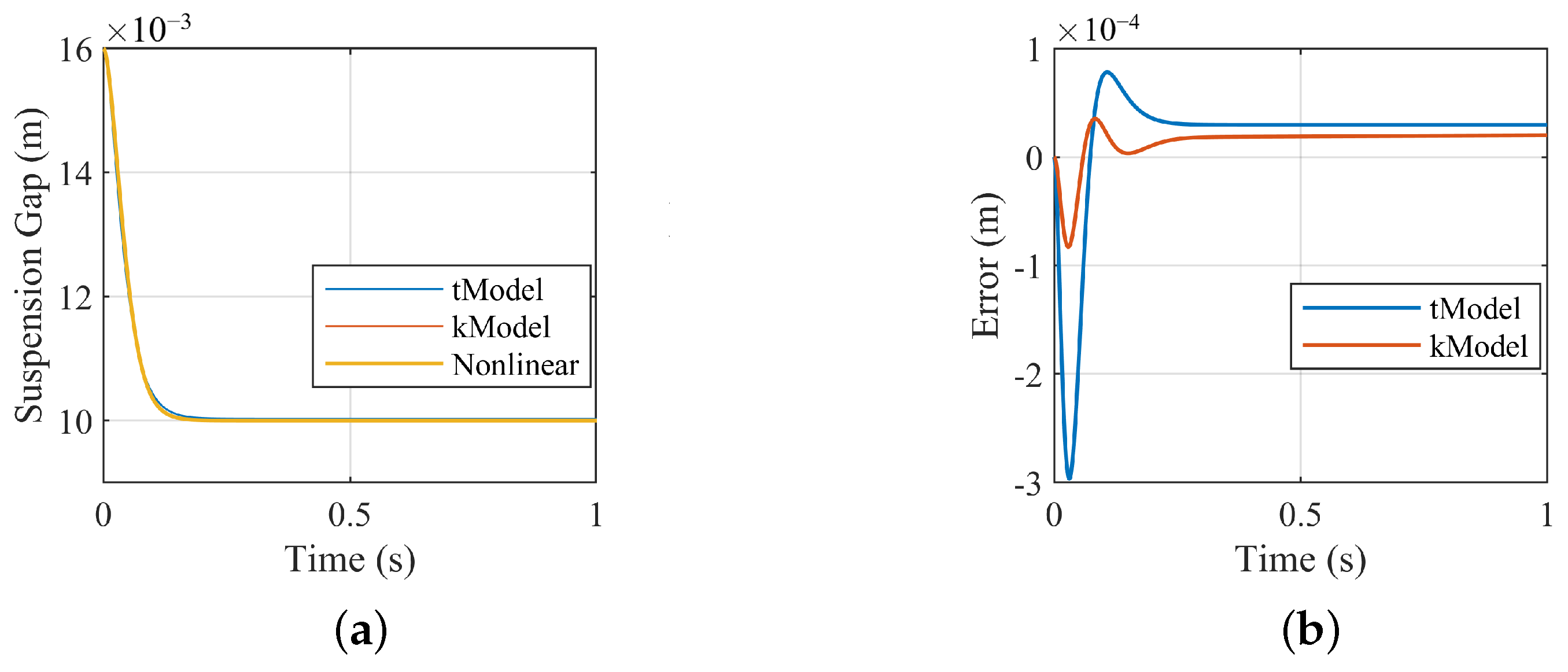
    Figure 5 shows the suspension gap response of the system model, which are, respectively, the nonlinear model as (3), the linearized model by Taylor expansion as (5) (tModel), and the Koopman data-driven model (kModel), with the same controller parameters. Compared to the tModel, the data-driven model has smaller modeling errors, indicating that the high-dimensional linearized model established by the Koopman data-driven method can meet the analysis requirements for nonlinear systems.
  • Optimization of the suspension control by the data-driven model: Reconstruct the “gap-velocity” controller as Section 2.3.2, and calculate the parameters of the feedback controller. Set Q = diag(5,1,2,1), R = [5]. The result is K = [−4662.1,−143.02,−4571.02, 114.93], i 0 = 23.53 A.
    Based on the data-driven model, the ESO is designed, and the gain of the ESO is set as β = [ 1.5 × 10 3 ,   2.0 × 10 5 ,   2.5 × 10 7 ] .
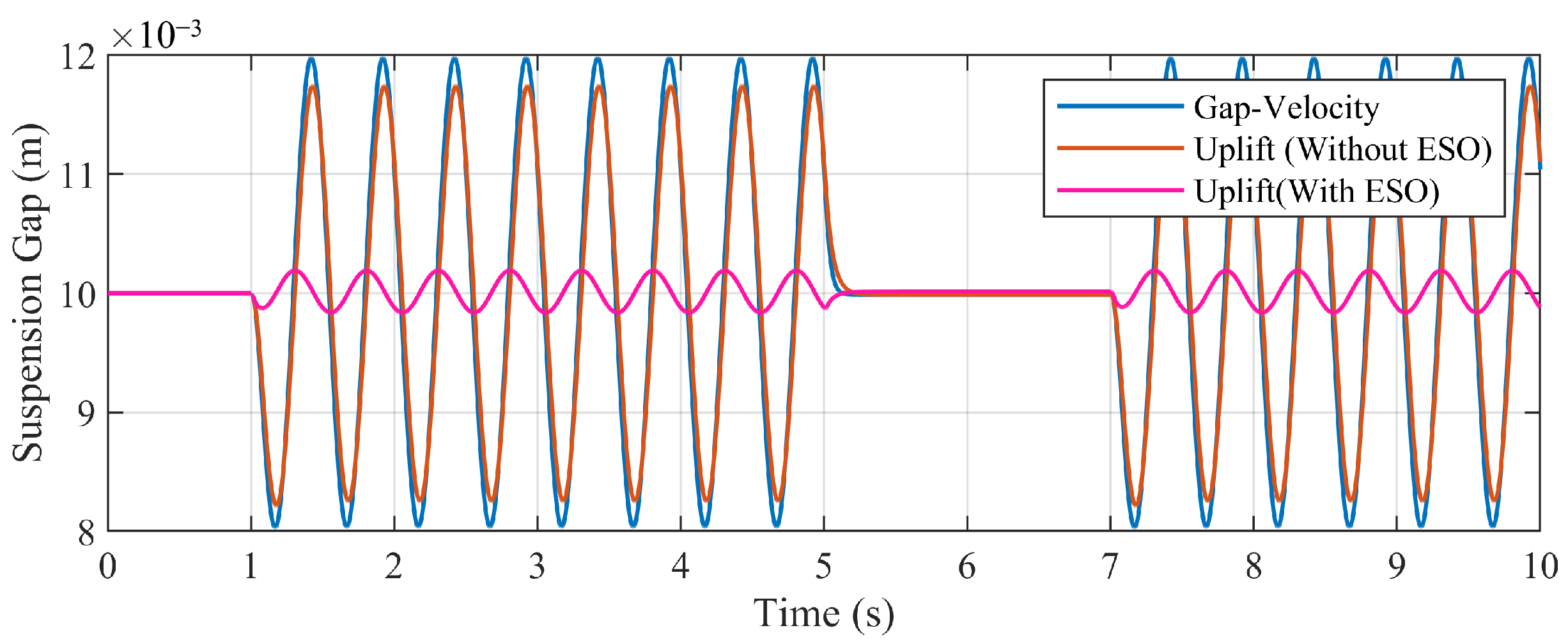
    According to (3), applying a disturbance signal to the current input is equivalent to applying an external disturbance to the system. After the suspension system has stabilized, a sinusoidal disturbance (2 Hz, 1 A) is applied to the simulation model. Figure 6 shows the response of the air gap of the magnet when the system uses the original “gap-velocity” controller and uplifted controller (without ESO compensation and with ESO compensation).
    By the uplifted feedback controller, based on the data-driven model, the control parameters are further optimized, reducing the offset of the gap response from ±1.98 mm to ±1.78 mm. Compared to the linearized tModel, the Koopman model preserves the nonlinear characteristics of the system beyond the equilibrium point, thereby enabling further optimization of the control parameters.
    Moreover, with the disturbance compensation from the ESO, the simulation result shows a significant reduction in the peak-peak fluctuation of the suspension gap response, as the offset decreases to ±0.16 mm.
In summary, for the suspension system, especially those with unknown parameters, using the Koopman data-driven modeling method can establish a more accurate model. This approach allows for the controller parameter optimization and observer design based on the system data-driven model, enhancing the control performance of the suspension system.

3.2. Data-Driven Modeling Experiment on Maglev Test Bench

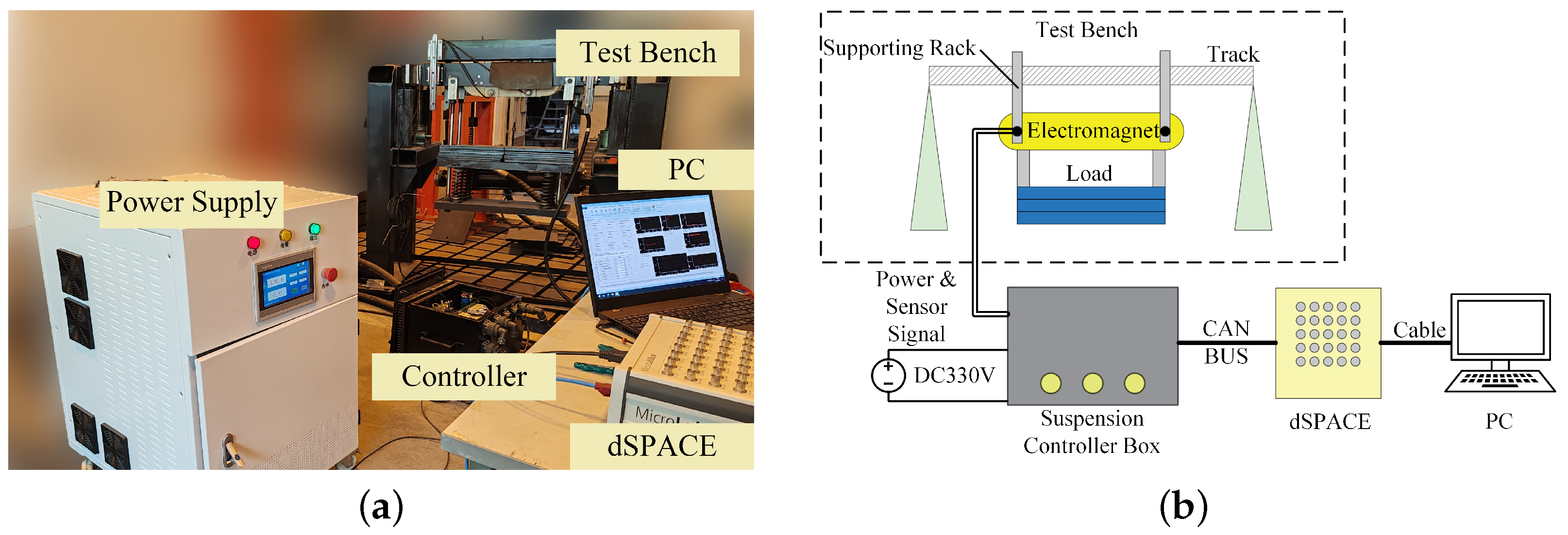
To further verify the data-driven method using experiments, this section conducts modeling and control parameter optimization experiments on the suspension system through the single-magnet maglev test bench as shown in Figure 7.
The test bench comprises a suspension electromagnet, suspension sensors (air gap and acceleration), and a load. The sensor signal is filtered and input into the control program running on the dSPACE terminal. The control program processes the current control signal and sends it to the suspension controller box. The magnet is controlled by the chopper circuit in the controller box.
The experiment is conducted as follows:
  • Data collection and data-driven modeling: To solve the noise interference problem and the input saturation of the test bench system, an integral feedback loop is introduced based on the original “gap-velocity” controller, forming a discrete PID controller (31) and (32).
    i ( k ) = i 0 [ KE ( k ) + k i j = 0 k ( δ c ( j ) δ 0 ) ]
    E ( k ) = [ δ c ( k ) δ 0 , δ c ( k ) δ c ( k 1 ) T s ] T
    where T s is the sampling time of the system, K is tuned by experience, as K = [−6000,−750], while the parameter k i = −430 remains unchanged.
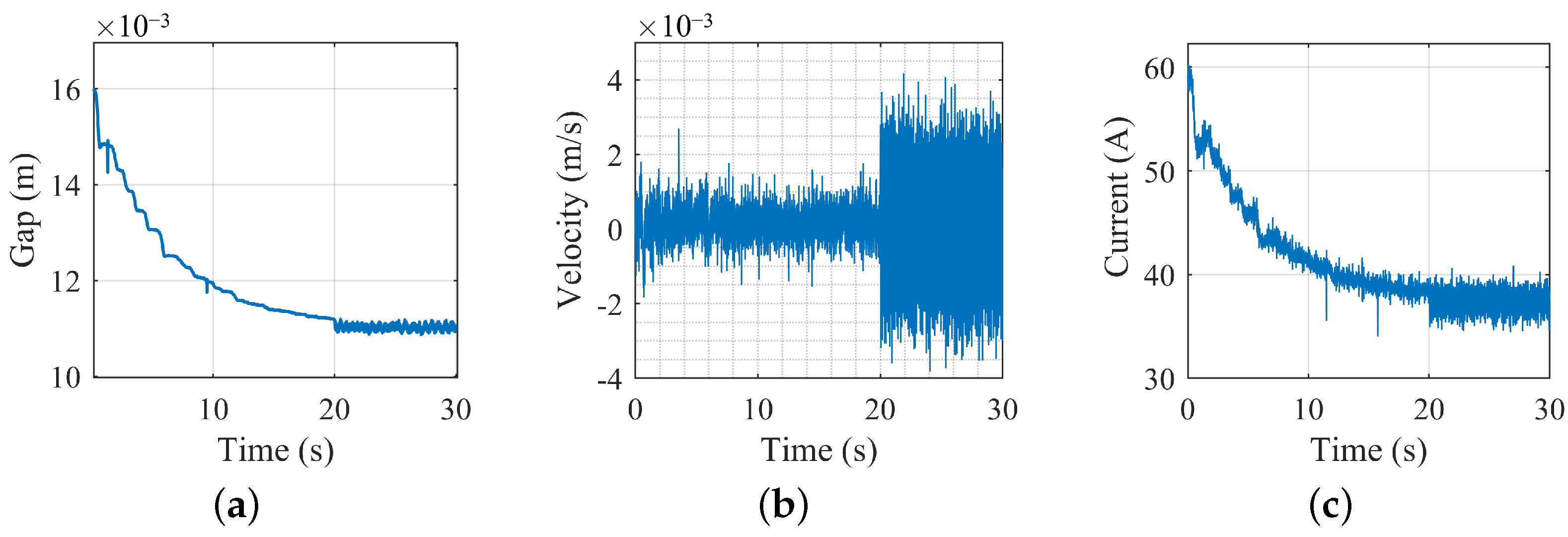
    Collect the state and input data from the system (apply disturbance after the magnet is stabilized) of several sets. The sampling time is 0.001 s, and 30 s of data are collected each time. The suspension gap is measured directly by the sensor, while the velocity is indirectly measured by integrating acceleration signals from the sensor. For example, one set of the test data collections is shown in Figure 8.
    With the collected data, the system matrices can be calculated as (20) and (21), and the high-dimensional linearized model is constructed. The feedback parameter matrix K is calculated by the LQR method, whose parameters are Q = diag(5,1,2,1) and R = [5]. The result is K = [−5755.6, −935.96, −96,578, 6370], and the current of the equilibrium point ( δ 0 = 11 mm) is i 0 = 37.43 A.
  • Test of control optimization by data-driven model: Set the reference gap as δ 0 = 11 mm and conduct a suspension test by the uplifted feedback controller on the test bench. Figure 9 shows the suspension gap response of the bench after using the optimized controller. The magnet remains relatively stable.
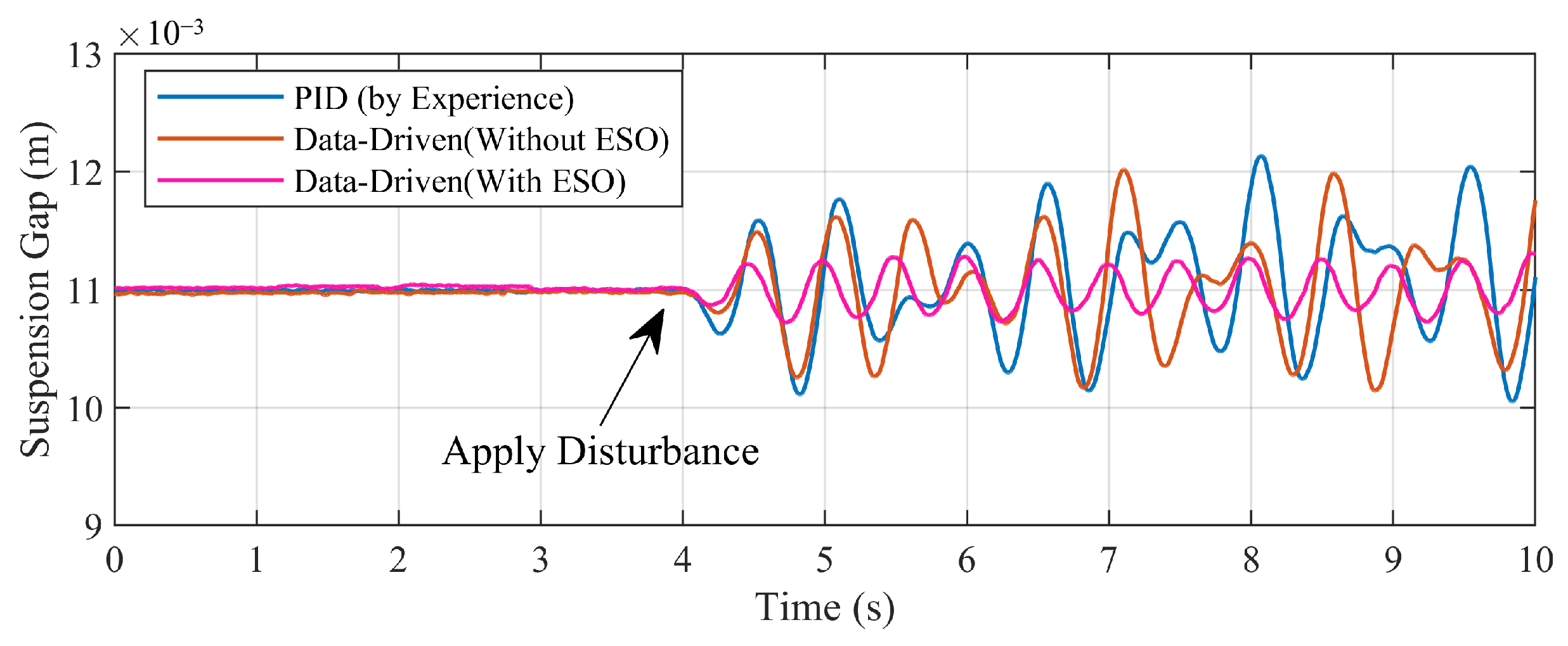
    The ESO is constructed with the gain β = [ 1.5 × 10 3 ,   2.0 × 10 5 ,   2.5 × 10 7 ] based on the data-driven model, to compensate for the suspension current. After the suspension system stabilizes, a sinusoidal disturbance current (2 Hz, 1 A) is applied to the system. Figure 10 shows the gap response of the system, comparing the PID (by experience) and the data-driven method (before and after using the ESO). Compared to the experience-based PID controller, the feedback controller based on the data-driven model has better performance, decreasing the fluctuation by 12.9% for the maximum, and 14.3% for the IAE index. In addition, after adopting the ESO compensation, the fluctuation of the suspension gap further decreased by 72.3% of the maximum, and 58.5% for the IAE index, as shown in Table 1. In summary, the data-driven method with compensation has a better performance under the external force disturbance, which can provide a maximum reduction of 75.0% of the system fluctuation in total.
The above results indicate that using the data-driven modeling methods enables the optimization of the control parameters and the design of state observers, by modeling the suspension system with uncertain parameters, which can significantly enhance the system’s response to the disturbance.

4. Data-Driven Modeling Method for the Operation Scenarios of Maglev Trains

4.1. Multi-DOF Model of the Suspension System

For the engineering application of maglev trains, it is necessary to consider the influence of the variation of the system factors, such as the suspension system’s structure and external track irregularities. This section focuses on the practical scenarios of maglev trains, considering the actual structure of the train, and establishes a multi-DOF model of the suspension system.
For the high-speed maglev train as an example, Figure 11 shows the structure of the suspension system of the train. Each vehicle contains four suspension chassis, and vibrations are transmitted between the chassis and the vehicle body through air springs. Correspondingly, the suspension electromagnet is mounted between the two arms of the chassis, which are connected by plate springs.
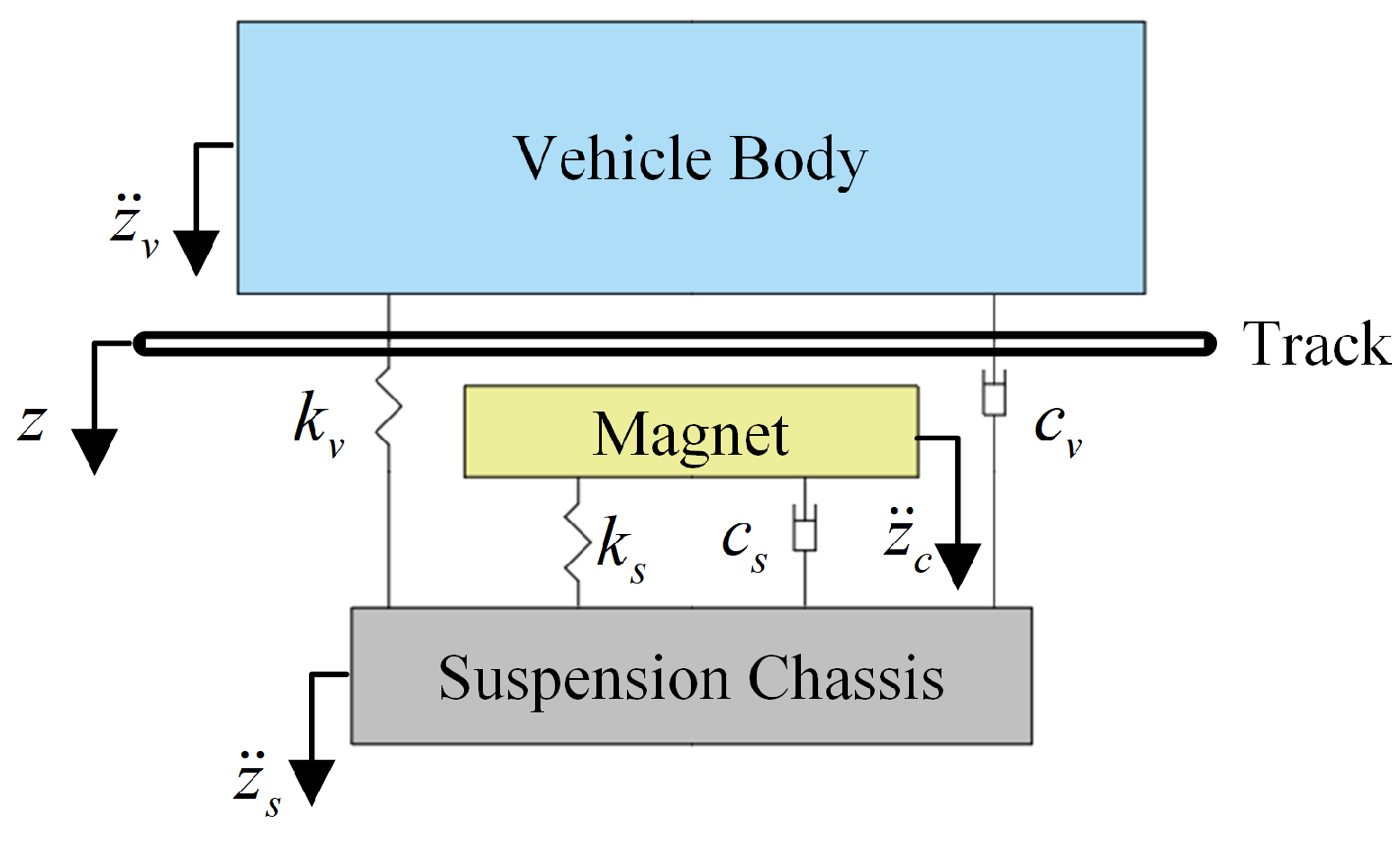
Select one side of the magnet on the chassis arm, Figure 12 shows the multi-DOF suspension system model considering the spring structures.
Set z c , z s , and z v as the vertical position (relative to the horizontal plane of the track) of the magnet, chassis, and vehicle body, the dynamic expression of the system is as follows:
m c z ¨ c = m c g + k s ( z s z c ) + c s ( z ˙ s z ˙ c ) F M m s z ¨ s = m s g + k s ( z c z s ) + c s ( z ˙ c z ˙ s ) + k v ( z v z s ) + c v ( z ˙ v z ˙ s ) m v z ¨ v = m v g + k v ( z s z v ) + c v ( z ˙ s z ˙ v )
Table 2 is the parameter definition of the system model, and the masses of the chassis and the vehicle body are averaged over each single suspension magnet.

4.2. Rolling-Update Modeling Based on the Koopman Operator

The aforementioned Koopman data-driven method requires the complete collection of the systems states before system modeling, which is an offline approach. In engineering applications, the suspension system is affected by its performance changes and external uncertainty disturbances. The offline modeling method cannot fully reflect the parameter changes during the system operation process.
In this section, the EDMD method is improved by a rolling-update modeling algorithm: the system states and input are collected in a rolling manner, and the system model is compared with the actual system errors to determine whether to update the system model. This enables the continuous modeling and updating of the data-driven model of the suspension system. Furthermore, through the data-driven model, online rolling optimization of the suspension control parameters is achieved to improve the stability of the suspension system.
The process of the rolling-update data-driven method is as follows:
  • After the system starts operating, sample the system’s state data and input data to construct data matrices X and U for N 0 sets, and perform Koopman modeling according to Section 2.3 to obtain the system model matrices A, B, and C.
  • Continue to collect data of N s sets ( N s < N 0 ), to replace the first N s data sets in X and U (The total amount of collected data remains N 0 ).
    Select the first N 0 − 1 data sets to construct uplifted-state data matrix Z s 1 and input data matrix U s 1 ; and select 2~ N 0 data sets to construct output data matrix X s (as the reference data matrix).
    Based on the data-driven model constructed in Step 1, calculate the system output X c as:
    X c = CAZ s 1 + CBU s 1
  • Calculate the accuracy of the model as | X c X s | . If the result is bigger than threshold ϵ , the update of the system is required. The system model is reconstructed by (20)~(21) using the new data matrices. Otherwise, the system model remains unchanged. Repeat the above process until the system stops.
Compared to the offline modeling method, the rolling-update model method can model the system’s states quickly, reflecting the dynamic changes in the system parameters, which enables further optimize the suspension control parameters. By the evaluating the accuracy of the model, the computational cost of the method is reduced, making the online update more feasible for practical applications.

4.3. Data-Driven Simulation of the Suspension System under Track Irregularities

4.3.1. Influence of Track Irregularities on the Suspension System

The track irregularity is an important factor affecting the stability of the suspension system. The system model established above is only applicable to rigid track conditions. During the train operation, the suspension system is affected by track irregularities. Moreover, the maglev transportation system applies the “beam-track” integrated structure, and the track beam is deformed by reaction forces, resulting in periodic irregularities. In addition, factors such as manufacturing accuracy and track wear cause random irregularities on the track plane. These factors cause fluctuations in the suspension gap [21], leading to vertical vibrations of the vehicle.
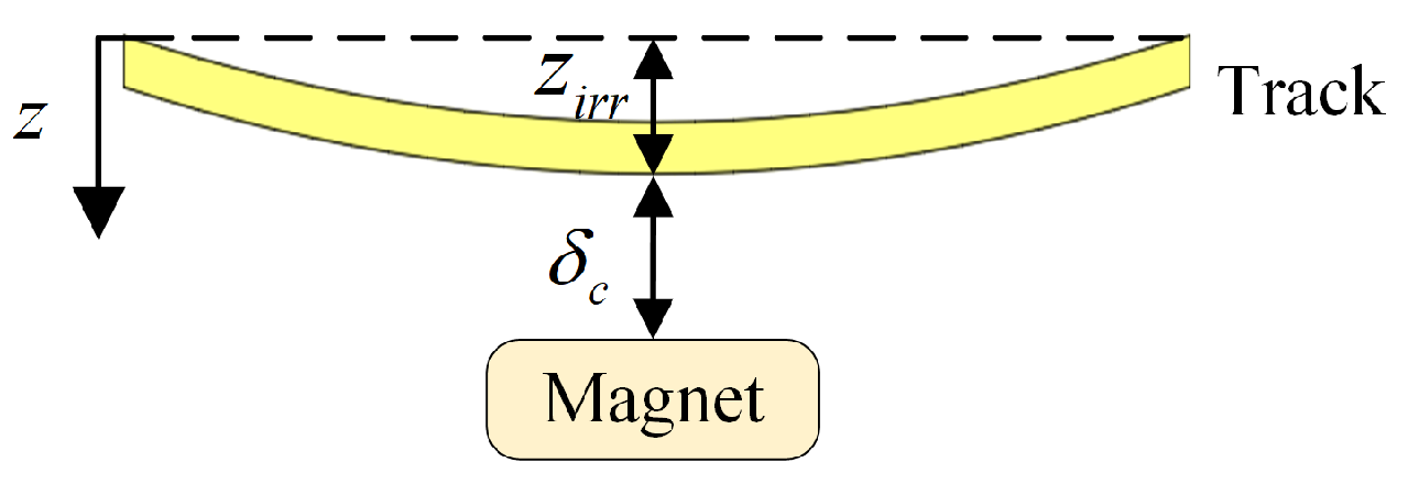
Figure 13 shows the relationship between the track irregularity and the suspension gap [22]. Set the deform of the track as z i r r , the gap between the magnet and the track is δ c . The absolute position of the suspension system z c is:
z c = δ c + z i r r
According to (33), to ensure stability during the train operation, it is necessary to reduce the fluctuation of z c , to reduce the excitation of the track irregularities to vertical vibration of the vehicle.

4.3.2. Simulation of Data-Driven Modeling under the Track Irregularities

Construct the suspension system model as (33) in Simulink, and suspension simulation is conducted by offline data-driven method (use the system model as the initial value without updating) and rolling-update method to study the system response under the track irregularities.
Set the simulation time as 10 s, the sampling time is 0.001 s, and the reference gap is δ 0 = 10 mm. Collect the gap, the velocity, and the current input of the suspension magnet, calculate the system model as Section 2.3, and the initial feedback control parameters are K = [−8980, −51, −11,290, 104], the equilibrium current is i 0 = 32.00 A, which are calculated as (23) and (25).
After the system is stabilized, the track irregularity signal of 10 s is applied, to simulate the track disturbance under the operation at 600 km/h. The irregularity signal is based on the real-measured data from the Shanghai Maglev Line in [23], considering both periodic and random irregularity factors. By the inversion of the spectrum of the track irregularity data, the irregularity waveform is obtained as Figure 14. The frequency range of the waveform is 0.1667~166.7 Hz.
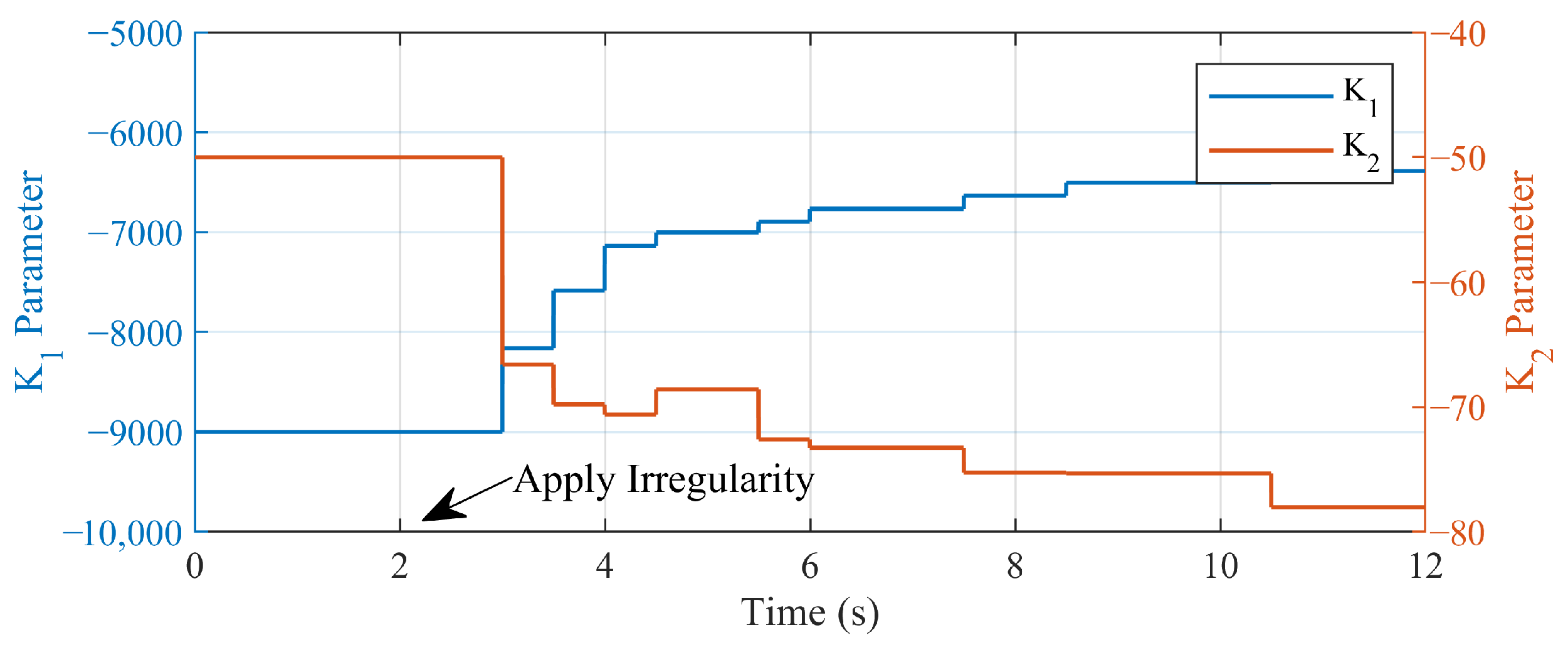
For the rolling-update method, after the disturbance is applied, the update of the data-driven model is activated, to optimize the control parameters online. Set the sample number is N 0 = 2000 and N s = 500 (Keep the data of 2 s to data-driven modeling, and update every 0.5 s), the threshold of system update is ϵ = 5 × 10 4 m. The simulation is conducted in Simulink, and the average time of each calculation of the rolling-updating is 0.0046 s, which is shorter than the updating cycle time, indicating that the rolling-update method is feasible under the simulation environment. With the rolling-update method, the control parameters (e.g., the first and second item of K) changes are shown in Figure 15.
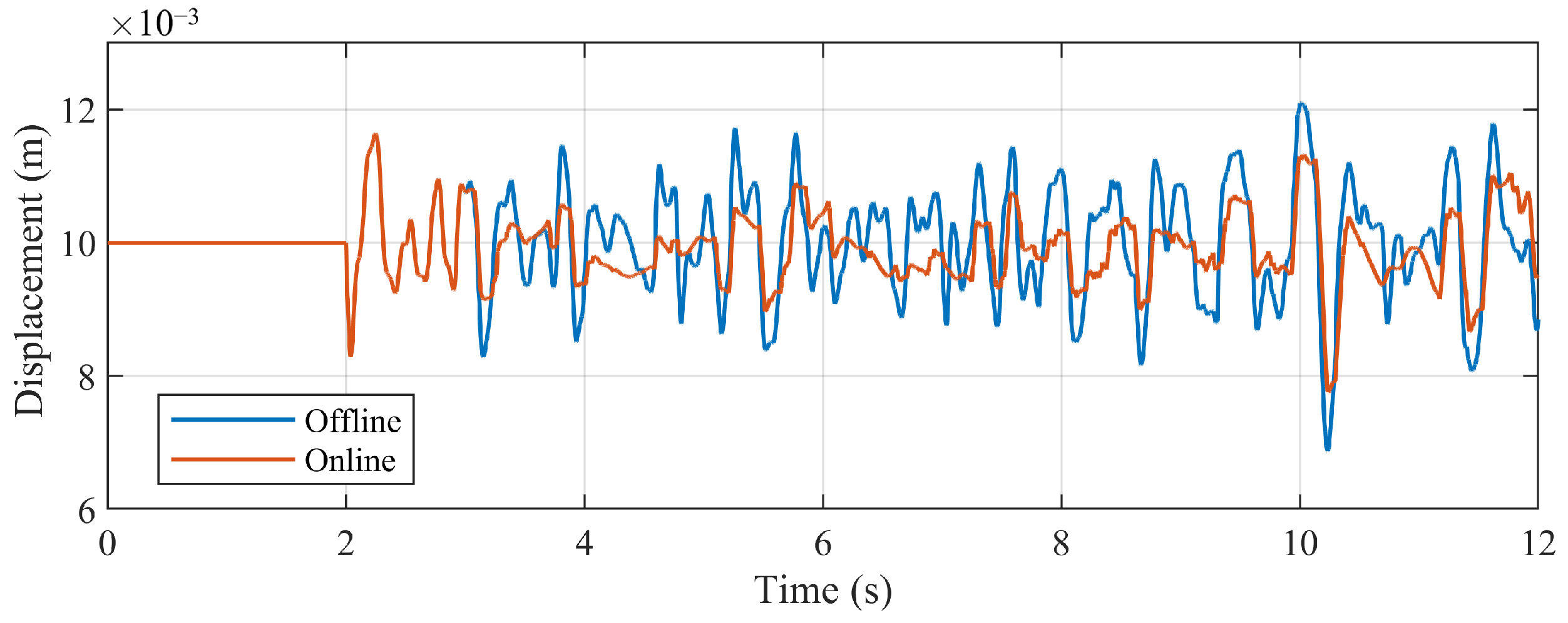
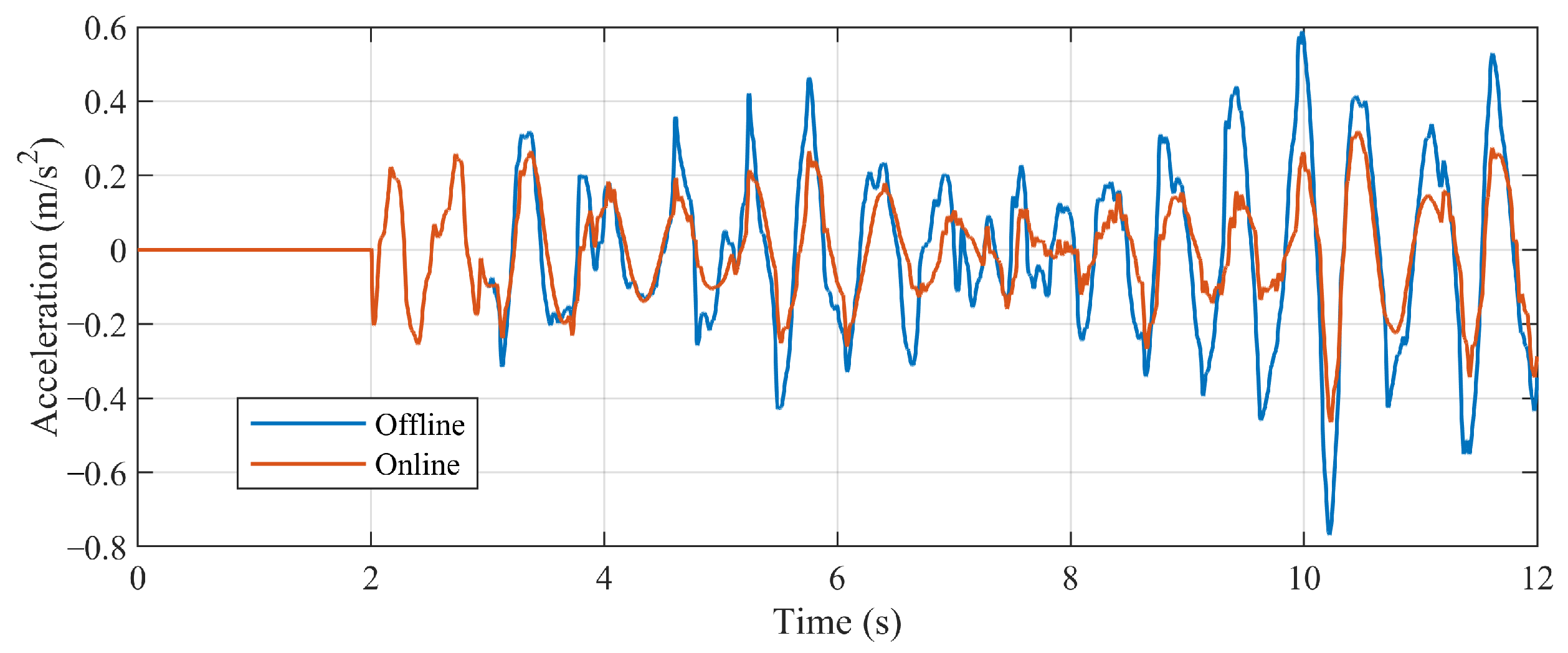
During the operation of the train, the vertical displacement of the suspension electromagnet z c and the response of the vertical vibration acceleration of the vehicle body z ¨ v are important factors affecting the stability of the train: When the vertical movement of the suspension magnet is too large, the magnet will hit the track, causing the failure of suspension control. The vibration of the vehicle body under external disturbances affects the comfort of the train. Taking these two variables as observation objects, the simulation results are as follows:
  • The vertical displacement of the suspension electromagnet: Figure 16 shows the vertical displacement of the suspension magnet. By the rolling-update method, as the system model is updated, the control parameters change, and the offset of the vertical displacement of the suspension electromagnet is significantly reduced. Calculate the integral absolute error (IAE) of the displacement response of the suspension magnet (Table 3), the result shows that after applying the rolling-update method, the IAE decreases, indicating that the response of the suspension system behaves better under the track irregularities.
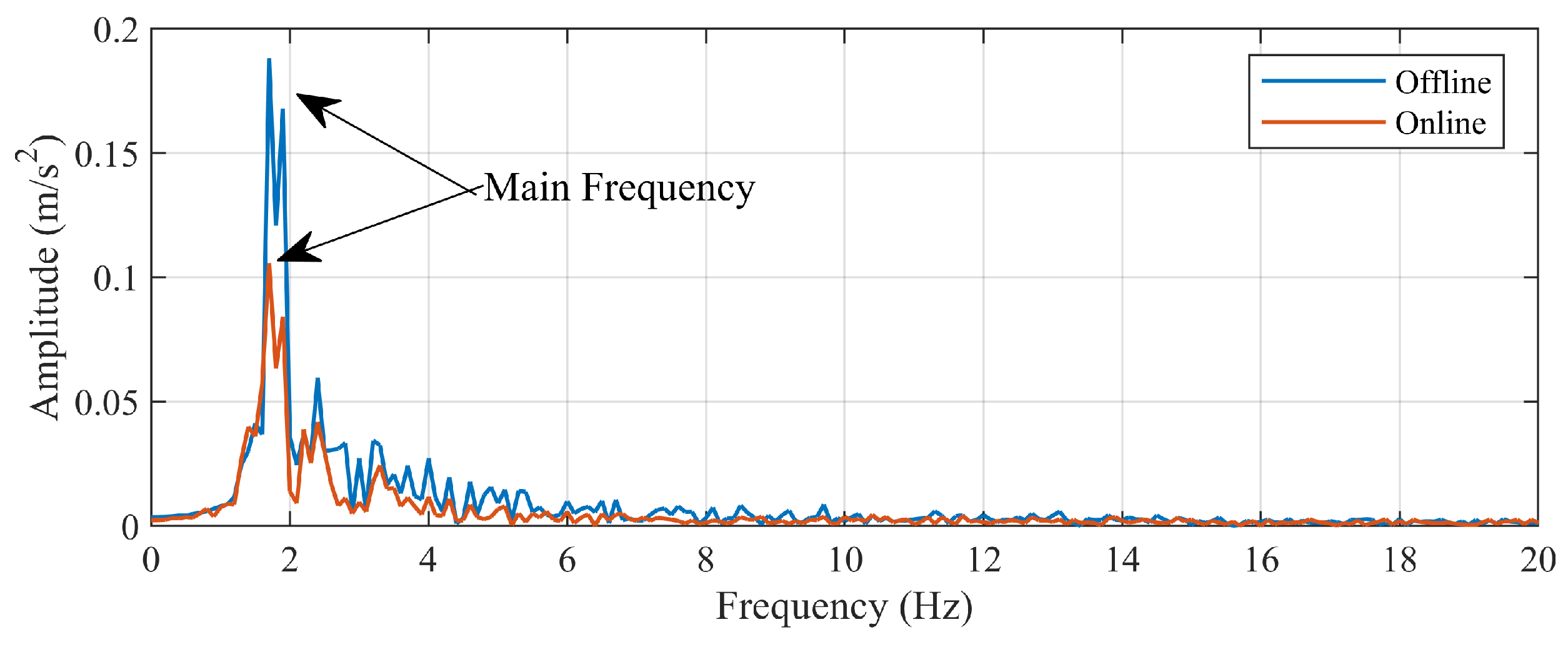
  • The vibration acceleration of the vehicle body: Figure 17 and Figure 18, and Table 4 show the time-domain response and frequency spectrum of the vertical vibration acceleration of the vehicle body. From the time-domain response, it can be seen that compared to the offline model, the vibration acceleration of the vehicle body with the rolling-update parameters shows a decreasing trend, and the maximum amplitude decreases by about 40.0%. Conducting the variance analysis on vibration acceleration, the result shows that with the rolling-update method, the variance of the acceleration decreased, which means the fluctuation of acceleration response is smaller.
    Spectral analysis is conducted on the acceleration response as Figure 18, and the acceleration amplitude of the vehicle at the main frequency (1.7 Hz) decreased from 0.188 m/s2 to 0.100 m/s2, decreasing 46.8%, while the amplitudes of other frequency components also decreased. The above results indicate that after the rolling update of the system model, the vibration amplitude of the vehicle body decreases when the system is disturbed by track irregularities.
In summary, the rolling-update data-driven method for real-time modeling of the suspension system with parameter changes achieves online optimization and tuning of the control parameters. This method improves the control performance of the suspension system under disturbance conditions such as track irregularities, thereby enhancing the adaptability and robustness against disturbances of the system.

5. Conclusions

This article researches the suspension system control of the maglev train and proposes a data-driven method for the system based on the Koopman operator theory, which can accurately model the suspension system with uncertain parameters. Based on the data-driven model, control parameter optimization and observer design are carried out. Compared to the traditional linear feedback control approach, the the data-driven control method can reduce the fluctuation of the system under disturbed conditions, demonstrating superior control performance.
Considering the complex operation situations and dynamic changing of the maglev train, the response of the multi-DOF model of the suspension system is studied, focusing on track irregularity disturbances. The proposed rolling-update modeling method enables online modeling of the system. By the optimization of the controller based on the online-update model, this method reduces the gap fluctuation of the magnet by 40.0%, and the vibration acceleration of the vehicle body is reduced by 46.8%. These improvements enhance the stability and anti-disturbance performance of the suspension system in the operating situations.
Future work will focus on applying the proposed methodology to the maglev trains in real operation, to investigate the robustness and feasibility of the Koopman data-driven method. Additionally, further research will aim to improve the data-driven process for better modeling accuracy and less calculation cost.

Author Contributions

Conceptualization, P.H. and J.X.; methodology, P.H.; software, P.H. and W.W.; validation, P.H., L.R. and W.W.; formal analysis, Y.S.; investigation, J.X.; resources, J.X.; data curation, J.X. and L.R.; writing—original draft preparation, P.H.; writing—review and editing, Y.S.; visualization, Y.S.; supervision, J.X. and G.L.; project administration, J.X. and G.L.; funding acquisition, J.X. All authors have read and agreed to the published version of the manuscript.

Funding

This research was funded by the National Natural Science Foundation of China, grant number 52232013; the National Natural Science Foundation of China, grant number 52072269; the National Key R&D Program of China, grant number 2023YFB4302500-02.

Data Availability Statement

The data presented in this study are available on request from the corresponding author.

Acknowledgments

The authors would thank the National Maglev Transportation Engineering R&D Center for the support of the research and experiments.

Conflicts of Interest

The authors declare no conflicts of interest.

Abbreviations

The following abbreviations are used in this manuscript:
EMSElectromagnetic Suspension
DMDDynamic Mode Decomposition
EDMDExtended Dynamic Mode Decomposition
tModelthe linearized model by Taylor expansion
kModelthe Koopman data-driven model
IAEIntegral Absolute Error
DOFDegree-of-Freedom

References

  1. Wang, K.R.; Luo, S.H.; Zhang, J.Y.; Ma, W.H. Maglev System Control Algorithm and the Related Dynamic Analysis. In Proceedings of the ICRT 2017: Railway Development, Operations, and Maintenance, Chengdu, China, 10–12 July 2017; American Society of Civil Engineers: Reston, VA, USA, 2018; pp. 689–698. [Google Scholar]
  2. Chen, Q.; Tan, Y.; Li, J.; Mareels, I. Decentralized PID Control Design for Magnetic Levitation Systems Using Extremum Seeking. IEEE Access 2018, 6, 3059–3067. [Google Scholar] [CrossRef]
  3. Zhu, Y.H.; Yang, Q.; Li, J.; Wang, L.C. Research on Sliding Mode Control Method of Medium and Low Speed Maglev Train Based on Linear Extended State Observer. Machines 2022, 10, 644. [Google Scholar] [CrossRef]
  4. Yaseen, H.M.S.; Siffat, S.A.; Ahmad, I.; Malik, A.S. Nonlinear adaptive control of magnetic levitation system using terminal sliding mode and integral backstepping sliding mode controllers. ISA Trans. 2022, 126, 121–133. [Google Scholar] [CrossRef]
  5. Sun, Y.G.; Qiang, H.Y.; Wang, L.; Ji, W.; Mardani, A. A Fuzzy-Logic-System-Based Cooperative Control for the Multielectromagnets Suspension System of Maglev Trains With Experimental Verification. IEEE Trans. Fuzzy Syst. 2023, 10, 3411–3422. [Google Scholar] [CrossRef]
  6. Zhu, J.Q.; Ge, Q.X.; Sun, P.K. Extended State Observer-Based Sensorless Control for High-Speed Maglev Application in Single-Feeding Mode and Double-Feeding Mode. IEEE Trans. Transp. Electrif. 2022, 8, 1350–1361. [Google Scholar] [CrossRef]
  7. Wang, H.; Zhong, X.B.; Shen, G. Levitation control strategy for maglev on elastic track based on Kalman filter. J. Cent. South Univ. Sci. Technol. 2014, 45, 965–972. [Google Scholar]
  8. Yang, Q.; Chi, Z.X.; Wang, L.C. Influence and Suppression Method of the Eddy Current Effect on the Suspension System of the EMS Maglev Train. Machines 2022, 10, 476. [Google Scholar] [CrossRef]
  9. Ni, F.; Dai, Y.W.; Xu, J.Q.; Rong, L.J.; Zheng, Q.H. Performance Evaluation of the Suspension System on Maglev Trains Based on Measurement Data. Metrol. Meas. Syst. 2024, 31, 115–133. [Google Scholar] [CrossRef]
  10. Li, X.; Zhu, H.; Ma, J.; Teo, T.J.; Teo, C.S.; Tomizuka, M.; Lee, T.H. Data-Driven Multiobjective Controller Optimization for a Magnetically Levitated Nanopositioning System. IEEE/ASME Trans. Mechatronics 2020, 25, 1961–1970. [Google Scholar] [CrossRef]
  11. Chen, Q.; Tan, Y.; Li, J.; Oetomo, D.; Mareels, I. Model-Guided Data-Driven Decentralized Control for Magnetic Levitation Systems. IEEE Access 2018, 6, 43546–43562. [Google Scholar] [CrossRef]
  12. Proctor, J.L.; Brunton, S.L.; Kutz, J.N. Generalizing Koopman Theory to Allow for Inputs and Control. SIAM J. Appl. Dyn. Syst. 2018, 17, 909–930. [Google Scholar] [CrossRef] [PubMed]
  13. Korda, M.; Mezic, I. Linear predictors for nonlinear dynamical systems: Koopman operator meets model predictive control. Automatica 2018, 93, 149–160. [Google Scholar] [CrossRef]
  14. Zhao, D.; Yang, X.; Li, Y.; Xu, L.; She, J.; Yan, S. A Kalman-Koopman LQR Control Approach to Robotic Systems. IEEE Trans. Ind. Electron. 2024, early access. [CrossRef]
  15. Korda, M.; Susuki, Y.; Mezic, I. Power grid transient stabilization using Koopman model predictive control. IFAC-PapersOnLine 2018, 51, 297–302. [Google Scholar] [CrossRef]
  16. Wen, T.; Long, Z.Q.; Zhou, X.; Hu, Y.P. Study on Data-Driven Control of Maglev Train Levitation System Based on Koopman Linear Reconstruction. Proc. Rom. Acad. Ser. A 2022, 23, 161–170. [Google Scholar]
  17. Calderón, H.M.; Schulz, E.; Oehlschlägel, T.; Werner, H. Koopman Operator-based Model Predictive Control with Recursive Online Update. In Proceedings of the 2021 European Control Conference (ECC), Rotterdam, The Netherlands, 29 June–2 July 2021; pp. 1543–1549. [Google Scholar]
  18. Wang, D.N.; Meng, F.W.; Meng, S.Y. Linearization Method of Nonlinear Magnetic Levitation System. Math. Probl. Eng. 2020, 23, 9873651. [Google Scholar] [CrossRef]
  19. Williams, M.O.; Kevrekidis, I.G.; Rowley, C.W. A Data-Driven Approximation of the Koopman Operator: Extending Dynamic Mode Decomposition. J. Nonlinear Sci. 2015, 25, 1307–1346. [Google Scholar] [CrossRef]
  20. Hou, T.; Tang, L.; Niu, H.X. Data-driven Speed Compound Control of High-speed Train. J. Transp. Syst. Eng. Inf. Technol. 2023, 23, 1307–1346. [Google Scholar]
  21. Shi, J.; Fang, W.S.; Wang, Y.J.; Zhao, Y. Measurements and analysis of track irregularities on high speed maglev lines. J. Zhejiang Univ.-Sci. A 2014, 15, 385–394. [Google Scholar] [CrossRef]
  22. Sun, Y.G.; He, Z.Y.; Xu, J.Q.; Sun, W.; Lin, G.B. Dynamic analysis and vibration control for a maglev vehicle-guideway coupling system with experimental verification. Mech. Syst. Signal Process. 2023, 15, 109954. [Google Scholar] [CrossRef]
  23. Liu, M.B.; Ye, F.; Zeng, G.F. Research of the track irregularity spectrum of Shanghai high-speed transrapid demonstration line. Veh. Syst. Dyn. 2024, 62, 2054–2078. [Google Scholar] [CrossRef]
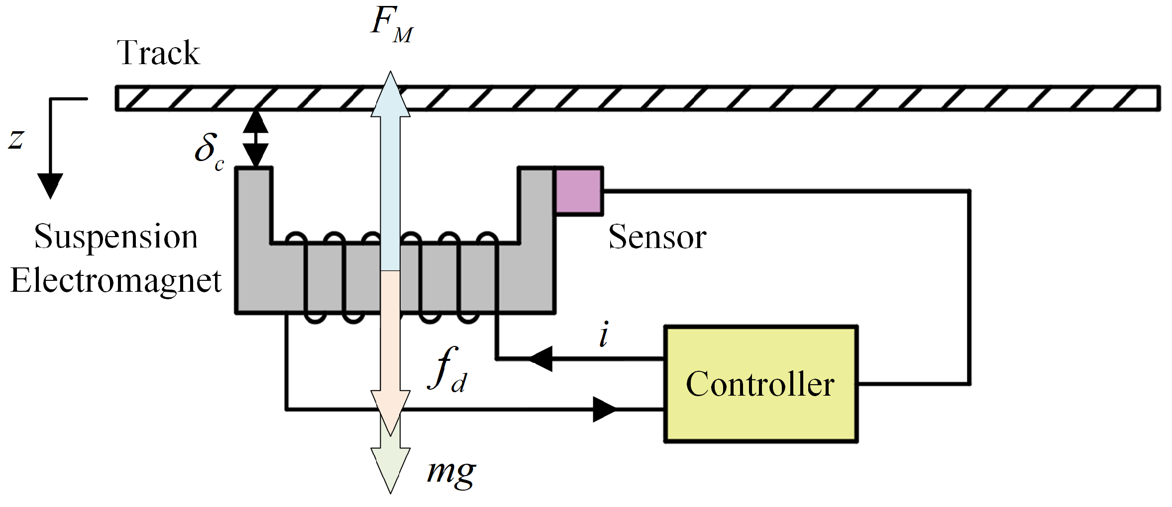
Figure 1. The single-electromagnetic model.
Actuators 13 00397 g001
Figure 2. The “gap-velocity” feedback controller.
Actuators 13 00397 g002
Figure 3. The data-driven modeling method of the suspension system.
Actuators 13 00397 g003
Figure 4. The control schema of the suspension system.
Actuators 13 00397 g004
Figure 5. Suspension gap of the system model: (a) The gap response; (b) Response error comparison.
Actuators 13 00397 g005
Figure 6. Suspension gap of the system model of different controller.
Actuators 13 00397 g006
Figure 7. The single-magnet maglev test bench: (a) The test bench; (b) The connection of the bench.
Actuators 13 00397 g007
Figure 8. The states and input from the test bench (example): (a) Gap; (b) Velocity; (c) Current.
Actuators 13 00397 g008
Figure 9. The suspension gap of the test bench (by uplifted feedback controller).
Actuators 13 00397 g009
Figure 10. The suspension gap of the test bench (with external force disturbance).
Actuators 13 00397 g010
Figure 11. The structure of the suspension system of high-speed maglev trains.
Actuators 13 00397 g011
Figure 12. Multi-DOF suspension system model.
Actuators 13 00397 g012
Figure 13. Relation of the track irregularity and the suspension gap.
Actuators 13 00397 g013
Figure 14. The waveform of the track irregularity.
Actuators 13 00397 g014
Figure 15. The change of the control parameters (example).
Actuators 13 00397 g015
Figure 16. The vertical displacement of the suspension magnet.
Actuators 13 00397 g016
Figure 17. The vibration acceleration response of the vehicle body (time-domain response).
Actuators 13 00397 g017
Figure 18. The vibration acceleration response of the vehicle body (spectrum).
Actuators 13 00397 g018
Table 1. Comparison of the experiment result of the test bench.
Type of ControllerMaximum OffsetIntegral Absolute Error
PID (By experience)−0.93~1.16 mm2.554
Data-Driven (Without ESO)−0.85~1.01 mm2.164
Data-Driven (With ESO)−0.28~0.28 mm0.897
Table 2. Parameter definition of the system model.
SymbolParameterValue
AArea of Magnet Pole0.115 m2
NNumber of Turns of Magnet270
m c Mass of Magnet300 kg
m s Mass of Suspension Chassis450 kg
m v Mass of Vehicle Body2000 kg
k v Rigidity of Air Spring 2 × 10 5  N/m
c v Damping of Air Spring 2 × 10 3  N·s/m
k s Rigidity of Plate Spring 8 × 10 6  N/m
c s Damping of Plate Spring 2 × 10 4 N·s/m
Table 3. Comparison of the experiment result of the test bench.
Model ParameterMaximum OffsetIntegral Absolute Error
Offline Data-Driven−3.12~2.10 mm6.813
Online Rolling-Update−2.24~1.64 mm4.374
Table 4. Comparison of the experiment result of the test bench.
Model ParameterMaximum AccelerationVariance
Offline Data-Driven−0.7678~0.5884 m/s20.0435 (m/s2)2
Rolling-Update−0.4638~0.3177 m/s20.0159 (m/s2)2
Disclaimer/Publisher’s Note: The statements, opinions and data contained in all publications are solely those of the individual author(s) and contributor(s) and not of MDPI and/or the editor(s). MDPI and/or the editor(s) disclaim responsibility for any injury to people or property resulting from any ideas, methods, instructions or products referred to in the content.