1. Introduction
Due to its excellent compliance characteristics, the CM based on PAC is currently widely used in robotic grinding. As can be seen in
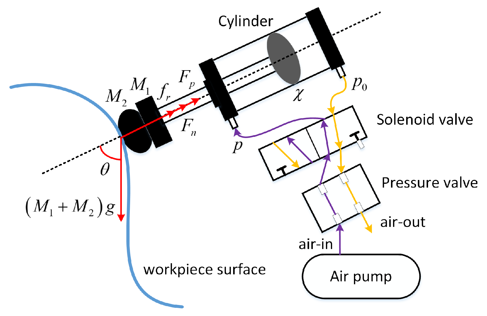
Figure 1, the grinding occurs at the contact region between the polishing tools and the workpiece surface. In practical grinding processes, the industrial robot is responsible for position control, enabling the entire grinding system to move perpendicular to the workpiece surface. Meanwhile, the PAC-driven CM is responsible for force control by controlling the air pressure so that the contact force tracks the desired contact force. This paper models the actual grinding task, ultimately leading to the scientific problem addressed in this study: the force control for the CM under external disturbances. An adaptive controller was designed for a new longitudinal resonance pneumatic cylinder in [
1]. In [
2], a saturation controller was designed using a linear ESO for the pneumatic rodless cylinder system. Ref. [
3] designed an output constrained controller based on an event-triggered mechanism for pneumatic servo systems. Ref. [
4] combined a Kalman filter and a linear quadratic regulator controller to control the soft pneumatic actuator. Although [
1,
2,
3,
4] have driven the research progress of PACs, they all focused on studying the position control of PACs. Due to the large stiffness of the robot position control, it tends to produce large impact forces on the grinding surface. Therefore, the pure robot position control does not meet the requirements of contact operations such as polishing and grinding. The following was found by Ref. [
5] that the contact force in the polishing process is the core part of the whole system, and the high-precision constant contact force control can ensure good grinding results. As a consequence, how to achieve high-precision force control for PACs is a very meaningful research topic that robot grinding needs to face.
One of the major obstacles to force control for PACs is the complex hysteresis nonlinearity between air pressure and contact force in PACs. In order to describe the hysteresis phenomenon widely existing in practical devices, many hysteresis models have been designed, which can be broadly divided into phenomenological hysteresis models [
6,
7] and physics-based hysteresis models [
8,
9]. The Prandtl–Ishlinskii (PI) model is a very popular phenomenological hysteresis model that has received a lot of attention from researchers. However, the classical Prandtl–Ishlinskii (CPI) model cannot describe asymmetric hysteresis loops. To overcome this shortcoming of the CPI model, many excellent works that describe asymmetric hysteresis loops by improving the CPI model have been conducted, for instance [
10,
11,
12,
13]. However, their analytical inverse models have numerous parameters and are very complex, which makes them difficult to implement. In [
14,
15], direct inverse models based on the polynomial forms were designed to describe the asymmetric hysteresis loops, which were simple and easy to implement since no additional analytical inverse models were required. However, the hysteresis models in [
14,
15] based on the polynomial forms have difficulty in achieving satisfactory fitting accuracy when the values in the input data of the direct inverse model are significantly larger than the values in the output data. When the values of the input data are significantly greater than the values of the output data, how to design an effective direct inverse model to compensate for the hysteresis loops is a very meaningful issue.
Due to its potential and wide application context, the force control for PACs received a lot of attention from researchers once it was successfully studied in the pioneering work [
16]. However, to reduce costs, force sensors are often not installed on the CM, making it difficult to apply closed-loop force control of PACs in practical grinding scenarios. Moreover, the significant hysteresis nonlinearities present in the contact force and pneumatic pressure make the problem of force control for CM particularly difficult. In [
17], the framework of the “planning and control” was proposed, and a robust control method based on feedback linearization was used to implement force control successfully for a compliant grinding device based on a PAC without a force sensor. Although force control was realized successfully in [
17] without access to the measured values of contact forces, its planning part used a linear relationship to fit the hysteresis nonlinearity, which could not achieve satisfactory fitting accuracy. The fitting accuracy was further improved by using a hysteresis inverse compensator to plan the desired air pressure from the desired contact force for a compliant grinding device based on PACs without a force sensor in [
18]. However, the control algorithm in [
18] was unable to achieve full-state constraints on the air pressure and the rate of change of the air pressure. Due to considerations of system performance and security, the full-state constraint problem of the CM needs to be addressed.
Based on the above observations, a “planning and control” scheme for a CM based on a double-acting cylinder (DAC) with hysteresis nonlinearity and full-state constraints is proposed in this work. The main contributions of this work are as follows.
- (1)
A novel direct inverse model that can be used for asymmetric hysteresis loops is presented in the planning part, which overcomes the drawback that most hysteresis models based on polynomial forms such as [
14,
15] cannot achieve perfect fitting accuracy when the values of the input data are significantly larger than the values of the output data.
- (2)
By constructing barrier Lyapunov functions, the full-state constraints on the air pressure and the rate of change of the air pressure in the CM are successfully achieved.
- (3)
A fuzzy ESO is developed for observing unmeasurable states and external disturbances in the CM by combining FLSs and an ESO.
2. System Description and Preliminaries
The schematic model of the DAC-driven CM is shown in
Figure 2. In this device, the pressure valve controls the expansion and contraction of the DAC to drive the movement of the load end, the pneumatic valve is modeled using a second-order transfer function as
the load side is modeled as
and the dynamic models [
17,
18] of the pressure valve and the load end are established separately considering external perturbations as follows:
where
. The representation of each term in (
1)–(
3) is explained as follows:
p: the output air pressure of the pressure valve and also the air pressure in the DAC;
u: the input voltage of the pressure valve;
: positive parameters in the dynamic model of pressure valve end;
: mass of movable end at the CM;
: mass of grinding tools at the load end;
: displacement of the piston in the cylinder;
g: gravitational acceleration;
: angle between the axial direction of the CM and the direction of gravity;
: output force of the CM;
: contact force;
: friction of the CM.
The control objective of this paper is to design a controller
u for the DAC-driven CM (
3) such that (
i) the air pressure
p tracks the desired air pressure
planned by the desired contact force
with small errors, and (
ii) the full-state constraints on the air pressure
p and the rate of change of the air pressure
are not violated.
Letting
, the dynamic model (
3) can be transformed into a general form as shown below:
where
is an unknown function,
is a lumped disturbance,
are the optimal values of
, respectively determined through identification, and
.
Assumption A1. The expected trajectory and both its derivatives are known and bounded, and satisfy , where are positive constants.
Assumption A2. The disturbance is differentiable, and , where is a positive constant.
Assumption A3 ([
19])
. There is a known constant l such that FLS, as an effective approximator for estimating unknown functions, has received much attention from researchers [
20,
21,
22,
23,
24,
25,
26]. The approximation ability of FLSs is shown in Lemma 1.
Lemma 1 ([
27])
. A fuzzy logic system (FLS) can be used to approximate a continuous function defined on a compact set Ω with a given precision such thatand the approximation error satisfies , where is the upper bound of the approximation error, represents the weight vector, and , , ⋯, denotes the fuzzy basis function vector. The fuzzy basis function is defined aswhere are fuzzy membership functions. Remark 1. In order to reduce hardware costs, the force sensor is often not installed on the polishing tool. Therefore, the measurement value of contact force is not available in the grinding process.
3. Planning of Expected Air Pressure
In this section, the expected air pressure is planned from the expected contact force by constructing a novel direct inverse model.
From the load end part of dynamic models (
3), it can be concluded that
where
is the expected contact force, which is known, and
is the expected value of
planned by the expected contact force.
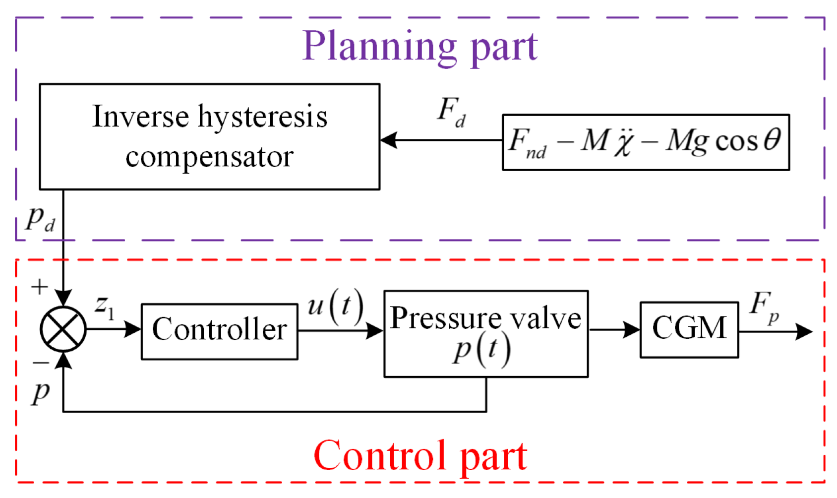
The “planning and control” scheme proposed in this work is shown in
Figure 3. Firstly,
is calculated based on
and expected contact force
. Moreover, the expected value
of the air pressure in the DAC is obtained from
through the proposed direct inverse model.
Let
denote the space of piecewise monotone continuous functions. For any input function
, the novel direct inverse hysteresis model proposed in this work is as follows:
where
and
m are the coefficients and degree of the polynomial, respectively,
are the weights satisfying
,
,
is the design parameter, and
n is the number of novel play operators
proposed as follows:
with
as the thresholds,
is a partition of
that makes the input function
monotonic on each subinterval
.
With the introduction of saturation operator
, the direct inverse model (
9) has the ability to describe the asymmetric hysteresis loop. In order to verify the ability of the proposed direct inverse model to describe asymmetric hysteresis loops, a simple example shown in
Figure 4 is given where
,
,
,
, and the saturation operator is selected as
.
Remark 2. Compared to the polynomial-based direct inverse hysteresis model in [14,15], it is the introduction of parameter that enables the direct inverse model (9) proposed in this work to achieve good fitting performance when the values in the input data are significantly greater than those in the output data. Remark 3. The selection of parameter is crucial for obtaining satisfactory fitting accuracy of the hysteresis model. When performing parameter identification, it is necessary to select the appropriate such that the values of are slightly smaller than the values of the output data of the model.
5. Experimental Validation
5.1. Compliant Testbench Driven by DAC
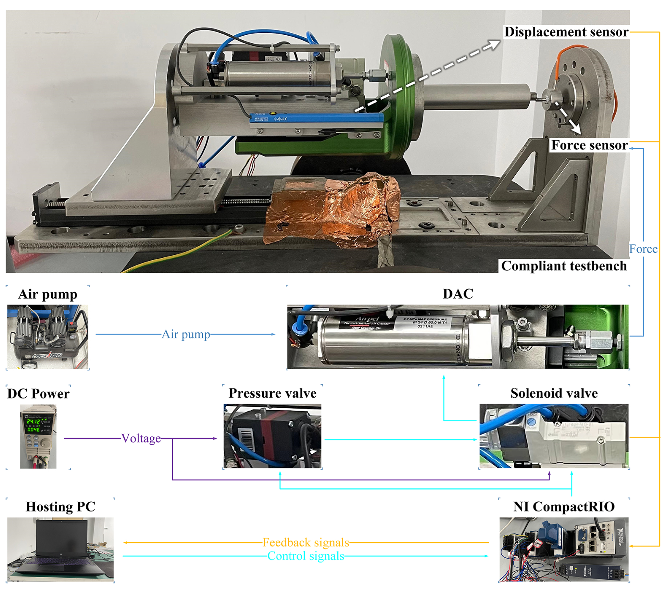
We use the experimental testbench shown in
Figure 5, in which the CM is mounted on a fixed linear guide rail. The air pressure
p inside the DAC is controlled by a pressure valve, and the intake direction of the cylinder is determined by the solenoid valve. A force sensor is used to measure the contact force
, and a displacement sensor is used to measure the displacement
of the cylinder piston. Furthermore, the control signals from the LabVIEW environment on the computer are transmitted to the pressure valve through the NI CompactRIO, controlling the expansion and contraction of the DAC. The signal from the force sensor is fed back to the computer via the NI CompactRIO for controller computation. In the experiment, the sampling time is set as 1 ms, and
is fixed to
due to the current hardware limitations.
Remark 4. It should be pointed out that the force sensor here is only used to calibrate the parameters in the direct inverse model and verify the force-tracking effect of the proposed controller. The contact force information measured by the force sensor is not utilized in the controller.
5.2. Planning of Expected Air Pressure
In this subsection, the expected air pressure is planned according to the expected contact force by using the proposed direct inverse model (
9).
Model (
9) is the general form of the proposed direct inverse model. Specifically, in the experiment, we use the following specific form of (
9)
The following input is used as an excitation signal for the pressure valve to collect hysteresis data, and the parameters in the direct inverse model (42) are identified with the help of the MATLAB optimization toolbox
The parameters in the proposed model are identified as , , , , , , , , , , , , , , , , . And we select .
In order to verify the advantages of the proposed direct inverse model in this work, the following specific form of the direct inverse model proposed in [
14] is used for comparison:
where
is play operator. The parameters in the comparative model are identified as
,
,
,
,
,
,
,
,
,
,
,
,
,
,
,
,
,
,
,
,
,
,
,
,
,
,
,
,
.
The following mean square error and root mean square error are selected as evaluation indicators:
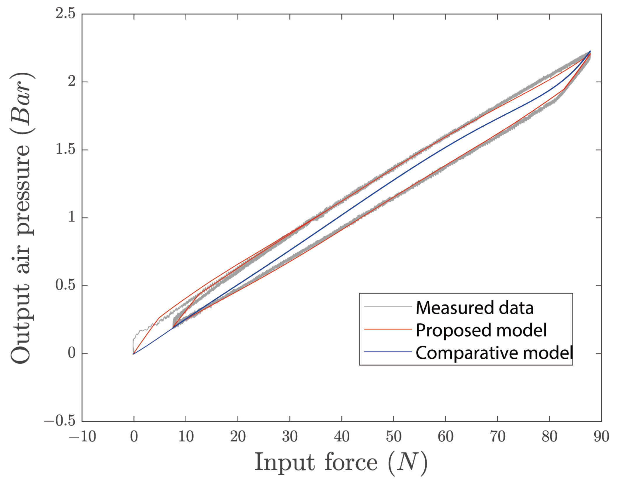
Figure 6 shows the fitting effect of the hysteresis model on the hysteresis loop.
Table 1 demonstrates the calculation results of the evaluation indicators for the proposed model and the comparative model. From
Figure 6, it can be seen that the proposed direct inverse model has a good fitting effect when the inverse hysteresis loop is characterized by the value of the input data being significantly larger than the value of the output data. On the contrary, the comparative direct inverse model [
14] can only generate a curve that hardly has the characteristics of the hysteresis loop, making it difficult to achieve a satisfactory fitting effect. Moreover, it can be inferred from
Table 1 that the fitting effect of the proposed direct inverse model is significantly better than the direct inverse model proposed in [
14].
5.3. Experimental Results
In this subsection, we will conduct static experiments on the experimental testbench shown in
Figure 5 to verify the effectiveness and robustness of the proposed controller. Meanwhile, the PID controller is used as a comparative method.
The PID controller is shown below
,
, and the following
,
are selected as evaluation indicators:
The parameters in system (
4) are identified as
via the system identification toolbox in MATLAB.
(1) Experiment 1: Trajectory tracking validation.
In Experiment 1, the following signal is introduced as a reference signal of the contact force:
In the proposed method, the parameters are designed as
,
,
,
,
,
,
,
,
,
,
. The fuzzy membership function is defined as follows:
In the comparative method, the parameters are designed as .
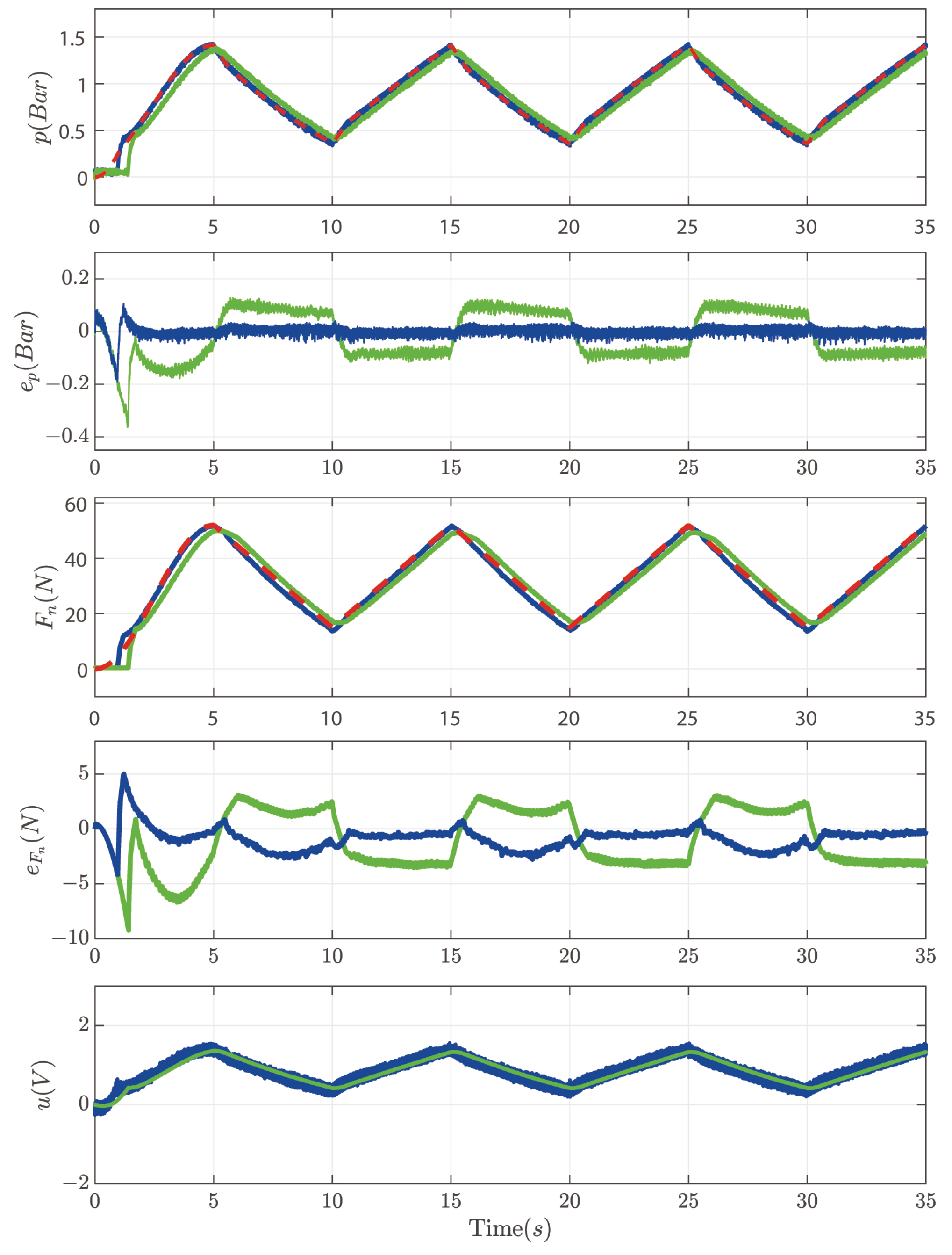
Figure 7 indicates that the proposed method tracks the triangular wave signal of force with a shorter time and higher accuracy. The comparison method is inferior to the proposed method in convergence time and tracking accuracy.
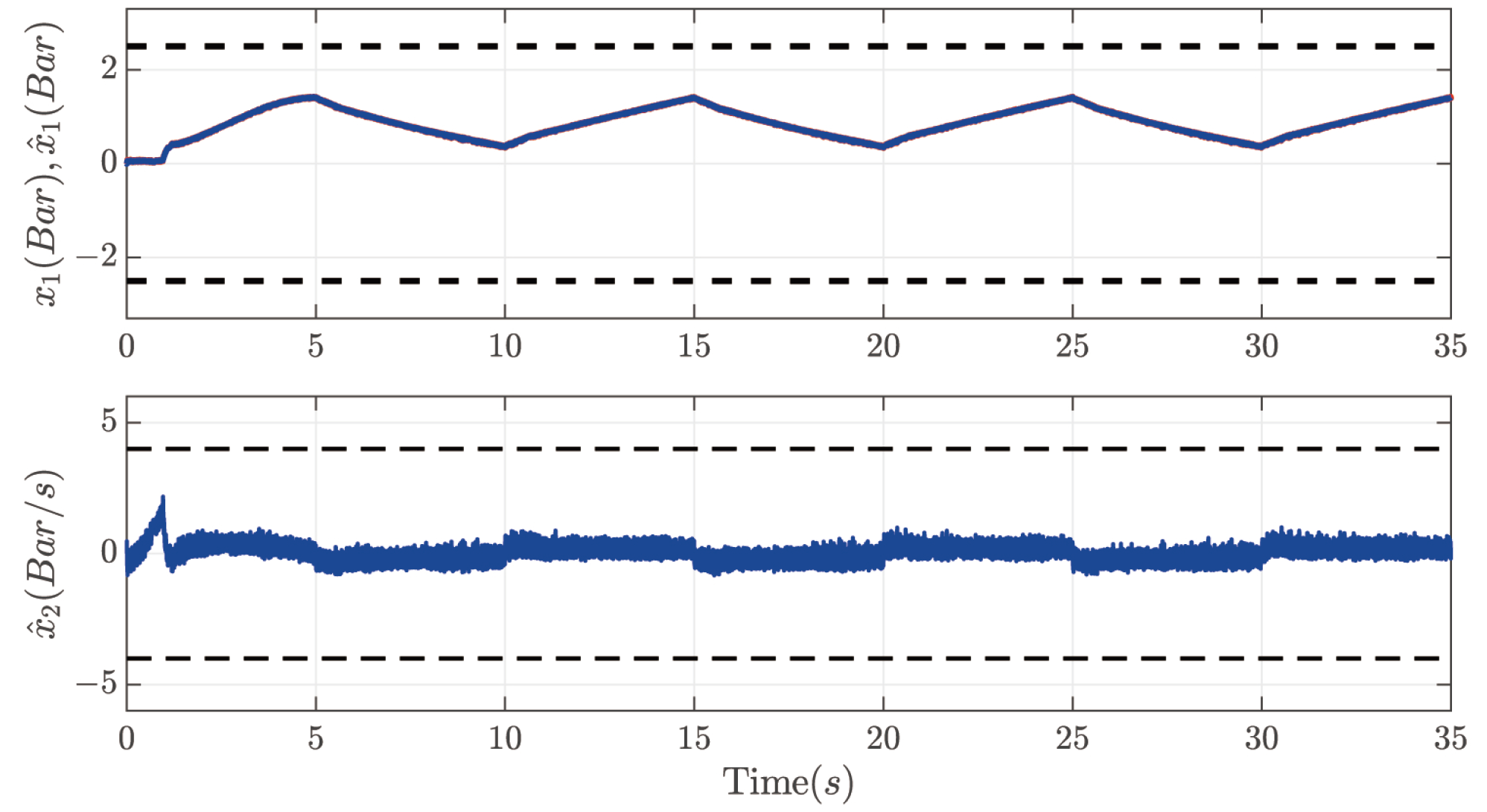
Figure 8 illustrates that the proposed fuzzy ESO has good observation accuracy of the states, and the states of the system operate within safe ranges without violating the state constraints.
Table 2 shows that the
indicator of force control is
, which is much lower than the
of the comparison method. Therefore, from
Figure 7 and
Figure 8, and
Table 2, we can conclude that the proposed method is better than the comparison method in terms of convergence time and tracking accuracy and that the proposed method can make the air pressure and the rate of change of the air pressure operate in a safe range.
(2) Experiment 2: Robustness validation.
In Experiment 2, the following signal is introduced as a reference signal of the contact force
And an input-type disturbance is applied to the system at 15 s.
The parameters in the proposed method are , and the remaining parameters (including the comparative method) are the same as those in Experiment 1.
Figure 9 shows that when tracking the sinusoidal signal of the force, the proposed method can track the reference signal with faster convergence time and higher tracking accuracy, and also when subjected to perturbation, the proposed method is less affected by the perturbation and more robust. On the other hand, the convergence time and tracking accuracy of the comparison method in tracking the sinusoidal signal of force are significantly weaker than those of the proposed method. Also, the comparison method is more affected by the perturbation; when subjected to the perturbation, the barometric pressure and the force both produce particularly large fluctuations. From
Figure 10, it can be seen that even subject to perturbation, the fuzzy ESO of the proposed method still achieves a perfect observation of the states, and neither the barometric pressure nor the rate of change of the barometric pressure exceeds the constraints.
Table 3 shows that when tracking the sinusoidal signal of the force with perturbations, the
indicator of the force control is
, which is significantly better than the comparison method.
6. Discussion and Conclusions
The present study proposes a comprehensive “planning and control” scheme for a CM based on a PAC with hysteresis nonlinearity and full-state constraints. The discussion focuses on highlighting the key contributions of this research, namely, the novel direct inverse model, the successful achievement of full-state constraints, and the development of a fuzzy ESO.
In the planning part, a significant innovation lies in the introduction of a novel direct inverse model capable of handling asymmetric hysteresis loops. This model addresses the limitation of existing hysteresis models based on polynomial forms, such as [
14,
15], which struggle to achieve accurate fitting when the input data values greatly exceed the output data values. The proposed direct inverse model demonstrates a remarkable fitting effect as shown in
Figure 6. In contrast, the comparative direct inverse model [
14] fails to capture the characteristics of the hysteresis loop, resulting in an unsatisfactory fitting effect. The superiority of the proposed direct inverse model is further confirmed by the comparison presented in
Table 1.
Furthermore, the successful implementation of BLFs in the control part enables the achievement of full-state constraints on the air pressure and the rate of change of the air pressure in the CM. The experimental results as depicted in
Figure 7 and
Figure 8 and
Table 2 clearly demonstrate the superior performance of the proposed method in terms of convergence time, tracking accuracy, observation of system states, and adherence to the state constraints. Moreover, the fusion of FLSs and an ESO leads to the development of a fuzzy ESO in the CM. This innovation allows for the observation of unmeasurable states and external disturbances, enhancing system robustness.
Figure 9 and
Figure 10 and
Table 3 demonstrate the superior performance of the proposed method in tracking a sinusoidal force signal with perturbations, exhibiting faster convergence time, higher tracking accuracy, and increased robustness against perturbations.
In conclusion, in this paper, a “planning and control” scheme has been proposed for a CM based on PACs with hysteresis nonlinearity and full-state constraints. In order to obtain more accurate planning of the required air pressure based on the required contact force, a novel direct inverse model has been presented to compensate for the hysteresis nonlinearity in the planning part. In the control part, a fuzzy ESO has been developed by integrating an FLS and an ESO to observe the external disturbances and air pressure change rates. In addition, the challenge posed by full-state constraints in controller design has been overcome by constructing the BLF. It has been proven that all signals of the closed-loop system are bounded, and the tracking error of the air pressure can converge to a small neighborhood of the origin. Finally, the effectiveness and robustness of the proposed scheme have been verified through hardware experiments.


