Abstract
The development of a piezoelectric linear motor is presented in this paper, based on the principle of alternating motion, to meet the acting stroke and accuracy requirements for the probe station’s motion servo system. By partitioning the stator into tangential and normal components, two tangential actuators are affixed to the base, while two normal actuators are fixed on the preloading mechanism, thereby proposing a novel approach for connecting the stator and base. First, the construction and the working principle of the motor were introduced. Subsequently, the motor’s major components were designed through finite element simulation, followed by modeling the motor dynamics and deriving its displacement transfer function. Finally, an experimental prototype was fabricated, and a prototype test system was constructed. The driving method can realize a large stroke operation at a low frequency. The minimum operating frequency of the motor is 1 Hz, the minimum step is 12.55 μm, and the stroke is 105 mm. The study results will promote the development of high-performance probe systems.
1. Introduction
The semiconductor probe station is an essential testing equipment for Integrated Circuit (IC) production, and it directly impacts IC production efficiency, chip quality, processing costs, etc. [1,2]. The common diameter series of wafer ranges from 4 to 12 inches and covers dimensions from 100 to 300 mm, while the welding area diameters of dies on a wafer are less than 10 μm. Consequently, the stroke of the probe station’s motion servo system should be of the order of 100 mm while maintaining an operation accuracy of the order of 10 μm. Currently, electromagnetic actuation, encompassing electromagnetic rotary motor-driven screw drive and direct actuation by electromagnetic linear motors, is widely employed in semiconductor probe stations. The output force and speed of magnetic rotary motors can be adjusted by altering the screw ratio; however, the operation accuracy of this approach is constrained by the accuracy of screw processing and poses challenges for further enhancement [3,4,5]. The direct operation of the electromagnetic linear motor enhances operating efficiency and precision, but the operation is subject to electromagnetic interference, and the heating of the motor coils can decrease operation accuracy [6,7]. Given the increasing diameter of the wafer to be tested and the decreasing pad diameter, achieving a higher level of accuracy in inspection becomes challenging with the probe station’s original operation as chip development progresses [8].
Numerous direct actuation piezoelectric linear motors have been developed by researchers to enhance the operation accuracy of servo systems. The piezoelectric linear motor, characterized by its rapid response, high accuracy, and excellent resistance to electromagnetic interference, serves as an actuator that converts micrometer-amplitude mechanical vibrations generated by exciting an elastomer with a piezoelectric element into linear motion through frictional coupling [9,10]. Currently, it is widely used in the field of precision actuation [11,12,13,14]. Depending on how the elastomer vibrates, piezoelectric linear motors can be classified into resonant [15,16,17] and non-resonant [18,19] types. The resonant piezoelectric linear motor, also known as an ultrasonic linear motor, operates at frequencies greater than 20 kHz. It can be classified into single-mode and multi-mode based on the resonance mode type. For example, Wang Yin et al. [20] developed a longitudinal composite linear resonant piezoelectric linear motor operating at a frequency of 55.4 kHz, while Li Jiayin et al. [21] designed a double bending vibration composite resonant piezoelectric linear motor with an operational frequency of 70.8 kHz. The resonant piezoelectric linear motor exhibits higher speed and thrust force, but its controllability is compromised due to sensitivity to boundary conditions. Moreover, temperature fluctuations can lead to frequency drift during motor operation.
In comparison to resonant types, non-resonant piezoelectric linear motors exhibit enhanced stability at lower frequencies. Combined with the actual working scenario of the probe station, if the working frequency of the motor is too high, the system vibration will be caused, and the test result will be affected. Therefore, it is required that the motor can achieve a large stroke and high precision at a low frequency (1 to 10 Hz). According to whether or not there are fluctuations in the normal contact forces at the frictional coupling interface, non-resonant piezoelectric linear motors can be categorized into stick-slip [22,23,24], inchworm [25,26], and alternating action [27,28]. Stick-slip piezoelectric linear motors exhibit high operational precision and impact force; however, their utilization of sawtooth waves for motor excitation results in inefficient energy consumption, rendering them unsuitable for implementation on the probe station. For instance, Zhang Yangkun et al. [29] proposed a stick-slip-type piezoelectric linear motor operating at a frequency of 3500 Hz and driven by an 80 V sawtooth wave excitation signal based on the triangular coupling theory. Huang Weiqing et al. [30] developed a lever-based stick-slip-type piezoelectric linear motor operating at a frequency of 150 Hz and driven by a 150 V sawtooth wave excitation signal. Inchworm-type piezoelectric linear motors can reduce step distances and have high operational accuracy, but they are not suitable for probe tables because they put more demands on the guide rail’s parallelism, so they typically have a shorter stroke. For example, Dong Jiahang et al. [31] proposed an inchworm-type piezoelectric linear motor with an effective stroke of 11 mm, and Cheng Yang et al. [32] proposed an inchworm-type piezoelectric linear motor with an effective stroke of 20 mm.
Different from the stick-slip-type and the inchworm-type linear motors, alternating-acting piezoelectric linear motors reduce the unnecessary work produced by friction during fluctuations in the normal force on the contact surface, which can improve the service life of the motor. Meanwhile, the contact surface is consistently engaged in a relative sliding, thereby ensuring enhanced operational stability and minimizing the occurrence of unnecessary work due to sliding friction. For instance, Wen Jianming et al. [33] proposed an alternating-action piezoelectric linear motor based on the parasitic motion of a flexible mechanism, with a speed of 39.78 μm/s under the signal excitation of 100 V and 20 Hz. Li Jianping et al. [34] developed a bionic alternating-action piezoelectric linear motor based on walrus motion, with a maximum step distance of 19.5 μm under the signal excitation of 120 V and 1 Hz. The stator of the aforementioned alternating-acting piezoelectric linear motors is secured in place by a clamping mechanism, and due to its substantial mass, it imposes limitations on both the motor’s stroke and operating frequency.
On the basis of a previous work [32], in order to further enhance the motor’s actuation stroke and operating frequency so that it can better meet the requirements of the probe station’s motion servo system, this paper developed a piezoelectric linear motor based on the alternating motion principle. By improving the connection between the stator and the base, a division is implemented in the stator into normal and tangential sections, with the separate fixation of tangential and normal actuators. This enables the motor to operate with a large stroke at a low frequency. In Section 2, the construction and the working principle of the motor were introduced. In Section 3, the major components of the motor were designed through finite element simulation, the dynamics of the motor was modeled, and its displacement transfer function was derived. In Section 4, an experimental prototype was fabricated, and the prototype test system was constructed.
2. Structure and Working Principle
2.1. Structure of Motor
As shown in Figure 1, the proposed alternating-action piezoelectric linear motor consists of two driver components, a preloading mechanism, a mover, and a base. The two driver components are composed of four piezoelectric actuators and their respective connections. Normal displacement is provided by piezoelectric actuators 1 and 3, while tangential displacement is provided by piezoelectric actuators 2 and 4. The normal direction is perpendicular to the mover slide direction, while the tangential direction is parallel to the mover slide direction. Among them, two tangential actuators are fixed directly on the base, and two normal actuators are fixed on the preloading mechanism. The separation of the tangential actuators offer two advantages: first, it enhances the rigidity along the operating direction; second, it expands the normal frequency response bandwidth by reducing the stator’s inertia. The structure of a shared foundation is crucial for achieving alternating motion. The key to achieving alternating motor operation lies in the fixation of two normal actuators on the preloading mechanism. A THK linear guide (VRU3105, 105 × 60 × 28) is utilized for the mover, the mover is fixed to the base, and the linear movement of the mover is realized by alternating between two driver components. In order to avoid the direct wear of the actuator, an alumina ceramic is pasted on the side of the mover.
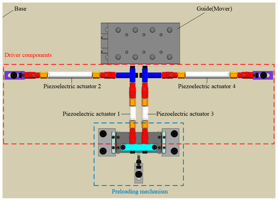
Figure 1.
The structure of the motor.
As shown in Figure 2, the motor’s preloading mechanism consists of connecting plates, crossed rollers, an L-shaped bracket, and a spring. The preloading mechanism enables the application of the preload to the motor, ensuring contact with the mover in its unexcited state.
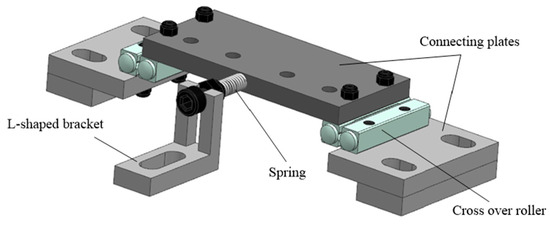
Figure 2.
The preload mechanism.
2.2. Working Principle
The initial state of the motor without the excitation signal is depicted in Figure 3a, where two driving feet are in contact with the mover under the preload provided by the preloading mechanism. As shown in Figure 3b, the motor can operate alternatively when the excitation signal is applied to the four piezoelectric actuators. In addition, to prevent the piezoelectric actuators from being broken by the excitation signal, all applied electrical signals must be biased positively.
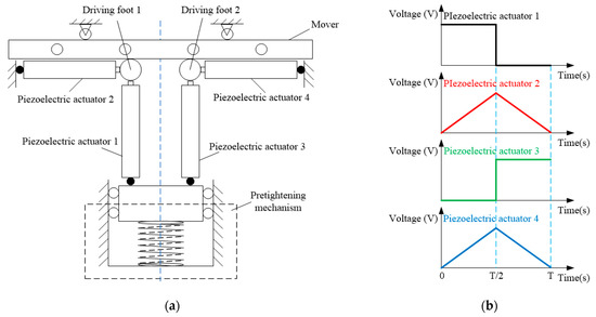
Figure 3.
(a) The initial state of the motor; (b) the excitation signal.
As shown in Figure 4A, there are four typical operational states for the motor during an operation cycle. It is specified that the motor is in forward operation when the excitation signal shown in Figure 3b is applied. Taking forward operation of the motor as an example, the four states of the motor are analyzed.
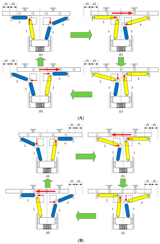
Figure 4.
The driving process of the motor. (Red arrows donate the motion directions and green arrows stand for the alternation of working state. Yellow and blue colors respectively stand for elongation and contraction state piezoelectric actuators.) (A) Forward operation. (B) Reverse operation.
State a: The motor starts from the initial state shown in Figure 3a. Piezoelectric actuator 1 is driven by a high-level square wave excitation signal, while piezoelectric actuators 2, 3, and 4 are driven by a low-level signal. Meanwhile, piezoelectric actuator 1 extends and applies pressure on driving foot 1 against the mover, while piezoelectric actuators 2, 3, and 4 are inactive and driving foot 2 is not in touch with the mover.
State b: Piezoelectric actuator 1 maintains a high level of the square wave, piezoelectric actuators 2 and 4 are positioned at the rising edge of the triangle wave, and piezoelectric actuator 3 is positioned at a low level of the square wave. Meanwhile, piezoelectric actuator 1 remains extended to exert pressure on driving foot 1 against the mover, while piezoelectric actuator 2 initiates extension and propels the mover one step towards the right. At this time, piezoelectric actuator 3 is inactive, piezoelectric actuator 4 begins to extend, and driving foot 2 is not in contact with the mover for future actuation storage.
State c: Piezoelectric actuator 1 is positioned at a low level of the square wave, piezoelectric actuators 2 and 4 are positioned at the peak of the triangle wave, and piezoelectric actuator 3 is positioned at a high level of the square wave. Meanwhile, piezoelectric actuator 1 contracts so that driving foot 1 is no longer in touch with the mover, while piezoelectric actuators 2 and 4 extend to their maximum deformation. Additionally, piezoelectric actuator 3 extends and applies pressure on driving foot 2 against the mover.
State d: Piezoelectric actuator 1 is maintained at a low level of the square wave, piezoelectric actuators 2 and 4 are positioned at the falling edge of the triangle wave, and piezoelectric actuator 3 is positioned at a high level of the square wave. Meanwhile, piezoelectric actuator 1 remains contracted so that driving foot 1 is no longer in contact with the mover, while piezoelectric actuator 2 initiates contraction. At this time, piezoelectric actuator 3 remains extended to exert pressure on driving foot 2 against the mover, while piezoelectric actuator 4 initiates contraction and causes the mover to advance one more step towards the right, thereby releasing the stored action of piezoelectric actuator 4 in state b.
As shown in Figure 4B, when the excitation signals of piezoelectric actuator 1 and 3 are exchanged, their actuation timing can be changed to realize the reverse operation of the motor. The motor will sequentially transition through states a, b, c, and d according to the alternating action of the two driver components to achieve the linear motion of the mover.
3. Design and Analysis
In this study, the driver components of the motor were designed through finite element numerical simulations, while the dynamics and transfer function of the motor were respectively modeled and determined.
3.1. Mechanism Design and Static Analysis
The driver component plays a crucial role in the proposed alternating-acting piezoelectric linear motor. The two drive components are symmetrical from left to right, with the left drive component serving as an example. As shown in Figure 5, the driver component is composed of piezoelectric actuator 1, which provides normal displacement; piezoelectric actuator 2, which provides tangential displacement; a driving foot; four flexible connectors; four stiff connectors; and two vertical connectors. The front and back ends of the piezoelectric actuator are connected to a flexible connector and a stiff connector, respectively. The two piezoelectric actuators are connected vertically by two vertical connectors and a bolt, and the driving foot is fixed on the vertical connector perpendicular to the action direction of the mover.
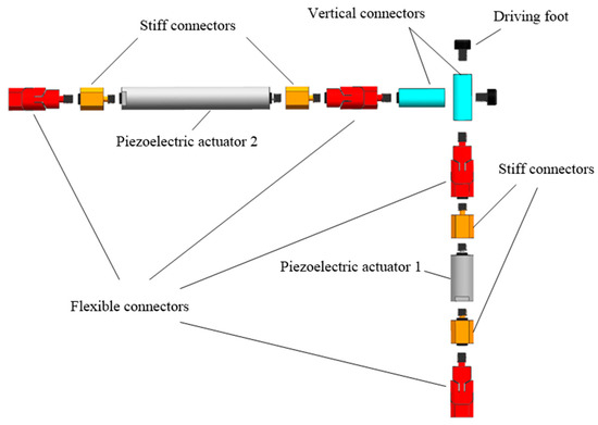
Figure 5.
The design of the driver component.
The stiff connector has an external thread on the front tab and a threaded hole at the back. As illustrated in Figure 6a, the flexible connector is equipped with two flexure hinges that are mutually perpendicular, and the design requires that the shear forces generated by the motor action are balanced by the deformation of the flexure hinges. The vertical connector features threaded holes and is perpendicular through the hole vertically where the two piezoelectric actuators are fastened. The driving foot is made of heat-treated alloy steel, which is directly in contact with the alumina ceramic on one side of the mover when the motor is operated.
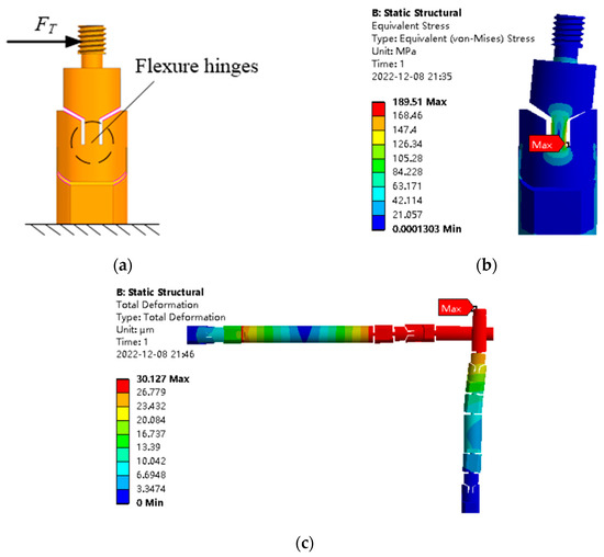
Figure 6.
(a) The force analysis; (b) the stress nephogram; (c) the deformation nephogram.
Following the motor’s working principle, the flexible connections should have a high axial stiffness and a low transverse stiffness. To accomplish this, ANSYS 19.2 finite element software was utilized in this study to perform a static analysis of the driver components. As illustrated in Figure 6a, the strain on the flexible connector is simulated when a 100 N shear force is applied to it. Figure 6b shows the simulation results. It can be seen that the maximum stress is within the yield limit of the design material (steel 1045, yield strength of 355 Mpa); hence, the flexible connector meets the design specifications. Meanwhile, as stated in the piezoelectric actuator manual, the maximal stroke of piezoelectric actuator 1 is 9 μm and that of piezoelectric actuator 2 is 57 μm. Figure 6c illustrates the simulation results when the limit case displacement is applied to the driver component. The maximal displacement is achieved at the actuating foot, which is consistent with the working principle.
3.2. Dynamic Analysis of the Motor
Figure 7 shows the development of a dynamical model of the motor using vibrational models (stiffness, damping, and mass) to further investigate the motor’s kinematic properties, where CP1 represents the damping of piezoelectric actuator 1, KP1 represents the stiffness of piezoelectric actuator 1, MP1 represents the mass of piezoelectric actuator 1, FP1 represents the output force of piezoelectric actuator 1, CP2 represents the damping of piezoelectric actuator 2, KP2 represents the stiffness of piezoelectric actuator 2, MP2 represents the mass of piezoelectric actuator 2, and MD denotes the mass of the preloading mechanism, while Mf denotes the mass of the driving foot and vertical connectors. In addition, X1 represents the vertical displacement of the driver component, X2 represents the horizontal displacement of the driver component, X3 represents the horizontal displacement of the mover, MS denotes the mass of the sliding portion of the mover, FN denotes the normal force exerted on the mover by the driving foot, and Ff denotes the frictional force on the mover.
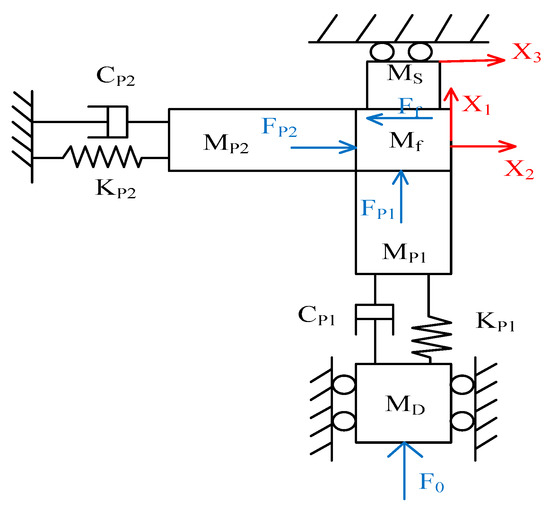
Figure 7.
The dynamical model.
With driving foot 1 always pressing against the mover, the motor is driven from state a to state b, where X1 = 0, and the vibration equations are represented below:
where n1 is the number of piezoelectric ceramic layers in piezoelectric actuator 1, n2 is the number of piezoelectric ceramic layers in piezoelectric actuator 2, and d33 is the piezoelectric coefficient of the piezoelectric ceramics. The Coulomb plus viscous friction model [35,36] can be adopted to calculate the frictional force produced by the driver component, where µc is the Coulomb friction coefficient, µv is the coefficient of viscous friction, and v is the sliding velocity. Under a small deformation, the sliding velocity can be approximately equal to the tangential velocity generated by the driving foot.
After the Laplace transformation, the displacement transfer function of the motor is obtained as follows:
According to Equation (7), the horizontal displacement X2 of the driver component is mainly dependent on the performance parameters of piezoelectric actuator 2, i.e., the higher the voltage U2, the greater the horizontal displacement X2. The negative effect of piezoelectric actuator 1 on X2 is primarily a result of the frictional force. Equation (8) shows that the motor output displacement X3 depends on the excitation signals U1 and U2, the tangential stiffness KP2, the preload F0, and the friction coefficient. To evaluate the effect of these variables on the output performance of the motor, additional experiments need to be conducted.
4. Experiments
4.1. Experimental Test System
The prototype was designed and manufactured, as shown in Figure 8a. Specifically, a piezoelectric actuator of type PSt150/7/7VS12 from Harbin Core Tomorrow (Harbin China) was utilized to supply normal displacement, while a piezoelectric actuator of type PSt150/7/60VS12 was employed to provide a tangential displacement, as shown in Table 1. Additionally, flexible connectors, stiff connectors, and vertical connectors were machined from steel 1045. The experimental test system was constructed, as shown in Figure 8b. The test system was composed of the motor prototype, a signal generator, a power amplifier, and a laser displacement transducer. The signal generator specifically provided an initial signal with adjustable amplitude, frequency, phase, and bias. The power amplifier amplified the initial signal by a factor of 20 to generate the excitation signal for the piezoelectric linear motor. The laser displacement sensor LK-G5001 (KEYENCE Corporation, Osaka, Japan) had an optimal measuring range of 1 mm and a minimum effective resolution of 0.01 μm for measuring the operation of the mover. The whole test system was an open-loop system.
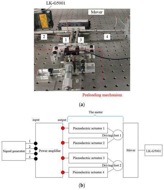
Figure 8.
(a) The motor prototype; (b) the experimental system.

Table 1.
The parameters of the piezoelectric actuator.
4.2. Motor Movement Characteristics
The voltage of the excitation signal influences the step displacement of the motor. The voltage of the excitation signal varies while the frequency of the excitation signal is kept constant at 1 Hz. By using the laser displacement sensor (LK-G5001), the displacement of the mover is collected within two seconds. The experimental results are presented in Figure 9a. Ideally, the displacement curve of the motor should be linear because piezoelectric actuator 1 pushes the mover one step and piezoelectric actuator 2 pushes the mover immediately after. However, displacement peaks emerged due to a potential temporal discrepancy between the motor structure and the excitation signal. The test results of motor accuracy are shown in Figure 9b. The step displacement of the motor increased as the voltage rose from 12.55 μm at 50 V to 35.15 μm at 100 V. Therefore, the voltage will affect the motor stepping accuracy, and theoretically, the lower the voltage, the higher the step precision.
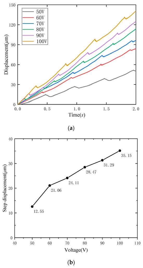
Figure 9.
(a) The effect of voltage on displacement; (b) the step displacement.
By observing the experimental results, it was found that the displacement peak appeared in the displacement curve, which was mainly caused by the structural asymmetry and the phase difference of the excitation signal. On the one hand, processing and assembly errors can lead to incomplete symmetry between the two driving feet. In the case of positive motion, at time T/2 and under ideal conditions, piezoelectric actuator 1 contracted to ensure no contact between driving foot 1 and the mover, while piezoelectric actuator 3 extended to establish contact between driving foot 2 and the mover. The two driving feet operated synchronously, ensuring that there was no backward motion generated by the motor. However, the incomplete symmetry of the structure of the two driving feet led to a desynchronization between them. Specifically, when driving foot 2 experienced hysteresis, it caused driving foot 1 to backtrack along with the mover, resulting in the displacement peak. On the other hand, due to hardware limitations, the 4-phase excitation signals were not fully synchronized and exhibited a certain phase difference, thereby causing a lack of synchronization between the two driving feet and resulting in displacement peaks.
The frequency of the excitation signal affected the operation speed of the motor. To investigate this, the frequency of the excitation signal was changed while the voltage of the excitation signal was kept constant at 100 V. By using the laser displacement sensor (LK-G5001), the displacement of the mover was collected within one second. The experimental results are presented in Figure 10. The motor’s speed was 115.41 μm/s at 2 Hz and 487.70 μm/s at 8 Hz. The speed described here was the average speed, which is the displacement of the motor per second. As the frequency of the excitation signal increases, the operational speed of the motor increases linearly.
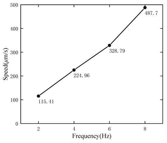
Figure 10.
The effect of frequency on motor operation speed.
By investigating the voltage and frequency of the excitation signal, the formula for the motor operation speed is summarized in Equation (9), where ΔL is the step displacement, N is the number of motor operations per unit of time, and f is the frequency of the excitation signal.
The preload affects the output pull of the motor. To investigate the effect, the voltage and frequency of the excitation signal were kept constant at 100 V and 1 Hz, respectively, and then, the motor output pull was measured by using the pulley while the preload value F0 was changed. The experimental results are illustrated in Figure 11. At a preload of 5 N, the motor can produce a pull of 1.5 N at a speed of 28.28 μm/s; at a preload of 7.5 N, it produces a pull of 2.3 N at a speed of 18.44 μm/s; and at a preload of 10 N, it produces a pull of 3.5 N at a speed of 34.40 μm/s. Within a particular range, raising the preload can increase the output pull of the motor.
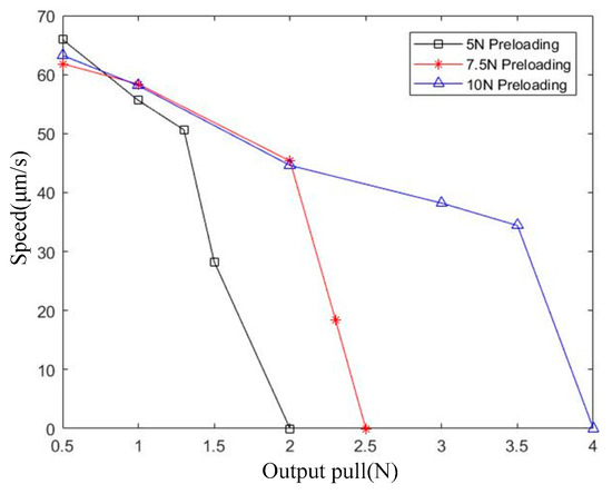
Figure 11.
The effect of the preload on the motor output pull.
4.3. Simulation versus Experiment
The values of the parameters used in the calculation of MATLAB/Simulink 2017b are listed in Table 2. The simulation results and experimental data are presented in Figure 12. The simulation curve can approximate the motor’s operational trend; however, it deviates from the experimental curve due to neglecting torsion in the piezoelectric actuator’s dynamics modeling process and constructing a friction model based on ideal conditions. The displacement of the motor in one second obtained by the MATLAB/Simulink calculation was 65.14 μm, while the result from the experimental test under 100 V and 1 Hz was 69.78 μm, i.e., the error between the simulation and the experimental result was 6.65%, which confirmed the feasibility of the dynamical model of the motor.

Table 2.
The parameter setting used in the MATLAB/Simulink calculation.
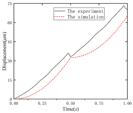
Figure 12.
Comparison of the simulation and experimental results.
5. Conclusions
The present paper proposes a novel stator and base connection mode and designs and fabricates a piezoelectric linear motor with alternating action. The experimental prototype test confirms that the motor stroke is 105 mm and the operational accuracy is 12.55 μm, which basically satisfies the requirements of the acting stroke and accuracy requirements of the probe station’s motion servo system. The load experiment shows that under the condition of preload 10 N excitation signal 100 V and 1 Hz, the motor can pull a 3.5N load at 34.40 μm/s, which basically satisfies the load requirements of the probe station’s motion servo system.
Meanwhile, we verified the feasibility of the motor design and working principle. The error between the simulation and the experimental result is 6.65%, which confirms the validity of the dynamical model of the motor. Overall, the motor exhibits exceptional stroke capabilities coupled with outstanding operation accuracy, which is expected to facilitate the advancement of high-performance probe systems.
In future work, a closed-loop control system is built to compensate the displacement through feedback control. First, the relative sliding time and displacement of the motor are measured, and then, the phase difference of the excitation signal is adjusted to compensate. Taking the forward operation of the motor as an example, at the time of T/2, by adjusting the phase of the excitation signal of piezoelectric actuator 3, piezoelectric actuator 3 is at a high potential in advance so that driving foot 1 changes from the hysteresis state to synchronization and the displacement peak is avoided.
Author Contributions
Writing—original draft, L.H.; Writing—review & editing, Y.W.; software, F.C.; validation, Q.Y.; form alanalysis, W.H. All authors have read and agreed to the published version of the manuscript.
Funding
This research is funded by the Science of Technology Program of Fujian, China (No. 2021I0015 and 2023I0017), National Science Foundation of China (No. 52075108, 52075190, 51505161).
Data Availability Statement
The data that supports the findings of this study are available within the article.
Conflicts of Interest
The authors declare no conflict of interest.
References
- Zuo, Y.; Lin, H.; Guo, J.; Yuan, Y.; He, H.; Li, Y.; Xiao, Y.; Li, X.; Zhu, K.; Wang, T.; et al. Effect of the Pressure Exerted by Probe Station Tips in the Electrical Characteristics of Memristors. Adv. Electron. Mater. 2020, 6, 1901226. [Google Scholar] [CrossRef]
- Li, J.; Liao, H.; Ge, D.; Zhou, C.; Xiao, C.; Tian, Q.; Zhu, W. An Electromechanical Model and Simulation for Test Process of the Wafer Probe. IEEE Trans. Ind. Electron. 2017, 64, 1284–1291. [Google Scholar] [CrossRef]
- Deng, T.; Lan, T.; Tan, M.; Zhu, J.; Wu, J.; Xu, H.; Chen, C.; Adil, Y.; Zhang, S.; Wu, J.; et al. Fast Radial Scanning Probe System on KTX. Plasma Sci. Technol. 2020, 22, 45602. [Google Scholar] [CrossRef]
- Huang, T.; Kang, Y.; Du, S.; Zhang, Q.; Luo, Z.; Tang, Q.; Yang, K. A Survey of Modeling and Control in Ball Screw Feed-Drive System. Int. J. Adv. Manuf. Technol. 2022, 121, 2923–2946. [Google Scholar] [CrossRef]
- Brecher, C.; Eßer, B.; Falker, J.; Kneer, F.; Fey, M. Modelling of Ball Screw Drives Rolling Element Contact Characteristics. CIRP Ann. 2018, 67, 409–412. [Google Scholar] [CrossRef]
- Liu, J.; Cao, J.; Cheng, Z.; Li, L. Study on the Position Estimation Method of Winding Segmented Permanent Magnet Linear Motor. IEEE Access 2022, 10, 51242–51248. [Google Scholar] [CrossRef]
- Eguren, I.; Almandoz, G.; Egea, A.; Ugalde, G.; Escalada, A.J. Linear Machines for Long Stroke Applications—A Review. IEEE Access 2020, 8, 3960–3979. [Google Scholar] [CrossRef]
- McCrory, D.J.; Anders, M.A.; Ryan, J.T.; Shrestha, P.R.; Cheung, K.P.; Lenahan, P.M.; Campbell, J.P. Slow- and Rapid-Scan Frequency-Swept Electrically Detected Magnetic Resonance of MOSFETs with a Non-Resonant Microwave Probe within a Semiconductor Wafer-Probing Station. Rev. Sci. Instrum. 2019, 90, 14708. [Google Scholar] [CrossRef]
- Spanner, K.; Koc, B. Piezoelectric Motors, an Overview. Actuators 2016, 5, 6. [Google Scholar] [CrossRef]
- Li, J.; Huang, H.; Morita, T. Stepping Piezoelectric Actuators with Large Working Stroke for Nano-Positioning Systems: A Review. Sens. Actuators A Phys. 2019, 292, 39–51. [Google Scholar] [CrossRef]
- Shi, Y.; Lou, C.; Zhang, J. Investigation on a Linear Piezoelectric Actuator Based on Stick-Slip/Scan Excitation. Actuators 2021, 10, 39. [Google Scholar] [CrossRef]
- Kiong Tan, K.; Liang, W.; Huang, S.; Pham, L.P.; Chen, S.; Wee Gan, C.; Yee Lim, H. Precision Control of Piezoelectric Ultrasonic Motor for Myringotomy with Tube Insertion. J. Dyn. Syst. Meas. Control. 2015, 137, 064504. [Google Scholar] [CrossRef]
- Delibas, B.; Koç, B. Single Crystal Piezoelectric Motor Operating with Both Inertia and Ultrasonic Resonance Drives. Ultrasonics 2024, 136, 107140. [Google Scholar] [CrossRef]
- Jian, Y.; Yao, Z.; Silberschmidt, V.V. Linear Ultrasonic Motor for Absolute Gravimeter. Ultrasonics 2017, 77, 88–94. [Google Scholar] [CrossRef]
- Ryndzionek, R.; Sienkiewicz, Ł. A Review of Recent Advances in the Single- and Multi-Degree-of-Freedom Ultrasonic Piezoelectric Motors. Ultrasonics 2021, 116, 106471. [Google Scholar] [CrossRef] [PubMed]
- Li, H.; Liu, Y.; Deng, J.; Chen, W.; Li, K. Design Philosophy for Ultrasonic Motors Using the Bending Hybrid Modes. Sens. Actuators A Phys. 2021, 331, 113029. [Google Scholar] [CrossRef]
- Sanikhani, H.; Akbari, J. Design and Analysis of an Elliptical-Shaped Linear Ultrasonic Motor. Sens. Actuators A Phys. 2018, 278, 67–77. [Google Scholar] [CrossRef]
- Wang, L.; Chen, W.; Liu, J.; Deng, J.; Liu, Y. A Review of Recent Studies on Non-Resonant Piezoelectric Actuators. Mech. Syst. Signal Process. 2019, 133, 106254. [Google Scholar] [CrossRef]
- Sun, M.; Huang, W.; Wang, Y.; Lu, Q.; Su, Z. Research on a Novel Non-Resonant Piezoelectric Linear Motor with Lever Amplification Mechanism. Sens. Actuators A Phys. 2017, 261, 302–310. [Google Scholar] [CrossRef]
- Wang, Y.; Chen, Z.; Shi, Y.; Cui, C.; Cheng, F. Longitudinal Composite-Mode Linear Ultrasonic Motor for Motion Servo System of Probe Station. Actuators 2020, 9, 111. [Google Scholar] [CrossRef]
- Li, J.; Wang, Y.; Chen, Z.; Cheng, F.; Yu, Q. A Compact Linear Ultrasonic Motor Composed by Double Flexural Vibrator. Micromachines 2021, 12, 958. [Google Scholar] [CrossRef] [PubMed]
- Cheng, T.; He, M.; Li, H.; Lu, X.; Zhao, H.; Gao, H. A Novel Trapezoid-Type Stick–Slip Piezoelectric Linear Actuator Using Right Circular Flexure Hinge Mechanism. IEEE Trans. Ind. Electron. 2017, 64, 5545–5552. [Google Scholar] [CrossRef]
- He, L.; Chu, Y.; Hao, S.; Zhao, X.; Dong, Y.; Wang, Y. Inertial Piezoelectric Linear Motor Driven by a Single-Phase Harmonic Wave with Automatic Clamping Mechanism. Rev. Sci. Instrum. 2018, 89, 55008. [Google Scholar] [CrossRef]
- Qiao, G.; Li, H.; Lu, X.; Wen, J.; Cheng, T. Piezoelectric Stick-Slip Actuators with Flexure Hinge Mechanisms: A Review. J. Intell. Mater. Syst. Struct. 2022, 33, 1879–1901. [Google Scholar] [CrossRef]
- Ma, X.; Liu, Y.; Deng, J.; Zhang, S.; Liu, J. A Walker-Pusher Inchworm Actuator Driven by Two Piezoelectric Stacks. Mech. Syst. Signal Process. 2022, 169, 108636. [Google Scholar] [CrossRef]
- Wang, L.; Jin, J.; Zhang, H.; Wang, F.; Jiang, Z. Theoretical Analysis and Experimental Investigation on a Novel Self-Moving Linear Piezoelectric Stepping Actuator. Mech. Syst. Signal Process. 2020, 135, 106183. [Google Scholar] [CrossRef]
- Wang, Y.; Yang, C.; Cui, C. Non-Resonant Piezoelectric Linear Motor with Alternating Normal Contact Force. Rev. Sci. Instrum. 2022, 93, 25007. [Google Scholar] [CrossRef]
- Yun, H.; Kong, D.; Aoyagi, M. Development of a Multi-Drive-Mode Piezoelectric Linear Actuator with Parallel-Arrangement Dual Stator. Precis. Eng. 2022, 77, 127–140. [Google Scholar] [CrossRef]
- Zhang, Y.; Peng, Y.; Sun, Z.; Yu, H. A Novel Stick–Slip Piezoelectric Actuator Based on a Triangular Compliant Driving Mechanism. IEEE Trans. Ind. Electron. 2019, 66, 5374–5382. [Google Scholar] [CrossRef]
- Huang, W.; Sun, M. Design, Analysis, and Experiment on a Novel Stick-Slip Piezoelectric Actuator with a Lever Mechanism. Micromachines 2019, 10, 863. [Google Scholar] [CrossRef]
- Dong, H.; Li, T.; Wang, Z.; Ning, Y. Design and Experiment of a Piezoelectric Actuator Based on Inchworm Working Principle. Sens. Actuators A Phys. 2020, 306, 111950. [Google Scholar] [CrossRef]
- Yang, C.; Wang, Y.; Fan, W. Long Stroke Design of Piezoelectric Walking Actuator for Wafer Probe Station. Micromachines 2022, 13, 412. [Google Scholar] [CrossRef] [PubMed]
- Wen, J.; Wan, N.; Wang, R.; Chen, S.; Zheng, J.; Li, J. A Novel Linear Walking Type Piezoelectric Actuator Based on the Parasitic Motion of Flexure Mechanisms. IEEE Access 2019, 7, 25908–25914. [Google Scholar] [CrossRef]
- Li, J.; Cai, J.; Wan, N.; Hu, Y.; Wen, J.; Kan, J.; Chen, S.; Zhao, H. A Novel Bionic Piezoelectric Actuator Based on the Walrus Motion. J. Bionic Eng. 2021, 18, 1117–1125. [Google Scholar] [CrossRef]
- Khalil, H.K. Nonlinear Systems; MacMillan Publishing Company: New York, NY, USA, 1992. [Google Scholar]
- Mathu, A.; Badr, S.R. Dynamic Characteristic of Combined Viscous and Coulomb Damping under Varying Nature of Material and Coefficient of Friction. J. Phys. Conf. Ser. 2020, 1706, 12179. [Google Scholar] [CrossRef]
Disclaimer/Publisher’s Note: The statements, opinions and data contained in all publications are solely those of the individual author(s) and contributor(s) and not of MDPI and/or the editor(s). MDPI and/or the editor(s) disclaim responsibility for any injury to people or property resulting from any ideas, methods, instructions or products referred to in the content. |
© 2024 by the authors. Licensee MDPI, Basel, Switzerland. This article is an open access article distributed under the terms and conditions of the Creative Commons Attribution (CC BY) license (https://creativecommons.org/licenses/by/4.0/).