Abstract
Traditional underwater rigid robots have some shortcomings that limit their applications in the ocean. In contrast, because of their inherent flexibility, soft robots, which have gained popularity recently, offer greater adaptability, efficiency, and safety than rigid robots. Among them, the soft actuator is the core component to power the soft robot. Here, we propose a class of soft electrohydraulic bending actuators suitable for underwater robots, which realize the bending motion of the actuator by squeezing the working liquid with an electric field. The actuator consists of a silicone rubber film, polydimethylsiloxane (PDMS) films, soft electrodes, silicone oils, an acrylic frame, and a soft flipper. When a square wave voltage is applied, the actuator can generate continuous flapping motions. By mimicking Haliclystus auricula, we designed an underwater robot based on six soft electrohydraulic bending actuators and constructed a mechanical model of the robot. Additionally, a high-voltage square wave circuit board was created to achieve the robot’s untethered motions and remote control using a smart phone via WiFi. The test results show that 1 Hz was the robot’s ideal driving frequency, and the maximum horizontal swimming speed of the robot was 7.3 mm/s.
1. Introduction
The ocean is vast, covering about 70% of the earth’s surface area. It contains abundant natural resources, such as biomass, oil, and natural gas, which are all waiting to be developed by humans [1]. In addition, as marine pollution has become more and more serious in recent years, scientists have begun to pay attention to the topic of how to take targeted management of the deteriorating marine environment [2]. Against this background, scientists have set their sights on underwater robots that can perform reliable, safe, and efficient operations underwater. Underwater robots [3,4,5] that can meet the needs of underwater cable pipeline laying, oil and gas field drilling, underwater environment monitoring, and other tasks have become the focus of research. However, the underwater environment of the ocean is of great complexity, including changeable topography, undercurrents, temperature, and other factors, which puts forward high requirements for the research and development of underwater robots.
In recent years, with the continuous development of bionic technology, the research on underwater robots has exploded, and various bionic underwater robots [6,7,8] have been developed. Many marine creatures are used as bionic objects, including tuna, jellyfish, turtles, dolphins, rays, and so on. However, most traditional underwater robots are driven by motors [9,10,11,12], which makes their rigid drive components bulky and lack safety. At the same time, the rigid body can easily harm creatures in the ocean. Additionally, the noise produced by motor-driven underwater robots not only exposes their position but also presents an “unwelcome guest” to species that are already a part of the natural marine environment, potentially contaminating it. In summary, traditional rigid robots have some shortcomings, limiting their underwater applications.
With the rapid development of soft materials and smart materials [13,14,15,16,17], underwater soft robots [18,19,20,21,22] have attracted widespread attention. Soft robots [23,24,25,26] have inherent softness and can produce larger deformations, so they are more adaptable, efficient, and safe. Compared with traditional rigid robots, soft robots are more flexible, effective, and safe because they are inherently soft and capable of producing great deformations. Normally, soft robots are driven by soft actuators [27,28,29,30,31,32], so a series of driving mechanisms has been developed to manufacture soft actuators. Soft fluidic actuators [33,34,35,36] are the most widely used type of actuators in soft robots, including the pneumatic and hydraulic drive methods. The benefits of this kind of actuator include large deformation, great output force, and simple manufacturing. However, it requires an external, bulky, and high-noise rigid pump, which puts a limit on its further development. The method of driving the movement of the actuator by generating gas through a chemical reaction [37,38] has the advantages of small size and high integration. However, its shortcomings of slow actuation frequency and low efficiency lead to the slow swimming speed of the underwater robot. Shape memory alloy [39,40,41] is a kind of smart material that can deform through electrical heating and has a large output force. However, it has a slow actuation frequency, and the temperature is difficult to control accurately, which results in poor swimming performance of underwater robots and difficult-to-manipulate swimming. Ionic polymer-metal composite (IPMC) [42,43,44] is an electroactive polymer material with the advantages of low driving voltage, large deformation, and light weight. However, IPMC is prone to hydrolysis and has slow actuation frequency and low thrust, which leads to slow swimming speed of underwater robots. The dielectric elastomer actuator (DEA) [45,46,47] realizes the deformation of the actuator by squeezing the elastomer through electrostatic force and has the advantages of fast response, high energy density, and light weight. However, it often shows smaller deformations when applied to underwater robots. Light actuation [48,49] can achieve remote control. Light-responsive soft actuators can be made by embedding photosensitive materials in soft bodies or using the photosensitive materials themselves as soft bodies. However, the light it uses for actuation cannot be blocked, so it has limitations. In recent years, a type of actuator called hydraulically amplified self-healing electrostatic (HASEL) actuator [50,51,52,53] has been developed, which combines the advantages of DEA and soft fluidic actuators to achieve high-frequency response, large deformation, and light weight.
Here, we present a class of soft electrohydraulic bending actuators whose fundamental ideas are derived from HASEL actuators. They are made of silicone rubber film, polydimethylsiloxane (PDMS) film, soft electrodes, silicone oil, soft flippers, and acrylic frames. Soft electrodes are used to apply a positive charge, and the surrounding water acts as ground electrodes. Under the action of voltage, the silicone oil in the actuator is pushed into the chamber without electric field and stretches the silicone rubber film and PDMS film of different stiffnesses to achieve the bending of the actuator. Combining the performance requirements of underwater robots and through experiments and simulations, the parameters of the actuator are determined, in which the maximum bending angle can reach 16.7°. Inspired by the swimming method of Haliclystus auricula, we designed an underwater robot based on six soft electrohydraulic bending actuators. We established a mechanical model of the underwater robot, studied and analyzed its force state when it was suspended and swimming in the water, and obtained the mechanical equation that drives the underwater robot to swim, which provides a theory for the swimming tests of the robot. To achieve the untethered movements of the underwater robot, we created a high-voltage square wave circuit board that could actuate soft electrohydraulic bending actuators, which could be remotely controlled through WiFi from smart phone. Powered by a 7.4 V lithium battery, the underwater robot could achieve its untethered motions.
2. Soft Electrohydraulic Bending Actuator
2.1. Actuator Design and Operating Principle
The actuator serves as the propulsion part of the underwater robot and is the core component of the robot. We constructed an actuator model that was appropriate for swimming underwater. The design was essentially composed of two rectangular execution modules that were coupled and measured 50 mm by 32 mm in length and breadth. Figure 1A shows the conceptual model of the actuator. The gray part represents the soft body, which acted as a motion joint that provided the driving force. The white part represents the motion amplification module, which acted as a soft flipper for drainage propulsion. The actuator as a whole constituted the propulsion device of the underwater robot. Figure 1B shows the exploded rendering of the actuator, which mainly included a five-layer structure. The first layer of structure was a 1.1 mm-thick silicone film made by casting, with a hardness of 5 A. The second layer was the black area, which was 36 mm long and 8 mm wide, representing the soft electrodes of the actuator. This area was connected to the drive circuit through wires to form an electric field. For the third layer, there was a 150 μm-thick PDMS film that completely sealed and wrapped the soft electrodes, preventing the liquid in the external environment of the actuator from coming into contact with soft electrodes and avoiding breakdown. In the fourth layer, there was a closed chamber filled with dimethyl silicone oil, with a length of 40 mm and a width of 20 mm. Silicone oil played an important role in the actuator because it was the working fluid that achieves bending during the driving process of the actuator, and it also served as an insulating medium to protect the silicone film at the edge of the electrode from being broken down by the electric field. The last layer of structure was a PDMS film with a thickness of 300 μm, which completely wrapped the silicone oil and prevented the silicone oil from coming into contact with external environmental liquids.

Figure 1.
Soft electrohydraulic bending actuators: (A) structure of the actuator and (B) exploded view of the actuator.
Figure 2 illustrates the main working principle of the actuator, where the soft electrodes acted as the positive electrodes and the surrounding water acted as the ground electrodes. The soft electrodes can rapidly accumulate positive charges when a voltage is provided, creating an electric field with the negatively charged water. The charges at both ends of the positive and negative electrodes are attracted to each other by the electric field force, squeezing the closed chamber filled with silicone oil between them. The silicone oil moves toward the non-electric field chamber under the action of extrusion force due to the incompressible nature of silicone oil, causing the internal pressure in this area to continuously increase and forcing the surface of the chamber to undergo tensile deformation. The upper surface of the electric field free chamber was a 300 μm-thick PDMS film with a hardness of 40 A, and the lower surface was a 1.1 mm-thick silicone rubber film with a hardness of 5 A. Due to the different hardness, the silicone rubber film deforms to a greater extent than the PDMS film under the same tensile force. Therefore, when the actuator is powered on, a deformation will generate from the silicone rubber film to the PDMS film (Figure 2), thereby realizing the bending motion of the actuator. When a direct current voltage is applied, the actuator will remain in the bending deformation. When the voltage is removed, the actuator returns to its original state. In this case, soft electrohydraulic bending actuators can produce continuous flapping motions when a square wave voltage is applied.
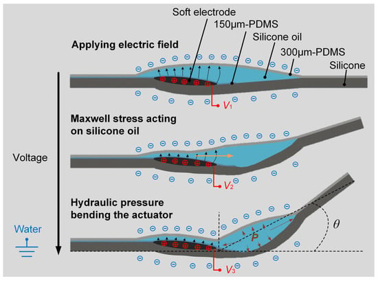
Figure 2.
Illustration of the working principle of the soft electrohydraulic bending actuators. V1, V2, and V3 represent different voltages, where V1 < V2 < V3.
In order to improve the motion performance of underwater robots, we need to maximize the benefits brought by the actuator’s bending angle, that is, by adding a drainage structure similar to a fish fin to increase the overall displacement of the actuator. For this purpose, the 300 μm-thick PDMS film on the upper surface needs to be laterally lengthened and extended to a sufficient length. Half of the film participated in forming the sealed chamber of silicone oil, while the other half of the extended film completely fit an acrylic frame with a width of 5 mm on each side and a thickness of 1 mm after being exerted a certain pre-tension force. The overall structure constituted a soft flipper, as shown in Figure 1A. The PDMS film, acting as a soft flipper, was always in a tensioned state under the pre-tension force and has had dynamic response performance, thereby ensuring that the driving force generated by the actuator could act effectively and promptly. The soft flipper swept a certain area at a given actuator bending angle. Without exceeding the load resistance capacity of the propulsion device, the longer the soft flipper is, the greater the displacement of the actuator during the motion cycle is. This study shows that when the length of the extended PDMS film was half of its total length, the propulsion device had better motion performance and could meet the swimming requirements of the underwater robot.
When the control circuit starts to work, the actuator in the water can be regarded as a capacitive element C, and the water body can be regarded as a resistive element R with a very large resistance value. Therefore, the entire experimental device is equivalent to an RC series circuit. The working condition of the actuator is that the two plates of the capacitor C have a certain potential difference, which generates an electrostatic field and drives the positive and negative charges to attract each other. Hence, as long as the liquid in contact with the underwater robot is not completely insulated and the output voltage of the control circuit reaches the drive threshold, the actuator can work smoothly and realize the underwater propulsion function [19]. It can be proved that tap water, river water, and seawater can all meet the driving conditions.
2.2. Simulations of the Actuator
In order to verify the feasibility of the actuator’s operation, we used Comsol Multiphysics 5.3a to simulate the internal electric field of the actuator and optimized the actuator structure based on the simulation results. The structure of the actuator was simplified to facilitate the establishment of the electric field. We used Comsol to build a simplified model of the corresponding structure and correctly set the materials of each model, including the silicone rubber, PDMS, silicone oil, and electrodes. After applying an electrostatic voltage load of 16 kV to both ends of the model’s electrodes, the grid diagram of the actuator model could be obtained. We used physics-controlled mesh and a finer size to mesh the actuator model. The boundary conditions were that the voltage in the electrode area inside the actuator was set to 16 kV and the outside of the actuator was set to grounding. Figure 3 shows the distribution curves of electric field lines and potential lines obtained after electric field simulation using grid diagrams.
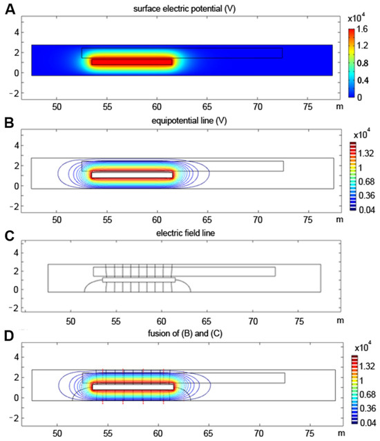
Figure 3.
Simulation of the soft electrohydraulic bending actuators: (A) electric potential of the model surface; (B) equipotential line; (C) electric field line; and (D) superposition of electric field lines and potential lines.
Figure 3C shows that the electric field generated by the actuator model under the action of 16 kV voltage was relatively uniform and concentrated, and the direction of the electric field lines was perpendicular to the surface of soft electrodes and the outer surface of the model. Due to these properties, the silicone oil can flow transversely with good longitudinal extrusion force, which directs the forced deformation of the electric field-free chamber. The simulation results preliminarily verify the feasibility of the actuator design.
From the ring-shaped equipotential lines shown in Figure 3B, it can be seen that the distribution of the electric field lines will have a certain edge effect, and the range of the electric field will be larger than the set width of the ideal soft electrodes. Therefore, in order to prevent other parts from being broken down by high voltage, we considered retracting the overall size of the soft electrodes by 2 mm inward so that the chamber filled with silicone oil can completely cover the soft electrodes. Consequently, silicone oil can insulate and shield the soft electrodes from all directions, preventing damage from electric fields. During the production of the actuator, it should be ensured that the surface of soft electrodes and the outer surface of the actuator are as smooth and flat as possible to avoid charge accumulation at the tip and causing breakdown.
2.3. Materials of the Actuator
When designing an actuator, the materials in different parts, especially the soft materials that participate in deformation, often affect the motion performance of the actuator. Therefore, in order for the underwater robot to swim well, the materials that make up each part of the actuator should be reasonably selected. Section 2.1 introduces the working principle of the actuator, which required us to first take the material’s capacity for elastic deformation into account. Silicone rubber and PDMS are often used in the fabrication of soft robots. Silicone rubber has different Shore hardness, while PDMS typically has a Shore hardness of 40 A. In order to match the deformation of the actuator, we chose silicone rubber with a hardness of 5 A (PS6650-5du and translucency, China Shenzhen Yipin Trading Co. Ltd., Shenzhen, China) and PDMS (BD Film KYN-300, China Hangzhou Bald Advanced Materials Co. Ltd., Hangzhou, China) as the main body material of the actuator. For the selection of working fluid, it is enough to have good insulation ability. Thus, the widely used silicone oil (Dimethylsilicone oil, Aladdin, Shanghai, China) was selected since it is clear, safe, and non-toxic. Conductive hydrogel and black carbon paste are often used to make soft electrodes for soft robots. Compared to conductive hydrogel, which can be used right away, black carbon paste is easier to apply and has the benefit of being lightweight, even if it needs to be sealed due to its fluid qualities. Since soft electrodes of the actuator have been sealed in the chamber, black carbon paste (846-80G, Grease carbon elec conduct 2.8OZ, MG Chemicals, Burlington, Canada) was ultimately selected as the material of them.
2.4. Research and Testing of Parameters
Section 2.1 determines the main dimensional parameters of the actuator, with a total length of 50 mm and a total width of 64 mm. Section 2.3 determines the hardness of the silicone rubber film as Shore 5A. The bending performance of the actuator was affected to varying degrees by many factors, such as the shape of the silicone oil chamber, the amount of silicone oil, the pressure inside the chamber, and the thickness of the silicone rubber film. This section analyzes the two most crucial factors—the silicone rubber film and the amount of silicone oil—and tests the impact of each factor on the bending performance of the actuator under different parameters through experiments, finally obtaining the optimal design parameters of the actuator.
2.4.1. Effect of Silicone Rubber Film Thickness on Actuator Bending Performance
Prior to testing, some molds needed to be made by cutting acrylic sheets, and these molds were used to make five sets of silicone rubber films with thicknesses of 0.8 mm, 0.9 mm, 1.0 mm, 1.1 mm, and 1.2 mm. These silicone rubber films were mounted on the corresponding parts of the actuator in sequence, and the bending deformation test could be carried out after the actuator was connected to an external control circuit. The experiment used LabVIEW2016 to control the circuit and input a continuous step signal (the signal amplitude starts from 0, and the signal amplitude increased by 1 kV every 8 s) into the control circuit to drive it to work. The experimental setup is shown in Figure 4A, in which the actuator was fixed on a special fixture equipped with a protractor in order to obtain its bending angle. After configuring the test environment, we turned on the power switch and ran the control program to test the bending conditions of these five groups of silicone rubber films under different driving voltages. Table 1 shows the test results.
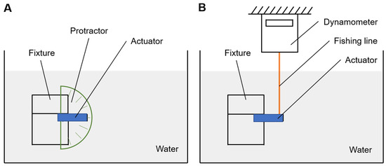
Figure 4.
Schematic diagram of the experimental setup: (A) measuring device of actuator bending angle and (B) measurement device of actuator output force.

Table 1.
Bending angle of silicone rubber films with different thicknesses under different voltages.
The data show that under the same input voltage, the silicone rubber film with a small thickness had a larger bending angle but was also more likely to be broken down. For the silicone rubber film with a thickness of 1.2 mm, the bending angle no longer increased when the input voltage value was greater than 15 kV. This was because the amount of silicone oil in the chamber was limited, and the bending angle had reached a saturated state. Therefore, considering that the selected material needs to have a bending angle as large as possible and a voltage carrying capacity as high as possible, the 1.1 mm-thick silicone rubber film was finally selected to make the actuator.
2.4.2. Effect of Silicone Oil Volume on Actuator Bending Performance
The preliminary test shows that the volume of silicone oil was between 0.7 mL and 0.9 mL when the actuator loaded with a 1.1 mm silicone rubber film reached the maximum bending angle. Similar to the experimental steps described above, this test measured the bending angle of the actuator under different input voltages when the silicone oil volume was 0.7 mL, 0.8 mL, and 0.9 mL. Figure 4B shows the test setup, in which the force-measuring device was an Edberg digital spring dynamometer, which was suspended in a fixed position above the water tank and connected to the point to be measured on the actuator through a fishing line. The fishing line should be kept taut during the test to accurately measure the pulling force generated by the actuator.
After the test was completed, a curve graph was drawn based on the experimental data of each group, as shown in Figure 5. It can be seen that when the volume of silicone oil was 0.8 mL, its bending angle and output force were both better than the other two sets of data. Therefore, in order to make the propulsion effect of the actuator more obvious, the volume of silicone oil was determined to be 0.8 mL.
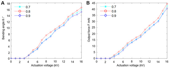
Figure 5.
Graphs for each group (the volume of silicone oil corresponding to green, red, and blue are 0.7 mL, 0.8 mL and 0.9 mL, respectively): (A) relationship between actuator bending angle and actuation voltage and (B) relationship between actuator output force and actuation voltage.
Figure 6 and Video S1 show that when the control circuit input the highest voltage (16 kV) that the actuator could withstand, the actuator could reach its maximum bending angle (16.7°).

Figure 6.
Maximum bending angle of the soft electrohydraulic bending actuators.
2.5. Determination of Parameters
Section 2.4 illustrates the optimal thickness of the silicone rubber film (1.1 mm) and the optimal volume of silicone oil (0.8 mL). After comprehensively considering factors such as production difficulty, test effectiveness, and overall performance of the underwater robot, the main structural parameters of the actuator were finally determined, as shown in Table 2.

Table 2.
Main structural parameters of the soft electrohydraulic bending actuator.
2.6. Fabrication of the Actuator
Section 2.1 shows that the actuator contains a 5-layer structure, which is divided into three films and two closed chambers (soft electrodes chamber and silicone oil chamber). For the fabrication of these two chambers, two sets of special molds need to be designed for pressing. After the chamber is pressed out, a certain amount of silicone oil needs to be injected into the silicone oil chamber through the reserved injection hole. The main fabrication process of the actuator is shown as follows.
2.6.1. The Fabrication Process of 1.1 mm-Thick Silicone Rubber Film
To start with, some molds of silicone rubber film are cut out by a laser cutting machine. Next, fill a beaker with the liquid silicone rubber and curing agent, and use a glass rod to thoroughly whirl to ensure that the two are evenly mixed. Once the mixing is finished, the beaker is placed inside a vacuum box for vacuum extraction. This process uses vacuum to extract air bubbles from the mixture to enhances the quality of the silicone rubber film. After the above steps are completed, use a syringe to take out the mixed liquid and squeeze it along the edge of the mold until the mold groove is filled. After ~3 h at room temperature, a batch of silicone rubber films with smooth surfaces and no gas inside can be obtained.
2.6.2. The Fabrication Process of the Pressing Mold
The pressing molds are divided into soft electrodes chamber pressing molds and silicone oil chamber pressing molds (Figure 7). Each set of molds is divided into upper and lower parts. Their main materials are 3 mm-thick acrylic plates, which are cut into specific shapes by laser. After the cutting is completed, a 4 mm-wide hole needs to be drilled at a specific location in the pressing mold for injecting silicone oil and arranging wires. Each set of molds must accurately correspond to each other during pressing to ensure that the actuator can obtain a good sealing effect.
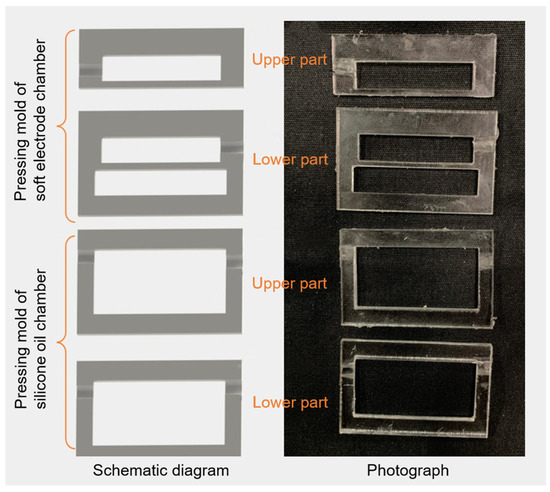
Figure 7.
Schematic diagrams and photographs of pressing molds.
2.6.3. The Fabrication Process of the Soft Electrodes Chamber
Firstly, we cut the 1.1 mm-thick silicone rubber film and the 150 μm-thick PDMS film into a rectangular shape that matched the pressing mold, and then we laid the silicone rubber film flat on the lower part of the pressing mold. Then, we used a syringe to absorb an appropriate amount of black carbon paste, applied it to the center of the corresponding area on the silicone rubber film, and connected one end of the wire to it through the hole. A layer of Sil-Poxy adhesive was then applied to the pressing area on the upper surface of the silicone rubber film. After completing the above work, we covered the upper surface of the silicone rubber film with a 150 μm-thick PDMS film, and then we placed the upper part of the pressing mold at the top. The pressing work could then be carried out. In the first step, we applied appropriate vertical pressure to the whole structure by hand for preliminary pressing. During this process, the black carbon paste should be kept filled in the chamber and not overflow. After the pressing areas were completely bonded, we used a needle to scratch off the extruded adhesive, then pressed a piece of iron on top. After waiting for about 15 min, the fabrication of the soft electrodes chamber could be completed. The entire pressing process is shown in Figure 8. When pressing, attention should always be paid to keeping the upper part of the mold corresponding to the lower part. At the same time, we ensured that there was enough adhesive in the hole where the wire was arranged, and we exhausted the gas in the chamber to achieve a complete sealing effect.
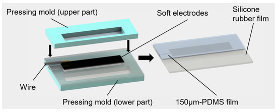
Figure 8.
Fabrication process of soft electrode chamber and soft electrode.
2.6.4. The Fabrication Process of the Silicone Oil Chamber
Figure 9A shows the pressing steps of the silicone oil chamber. After applying the Sil-Poxy adhesive to the target area, we covered it with a 300 μm-thick PDMS layer, following the same steps as for the soft electrodes chamber. We continued to apply pressure until a well-sealed silicone oil chamber was formed. Then, 0.8 mL of silicone oil was injected into the chamber through the reserved hole. After the injection was completed, we made sure that the air in the chamber had been exhausted, and we used adhesive to seal the hole again. After a period of time, we used the adhesive to bond the acrylic frame to the extended part of the top PDMS film, and we continued to apply pressure until the adhesive was completely cured. The process is shown in Figure 9B. The actuator was finished after completing each of the aforementioned steps. The manufactured actuator needs to undergo a certain strength of sealing test and high-voltage test to ensure that the inner chambers of the actuator are fully sealed and can withstand 16 kV voltage before taking part in the underwater robot assembly. Figure 10 shows the photograph of the actuator.

Figure 9.
Fabrication process of silicone oil chamber: (A) pressing of silicone oil chamber; (B) injection of silicone oil.
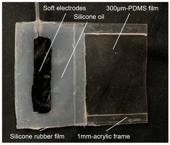
Figure 10.
Photograph of the soft electrohydraulic bending actuator.
3. Untethered Underwater Robot
3.1. Structural Design of the Underwater Robot
Figure 11 shows the model of the underwater robot, of which the main structure refers to the shape of Haliclystus auricula. It can be seen that six actuators were fixed on a regular hexagonal acrylic bracket, one end of which extended upward and was connected to a box containing circuits and a battery. Each part was connected with Sil-Poxy adhesive. For the purpose of reducing the resistance of the robot when it moves in the water, the regular hexagonal acrylic bracket was hollowed out in the middle. The battery box floated on the water while the rest of the robot was submerged, allowing the robot to move horizontally. When the robot is working, six actuators should be kept on a vertical plane to obtain maximum horizontal driving force.
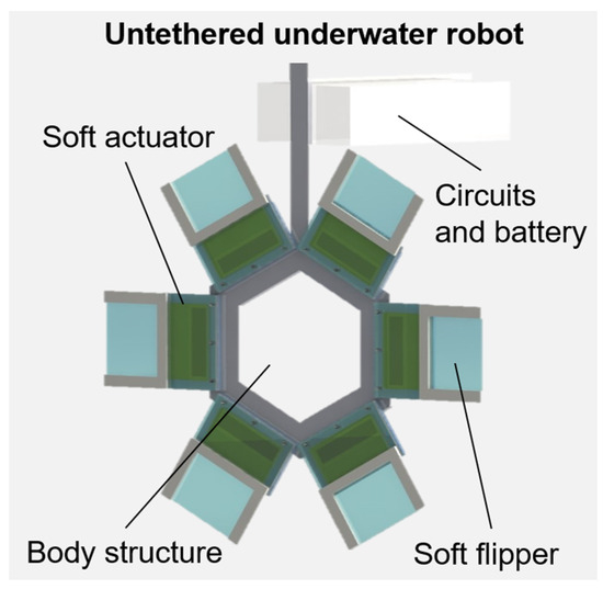
Figure 11.
The model of the underwater robot.
3.2. Force Analysis
To better explore the physical factors that affected the robot’s motion performance, a force analysis was conducted on the robot model, and various parameters were substituted for numerical calculations to verify the feasibility of the model’s underwater motion. The following specifically analyze the force state of the underwater robot when it was suspended and swimming in the water.
3.2.1. Static Force Analysis
Under the static condition, the underwater robot was suspended in the water, and the system was only affected by its own gravity G and the buoyancy Fb generated by the water body, and the overall force was balanced, as shown in Figure 12A. The calculation equation of Fb is as follows:
where ρ is the density of water (1.0 × 10³ kg/m3), and V is the volume immersed in the water. The gravity calculation equation is as follows:
where m is the total mass of the underwater robot, and g is the acceleration of gravity (9.8 m/s2). Gravity and buoyancy are equal in value, and the following results were obtained:
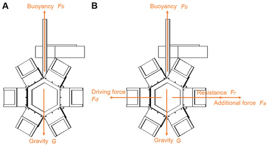
Figure 12.
Force analysis of the underwater robot: (A) static force condition and (B) dynamic force condition.
To achieve force balance, it was necessary to minimize the overall mass of the underwater robot or increase its displacement during design. Therefore, acrylic with lower density (1.2 × 10³ kg/m3) was selected as the bracket material, and a battery box of sufficient volume was designed to increase drainage. The battery box was 53 mm long, 80 mm wide, and 31 mm high. The maximum displacement was calculated to be 131.44 g, while the theoretical total mass of the underwater robot was ~123 g, so the robot could be suspended in the water when stationary. Actually, we could also install a foam board underneath the battery box for increasing buoyancy.
3.2.2. Dynamic Force Analysis
During the movement of the underwater robot, in addition to the longitudinal forces of gravity and buoyancy, it also received transversal forces perpendicular to the surface where actuators were located, mainly including driving force, water resistance, and additional mass force (Figure 12B). Gravity and buoyancy are always balanced, and the driving force needs to be greater than the water resistance and additional mass force to provide acceleration. We assumed that the resultant transversal force on the underwater robot was Fx, the driving force was Fd, the water resistance was Fr, and the additional mass force was Fa; then, the following equation could be obtained:
According to Newton’s second law, the following equation can be obtained:
where u is the instantaneous speed of the underwater robot. The water resistance Fr is determined by the following equation:
where Cd is the drag coefficient, and S is the maximum approach stream area. According to the principle of fluid dynamics, when an underwater robot accelerates, it will generate a force on the fluid around it, causing the surrounding fluid to temporarily follow the robot. This fluid can be equivalent to the additional mass of the robot, and the reaction force it generates on the system is called the additional mass force. The calculation equation of Fa is as follows:
When calculating the driving force Fd, the turning moment generated by the deformation of the silicone oil chamber must be calculated first, and then relevant equations must be used to solve it. Figure 13 shows the simplified physical model of the actuator for ease of calculation. Similar to the movement joints of animals, this model equates the bending action of the actuator to the rotation of a light rod around a fixed fulcrum (regardless of the mass and moment of inertia of the rod). A single actuator is subjected to gravity, buoyancy, water resistance, and pulling force. The deformation of the silicone oil chamber of the actuator produces a pulling force Fc perpendicular to the rod outward, acting on the rod and at a distance s from the fulcrum. Since the maximum bending angle of the actuator is 16.7° (cos16.7° = 0.96), the bending angle has little effect on the value of Fc, which can be regarded as a constant force. Therefore, the actuator is always subjected to a constant turning moment T during the bending process, and its calculation equation is as follows:
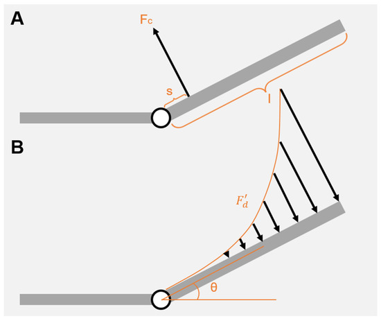
Figure 13.
Actuator physical model: (A) tensile strength of silicone oil chamber and (B) liquid propulsion.
The soft flipper of the actuator corresponds to the rod with length l in Figure 13A. When the underwater robot starts to move, the speed on the rotating rod at a distance x from the fulcrum conforms to the equation:
where θ is the rotation angle. It can be seen from Equation (6) that the value of the water resistance is proportional to the square of the distance x, and its component force along the vertical direction in Figure 13 serves as the driving force of the underwater robot. The resulting equation is as follows:
where S′ is the approach stream area of a single actuator, M is the turning moment generated by , and d is the width of the actuator. Maximal and maximal M are ~0.44 mN and ~4.4 mN·mm, respectively. According to Equation (12), when the angular velocity of the rotating rod is determined, the driving force Fd is proportional to the fourth power of the rod length. Therefore, increasing the length of the actuator (i.e., increasing the displacement) can effectively increase the driving force. When the angular velocity increases until M = T, the above physical model reaches an equilibrium state, and the maximum angular velocity equation of the actuator is obtained:
It can be seen that the maximum angular velocity is negatively correlated with the rod length l. In order for the actuator to respond quickly, l should not be too long. Substituting the expressions of the above physical quantities into Equation (4), we can obtain:
When the underwater robot reaches its maximum speed, its acceleration value equals to zero, and the above equation is simplified as below:
It can be seen that the greater the driving force is, the greater the maximum speed of the underwater robot is. Based on the analysis above, in order for the underwater robot to work well in motion, it is necessary to reasonably design the length of the actuator so that it can not only have sufficient displacement to provide driving force but also respond quickly according to the input signal of the control circuit.
3.3. Swimming Posture Design of the Underwater Robot
The action design of the underwater robot refers to the swimming posture of Haliclystus auricula. We can adjust the waveform (such as amplitude, period, and duty cycle) of the input voltage signal through the control circuit to change the action of the actuator. For being convenient to study, the swimming posture of the underwater robot was divided into the following four parts.
3.3.1. Static Suspension
Before starting, the underwater robot was in a stopped state, and the control circuit did not generate a signal. At this time, no electric field was generated in the silicone oil chamber, so the actuator maintained its original state and the robot remained suspended in the water.
3.3.2. Draining and Propelling
When the signal amplitude output by the control circuit increased from zero to 16 kV, the soft electrodes and the surrounding water generated an electric field. Under the action of the electric field force, the silicone oil was squeezed to the other end of its chamber, driving the actuator to deform and bend. Then, the six actuators distributed symmetrically in a ring began to push away water together, generating driving force to accelerate the underwater robot forward.
3.3.3. Decelerating and Drifting
The input signal amplitude during this process remains 16 kV. When the actuator bended to its maximum angle, the bending degree of the actuator reached a saturated state, and no driving force was generated at this time. Therefore, the underwater robot drifted unpowered under the influence of water resistance, and its speed gradually slowed down during the drift.
3.3.4. Action Recovery
The drifting effect was gone after a period of time. Then, the input signal amplitude was reduced to zero to restore each actuator of the underwater robot to its initial state so that it could perform the next cycle of actions. The speed of the underwater robot gradually dropped to zero under the action of water resistance and finally remained suspended in the water.
3.4. Design of Control Circuit
The control circuit of the underwater robot consisted of a power supply (7.4 V lithium battery), WiFi control circuit, inverter circuit, high-frequency transformer, and voltage-doubling rectifying circuit [18,19,23]. The circuit principle is shown in Figure 14A. The circuit board used a traditional topological flyback circuit structure to achieve voltage boosting. The inverter circuit produced a pulse with a certain pulse width to drive the MOSFET, which formed a flyback topology drive circuit to convert the front-end input DC pulse into a high-frequency square wave pulse. Then, the high-frequency transformer boosted this pulse into a high-voltage, high-frequency square wave pulse. After that, the high-voltage, high-frequency square wave pulse was further boosted through a voltage-doubling rectifying circuit, and this square wave was then rectified and converted into a DC high-voltage signal. Finally, the square wave output was achieved through the WiFi control circuit. The smart phone could adjust the output waveform frequency of the control circuit through WiFi. The adjustable frequency range was 0~8 Hz, and the voltage amplitude was about 16 kV. Figure 14B shows the physical diagram of the circuit that can generate the high-voltage square wave.
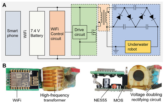
Figure 14.
The composition of the control circuit: (A) the principle of the control circuit and (B) high-voltage circuit board.
The circuit board of the control circuit and the battery were placed together into the battery box, which was 53 mm long, 80 mm wide, and 31 mm high (Section 3.2). The negative output terminal of the circuit board was directly connected to the water through wires, while its high-voltage output terminal was connected to wires in each actuator to provide 16 kV high voltage to soft electrodes. These wires were wrapped with insulating silicone tubes to prevent leakage.
3.5. Production of the Underwater Robot
We made six actuators according to the method in Section 2.6, and then we used a cutting machine to cut acrylic plates of appropriate thickness to make a regular hexagonal bracket and battery box and assembled them according to Section 3.1. Then, referring to Section 3.4, we made a control circuit and fixed it in the battery box. Its high-voltage output terminal was connected to the wires from the six actuators. The control circuit was connected to the mobile phone via WiFi for easy control. At this point, the assembly of the underwater robot was finally completed.
Figure 15 shows the assembled underwater robot. We placed the robot in the water tank to test its structural strength, sealing performance, insulation performance, and levitation ability. Then, we powered it on and observed whether breakdown occurred to determine whether the robot met the experimental standards.
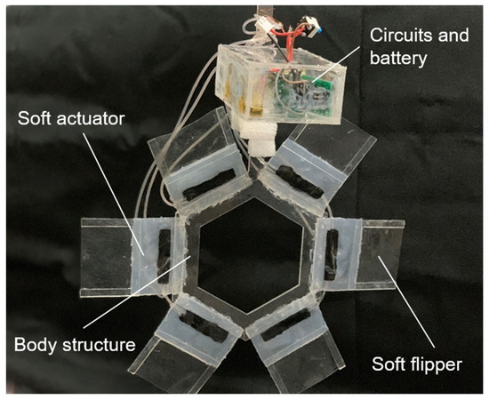
Figure 15.
Photograph of the untethered underwater robot.
3.6. Underwater Robot Test Device
Figure 16 shows the schematic diagram of the test device. One side of the water tank was transparent (called the observation side), the other three sides and the bottom were covered with a layer of black cloth for better photographic observation. In order to accurately calculate the swimming speed of the underwater robot at different times, a sufficiently long ruler was fixed on the outside of the observation side, and its scale was parallel to the movement trajectory of the robot. The camera [54] was placed facing the water tank through the observation side to photograph the underwater robot.
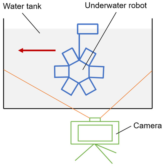
Figure 16.
Swimming setup of the untethered underwater robot.
3.7. Swimming Test of the Underwater Robot
The swimming process of the underwater robot was captured by the camera at a fixed point, and the posture and position of the robot at different moments were obtained, as shown in Figure 17 and Video S1. It can be found that under the excitation of the 16 kV, 1 Hz square wave signal, the motion path of the underwater robot showed a certain deflection. This was due to some deviations in the performance of the six actuators, and the fluxion of the fluid in the environment also caused different forces on the left and right sides of the robot. Through testing, the underwater robot could move relatively stable in a fixed direction. In future versions of the robot, we can control the direction of the robot through a separate drive of the actuator. For example, we can divide the six actuators into two groups, with three on the right side grouped together and three on the left side grouped together in another group. In this way, direction control of the robot can be achieved by one group being powered on and the other group being powered off.
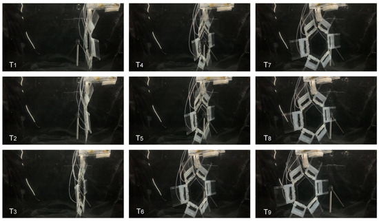
Figure 17.
Swimming state of the underwater robot at different moments in time. T1-T9 represent time series.
The square wave signal frequency in the experiment was 1 Hz, and the underwater robot could move well at this frequency. The smaller the bending amplitude of the actuator was, the slower the speed of the robot was. We used the maximum bending angle of the actuator to drive the robot here. We adjusted the position of circuits and battery and added foam to adjust the buoyancy so as to maintain the robot’s swimming posture. We tested the average swimming speed of the robot at different frequencies, and the results are shown in Figure 18. It can be seen that when the input signal frequency was 1 Hz, the average speed of the underwater robot reached the maximum value (7.3 mm/s). This is because the signal frequency of 1 Hz is closest to the natural frequency of the actuator when moving underwater, which can maximize the displacement of the actuator within a certain period of time. The maximum thrust generated by the robot was ~96 mN.
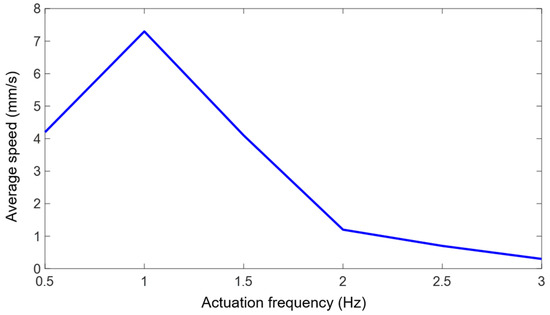
Figure 18.
Plot of input signal frequency versus average robot speed.
4. Conclusions
In this study, we have proposed a class of soft electrohydraulic bending actuators and presented an untethered underwater robot based on these soft actuators. The main contributions of our study are summarized as follows:
- (1)
- We designed a type of soft electrohydraulic bending actuators, mostly consisting of five layers. A 5-A silicone rubber film made up the first layer. In the second layer, there were soft electrodes made of black carbon paste. The third layer fully enclosed the soft electrodes with a 150 μm-thick PDMS film. The fourth layer consisted of a closed chamber filled with dimethyl silicone oil, which was the working liquid that achieved bending during the actuation process. This silicone oil also acted as an insulating medium to protect the silicone film at the edge of the electrode from being broken down by the electric field. The final layer of the construction was a 300 μm-thick PDMS film. Furthermore, we used an acrylic frame and a soft flipper to amplify the actuator’s bending motion. In order to create an electrostatic field and squeeze the silicone oil into motion, which allowed the actuator to bend, the soft electrode served as a positive electrode and the surrounding water as a ground electrode. When a square wave voltage was applied, the soft electrohydraulic bending actuator could generate continuous flapping motions.
- (2)
- Through electric field simulations and experiments, we determined the actuator’s basic parameters. We studied the effects of silicone rubber film thickness and silicone oil volume in the silicone oil chamber on the bending degree and output force of the actuator and obtained that the optimal silicone rubber film thickness was 1.1 mm and the optimal silicone oil volume was 0.8 mL. Combining the results of our research with the experimental data, we found that the highest input voltage for the actuator was 16 kV, and the maximum bending angle of the actuator was 16.7°. After that, we created a mold using a laser cutting machine and paired it with the mold pressing technique to produce an actuator prototype.
- (3)
- We created the primary construction of the underwater robot based on the swimming ways of Haliclystus auricula. This structure consisted of a body frame, six soft electrohydraulic bending actuators, and a box that housed lithium batteries and a control circuit. We constructed a mechanical model of the underwater robot, examined its force state when it was suspended and swimming underwater, obtained the mechanical equation that propelled the robot to swim, and used theoretical deduction to infer the underwater robot’s properties. It was concluded that there existed a positive correlation between the driving force and the maximum speed. When the driving force was stronger, the underwater robot could reach a faster maximum speed. The conclusions drawn from the analytical mechanics model provide a theoretical basis for robot swimming tests.
- (4)
- We designed the swimming action of the underwater robot based on the swimming posture of Haliclystus auricula, which mainly included four parts. In order to realize the untethered motions of the robot, we designed a high-voltage circuit board for driving and controlling the robot, with a built-in 7.4 V lithium battery for power supply. The circuit board could both receive control signals from smart phones to enable remote control and can output high-voltage square wave signals to drive the robot. For testing, we built an underwater robot prototype and fed it signals at various frequencies. The experiment results demonstrate that the horizontal movement speed of the underwater robot could reach its maximum value (7.3 mm/s) when the input signal frequency was 1 Hz. This is because the signal frequency of 1 Hz is closest to the natural frequency of the actuator when moving underwater, which can maximize the displacement of the actuator within a certain period of time.
Supplementary Materials
The following supporting information can be downloaded at: https://www.mdpi.com/article/10.3390/act13060214/s1, Video S1: Soft electrohydraulic bending actuator and untethered underwater robot.
Author Contributions
Conceptualization, W.T. and H.L.; methodology, Y.C.; validation, Y.C. and H.L.; formal analysis, H.L.; investigation, H.L. and Y.C.; data curation, H.L. and Y.C.; writing—original draft, H.L. and Y.C.; writing—review and editing, W.T.; visualization, Y.C., H.L. and W.T.; supervision, W.T.; project administration, W.T. All authors have read and agreed to the published version of the manuscript.
Funding
This work was funded by National Natural Science Foundation of China under Grant no. 52305074 (W.T.), China National Postdoctoral Program for Innovative Talents under Grant no. BX20220267 (W.T.), and the China Postdoctoral Science Foundation under Grant no. 2023M733066 (W.T.).
Data Availability Statement
Data are contained within the article.
Conflicts of Interest
All authors declare no conflicts of interests. Yihui Chen was employed by Guangzhou Metro Design & Research Institute Co., Ltd. and he declares no conflicts of interests.
References
- Zhang, Y.; Li, Y.; Cheng, R.; Shen, S.; Yi, J.; Peng, X.; Ning, C.; Dong, K.; Wang, Z.L. Underwater Monitoring Networks Based on Cable-Structured Triboelectric Nanogenerators. Research 2022, 2022, 9809406. [Google Scholar] [CrossRef]
- Madricardo, F.; Ghezzo, M.; Nesto, N.; Mc Kiver, W.J.; Faussone, G.C.; Fiorin, R.; Riccato, F.; Mackelworth, P.C.; Basta, J.; De Pascalis, F.; et al. How to deal with seafloor marine litter: An overview of the state-of-the-art and future perspectives. Front. Mar. Sci. 2020, 7, 505134. [Google Scholar] [CrossRef]
- Wang, Y.; Chu, H.; Ma, R.; Bai, X.; Cheng, L.; Wang, S.; Tan, M. Learning-Based Discontinuous Path Following Control for a Biomimetic Underwater Vehicle. Research 2024, 7, 0299. [Google Scholar] [CrossRef]
- Panda, J.P.; Mitra, A.; Warrior, H.V. A review on the hydrodynamic characteristics of autonomous underwater vehicles. Proc. Inst. Mech. Eng. Part J. Eng. Marit. Environ. 2021, 235, 15–29. [Google Scholar] [CrossRef]
- Sahoo, A.; Dwivedy, S.K.; Robi, P.S. Advancements in the field of autonomous underwater vehicle. Ocean Eng. 2019, 181, 145–160. [Google Scholar] [CrossRef]
- Fan, R.; Yu, J.; Wang, L.; Xie, G.; Fang, Y.; Hu, Y. Optimized design and implementation of biomimetic robotic dolphin. In Proceedings of the 2005 IEEE International Conference on Robotics and Biomimetics (ROBIO), Hong Kong, China, 5–9 July 2005; pp. 484–489. [Google Scholar]
- Low, K.H.; Chong, C.W. Parametric study of the swimming performance of a fish robot propelled by a flexible caudal fin. Bioinspir. Biomim. 2010, 5, 046002. [Google Scholar] [CrossRef]
- Yao, G.; Liang, J.; Wang, T.; Yang, X.; Shen, Q.; Zhang, Y.; Wu, H.; Tian, W. Development of a Turtle-Like Underwater Vehicle Using Central Pattern Generator. In Proceedings of the 2013 IEEE International Conference on Robotics and Biomimetics (ROBIO), Shenzhen, China, 12–14 December 2013; pp. 44–49. [Google Scholar]
- Liao, L.; Gao, L.; Ngwa, M.; Zhang, D.; Du, J.; Li, B. Adaptive Super-Twisting Sliding Mode Control of Underwater Mechanical Leg with Extended State Observer. Actuators 2023, 12, 373. [Google Scholar] [CrossRef]
- Zhou, C.; Low, K.H. Design and Locomotion Control of a Biomimetic Underwater Vehicle with Fin Propulsion. IEEE-ASME Trans. Mech. 2012, 17, 25–35. [Google Scholar] [CrossRef]
- Li, Z.; Chao, X.; Hameed, I.; Li, J.; Zhao, W.; Jing, X. Biomimetic omnidirectional multi-tail underwater robot. Mech. Syst. Signal Pract. 2022, 173, 109056. [Google Scholar] [CrossRef]
- Yan, S.; Wu, Z.; Wang, J.; Tan, M.; Yu, J. Marine Autonomous Navigation for Biomimetic Underwater Robots Based on Deep Stereo Attention Network. In Proceedings of the 2021 IEEE/RSJ International Conference on Intelligent Robots and Systems (IROS), Prague, Czech Republic, 16 December 2021; pp. 8418–8423. [Google Scholar]
- Zhong, Y.; Tang, W.; Zhang, C.; Jiao, Z.; Wu, D.; Liu, W.; Yang, H.; Zou, J. Programmable thermochromic soft actuators with “two dimensional” bilayer architectures for soft robotics. Nano Energy 2022, 102, 107741. [Google Scholar] [CrossRef]
- Zhong, Y.; Tang, W.; Xu, H.; Qin, K.; Yan, D.; Fan, X.; Qu, Y.; Li, Z.; Jiao, Z.; Yang, H.; et al. Phase-transforming mechanical metamaterials with dynamically controllable shape-locking performance. Natl. Sci. Rev. 2023, 10, nwad192. [Google Scholar] [CrossRef]
- Wu, H.; Chen, Y.; Xu, W.; Xin, C.; Wu, T.; Feng, W.; Yu, H.; Chen, C.; Jiang, S.; Zhang, Y.; et al. High-performance Marangoni hydrogel rotors with asymmetric porosity and drag reduction profile. Nat. Commun. 2023, 14, 20. [Google Scholar] [CrossRef]
- Chen, Y.; Wu, H.; Li, R.; Jiang, S.; Zhou, S.; Cui, Z.; Tao, Y.; Zheng, X.; Zhang, Q.; Li, J.; et al. High-performance liquid metal electromagnetic actuator fabricated by femtosecond laser. Int. J. Extrem. Manuf. 2024, 6, 025503. [Google Scholar] [CrossRef]
- Zhang, L.; Zhao, S.; Zhou, X.; Jing, X.; Zhou, Y.; Wang, Y.; Zhu, Y.; Liu, X.; Zhao, Z.; Zhang, D.; et al. A Magnetic-Driven Multi-motion Robot with Position/Orientation Sensing Capability. Research 2023, 6, 0177. [Google Scholar] [CrossRef]
- Tang, W.; Zhang, C.; Zhong, Y.; Zhu, P.; Hu, Y.; Jiao, Z.; Wei, X.; Lu, G.; Wang, J.; Liang, Y.; et al. Customizing a self-healing soft pump for robot. Nat. Commun. 2021, 12, 2247. [Google Scholar] [CrossRef]
- Tang, W.; Lin, Y.; Zhang, C.; Liang, Y.; Wang, J.; Wang, W.; Ji, C.; Zhou, M.; Yang, H.; Zou, J. Self-contained soft electrofluidic actuators. Sci. Adv. 2021, 7, eabf8080. [Google Scholar] [CrossRef]
- Wang, R.; Zhang, C.; Zhang, Y.; Tan, W.; Chen, W.; Liu, L. Soft Underwater Swimming Robots Based on Artificial Muscle. Adv. Mater. Technol. 2023, 8, 2200962. [Google Scholar] [CrossRef]
- Qu, J.; Xu, Y.; Li, Z.; Yu, Z.; Mao, B.; Wang, Y.; Wang, Z.; Fan, Q.; Qian, X.; Zhang, M.; et al. Recent Advances on Underwater Soft Robots. Adv. Intell. Syst. 2024, 6, 2300299. [Google Scholar] [CrossRef]
- Lee, J.; Yoon, Y.; Park, H.; Choi, J.; Jung, Y.; Ko, S.H.; Yeo, W.-H. Bioinspired Soft Robotic Fish for Wireless Underwater Control of Gliding Locomotion. Adv. Intell. Syst. 2022, 4, 2100271. [Google Scholar] [CrossRef]
- Tang, W.; Zhong, Y.; Xu, H.; Qin, K.; Guo, X.; Hu, Y.; Zhu, P.; Qu, Y.; Yan, D.; Li, Z.; et al. Self-protection soft fluidic robots with rapid large-area self-healing capabilities. Nat. Commun. 2023, 14, 6430. [Google Scholar] [CrossRef]
- Li, T.; Li, G.; Liang, Y.; Cheng, T.; Dai, J.; Yang, X.; Liu, B.; Zeng, Z.; Huang, Z.; Luo, Y.; et al. Fast-moving soft electronic fish. Sci. Adv. 2017, 3, e1602045. [Google Scholar] [CrossRef]
- Ye, Z.; Zheng, L.; He, J.; Lin, J.; Chen, Y.; Yu, H.; Wang, Y.; Zhong, W.; Handschuh-Wang, S.; Niu, S.; et al. Liquid-metal soft electronics coupled with multi-legged robots for targeted delivery in the gastrointestinal tract. Device 2024, 2, 100181. [Google Scholar] [CrossRef]
- Chen, S.; Wang, H.-Z.; Liu, T.-Y.; Liu, J. Liquid Metal Smart Materials toward Soft Robotics. Adv. Intell. Syst. 2023, 5, 2200375. [Google Scholar] [CrossRef]
- Wang, Z.; Zhang, B.; He, Q.; Chen, H.; Wang, J.; Yao, Y.; Zhou, N.; Cui, W. Multimaterial Embedded 3D Printing of Composite Reinforced Soft Actuators. Research 2023, 6, 0122. [Google Scholar] [CrossRef]
- Guo, X.; Tang, W.; Qin, K.; Zhong, Y.; Xu, H.; Qu, Y.; Li, Z.; Sheng, Q.; Gao, Y.; Yang, H.; et al. Powerful UAV manipulation via bioinspired self-adaptive soft self-contained gripper. Sci. Adv. 2024, 10, eadn6642. [Google Scholar] [CrossRef]
- Jung, Y.; Kwon, K.; Lee, J.; Ko, S.H. Untethered soft actuators for soft standalone robotics. Nat. Commun. 2024, 15, 3510. [Google Scholar] [CrossRef]
- Feng, M.; Yang, D.; Ren, L.; Wei, G.; Gu, G. X-crossing pneumatic artificial muscles. Sci. Adv. 2023, 9, eadi7133. [Google Scholar] [CrossRef]
- Liu, Z.; Sun, B.; Hu, J.; Zhang, Y.; Lin, Z.; Liang, Y. Ethanol Phase Change Actuator Based on Thermally Conductive Material for Fast Cycle Actuation. Polymers 2021, 13, 4095. [Google Scholar] [CrossRef]
- Kapłon, T.; Milecki, A. Research on the Use of Silicon-Ethanol Composite in Actuators. Materials 2022, 15, 8570. [Google Scholar] [CrossRef]
- García-Samartín, J.F.; Rieker, A.; Barrientos, A. Design, Manufacturing, and Open-Loop Control of a Soft Pneumatic Arm. Actuators 2024, 13, 36. [Google Scholar] [CrossRef]
- Ridremont, T.; Singh, I.; Bruzek, B.; Jamieson, A.; Gu, Y.; Merzouki, R.; Wijesundara, M.B.J. Pneumatically Actuated Soft Robotic Hand and Wrist Exoskeleton for Motion Assistance in Rehabilitation. Actuators 2024, 13, 180. [Google Scholar] [CrossRef]
- Zou, J.; Feng, M.; Ding, N.; Yan, P.; Xu, H.; Yang, D.; Fang, N.X.; Gu, G.; Zhu, X. Muscle-fiber array inspired, multiple-mode, pneumatic artificial muscles through planar design and one-step rolling fabrication. Natl. Sci. Rev. 2021, 8, nwab048. [Google Scholar] [CrossRef]
- Xie, D.; Su, Y.; Li, X.; Chen, J.; Shi, X.; Liang, D.; Yip, J.; Liu, J.; Li, Z.; Tong, R.K.-Y. Fluid-Driven High-Performance Bionic Artificial Muscle with Adjustable Muscle Architecture. Adv. Intell. Syst. 2023, 5, 2200370. [Google Scholar] [CrossRef]
- Villeda-Hernandez, M.; Baker, B.C.; Romero, C.; Rossiter, J.M.; Faul, C.F.J. Soft alchemy: A comprehensive guide to chemical reactions for pneumatic soft actuation. Soft Sci. 2024, 4, 14. [Google Scholar] [CrossRef]
- Kim, J.; Luo, K.; Suo, Z. A Chemical Pump that Generates High-Pressure Gas by Transmitting Liquid Fuel against Pressure Gradient. Adv. Intell. Syst. 2022, 4, 2100246. [Google Scholar] [CrossRef]
- Wei, Q.; Ke, D.; Sun, Z.; Wu, Z.; Zhou, Y.; Zhang, D. A Structural Design and Motion Characteristics Analysis of an Inchworm-Inspired Soft Robot Based on Shape Memory Alloy Actuation. Actuators 2024, 13, 43. [Google Scholar] [CrossRef]
- Zhuang, P.; Wang, W.; Li, Y.; Han, M. Cyclic behavior of an adaptive seismic isolation system combining a double friction pendulum bearing and shape memory alloy cables. Smart Mater. Struct. 2021, 30, 075003. [Google Scholar]
- Song, S.-H.; Lee, J.-Y.; Rodrigue, H.; Choi, I.-S.; Kang, Y.J.; Ahn, S.-H. 35Hz shape memory alloy actuator with bending-twisting mode. Sci. Rep. 2016, 6, 21118. [Google Scholar] [CrossRef]
- Guo, D.-J.; Liu, R.; Cheng, Y.; Zhang, H.; Zhou, L.-M.; Fang, S.-M.; Elliott, W.H.; Tan, W. Reverse Adhesion of a Gecko-Inspired Synthetic Adhesive Switched by an Ion-Exchange Polymer–Metal Composite Actuator. ACS Appl. Mater. Interfaces 2015, 7, 5480–5487. [Google Scholar] [CrossRef]
- Li, Y.; Jin, R. Novel Ionic Polymer-Metal Composite Employing Sulfonated Polyimide as Ion-Exchange Membrane. Advanced Mater. Res. 2014, 912–914, 251–254. [Google Scholar] [CrossRef]
- Yun, J.S.; Yang, K.S.; Choi, N.-J.; Lee, H.-K.; Moon, S.E.; Kim, D.H. Microvalves Based on Ionic Polymer-Metal Composites for Microfluidic Application. J. Nanosci. Nanotechno. 2011, 11, 5975–5979. [Google Scholar] [CrossRef]
- Medina, H.; Farmer, C.; Liu, I. Dielectric Elastomer-Based Actuators: A Modeling and Control Review for Non-Experts. Actuators 2024, 13, 151. [Google Scholar] [CrossRef]
- Zhao, H.; Hussain, A.M.; Duduta, M.; Vogt, D.M.; Wood, R.J.; Clarke, D.R. Compact Dielectric Elastomer Linear Actuators. Adv. Funct. Mater. 2018, 28, 1804328. [Google Scholar] [CrossRef]
- Moretti, G.; Rosset, S.; Vertechy, R.; Anderson, I.; Fontana, M. A Review of Dielectric Elastomer Generator Systems. Adv. Intell. Syst. 2020, 2, 2000125. [Google Scholar] [CrossRef]
- Huang, C.; Lv, J.; Tian, X.; Wang, Y.; Yu, Y.; Liu, J. Miniaturized Swimming Soft Robot with Complex Movement Actuated and Controlled by Remote Light Signals. Sci. Rep. 2015, 5, 17414. [Google Scholar] [CrossRef]
- Che, S.; Zhang, J.; Mou, F.; Guo, X.; Kauffman, J.E.; Sen, A.; Guan, J. Light-Programmable Assemblies of Isotropic Micromotors. Research 2022, 2022, 9816562. [Google Scholar] [CrossRef]
- Acome, E.; Mitchell, S.K.; Morrissey, T.G.; Emmett, M.B.; Benjamin, C.; King, M.; Radakovitz, M.; Keplinger, C. Hydraulically amplified self-healing electrostatic actuators with muscle-like performance. Science 2018, 359, 61–65. [Google Scholar] [CrossRef]
- Kellaris, N.; Venkata, V.G.; Smith, G.M.; Mitchell, S.K.; Keplinger, C. Peano-HASEL actuators: Muscle-mimetic, electrohydraulic transducers that linearly contract on activation. Sci. Robot. 2018, 3, eaar3276. [Google Scholar] [CrossRef]
- Mitchell, S.K.; Wang, X.; Acome, E.; Martin, T.; Ly, K.; Kellaris, N.; Venkata, V.G.; Keplinger, C. An Easy-to-Implement Toolkit to Create Versatile and High-Performance HASEL Actuators for Untethered Soft Robots. Adv. Sci. 2019, 6, 1900178. [Google Scholar] [CrossRef]
- Kellaris, N.; Rothemund, P.; Zeng, Y.; Mitchell, S.K.; Smith, G.M.; Jayaram, K.; Keplinger, C. Spider-Inspired Electrohydraulic Actuators for Fast, Soft-Actuated Joints. Adv. Sci. 2021, 8, 2100916. [Google Scholar] [CrossRef]
- Shi, X.; Wang, Q.; Wang, C.; Wang, R.; Zheng, L.; Qian, C.; Tang, W. An AI-Based Curling Game System for Winter Olympics. Research 2022, 2022, 9805054. [Google Scholar] [CrossRef]
Disclaimer/Publisher’s Note: The statements, opinions and data contained in all publications are solely those of the individual author(s) and contributor(s) and not of MDPI and/or the editor(s). MDPI and/or the editor(s) disclaim responsibility for any injury to people or property resulting from any ideas, methods, instructions or products referred to in the content. |
© 2024 by the authors. Licensee MDPI, Basel, Switzerland. This article is an open access article distributed under the terms and conditions of the Creative Commons Attribution (CC BY) license (https://creativecommons.org/licenses/by/4.0/).