Article

The Design and Analysis of a Tunnel Retro-Reflective Ring Climbing and Cleaning Robot

1
School of Mechanical and Electrical Engineering, Guilin University of Electronic Technology, Guilin 541004, China
2
School of Information and Communication, Guilin University of Electronic Technology, Guilin 541004, China
*
Author to whom correspondence should be addressed.
Actuators 2024, 13(6), 197; https://doi.org/10.3390/act13060197
Submission received: 22 April 2024 / Revised: 15 May 2024 / Accepted: 20 May 2024 / Published: 22 May 2024
(This article belongs to the Special Issue Advanced Robots: Design, Control and Application—2nd Edition)

Abstract

:
In response to the challenges posed by the difficult cleaning of tunnel retro-reflective rings and the unsuitability of existing climbing robots for ascending tunnel retro-reflective rings, a tunnel retro-reflective ring cleaning robot is proposed. Firstly, based on the analysis of the operational and environmental characteristics and functional requirements inside the tunnel, the design and planning of the robot’s main framework, motion system, cleaning mechanism, and intelligent detection system are conducted to evaluate its walking ability under various working conditions, such as aluminum plate overlaps and rivet protrusions. Subsequently, stability analysis is performed on the robot. The static analysis explored conditions that can make the climbing robot stable, the dynamic analysis obtained the minimum driving torque and finally, verified the stability of the robot through experiments. After that, by changing the material and thickness of the main framework for deformation simulation analysis, the optimal parameters to optimize the design of the main framework are found. Finally, the three factors affecting the cleaning effect of the robot are discussed by the response surface method, and single factor analysis and response surface regression analysis are carried out, respectively. The mathematical regression model of the three factors is established and the best combination of the three factors is found. The cleaning effect is best when the cleaning disc pressure is 5.101 N, the walking wheel motor speed is 36.93 rad/min, and the cleaning disc motor speed is 38.252 rad/min. The development of this machine can provide equipment support for the cleaning of tunnel retro-reflective rings, reducing the requirement of manpower and material resources.

1. Introduction

In recent years, tunnel retro-reflective rings [1], an effective measure to reduce the electricity consumption for tunnel lighting and induce optimal driving effects for motorists, have been widely employed in long and extra-long tunnels. Installed along the contours inside the tunnel, these retro-reflective rings utilize their reflective strips to reflect light received from vehicle headlights, creating a luminous arch-shaped halo within the tunnel, to guide the driver. However, prolonged usage leads to a decrease in the effectiveness of the reflective surface, or even complete loss of reflection, due to the accumulation of dust and fine particles on the retro-reflective ring, necessitating periodic cleaning. Currently, the cleaning process involves lane closures and manual cleaning using lift vehicles, resulting in poor cleaning effectiveness, low efficiency, high costs, and increased safety hazards within the tunnel.
The challenging issue of tunnel retro-reflective rings cleaning has received limited in-depth research and lacks effective solutions. Several methods have been disclosed in Chinese patents, such as the use of a small mobile vehicle equipped with an arc-shaped track matching the outer profile of the tunnel retro-reflective ring. This track features motors and cleaning devices, but requires manual pushing of the vehicle for cleaning, which is highly inconvenient [2]. Additionally, another patent has been disclosed which proposes that climbing and cleaning on the retro-reflective ring can be achieved through an adsorption-based approach [3]; however, the tunnel interior is often wet and slippery, and the intricate walking surface of the retro-reflective ring makes adhesion-based movement difficult.
Therefore, to address the challenge of cleaning the tunnel retro-reflective rings, it is imperative to design a robot capable of climbing on it and performing cleaning tasks. Currently, climbing robots are specifically designed to ascend and move on vertical or nearly vertical surfaces, enabling them to perform specialized tasks. Such robots are commonly employed in various fields, including wind turbine maintenance [4], inspection and repair of steel structures and towers [5], high-altitude operations, inspection [6], and cleaning. Climbing robots necessitate robust adhesion and stability to maintain steadiness during ascension. To fulfill this requirement, they are equipped with appropriate locomotion and adhesion mechanisms tailored to specific working environments [7]. Some climbing robots utilize the principles of foot adhesion, such as Waalbot II, which improves climbing performance by employing natural fiber adhesives [8]. Others mimic lizards, designing claws for adhesion [9,10], while some use suction cup structures for adhesion [11,12]. Some climbing robots employ multiple soft body and foot modules [13] to achieve the function of crossing large gaps, smooth surfaces, and rough terrain. Additional technologies include the use of electromagnetic units [14,15], grippers [16], micro-spines [17], tracks [18], assistance from external devices to aid climbing [19], and so forth. However, these climbing robots seem unsuitable for the cleaning of tunnel retro-reflective rings, as the methods they employ, such as suction cups, micro-spines, adhesives, and electromagnetic units, are not applicable for climbing on tunnel retro-reflective rings. Furthermore, the surface of the retro-reflective ring is relatively smooth, with protrusions or rivets on the back creating obstacles.
This study proposes an innovative solution to achieve efficient cleaning of tunnel retro-reflective rings, reducing the risks associated with manual cleaning and improving cleaning efficiency. As shown in Figure 1, firstly, by leveraging the retro-reflective rings and tunnel environment, a clamping-type wheeled motion mechanism is designed. This mechanism, combined with miniature photoelectric sensors, differential steering principles, and a PID controller, enables the robot to climb steadily. Secondly, a stability analysis of the robot’s movement is conducted to establish stability conditions, facilitating the subsequent construction of a prototype for verification. Subsequently, structural optimization is performed using simulation analysis. Finally, response surface methodology is employed to analyze and determine the optimal combination of three parameters that affect cleaning performance. This robot helps reduce the burden on workers, while promoting the application of robotic control in tunnel retro-reflective ring cleaning.

2. Problem Description and System Design

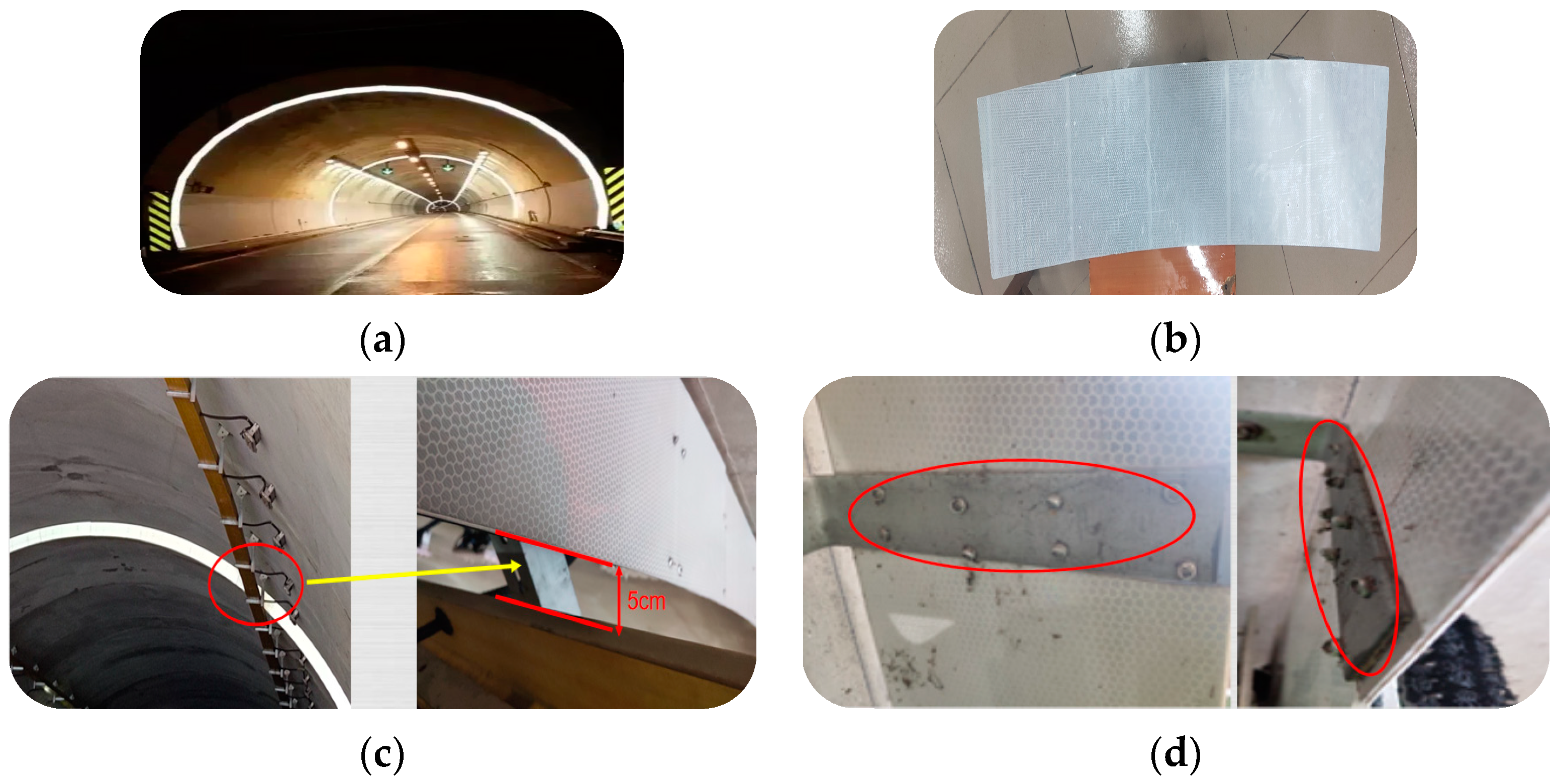
2.1. The Tunnel Retro-Reflective Ring Exhibits Inherent Issues That Merit Attention

The reflective effect of the tunnel retro-reflective ring during normal operation is shown in Figure 2a. Figure 2b illustrates the retro-reflective panel after cleaning. After conducting on-site surveys in the tunnel, it was observed that the tunnel’s arch apex is outfitted with cable trays, leading to a minimal clearance of approximately 5 cm between the side of the tunnel retro-reflective ring and the wire duct, as depicted in Figure 2c. This imposes heightened demands on the design of the climbing robot. To facilitate the climbing robot in traversing this specific location seamlessly, while undertaking the cleaning task for the tunnel retro-reflective ring, it is imperative to ensure the lateral dimensions of the main frame are suitably narrow.
Furthermore, the tunnel retro-reflective ring, assembled from multiple retro-reflective panels, encounters overlap during installation, due to construction nuances, thereby introducing variations in the overall thickness of the retro-reflective ring. To complicate matters, the retro-reflective panels are affixed to the tunnel wall using right-angled aluminum plates, and the juncture between the right-angled aluminum plates and the retro-reflective panels is secured through a multitude of rivets, as illustrated in Figure 2d. Consequently, the thickness of the right-angled aluminum plates and the protrusions from the rivets contribute to an augmented thickness of approximately 2.5–3.5 mm. Thus, it becomes imperative to devise a walking mechanism endowed with shock absorption and obstacle-crossing functionalities to accommodate fluctuations in the thickness of the retro-reflective ring.

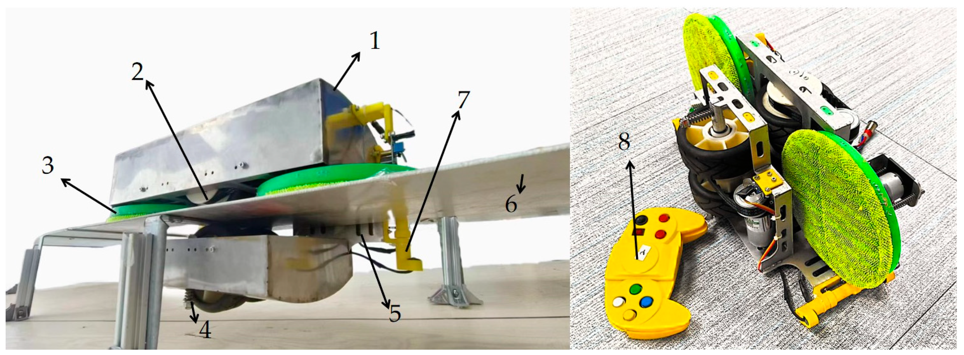
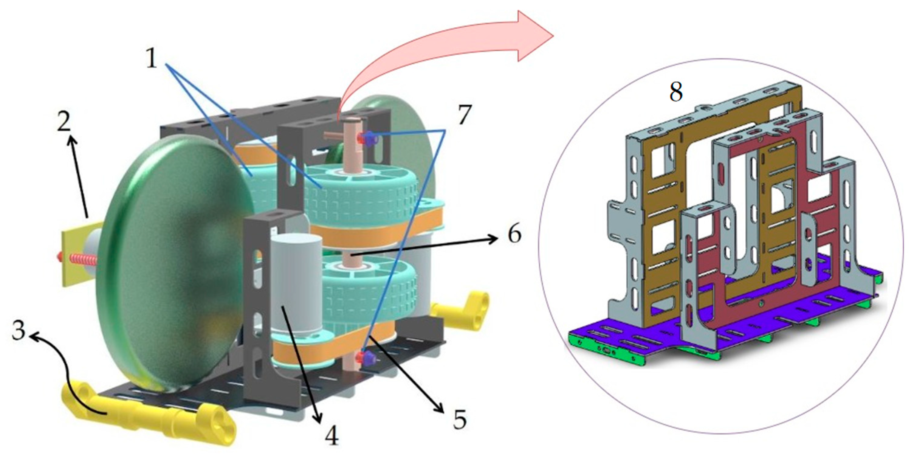
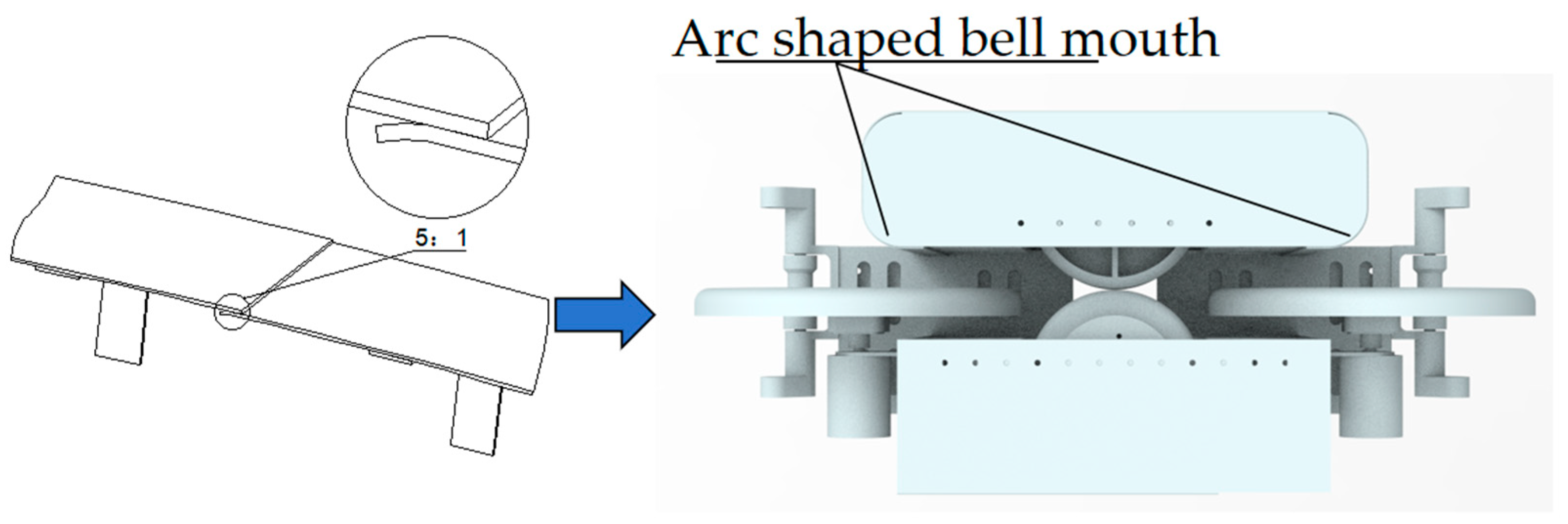
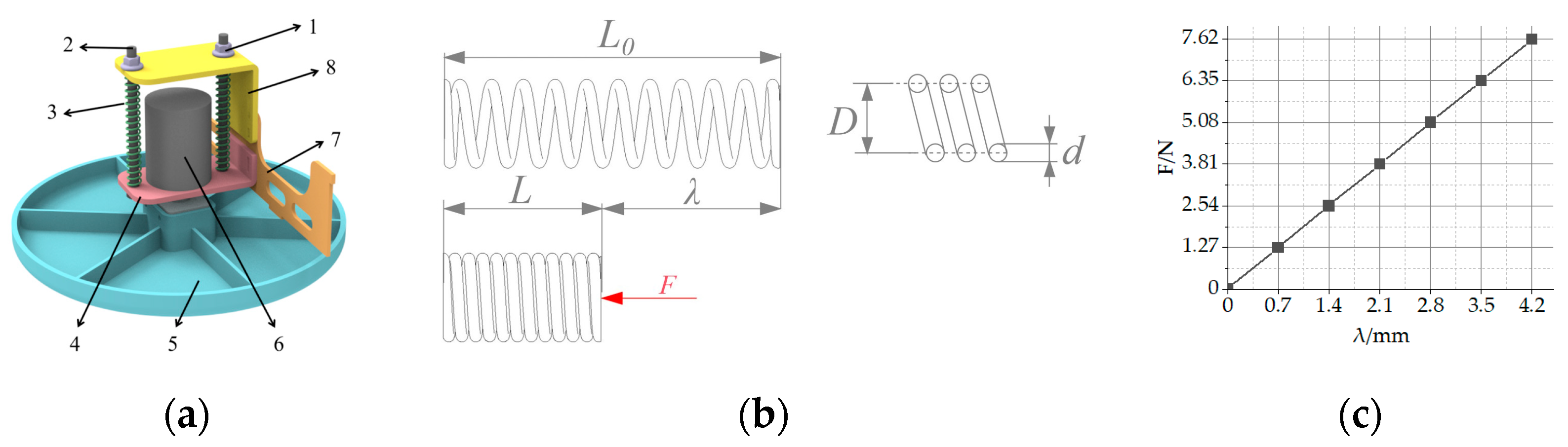
2.2. Mechanical Structure Design

To address the aforementioned issues, a climbing robot was designed for cleaning tunnel retro-reflective rings. The robot integrates mechanical, electronic, and control components into a unified system, as depicted in Figure 3, which shows its internal rendering schematic.
The main body framework of the robot employs a Π-shaped structure, as illustrated in Figure 3, No. 8. The Π-shaped structure consists of two main boards, one sideboard, main board reinforcement ribs, and sideboard reinforcement ribs, all welded with 7075 aluminum alloy. This structure features compactness and high stiffness. The side profile of the Π-shaped frame occupies minimal space, and is narrow and high in strength, thereby smoothly passing through the position between the wire duct and the side of the retro-reflective ring. The 7075 aluminum alloy material has a lower density and higher strength, which is beneficial for making the entire machine lightweight. Additionally, as an aerospace aluminum alloy, it has a certain corrosion resistance, allowing it to be used for extended periods of time in relatively humid tunnel environments.
Due to the retro-reflective ring being securely fixed inside the tunnel by right-angled aluminum plates, and the retro-reflective ring itself being assembled from aluminum plates, it possesses a certain mechanical strength. To ensure stability during operation and prevent damage to the retro-reflective ring during climbing, the robot adopts a clamping-type wheeled movement mechanism. As shown in Figure 3, one main shaft is fixed at one end of the Π-shaped bracket, with a walking wheel installed. At the other end of the Π-shaped bracket, there is an adjustable pressure suspension mechanism, composed of an active main shaft, walking wheel, compression spring, a bolt, and nut, allowing the clamping pressure between the walking wheels to be adjusted by turning the nut. Block-patterned rubber wheels can increase friction with the tunnel retro-reflective ring and ensure smooth passage over the rivets embedded into the grooves on the rubber wheel’s surface while rolling over the retro-reflective ring. This clamping-type wheeled movement structure ensures the stability of the robot’s operation within the tunnel, enabling it to be unaffected by wind speed, and the use of rubber wheels prevents damage to the retro-reflective ring.
Similarly, during the installation process or prolonged use of the tunnel retro-reflective ring, there might be instances where one end of the connection between two retro-reflective panels becomes warped, or the panels do not completely adhere to each other, as shown in Figure 4. In such cases, the bell-mouth-shaped shell can be maneuvered to this location before the walking wheels, allowing the retro-reflective panels to fit together as closely as possible. This helps the transition over the warped sections of the retro-reflective ring, addressing this condition and enhancing the stability of the robot’s climbing. Additionally, the shell is made of 1 mm stainless steel, with the steel plates welded together. This not only contributes to lightweight design, but also protects the internal structure of the robot from external factors within the tunnel.
The cleaning device consists of two brackets, a driving motor, a cleaning disk, compression springs, bolts, and nuts, each set up at both the front and rear. The cleaning disk of the cleaning device is made of soft material, and since the pressure exerted by the cleaning device on the tunnel retro-reflective ring is not particularly high, this ensures that it will not be damaged throughout the entire process.
As shown in Figure 5a, Bracket No. 8 remains consistently connected to the main framework in No. 7, while a portion of Bracket No. 4 is affixed to the motor, with its other end featuring a straight slot. Initially, the compression distance of the springs is adjusted by twisting the nuts, thereby regulating the pressure exerted by the cleaning disc on the tunnel retro-reflective ring. When the pressure is confirmed, the motor is firmly fixed on the main frame using the straight slot at the other side of the No. 4 bracket. This way, while ensuring that the pressure of the cleaning disc on the retro-reflective ring is unchanged, the motor will not be shaken. This approach facilitates subsequent adjustment of pressure parameters, enabling optimization to identify the most suitable pressure.
This type of cleaning mechanism can enhance cleaning effectiveness by setting appropriate pressure and speed, while also improving the stability of the equipment during climbing.
According to Figure 5b, under the action of axial load, the spring produces a deformation amount represented by “λ”. There is a certain relationship between the deformation of the spring and the pressure generated [20].
λ = 8 F D 3 n G d 4
F represents the axial pressure, λ denotes the compression amount, D stands for the mean diameter of the spring, n is the effective number of turns of the spring (here it is 16), d represents the wire diameter of the spring, and G represents the shear modulus of the spring material. The model of the compression spring is 6 mm × 8 mm × 50 mm (inner diameter × outer diameter × length), and it is made of carbon steel, with a G of 8 × 10⁴ MPa. For further analysis, without affecting the results, a slight approximation is made to the second decimal place of the pressure value calculated from the original Hooke coefficient of the spring. The relationship between spring pressure and compression distance is shown in Figure 5c.

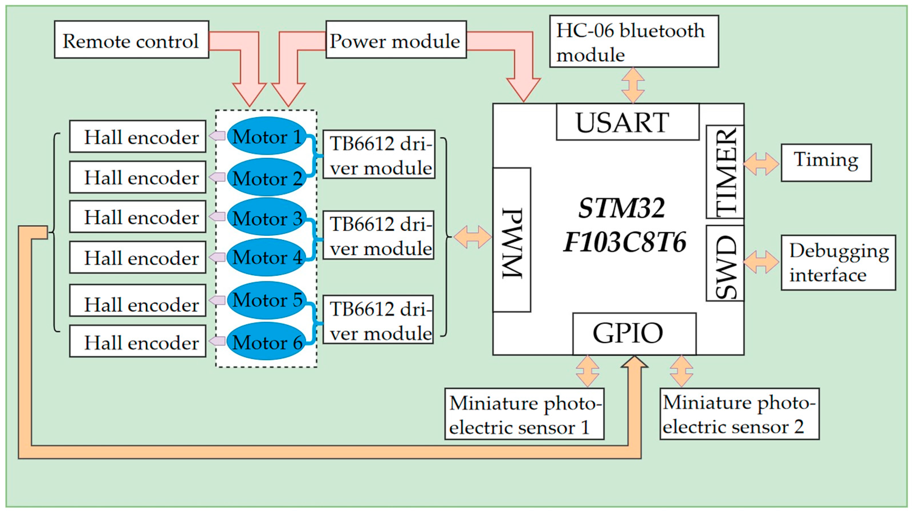
2.3. Hardware Design

The robot uses an STM32F103C8T6 microcontroller as its core controller, forming the microcontroller control circuit. The control system consists of the TB6612 driver module, HC-06 Bluetooth module, and a HM-GM37-3429 encoder reduction motor. Both the robot and the remote control are equipped with HC-06 Bluetooth modules, allowing the robot’s movements to be controlled remotely. The TB6612 driver module drives the motor, while the Hall encoder on the motor provides feedback on the motor speed, which is then stabilized through a PID controller. The hardware control scheme, shown in Figure 6, is stable, operates well, and effectively controls the target.

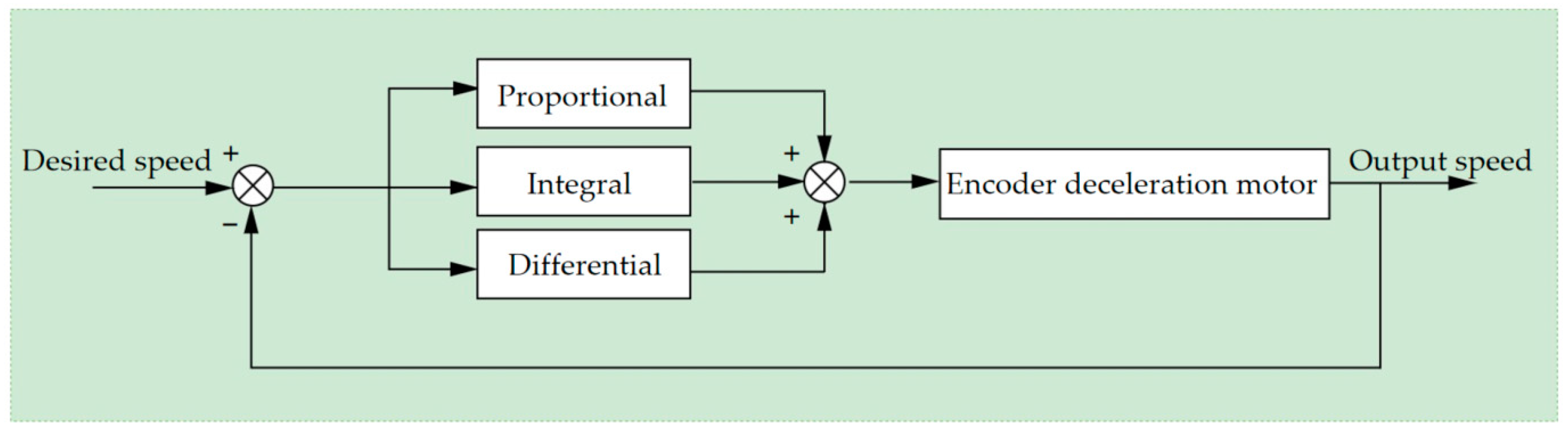
2.4. Microcontroller Programming

The program logic of the microcontroller includes the following processes. Firstly, the microcontroller performs system initialization, which includes clock initialization, GPIO pin definition initialization, serial port initialization, and timer initialization. After initialization, the system waits to receive control commands from the host computer. The Bluetooth module receives the remote control’s commands and forwards them to the microcontroller. The microcontroller then determines the type of control command. If the control command is for movement, the initial desired speed of the movement is set, and the initial PWM value is output to drive the motor.
During timed intervals, the pulses output by the Hall encoder are recorded to calculate the robot’s movement speed. The difference between this movement speed and the desired speed is then calculated, and the PWM output is updated via the PID controller. This process is repeated until the difference between the robot’s movement speed and the desired speed approaches zero. While adjusting the speed using the PID controller, the microcontroller also receives measurement signals from the photoelectric sensor. Based on these signals, it determines whether the robot’s movement has caused the body to deviate from the retro-reflective panel. If the body deviates from the retro-reflective panel, differential control of the robot’s left and right walking wheels is used to correct the body.
The PID control algorithm is based on the error between the robot’s current speed and the desired speed. It adjusts the controller’s output through a combination of proportional, integral, and derivative terms, enabling the error to quickly and stably converge to zero, thereby achieving precise control. Proportional control adjusts the control amount based on the current error; integral control addresses the accumulated effect of the error, helping to eliminate steady-state error; derivative control focuses on the dynamic changes of the error, predicting future error magnitude by identifying the rate of error change, thus allowing for anticipatory adjustments of the control amount. The PID controller ensures the safety and speed of the climbing process. The principle of PID speed control is shown in Figure 7.

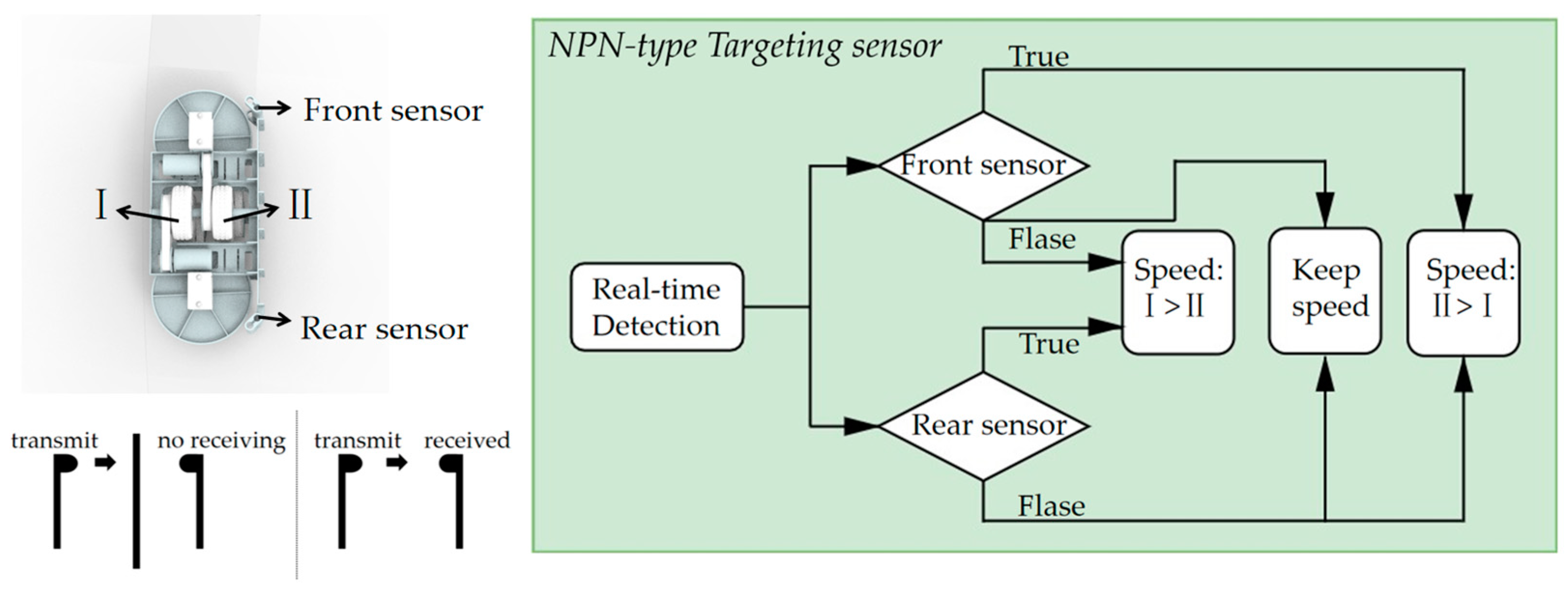
2.5. Control of Miniature Photoelectric Sensor

As the tunnel retro-reflective ring is installed in an arc shape, to prevent the robot from falling off during operation, it must follow the arc of the retro-reflective ring. On the main framework of the robot, pairs of edge detection sensors are installed at the front and rear. Miniature through-beam NPN-type photoelectric switches are chosen for the edge detection sensors. When the infrared beam from one end is received by the other end, the sensor returns a high level; when the infrared beam is blocked by the retro-reflective ring, the sensor returns a low level. Sensors set up at the front and rear can detect whether the robot deviates. Upon deviation, the speed difference between the outer and inner wheels (Ⅰ and Ⅱ) is automatically adjusted to correct the wheel alignment, allowing the robot to move along the arc path of the entire retro-reflective ring. The principle of operation of the miniature through-beam NPN-type photoelectric switches is illustrated in Figure 8.

3. Stability Analysis

A crucial metric for evaluating climbing robots is their stability, indicating their ability to climb or operate steadily on a wall. Specifically, the stability of climbing robots is influenced by contact forms and variations in the center of mass, leading to potential slipping due to gravity or adhesive forces [21]. Therefore, the following section will conduct static and dynamic analysis of the robot.

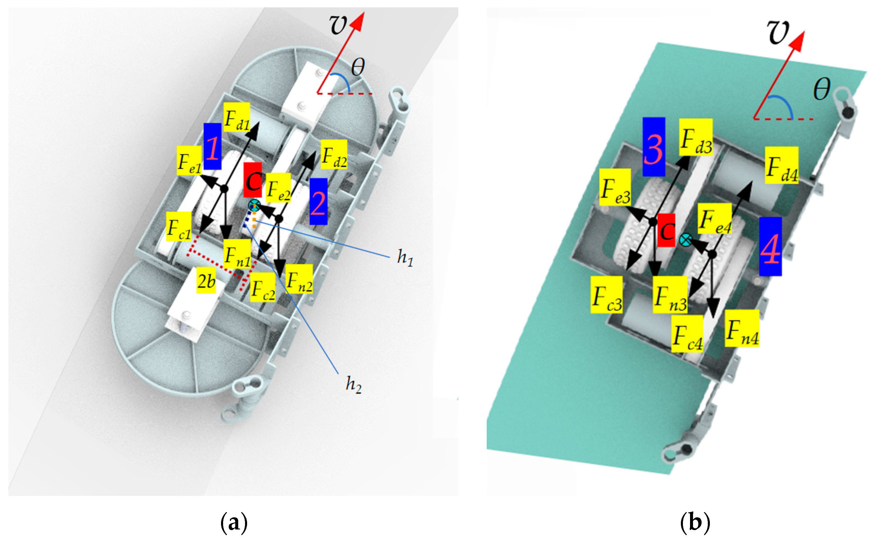
3.1. Static Force Analysis

The tunnel retro-reflective ring is assembled from retro-reflective panels, with a reflective film adhered to the front side, which is smooth. The back side is relatively rough, with aluminum plates overlay and rivet protrusions. Assuming the dynamic friction coefficient on the side with the reflective film is μ1 and the backside is μ2, with μ1 < μ2, a static force analysis of the entire system can be performed, as illustrated in Figure 9.
As shown in Figure 9, Fni (i = 1~4) represents the support force of the retro-reflective panel on each walking wheel, while Fn5 and Fn6 represent the support forces of the retro-reflective panel on the cleaning disks. Fai (i = 1~4) indicates the static frictional force acting on each walking wheel, while Fa5 and Fa6 represent the static frictional forces acting on the cleaning disks. Since the support force on the cleaning disks is negligible, it can be disregarded. Therefore, the simplified mechanical equilibrium equation is as follows:
F x = F n 1 + F n 2 F n 3 F n 4 = 0 F y = F a 1 + F a 2 + F a 3 + F a 4 m g = 0
The sliding friction force is used for analysis instead of the maximum static friction force. For this robot to securely grip the tunnel retro-reflective ring, the overall maximum static friction force should be greater than the gravitational force.
i = 1 4 F a i = μ 1 F n 1 + μ 1 F n 2 + μ 2 F n 3 + μ 2 F n 4 > m g
i = 1 4 F n i > 2 m g μ 1 + μ 2
When Equation (4) is satisfied, the robot will not slide downward.

3.2. Static Moment Analysis

Below is a static moment analysis of the entire machine. As the robot is front-to-back symmetric, but left-to-right asymmetric, and the side responsible for cleaning the tunnel retro-reflective ring is heavier, when it clamps onto the tunnel retro-reflective ring, its center of mass C will shift towards the working surface, a certain distance away from the center of the tunnel retro-reflective ring, as shown in Figure 10.
Where h1 is the vertical distance from the center of mass C to the front of the retro-reflective ring and h2 is the vertical distance from the center of mass C to the back of the retro-reflective ring, l1 is the distance from the center of mass to the gravitational force on the working surface side and l2 is the distance from the center of mass to the gravitational force on the opposite side, and 2b is the distance between wheels on the same side.
The moment caused by the pressure on the retro-reflective ring of the four sets of walking wheels will be offset, so the static moment equation for the center of mass C can be simplified as:
M C = m i g l 1 m o g l 2 + ( F a 1 + F a 2 ) h 1 + ( F a 3 + F a 4 ) h 2 = 0
In Equation (5), the first two terms represent the moment caused by the gravity on both sides separated by the retro-reflective plate, and the last two terms represent the moment caused by the static friction force of the four walking wheels. In fact, the gravity on the working side of the robot is greater than the gravity on the opposite side, and if the robot wants to maintain balance, it will cause the center of mass to shift.
Consequently, the pressure on the two walking wheels on the back side will be greater than on the working surface, introducing adverse effects due to the asymmetry of the robot. However, this will not affect the robot because it has a double-sided clamping mechanism that prevents tilting due to insufficient pressure. The front and rear configuration of the cleaning mechanism also provides auxiliary support and assistance for the robot’s movement, eliminating the impact of the center of gravity deviation and ensuring the stability of the entire machine.

3.3. Dynamics Analysis

To investigate the robot’s ability to move stably during its motion, without being immobilized due to insufficient driving torque, a simplified model is adopted. For dynamic analysis, it is assumed that the climbing robot travels straight along an inclined angle for a certain distance on the retro-reflective ring.
The climbing robot features four active wheels, each driven by an independent motor. The tunnel retro-reflective ring is vertically mounted within the tunnel. Here, v represents the robot’s velocity and θ denotes the heading angle.
The following is an analysis of a single walking wheel, assuming Fdi (i = 1~4) is the driving force, Fci (i = 1~4) is the rolling friction force, Fei (i = 1~4) is the sliding friction force due to the gravitational component, and Fni (i = 1~4) is the pressure on the retro-reflective plate on each walking wheel, or the support force of the retro-reflective plate on the wheel. Based on the working condition of the robot on the reflector, the following assumptions are made [22]:
(1)
The external forces on the robot are evenly distributed;
(2)
The robot does not exhibit wheel slippage, overturning, or lateral sliding;
(3)
When the robot moves on the retro-reflective ring, its acceleration and rotational acceleration about the center of mass are zero, that is, v ˙ = 0, w ˙ = 0.
Figure 11 establishes the dynamic analysis equation for the robot:
i = 1 4 F d i i = 1 4 F c i m g sin θ = m v ˙ + J w ˙ F d 2 + F d 4 2 b F c 2 + F c 4 2 b m g sin θ b = 0 i = 1 4 F e i m g cos θ = 0
To solve the above equation, the driving torque of the robot drive wheel obtained is:
T 1 = μ f F n 1 m g cos θ h 1 4 b + m g sin θ 4 r T 2 = μ f F n 2 + m g cos θ h 1 4 b + m g sin θ 4 r T 3 = μ f F n 3 + m g cos θ h 2 4 b + m g sin θ 4 r T 4 = μ f F n 4 m g cos θ h 2 4 b + m g sin θ 4 r
μf is the rolling friction coefficient, r is the radius of the walking wheel, b is the center distance between walking wheels on the same side, h1 is the vertical distance from the center of mass C to the front of the retro-reflective ring, and h2 is the vertical distance from the center of mass C to the back of the retro-reflective ring. In theory, due to the lateral sliding friction caused by the component of gravity perpendicular to the direction of movement, as well as the special setting of the four sets of walking wheels clamping the retro-reflective ring, the pressure on the No. 2 and No. 3 walking wheels will increase to some extent, and the pressure on the No. 1 and No. 4 walking wheels will decrease to some extent, as shown in Equation (7).
In practice, although the gravity of the working face is slightly higher, the displacement of the center of mass is not large, and the ratio μ f h i b ( i = 1 , 2 ) is very small, so that the pressure effect caused by the gravity component on the term m g cos θ h i 4 b ( i = 1 , 2 ) in Equation (7) can be ignored. Therefore, when θ takes −90° and 90°, the driving torque has a minimum or maximum value:
r μ f i = 1 4 F n i m g r < i = 1 4 T i < r μ f i = 1 4 F n i + m g r
The maximum torque demand on the motors is required when the robot is climbing upwards. When selecting motors and reducers, it is only necessary to refer to the required driving torque for climbing upwards, that is:
i = 1 4 T i > r μ f i = 1 4 F n i + m g r
When the total driving torque of the motor meets Equation (9), the entire machine can be cleaned back and forth on the retro-reflective ring of the tunnel, and there will be no situation where the driving torque is insufficient and cannot work during operation.
Given the mass of 4.7 kg, r = 0.047 m, μf is 0.1 and g is 9.8 m/s2, and estimating the total pressure to be four times the weight to roughly find the minimum driving torque, we can use Equation (9) to calculate that the total minimum driving torque required for the machine is 3.03 N.m. Therefore, the HM-GM37-3429 encoder reduction motor is chosen, which has a rated torque of 2.4 N.m. Since the machine is equipped with four motors, the torque is sufficient.

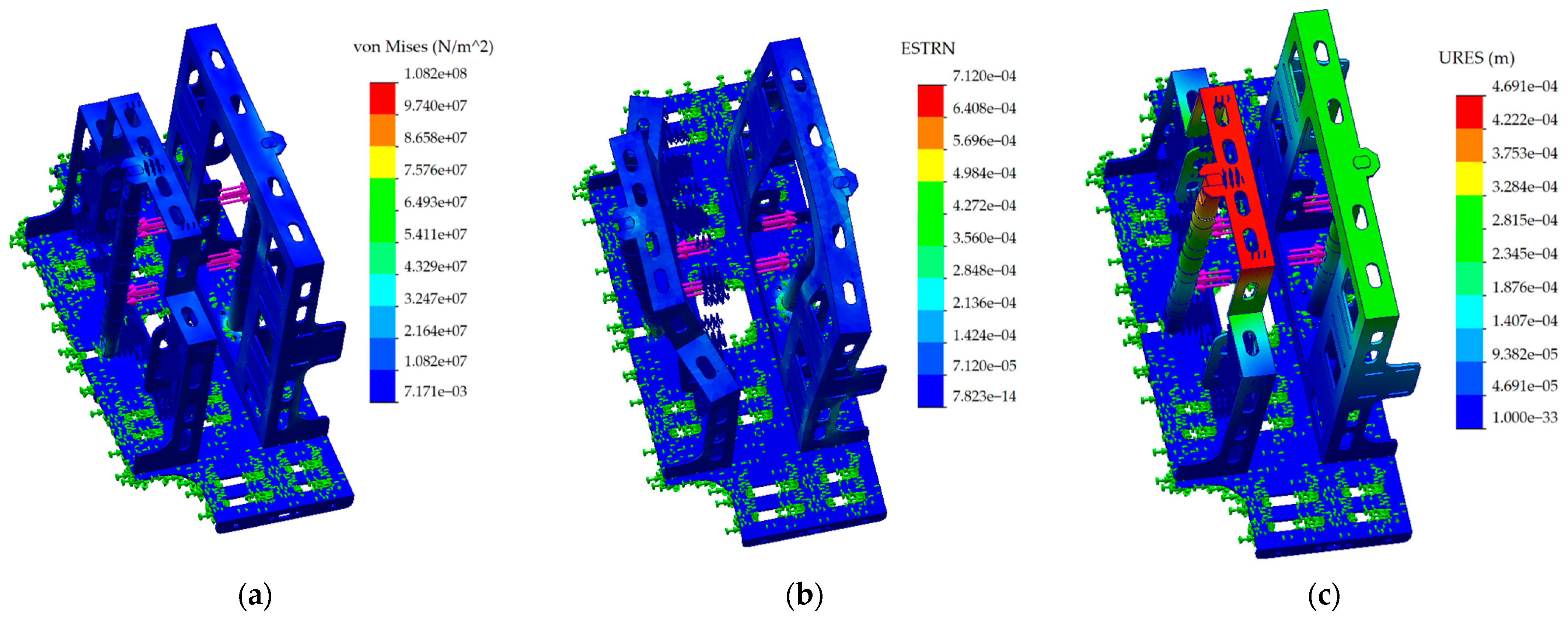
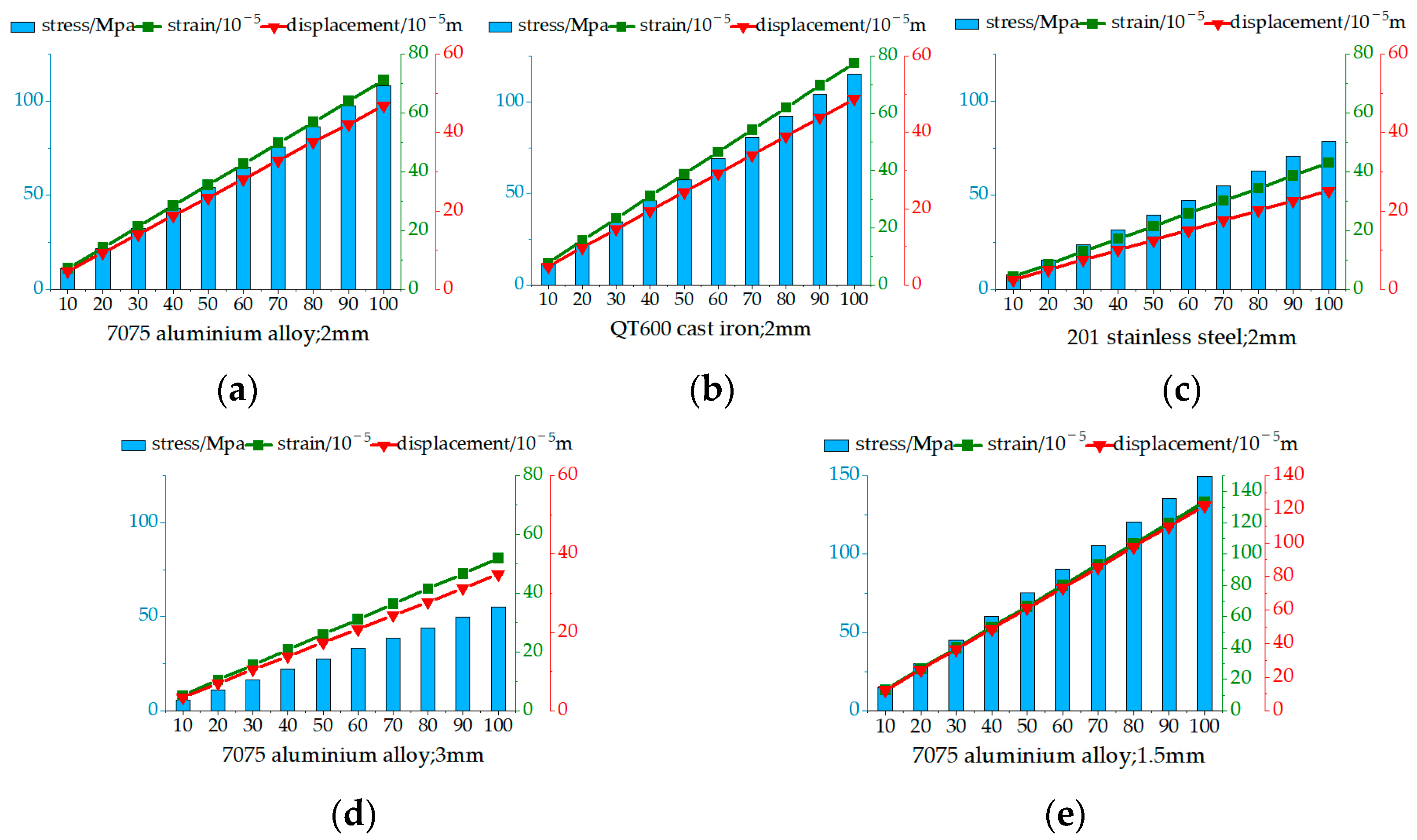
4. Optimization Design

Section 2.1 analyzed the issues present in the tunnel retro-reflective ring. This climbing robot’s ability to move stably on the tunnel retro-reflective ring depends on the strength and stiffness of the designed Π-shaped framework. Below, Solidworks Simulation 2022 is used to perform deformation simulation analysis on the Π-shaped bracket, to confirm the appropriate material and thickness.
Due to the structure being welded between the bottom plates, fixed constraints are set at the bottom. Compression spring constraints are applied at the ends of the shaft. Additionally, forces ranging from 0 N to 100 N, increasing in 10 N increments, are applied outward from the center of every wheel axle to simulate the increase in thickness of the clamped tunnel retro-reflective ring. The stress, strain, and displacement cloud map of 7075 aluminum alloy with a thickness of 2 mm is shown in Figure 12.
After confirming the shape of the main framework, the analysis of the main framework is as follows:
(1)
The influence of different materials on the deformation of the frame.
The thickness is uniformly set to 2 mm, and the materials selected are 201 stainless steel, QT600 cast iron, and 7075 aluminum alloy, with their respective parameters shown in Table 1.
Figure 13a–c depict the relationship between stress, strain, and displacement with increasing loads, after simulation analysis for each material. It can be observed that the deformation degree follows the order: 201 stainless steel < 7075 aluminum alloy < QT600 cast iron. Although 201 stainless steel exhibits the least deformation, its density is too high, leading to an increase in the overall weight of the robot. This necessitates greater pressure from the compression springs to ensure stability, and the increased weight also requires more energy, significantly reducing the robot’s operational duration. The density and degree of deformation of QT600 are relatively high. Therefore, considering both the density and deformation degree, 7075 aluminum alloy is chosen as the material for the Π-shaped bracket.
(2)
The influence of sheet thickness on the deformation of the frame.
The material is uniformly set to 7075 aluminum alloy, with thicknesses of 2 mm, 3 mm, and 1.5 mm considered. The simulation results are depicted in Figure 13a,d,e. As the thickness increases, the total deformation displacement of the frame continuously decreases. However, with increasing thickness, the mass inevitably increases as well. A thickness of 3 mm does indeed provide high stability, but the mass is too large, and deformation at 1.5 mm is too large, making it unsuitable for use. Within an acceptable range of deformation, a thickness of 2 mm is chosen for the main framework.
Ultimately, 7075 aluminum alloy with a thickness of 2 mm is selected as the material for the Π-shaped bracket. From Figure 13a, it can be observed that at 100 N, the maximum displacement is only 469 μm, with a mass of only 0.9 kg.

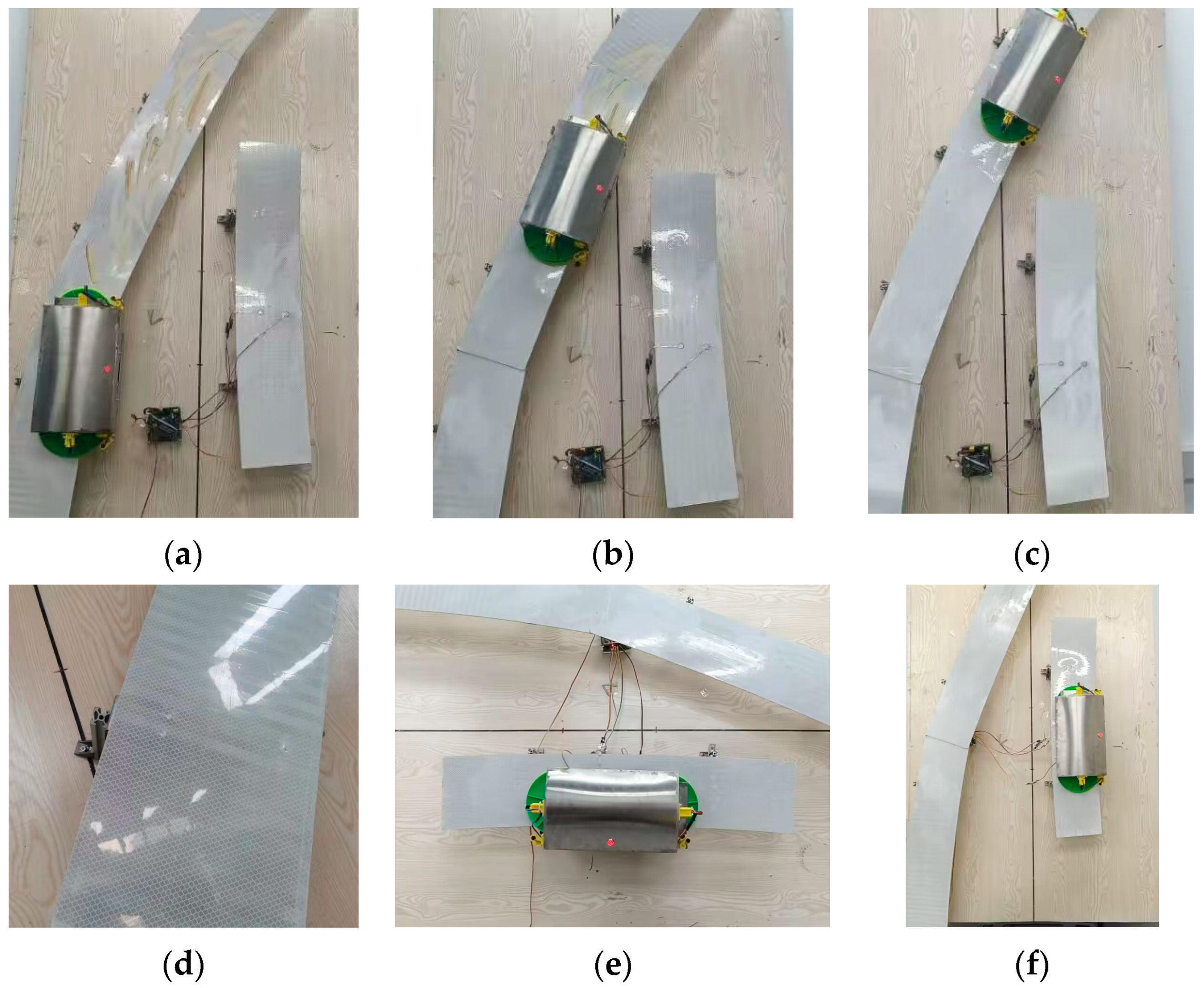
5. Experiments and Analysis

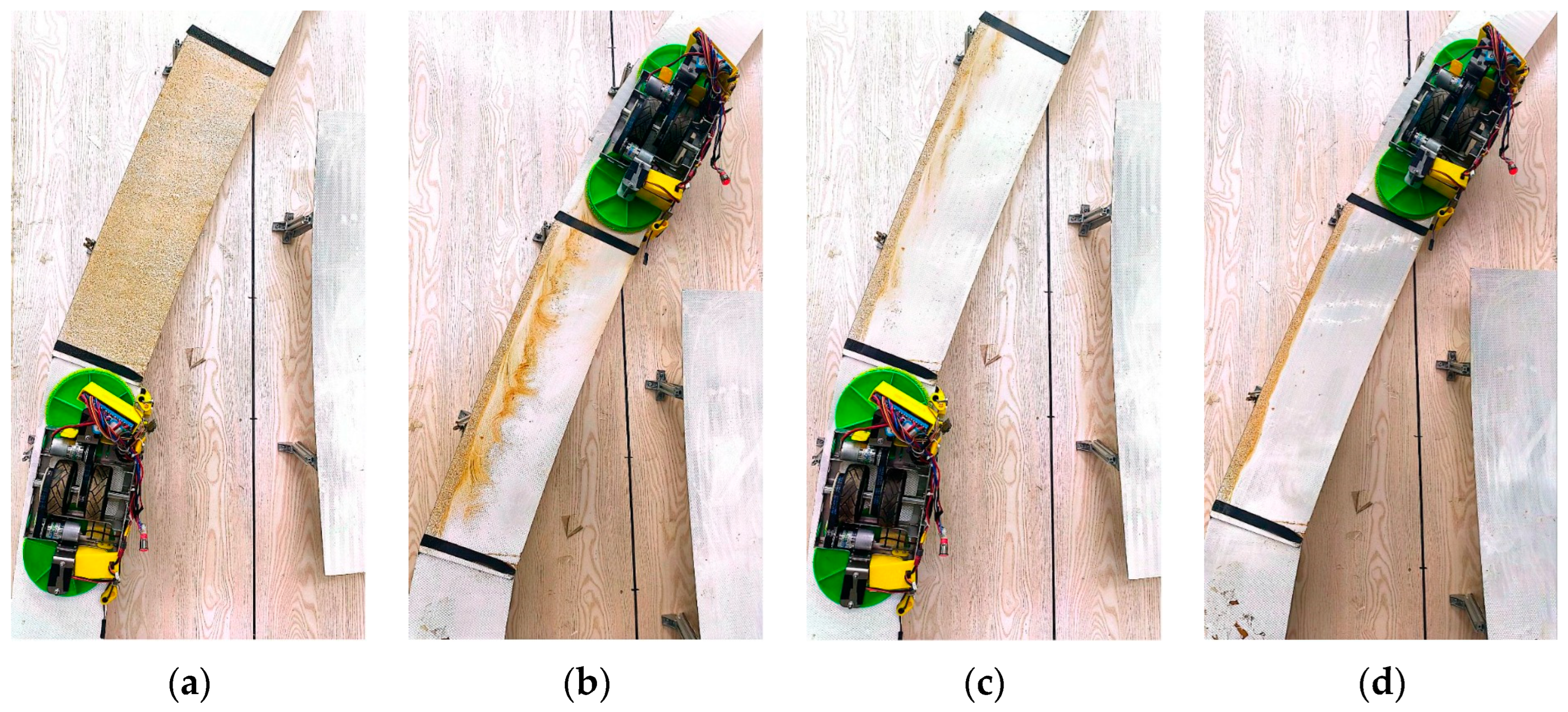
5.1. Analysis of Stable Climbing Experiments

Inside the laboratory, the real reflective panels purchased are assembled and fixed using the same method as inside the tunnel. They are secured with right-angled aluminum plates, to simulate the real installation environment of the retro-reflective ring inside the tunnel. The climbing performance is illustrated in Figure 14. Figure 14a–c illustrate the stable working state and cleaning effect of the climbing robot on the tunnel retro-reflective ring, while Figure 14d provides an enlarged view of the cleaning effect. Figure 14e,f depict the clamping effect of the climbing robot on horizontal and vertical retro-reflective rings, respectively.
During the climbing process, four sets of thin film pressure sensors are placed at the locations where the four sets of walking wheels pass, to test the pressure. These tests can be conducted on different thicknesses, with a 5 mm thickness used to simulate a stepped retro-reflective ring and a 6 mm thickness used to simulate the stacking of aluminum plates. The pressure of each walking wheel is tested multiple times and the average value is taken, with the results shown in Figure 15.
From Figure 15, on the 2.5 mm thick retro-reflective ring, the pressure borne by the two wheels on the working side is relatively small. The pressure exerted by Wheel 1 and Wheel 2 on the reflective plate is 27.96 N and 37.91 N, respectively. The pressure borne by the rear wheels is higher, with Wheel 3 and Wheel 4 exerting pressures of 44.75 N and 56.45 N on the reflective plate, respectively. The reason for this is analyzed in the static moment analysis above; the lack of complete symmetry causes a shift in the center of mass, resulting in higher pressure on one side.
However, the spring-loaded structure allows the robot to grip retro-reflective rings of different thicknesses, whether it is a stepped retro-reflective ring or an aluminum plate overlay. Additionally, it has a double-sided clamping mechanism that prevents tilting due to insufficient pressure and the cleaning device also provides auxiliary support to keep the robot stable.
Next, the parameters will be plugged into the calculation. The known parameters are m = 4.7 kg, assuming μ1 is 0.3, μ2 is 0.4, μf is 0.1, and g is 9.8 m/s2. Static analysis on a 2.5 mm reflective plate yields:
i = 1 4 F n i = 167.07   N > 2 · 4.7   kg · 9.8   m / s 2 0.3 + 0.4 = 131.6   N
The reduction ratio of the reducer is 1.6 and the rated torque with the motor is 2.4 N·m. The minimum required driving torque and the driving torque that four motors can bring is:
i = 1 4 T i > 0.047   m · 0.1 · 167.07   N + 4.7   kg · 9.8   m / s 2 = 2.95   N · m i = 1 4 T i = 4 · 1.6 · 2.4   N · m = 15.36   N · m i = 1 4 T i > i = 1 4 T i
Equations (10) and (11) indicate that the experimental test results meet the static and dynamic analysis results mentioned above, confirming that the sum of pressure and static friction is greater than gravity and that the selected motor model and reduction ratio provide sufficient driving torque. The results in Figure 14 also prove that it can grip, climb, and clean with stability.

5.2. Response Surface Methodology (RSM) Optimization Experiment

On the premise of the preliminary design of the robot and to ensure stability, the cleaning disc pressure, the walking wheel motor speed, and the cleaning disc motor speed are selected as experimental factors to analyze their effects on the cleaning performance. Firstly, single-factor experiments are conducted separately to explore the individual influences on the cleaning effect. Then, based on the principles of Box–Behnken [23] central composite design, with the number of cleaning times in a fixed area as the response variable, the optimization of cleaning is conducted through response surface analysis. The aim is to find the optimal combination of the three factors, to achieve the best cleaning performance.

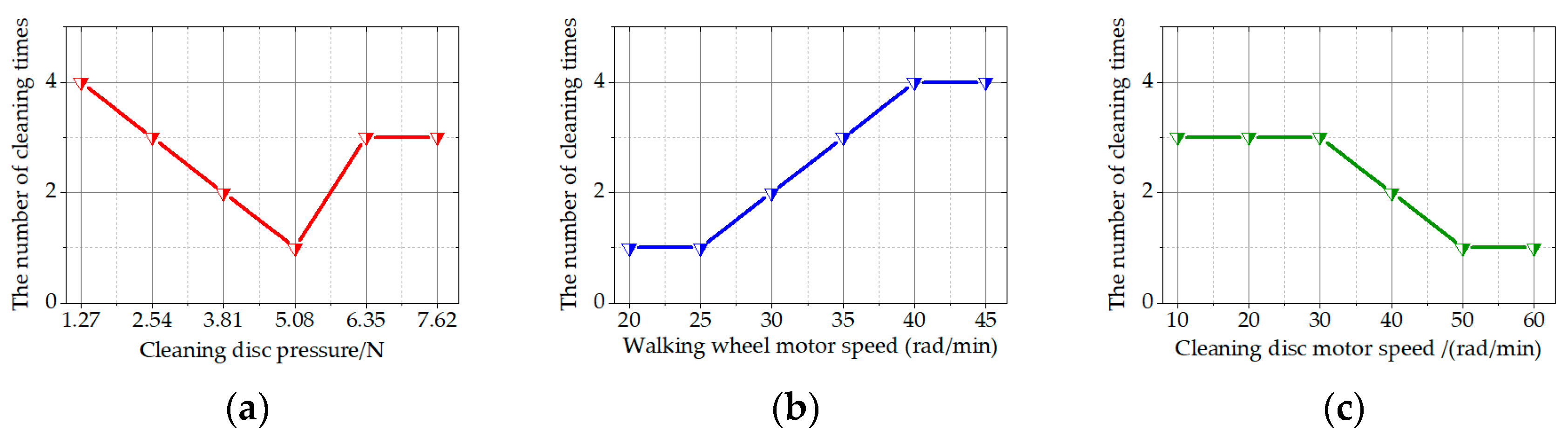
5.2.1. Single-Factor Test

Fixing the other two factors simultaneously, only one factor is altered at a time. Especially since the walking wheel speed affects the driving torque, the selected speed of the walking wheel must be within a range that ensures the robot’s stable driving capability. The experimental environment is created by using a roller brush covered with slightly wetted soil, to brush back and forth on the retro-reflective plate for a fixed number of times. Then, after waiting for it to air dry before experimenting, simulation of the actual situation of the tunnel retro-reflective ring, to the maximum extent possible, is performed. A section of the tunnel retro-reflective ring is selected as the testing area and the number of times the machine needs to clean this area is measured as the response. Figure 16 illustrates an example of cleaning three times. The results of the single-factor experiments are shown in Figure 17.
From Figure 17a, it can be observed that, with the walking wheel motor speed and the cleaning disc motor speed set at certain values, the number of cleanings initially decreases and then increases with increasing pressure. This indicates that when the pressure is too low, there is insufficient pressure between the cleaning disc and the retro-reflective ring, requiring multiple cleanings. On the other hand, when the pressure is too high, it may cause difficulty in the rotation of the cleaning disc and even damage the motor. Figure 17b reveals that a slower walking wheel motor speed results in better cleaning performance, without affecting climbing. However, excessively slow speed can prolong the working duration excessively, thereby affecting work efficiency. From Figure 17c, it is evident that a higher cleaning disc motor speed leads to better cleaning performance. Nevertheless, excessively high speeds can lead to increased energy consumption and thus may not be suitable for practical applications.
Moreover, both speed indicators show that once the speed rises or falls to a certain value, the number of cleaning times does not change significantly. This suggests that the optimal speed indicators are likely to occur at points where the slope of the curve changes.
Based on these factors, to achieve optimal cleaning performance with minimized cleaning times and energy consumption, while maintaining moderate machine speed, it is essential to identify the optimal combination of the three factors.

5.2.2. Response Surface Experimental Design

Based on the principle of Box–Behnken’s central composite experimental design and the above single-factor experimental results, the experimental factors for the three-factor, three-level orthogonal experiment are shown in Table 2 as follows:
The quadratic response surface regression analysis is performed on the experimental results using Design Expert 13 software, and the equation for the degree S is obtained as follows:
S = 1.2 + 0.875 A + 0.625 B 0.25 C   + 0.25 A C 0.25 B C   + 1.9 A 2 + 0.4 B 2 + 0.15 C 2
The experimental design and results are shown in Table 3:

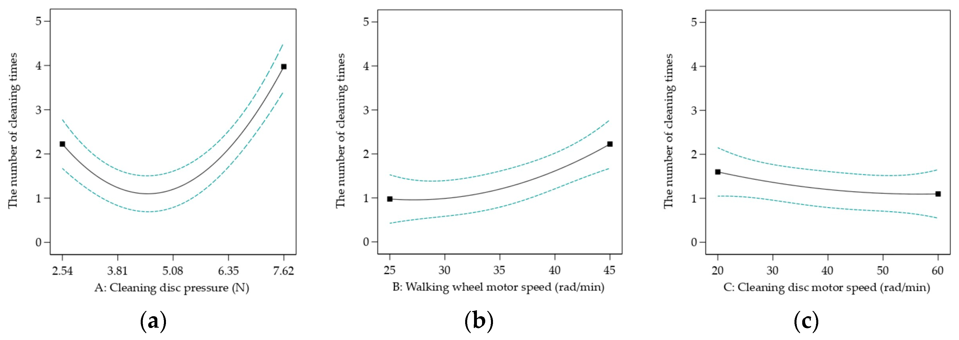
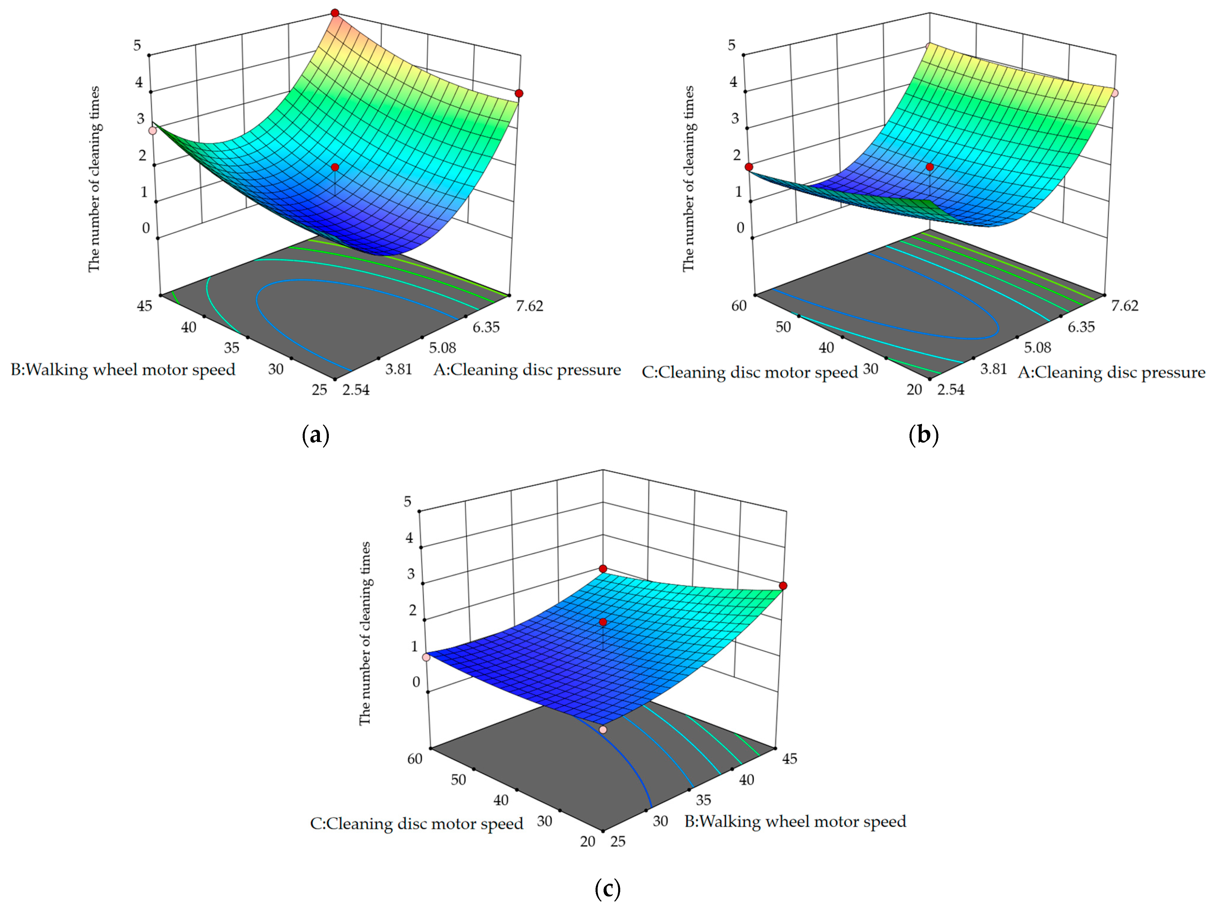
5.2.3. Response Surface Experimental Analysis

The regression equation analysis [24] results are shown in Table 4. It is evident that the model has a significant effect on the number of cleaning times S, while the mismatch term is extremely insignificant. The coefficient of determination R2 of the model is 0.9623, indicating that 96.23% of the change in S comes from the testing factor. The predicted R2 of 0.8117 is in reasonable agreement with the adjusted R2 of 0.9139; i.e., the difference is less than 0.2. The Adeq precision measurement signal-to-noise ratio is 13.0452, which is greater than 4, indicating that the model is good. Among them, A, B, and A2 are extremely significant, and the order of influence of the experimental factors is A > B > C.
Figure 18 shows the impact of a single factor on the number of cleanings, while Figure 19 shows the impact of a combination of two factors on the number of cleanings.
Specifically, as shown in Figure 18b,c and Figure 19c, the increase in the speed of the cleaning disc motor has a smaller impact than the decrease in the speed of the walking wheel motor.
Finally, through the analysis using Design Expert 13 software, the optimal cleaning conditions are found to be a cleaning disc pressure of 5.101 N, a walking wheel motor speed of 36.93 rad/min, and a cleaning disc motor speed of 38.252 rad/min. In fact, to ensure that the tunnel retro-reflective ring is not damaged, the cleaning disc should not apply too much pressure. Additionally, considering that each cleaning cycle should not be too long, the speed of the walking wheels should not be too slow. The overall energy loss of the machine should not be too substantial; therefore, the speed of the cleaning disc motor should not be excessively high. By optimizing these factors, the best combination will meet the above requirements. Finally, physical validation experiments are conducted based on the optimal combination, with most cleaning cycles being performed only once, achieving satisfactory results.

5.3. Discussion

Existing climbing robots are primarily designed to replace humans in completing tasks in complex environments [4,5,6]. They employ various climbing methods, such as magnetic adhesion [14,15], suction cups [11,12], adhesives [8], and so on. Previously, there has been no research on the application of climbing robots to tunnel retro-reflective rings. The main contribution of this paper is the proposal of a robot designed for climbing on tunnel retro-reflective rings, capable of overcoming challenging conditions such as stepped retro-reflective rings, stacked aluminum plates, and rivets. Additionally, using a response surface experiment, with three factors affecting the overall cleaning performance, the optimal parameter combination is found to achieve efficient cleaning of the tunnel retro-reflective rings. Furthermore, the robot is designed according to the most widely used size standards of retro-reflective panels inside Chinese tunnels, making it applicable for most tunnels.
However, the double-sided clamping and climbing method of this robot determines that it cannot climb arbitrarily, as with magnetic adhesion or suction cups. This robot is only suitable for clamping and climbing on thin and small surfaces, like tunnel retro-reflective rings, to accomplish cleaning tasks, indicating its incapability for cleaning other objects that require cleaning at heights. Moreover, it also fails to clean the blind spots of tunnel retro-reflective rings. These are the limitations of this robot, so the next step is to solve them.

6. Conclusions

This article proposes a climbing robot that can clean tunnel retro-reflective rings. Through the combination of mechanical and electronic systems, it can achieve automatic cleaning on tunnel retro-reflective rings, as well as manual remote controlled cleaning at designated points. It is especially capable of handling complex working conditions, such as stepped retro-reflective panels, aluminum plate overlays, and rivet protrusions.
Firstly, the mechanical structure, the hardware design, the microcontroller programming, and the principle of miniature photoelectric sensors are introduced, and its walking ability under different working conditions is analyzed. Then, the conditions that make the climbing robot stable are explored through static analysis, and the minimum driving torque is obtained through dynamic analysis. The stability of the robot is verified in the subsequent experimental section. After that, deformation simulation analysis is conducted on the Π-shaped main frame, using Solidworks Simulation 2022, to optimize the material and thickness of the frame. Finally, a mathematical regression model for cleaning disc pressure, walking wheel motor speed, and cleaning disc motor speed is established using response surface methodology. The optimal combination of the three factors is found. The cleaning disc pressure is 5.101 N, the walking wheel motor speed is 36.93 rad/min, and the cleaning disc motor speed is 38.252 rad/min, resulting in the best cleaning effect.
In the end, the robot can work stably on the retro-reflective rings of the tunnel and have good cleaning effects, without affecting the use of the tunnel.

Supplementary Materials

The following supporting information can be downloaded at https://www.mdpi.com/article/10.3390/act13060197/s1.

Author Contributions

Y.L. proposed the study. Y.L. and S.Y. designed the structure. S.Y. and R.C. performed and analyzed the simulations. Y.L. and S.Y. wrote the manuscript. Z.S. supervised and confirmed the research. All authors participated and contributed to the study. All authors have read and agreed to the published version of the manuscript.

Funding

This work was supported by the National Natural Science Foundation of China (No. 62177012) and the GUET Excellent Graduate Thesis Program (grant no. 19YJPYBS01).

Data Availability Statement

Data are contained within the article and Supplementary Materials.

Conflicts of Interest

The authors declare no conflicts of interest.

References

  1. Zhao, X.; Zhang, C.; Ju, Y.; Li, J.; Bian, Y.; Ma, J. Evaluation of tunnel retro-reflective arch in an extra-long tunnel based on the matter-element extension method. Accid. Anal. Prev. 2021, 150, 105913. [Google Scholar] [CrossRef] [PubMed]
  2. Deng, Z. A Tunnel Retro-Reflective Ring Cleaning Device. CN213086674U, 30 April 2021. [Google Scholar]
  3. Yang, Y.; Cao, J. A Highway Tunnel Retro-Reflective Ring Self-Cleaning Device and Its Cleaning Method. CN110882957B, 14 July 2023. [Google Scholar]
  4. Liu, J.H.; Padrigalan, K.E. The Kinematic Analysis of a Wind Turbine Climbing Robot Mechanism. Appl. Sci. 2022, 12, 1210. [Google Scholar] [CrossRef]
  5. Lu, X.; Zhao, S.; Liu, X.; Wang, Y. Design and analysis of a climbing robot for pylon maintenance. Ind. Rob. 2018, 45, 206–219. [Google Scholar] [CrossRef]
  6. Bogue, R. Climbing robots: Recent research and emerging applications. Ind. Rob. 2019, 46, 721–727. [Google Scholar] [CrossRef]
  7. Chu, B.; Jung, K.; Han, C.S.; Hong, D. A survey of climbing robots: Locomotion and adhesion. Int. J. Precis. Eng. Manuf. 2010, 11, 633–647. [Google Scholar] [CrossRef]
  8. Murphy, M.P.; Kute, C.; Mengüç, Y.; Sitti, M. Waalbot II: Adhesion recovery and improved performance of a climbing robot using fibrillar adhesives. Int. J. Robot. Res. 2011, 30, 118–133. [Google Scholar] [CrossRef]
  9. Schultz, J.T.; Beck, H.K.; Haagensen, T.; Proost, T.; Clemente, C.J. Using a biologically mimicking climbing robot to explore the performance landscape of climbing in lizards. Proc. R. Soc. B 2021, 288, 20202576. [Google Scholar] [CrossRef] [PubMed]
  10. Li, R.; Feng, S.; Yan, S.; Liu, X.; Yang, P.A.; Yang, X.; Shou, M.; Yu, Z. Wind Resistance Mechanism of an Anole Lizard-Inspired Climbing Robot. Sensors 2022, 22, 7826. [Google Scholar] [CrossRef]
  11. Zhu, H.; Guan, Y.; Wu, W.; Zhang, L.; Zhou, X.; Zhang, H. Autonomous pose detection and alignment of suction modules of a biped wall-climbing robot. IEEE/ASME Trans. Mechatron. 2014, 20, 653–662. [Google Scholar] [CrossRef]
  12. Guan, Y.; Zhu, H.; Wu, W.; Zhou, X.; Jiang, L.; Cai, C.; Zhang, L.; Zhang, H. A modular biped wall-climbing robot with high mobility and manipulating function. IEEE/ASME Trans. Mechatron. 2012, 18, 1787–1798. [Google Scholar] [CrossRef]
  13. Hu, Q.; Dong, E.; Sun, D. Soft modular climbing robots. IEEE Trans. Robot. 2022, 39, 399–416. [Google Scholar] [CrossRef]
  14. Enjikalayil Abdulkader, R.; Veerajagadheswar, P.; Htet Lin, N.; Kumaran, S.; Vishaal, S.R.; Mohan, R.E. Sparrow: A magnetic climbing robot for autonomous thickness measurement in ship hull maintenance. J. Mar. Sci. Eng. 2020, 8, 469. [Google Scholar] [CrossRef]
  15. Zhao, Z.; Tao, Y.; Wang, J.; Hu, J. The multi-objective optimization design for the magnetic adsorption unit of wall-climbing robot. J. Mech. Sci. Technol. 2022, 36, 305–316. [Google Scholar] [CrossRef]
  16. Spenko, M.J.; Haynes, G.C.; Saunders, J.A.; Cutkosky, M.R.; Rizzi, A.A.; Full, R.J.; Koditschek, D.E. Biologically inspired climbing with a hexapedal robot. J. Field Robot. 2008, 25, 223–242. [Google Scholar] [CrossRef]
  17. Liu, Y.; Sun, S.; Wu, X.; Mei, T. A wheeled wall-climbing robot with bio-inspired spine mechanisms. J. Bionic Eng. 2015, 12, 17–28. [Google Scholar] [CrossRef]
  18. Kim, H.; Kim, D.; Yang, H.; Lee, K.; Seo, K.; Chang, D.; Kim, J. Development of a wall-climbing robot using a tracked wheel mechanism. J. Mech. Sci. Technol. 2008, 22, 1490–1498. [Google Scholar] [CrossRef]
  19. Seo, K.; Cho, S.; Kim, T.; Kim, H.S.; Kim, J. Design and stability analysis of a novel wall-climbing robotic platform (ROPE RIDE). Mech. Mach. Theory 2013, 70, 189–208. [Google Scholar] [CrossRef]
  20. Zhu, Y.; Wang, Y.; Huang, Y. Failure analysis of a helical compression spring for a heavy vehicle’s suspension system. Case Stud. Eng. Fail. Anal. 2014, 2, 169–173. [Google Scholar] [CrossRef]
  21. Akinfiev, T.; Armada, M.; Prieto, M.; Uquillas, M. Concerning a Technique for Increasing Stability of Climbing Robots. J. Intell. Robot. Syst. 2000, 27, 195–209. [Google Scholar] [CrossRef]
  22. Zhang, X.; Wu, Y.; Liu, H.; Zhong, D. Design and Analysis of wheel-foot Magnetic Adsorption Barrier Climbing Robot. J. Mech. Eng. 2024, 60, 248–261. [Google Scholar]
  23. Wang, D.; Xu, S.; Li, Z.; Cao, W. Analysis of the influence of parameters of a spraying system designed for UAV application on the spraying quality based on Box–Behnken response surface method. Agriculture 2022, 12, 131. [Google Scholar] [CrossRef]
  24. Benyounis, K.Y.; Olabi, A.G.; Hashmi, M.S.J. Multi-response optimization of CO2 laser-welding process of austenitic stainless steel. Opt. Laser Technol. 2008, 40, 76–87. [Google Scholar] [CrossRef]
Figure 1. Physical prototype: 1—shell; 2—walking wheel; 3—cleaning device; 4—compression spring; 5—main framework; 6—tunnel retro-reflective ring; 7—miniature photoelectric sensor; 8—remote control.
Actuators 13 00197 g001
Figure 2. The internal situation of the retro-reflective ring in the tunnel. (a) Realistic installation effect of retro-reflective ring inside tunnels; (b) retro-reflective ring sample; (c) the distance between the wire duct and the retro-reflective ring; (d) installation status of the back of the retro-reflective ring.
Actuators 13 00197 g002
Figure 3. Machine model: 1—walking wheel; 2—cleaning device; 3—miniature photoelectric sensor; 4—encoder deceleration motor; 5—synchronous belt; 6—active spindle; 7—compression spring; 8—Π-shaped framework.
Actuators 13 00197 g003
Figure 4. Machine appearance.
Actuators 13 00197 g004
Figure 5. Cleaning institutions. (a) Clean model: 1—nut; 2—bolt; 3—compression spring; 4—support plate; 5—cleaning disc; 6—electrical machinery; 7—side panels of the main frame; 8—external extension plate; (b) Spring compression principle; (c) The relationship between spring elasticity and compression.
Actuators 13 00197 g005
Figure 6. Hardware circuit scheme.
Actuators 13 00197 g006
Figure 7. Principle of PID speed control.
Actuators 13 00197 g007
Figure 8. Principle of miniature photoelectric sensor.
Actuators 13 00197 g008
Figure 9. Static force situation. (a) The robot in a stationary clamping situation; (b) static force analysis; (c) distribution of identification numbers for the walking wheels: 1—the wheel closest to the tunnel inner wall on the working face; 2—the other wheel on the working face; 3—the wheel closest to the tunnel inner wall on the backside; 4—the other wheel on the backside.
Actuators 13 00197 g009
Figure 10. Static moment situation.
Actuators 13 00197 g010
Figure 11. Force situation of climbing robot movement. (a) The force situation of the two walking wheels on the working face, (b) the force situation of the two wheels on the back.
Actuators 13 00197 g011
Figure 12. Cloud map of three indicators. (a) Stress cloud map, (b) strain cloud map, (c) displacement cloud map.
Actuators 13 00197 g012
Figure 13. Changes in stress, strain, and displacement of different materials and thicknesses with loading load. (a) The relationship between stress, strain, and displacement of 2 mm 7075 aluminum alloy with increasing load; (b) the relationship between stress, strain, and displacement of 2 mm QT600 cast iron with increasing load; (c) the relationship between stress, strain, and displacement of 2 mm 201 stainless steel with increasing load; (d) the relationship between stress, strain, and displacement of 3 mm 7075 aluminum alloy with increasing load; (e) the relationship between stress, strain, and displacement of 1.5 mm 7075 aluminum alloy with increasing load.
Actuators 13 00197 g013
Figure 14. Climbing, cleaning, and hovering conditions. (a) Climbing starting position, (b) climbing the middle position, (c) climbing finishing position. (d) Effect after cleaning. (e) Verification of horizontal climbing stability, (f) verification of vertical climbing stability.
Actuators 13 00197 g014
Figure 15. The pressure distribution and sum of four wheels with different clamping thicknesses.
Actuators 13 00197 g015
Figure 16. Examples that require cleaning three times. (a) Cleaning starting point, (b) cleaning once, (c) cleaning twice, (d) cleaning three times.
Actuators 13 00197 g016
Figure 17. The results of the single-factor experiments. (a) Cleaning disc pressure single factor test, (b) walking wheel motor speed single factor test, (c) cleaning disc motor speed single factor test.
Actuators 13 00197 g017
Figure 18. Response curve. (a) S = f (A, 35, 40); (b) S = f (5.08, B, 40); (c) S = f (5.08, 35, C).
Actuators 13 00197 g018
Figure 19. Response surface. (a) S = f (A, B, 40); (b) S = f (A, 35, C); (c) S = f (5.08, B, C).
Actuators 13 00197 g019
Table 1. Material parameters.
201 Stainless SteelQT600 Cast Iron7075 Aluminum Alloy
Density7859 kg/m37200 kg/m32830 kg/m3
Elastic modulus2.07 × 1011 Pa6.62 × 1010 Pa7.20 × 1010 Pa
Table 2. Factors and factor levels of the experiment.
FactorsLevel
−101
Cleaning disc pressure (A/N)2.545.087.62
Walking wheel motor speed(B/(rad/min))253545
Cleaning disc motor speed(C/(rad/min))204060
Table 3. The experimental design and results.
NO.ABCS
15.0825601
25.0835401
35.0835401
42.5435203
55.0835402
67.6245405
75.0845602
85.0835401
92.5445403
107.6235204
115.0835401
125.0825201
137.6235604
147.6225404
152.5425402
165.0845203
172.5435602
Table 4. Regression equation analysis of variance.
Sum of
Squares
Freedom of DegreeMean
Square
F-Valuep-ValueSignificance
Model26.8392.9819.880.0003significant
A6.1316.1340.830.0004**
B3.1313.1320.830.0026**
C0.510.53.330.1106
AB3.55 × 10–1513.55 × 10–152.37 × 10–141
AC0.2510.251.670.2377
BC0.2510.251.670.2377
A215.2115.2101.33<0.0001**
B20.673710.67374.490.0718
C20.094710.09470.63160.4529
Residual1.0570.15
Lack of Fit0.2530.08330.41670.751not significant
Pure Error0.840.2
Cor Total27.8816
Notes: ** means the influence is highly significant, p < 0.01.
Disclaimer/Publisher’s Note: The statements, opinions and data contained in all publications are solely those of the individual author(s) and contributor(s) and not of MDPI and/or the editor(s). MDPI and/or the editor(s) disclaim responsibility for any injury to people or property resulting from any ideas, methods, instructions or products referred to in the content.

