Abstract
Singularities are configurations where the number of degrees of freedom of a robot changes instantaneously. In parallel manipulators, a singularity could reduce the mobility of the end-effector or produce uncontrolled motions of the mobile platform. Thus, a singularity is a critical problem for mechanical design and model-based control. This paper presents a general sensor-based method to identify singularities in the workspace of parallel manipulators with low computational cost. The proposed experimental method identifies a singularity by measuring sudden changes in the end-effector movements and huge increments in the forces applied by the actuators. This paper uses an inertial measurement unit and a 3D tracking system for measuring the end-effector movements, and current sensors for the forces exerted by the actuators. The proposed sensor-based identification of singularities is adjusted and implemented in three different robots to validate its effectiveness and feasibility for identifying singularities. The case studies are two prototypes for educational purposes—a five-bar mechanism and an L-CaPaMan parallel robot—and a four-degree-of-freedom robot for rehabilitation purposes. The tests showcase its potential as a practical solution for singularity identification in educational and industrial robots.
1. Introduction
In robotics, a singularity is a configuration where the number of degrees of freedom (DOF) of the robot changes instantaneously [1,2]. In serial manipulators, a singularity constrains the mobility of the end-effector in at least one direction and generally appears at the boundary of the workspace [3]. However, parallel manipulators, or Parallel Kinematic Mechanisms (PKMs), have various types of singularities due to their closed kinematic chain architecture [4,5,6].
Gosselin and Angeles [7] classified the singularities of PKMs into three types by analysing the input-output kinematic velocity relationship. Type I singularities are analogous to the singular configurations in serial manipulators, i.e., the PKMs lose at least one DOF of the end-effector or mobile platform. In Type II singularities, despite the actuator of the PKM being locked, the mobile platform gains at least one uncontrollable motion [1]. Type III singularities combine the two previous types simultaneously and only appear under certain geometrical parameters of the links [7,8]. The singularities of a PKM have been classified in different manners [9,10,11,12,13], always stressing the loss of mobility or uncontrolled movements in the end-effector.
The consequences of singularities pose significant challenges to PKM design and control. Type I singularities amplify the forces required by the actuators to move the mobile platform, increasing electric current demands [2]. Conversely, Type II singularities generate uncontrolled motion that risks the integrity of the user and the PKM itself [14,15], and they degrade the model-based control laws, resulting in infinite control actions [16,17].
In non-redundant PKMs, singularities are identified using graphical procedures, analytical methods, or a combination of both. Graphical methods are usually based on PKM geometry [18,19]. Analytical methods can use Jacobian matrices from the input-output kinematic velocity relationship [20,21,22], Screw theory [23,24,25], or motion/force transmissibility [26]. These theoretical methods primarily rely on precise kinematic modelling of the PKM under study with offline implementations because of their substantial mathematical calculations. In [27], experimental measurements of the position and orientation (pose) reached by the end-effector and the force applied by the actuators were used to improve singularity identification based on kinematic models. In real PKMs, the kinematic model-based singularity identification described above faces the following challenges:
- Real-time implementation in resource-limited control units is hindered by the substantial mathematical calculations required. Combining singularity identification with control laws, such as computed torque control [17] or model predictive control [28], requires considerable computational resources.
- Modelling complexity varies across mechanical architectures, complicating the establishment of a general approach applicable to different PKMs. A comprehensive examination of PKM modelling and its associated challenges is provided [29].
- Non-model effects, such as joint clearances, add complexity to determining the appropriate singularity proximity thresholds. Some approaches for measuring the closeness to a singularity are provided in [30,31].
In order to address the challenges faced by existing methods, this paper proposes a novel approach to identifying Type I and Type II singularities in non-redundant PKMs using only sensor measurements. The sensor-based singularity identification method is designed to detect unexpected movements of the end-effector and sharp oscillations in the forces applied by the actuators. By utilising inertial or vision sensors to measure the motion of the end-effector and current sensors to measure the actuator forces, the proposed method bypasses the need for accurate kinematic modelling. The avoidance of kinematic modelling allows for real-time implementation across resource-limited control units. The singularity identification threshold is set by the average pose error and actuator current during normal operations of the real PKM, making the proposed method robust to non-model effects. Thus, the proposed singularity identification provides high adaptability to different PKMs with low complexity in implementation. The effectiveness of this method is validated through experiments conducted on two educational PKMs and a PKM designed for knee rehabilitation.
The remainder of this manuscript is organised as follows. Section 2 presents the singularities in a PKM and the problems for users and robots. Section 3 describes the proposed sensor-based procedure for identifying Type I and Type II singularities. Section 4 uses the proposed sensor-based procedure to identify Type I singularities in a 3-DOF PKM known as L-CaPaMan. Section 5 describes the sensor-based identification of Type II singularities in a five-bar planar mechanism. In both cases, the motion of the end-effector is detected by an inertial measurement unit, and current sensors measure the force applied by the actuators. Section 6 describes the identification of Type II singularities using a 4-DOF PKM for knee rehabilitation as a case study. In this case, the motion of the end-effector is measured by a 3D tracking system. Finally, the main conclusions are presented in Section 7.
2. Singularities in Parallel Manipulators
A parallel robot, or Parallel Kinematic Mechanism (PKM), is a mechanism that controls the location and orientation of the end-effector or mobile platform using at least two open kinematics chains [1]. The position and orientation of the mobile platform, often referred to as the pose of the end-effector, are represented by a vector . The translational DOFs of the PKM are represented by , , and , and the rotational DOFs are represented by , , and . The pose is constrained by the kinematic arrangement of the open kinematic chains, which dictate the permissible motions of the mobile platform [2].
Each open kinematic chain, also known as a limb, consists of interconnected links joined by joints. The relative motion between the links within a limb is described using generalised coordinates, denoted as , which may represent translational or rotational motion at any given instance [2]. The pose is controlled by a subset of active or actuated joints .
The kinematic structure of a PKM typically includes key elements such as the mobile reference frame attached to the end-effector and the fixed reference frame affixed to the base or fixed platform. Figure 1 illustrates a schematic representation of a PKM, highlighting these main kinematic elements.
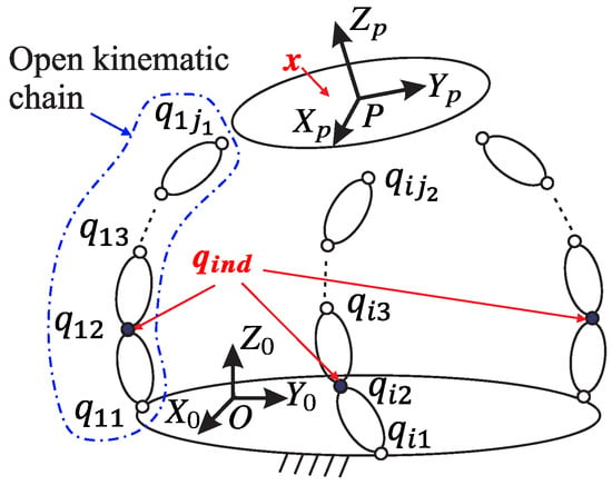
Figure 1.
A general scheme of a PKM and its main kinematic elements. The pose of the end-effector and the active joints are shown in red.
The inverse and forward kinematics problems of the PKM are defined by the input-output constraint equations
where and are vectors that represent the input and output variables of the PKM, respectively.
Taking the time derivatives of Equation (1), the relationship between the output and input velocities is
where stands for the velocities in the actuators, represents the velocities of the end-effector, and and represent the inverse and forward Jacobian matrices, respectively. For non-redundant PKMs, and are square matrices, with F as the DOFs of the mobile platform.
Based on the rank deficiency of the Jacobian matrices, Gosselin and Angeles [7] defined three types of singularities:
Type I: The matrix becomes rank-deficient, i.e., the determinant of the matrix is zero (). The mobile platform of the PKM loses mobility in at least one direction despite having a set of non-zero velocities in the actuators, . Figure 2a shows a five-bar planar mechanism, or 5R PKM (where R stands for revolute joint), in this singular configuration.
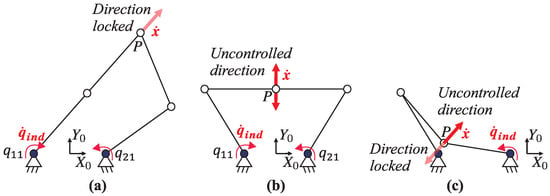
Figure 2.
Examples of singularities in a 5R PKM: (a) Type I; (b) Type II; (c) Type III in a 4R PKM.
Type II: Here, the Jacobian matrix becomes rank-deficient (). In this case, despite all actuators being locked (), the mobile platform of the PKM experiences at least one uncontrollable motion. Figure 2b depicts a Type II singularity configuration. Under this condition, if an external action is applied to the mobile platform, the PKM moves despite the actuators being locked.
Type III: Both and become rank-deficient simultaneously. This configuration occurs only for specific geometric parameters of the links. Figure 2c shows an example using a four-bar mechanism, or 4R PKM.
3. Sensor-Based Identification of Singularities
Type I and Type II singularities cause instantaneous changes in the end-effector motion [1,2]. Hence, a motion sensor can identify singularities by identifying disruptions in the end-effector motion. Such disruptions necessitate an increase in the force applied to the actuators. Since force correlates with the electric current consumed by the actuators, incorporating current sensors could measure this increment in force. Therefore, this work proposes an experimental identification of the singularities of a PKM based on sudden changes in the end-effector motion and the corresponding electric current consumed by the actuators.
Figure 3 shows a block diagram of the proposed sensor-based procedure. The procedure requires the reference pose of the mobile platform , the measured pose , and the current consumed by the actuators . Singularities are identified by calculating the pose error and the time derivative of the electric current consumption .
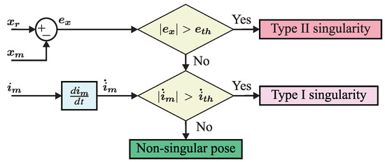
Figure 3.
Scheme of the proposed sensor-based procedure for identifying PKM singularities.
The closeness to a singularity is identified when exceeds the threshold of the permitted motion disturbance . If the end-effector exceeds the permitted motion disturbance , the PKM reaches a Type II singularity. This singularity is considered potentially dangerous because the end-effector presents uncontrolled motions. If is within the range of motion (), and increases suddenly over a certain limit, , it is a singularity Type I. This paper considers a Type I singularity non-dangerous because a PKM maintains its stiffness despite the reduction in the mobility of the end-effector. In contrast, Type II singularities are potentially dangerous because the end-effector becomes unstable, reducing its controllability.
The thresholds and are defined based on the operating specifications of the PKM. The threshold is defined as the average pose error admissible in the F DOFs for the fundamental movements of the PKM. In contrast, is defined as the instantaneous change in the average current consumed by the actuators during the fundamental movements of the PKM. Considering that the control unit is discrete, could be calculated for a constant sample time as
where is the sample time from the control unit.
The proposed identification method is based on the following assumptions:
- The working conditions of the PKM remain constant during its principal or fundamental movements. The fundamental movements represent the most commonly performed actions by the PKM within a given task. Variations in payload and wear and tear over the PKM’s lifetime are not taken into account.
- The sensor signals are assumed to be minimally affected by noise, either through hardware or software filtering mechanisms.
- The control unit works at a constant sample time.
The proposed procedure identifies singularities based solely on motion and electric current measurements. Therefore, this work introduces a rapid sensor-based method to identify singularities of PKMs, which is suitable for offline and online applications.
If the thresholds and are defined for the principal movements of the PKM, the proposed method provides robust detection of singularities that involve sudden movement changes or drastic current increments. Moreover, the proposed method can detect constraint singularities, which occur when the constraint wrenches from the limbs disappear, resulting in effects similar to Type II singularities [11].
The exclusive reliance on sensor measurements ensures that the proposed identification procedure is computationally efficient, rendering it suitable for control units with limited resources, such as robotics prototypes in engineering education. Moreover, by circumventing the need for kinematic models, the proposed method offers broad applicability, reducing the time investment required for implementation. In cases with enough computation resources, the proposed sensor-based identification procedure could be used for fast initial identification of singularities prior to verifying them using an analytical method.
The current research focuses on analysing the features of the proposed method under constant working conditions across different PKMs. The robustness of the proposed technique under varying working conditions, payload changes, and noise sensor signals is not analysed.
The following sections describe the setup and implementation of the proposed sensor-based identification of singularities in two PKMs developed for educational purposes and a prototype of a PKM for knee rehabilitation.
4. Case Study: L-CaPaMan
L-CaPaMan is a prototype of a PKM designed for earthquake simulation, featuring three DOFs [32]. This PKM operates by controlling translation along the axis and rotations and using three angular actuators, denoted as , , and , as illustrated in Figure 4a.
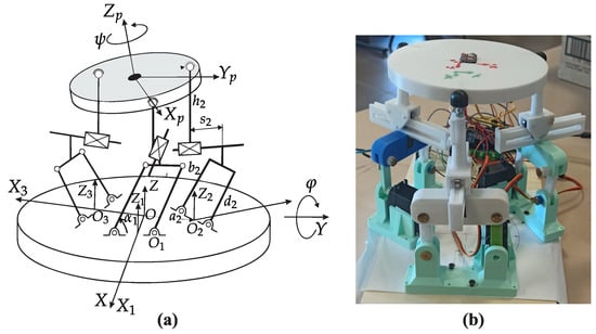
Figure 4.
L-CaPaMan PKM [32]: (a) kinematic design; (b) current prototype.
The positioning of the end-effector along and , along with the lengths of the three strokes , is intricately tied to the three DOFs , , and , rendering them passive variables. Geometric lengths represented by , , , and determine the specific connection points between the end-effector and the fixed platform. The coordinates frame stands for the local system at each limb .
For experimental validation, a cost-effective prototype of L-CaPaMan, featuring a 3D-printed structure [32], was employed, as depicted in Figure 4b. This figure illustrates the physical realisation of the prototype, providing insights into its practical implementation.
The proposed sensor-based identification shown in Figure 3 was applied to detect Type I singularities in the current L-CaPaMan prototype shown in Figure 4b. The sensor-based identification of singularities was carried out online using Matlab code during the execution of two singular trajectories, which are defined as follows:
- TM1: Crossing two Type I singularities in the middle of two desired configurations.
- TM2: Starting from a Type I singularity to reach a non-singular pose.
The reference trajectories (TM1 or TM2) are sent from Matlab R2023a code to the control unit of the L-CaPaMan PKM via serial communications at a baud rate of 115,200. The control unit is an Arduino Mega, manufactured in Italy by Arduino.cc, that modifies the pose of the end-effector using three servomotors in the PKM. All the measurements are sent from the Arduino Mega to Matlab for numerical identification of the singularities. Figure 5 shows a schematic diagram of the sensor-based identification of Type I singularities for the L-CaPaMan PKM, and Algorithm 1 details the code executed in Matlab.
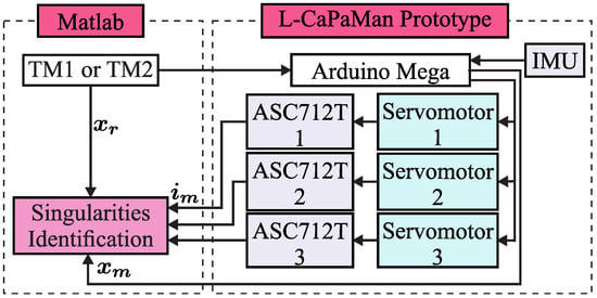
Figure 5.
Scheme for sensor-based identification of singularities in the L-CaPaMan PKM.
The current consumed by the servomotors is measured by three current sensors (ASC712T), which provide an analogue voltage proportional to the current at 120 kHz. These sensors have a range of ±5 A, an output sensitivity of 185 mV/A, and a supply voltage of 4.5 V to 5.5 V. The linear acceleration and the angular velocity of the mobile platform are measured by an inertial measurement unit (IMU) attached to point H. The IMU sensor is an MPU6050 powered at 5 V 800 Hz, with an acceleration range of ±2 g and a gyroscope range of ±125 degrees/s.
The fundamental motion for the L-CaPaMan PKM consists of sinusoidal translations in with simultaneous sinusoidal rotations in and . This fundamental motion is executed ten times in the L-CaPaMan PKM to set the thresholds and . The current prototype of the L-CaPaMan PKM has an average pose error of 2 degrees for and , and 3 mm along . The actuators require an average current of 150 mA, and the control unit runs at 50 Hz (20 ms). Thus, for the L-CaPaMan PKM, the parameters for identifying singularities are set as and A/s.
| Algorithm 1: Matlab pseudo-code for sensor-based identification of singularities in the L-CaPaMan PKM |
| Data: Reference Trajectories from TM1 or TM2 Result: Numerical Identification of Singularities initialise threshold and initialise serial communication with Arduino Mega i = 0 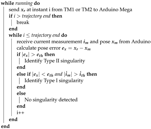 |
Results
The initial pose, expected singularity, and final pose of the L-CaPaMan PKM for testing trajectories TM1 and TM2 are listed in Table 1.

Table 1.
Data of the trajectories executed with L-CaPaMan.
Since TM1 mainly executes a vertical movement along , the motion error is shown only for this DOF. Figure 6a shows that the absolute position error in () remained under the corresponding threshold () for detecting Type I singularities during TM1. This means that the mobile platform experienced no sudden movement changes.
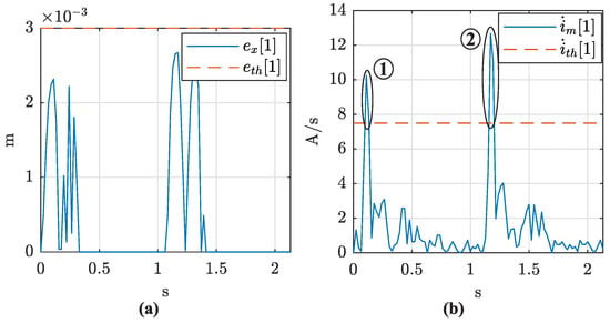
Figure 6.
Results of testing TM1 with the L-CaPaMan PKM: (a) absolute position error along ; (b) time derivative of the current consumed by actuator 1. The detected Type I singularities are enclosed in two black circles.
Although the mobile platform executed a controlled motion during TM1, the current consumed by the actuators presented two sudden changes. Figure 6b shows the rate of change of the current consumed by actuator 1. It verifies that detected the two peaks of the current corresponding to a Type I singularity. Figure 7 shows that the two peaks of the current detected by occurred when crossed zero.
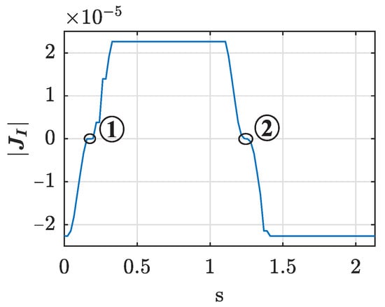
Figure 7.
Computed during TM1 with the L-CaPaMan PKM. The detected Type I singularities are enclosed in two black circles.
The testing of TM2 demonstrated a controlled motion () with a current peak at the beginning (). Figure 8 shows the absolute error in and the current consumed by actuator 1 during TM2. These results verify that the proposed experimental procedure is suitable for detecting Type I singularities.
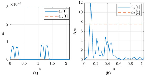
Figure 8.
Results of testing TM2 with the L-CaPaMan PKM: (a) absolute position error along ; (b) time derivative of the current consumed by actuator 1.
5. Case Study: Five-Bar Mechanism
The five-bar mechanism, also known as the 5R mechanism, is a planar PKM featuring two DOFs designed to position a point P within a defined plane . The name 5R originates from the five revolute joints denoted by the letter “R” that connect the links. Of these joints, two are actuated, typically connected to the fixed platform. The positions and of the point P are driven by two angular actuators represented by the generalised coordinates and (Figure 9a). The locations of the passive revolute joints, represented by and , are calculated based on the end-effector pose.
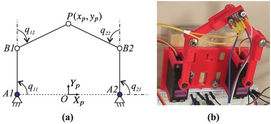
Figure 9.
5R mechanism: (a) kinematic design; (b) current prototype.
The kinematic analysis of the 5R mechanism requires defining a working mode. In this work, the 5R mechanism has a symmetrical architecture with the working mode . This working mode specifies that the actuator at corresponds to the negative solution for inverse kinematics, while the actuator at corresponds to the positive solution. For a detailed kinematic model of the 5R PKM, readers are referred to [33]. Figure 9b depicts the 5R PKM utilised in our research, developed specifically to demonstrate the impact of singularities in pick-and-place tasks to engineering students. Table 2 provides a list of the geometrical parameters for the current 5R PKM prototype.

Table 2.
Geometrical parameters for the 5R PKM prototype.
In this case, the experimental identification of singularities was carried out online in Matlab during the execution of two singular trajectories. Trajectory TM3 crosses a Type II singularity, and trajectory TM4 starts from a non-singular position and stops in a Type II singularity.
Analogous to Section 4, reference trajectories TM3 or TM4 are sent from Matlab code to the Arduino Mega for controlling the location of the 5R PKM via serial communications with a baud rate of 115,200. The linear acceleration and angular velocity of the B1P link are measured by an IMU MPU6050 in point P, and two ASC712T sensors measure the current consumed by the actuators. The ASC712T sensors provide a voltage proportional to the current at 120 kHz, with a range of ±5 A and a sensitivity at 185 mV/A. The MPU6050 measures linear acceleration at ±2 g and angular velocity at ±125 degrees/s with a frequency of 800 Hz.
A schematic diagram of the sensor-based identification of Type II singularities for the 5R PKM is shown in Figure 10, and its code executed in Matlab is depicted in Algorithm 2.
| Algorithm 2: MATLAB pseudo-code for sensor-based identification of singularities in the 5R PKM |
| Data: Reference Trajectories from TM3 or TM4 Result: Numerical Identification of Singularities initialise threshold and initialise serial communication with Arduino Mega i = 0 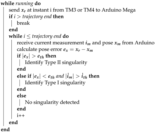 |
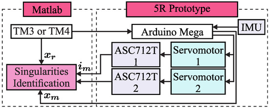
Figure 10.
Scheme for sensor-based identification of singularities in the 5R PKM prototype.
The 5R PKM under study develops a translation from to on the plane as its fundamental movement. After executing the fundamental movement ten times, the 5R PKM exhibits an average position error of 1.5 mm for and , and the actuators require an average current of 150 mA. Considering that the control unit runs at 20 ms, the parameters for identifying singularities are set as mm and A/s.
Results
The initial pose, expected singularity, and final pose for testing trajectories TM3 and TM4 are listed in Table 3.

Table 3.
Data of the trajectory executed with the 5R PKM prototype.
During the execution of TM3, the 5R mechanism lost control of the position of point P in the closeness to the expected Type II singularity. Figure 11a shows that the absolute position error for the vertical DOF () exceeded the corresponding threshold () starting from the time instant 2.4 s. This figure verifies that the PKM was unable to track the reference frame after 2.4 s, i.e., a Type II singularity occurred. During the execution of TM3, there were no sudden changes in the current consumed by the actuators. Figure 11b shows the absolute derivative of the current consumed by actuator 1 ().
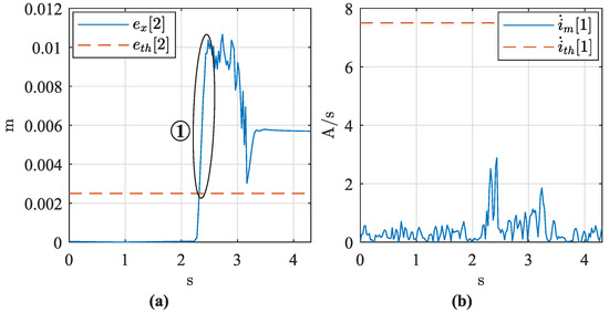
Figure 11.
Results of testing TM3 with 5R PKM: (a) absolute position error for ; (b) time derivative of consumed current by actuator 1. The detected Type II singularity is enclosed in a black circle.
According to Table 3, the Type II singularity was expected to appear at 2.8 s. However, the proposed sensor-based procedure identified the Type II singularity at 2.4 s. verified that the proposed sensor-based procedure anticipated the Type II singularity (see Figure 12). This is because non-modelled effects, such as clearances in joints, generate regions with singularities in actual PKMs [34].
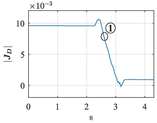
Figure 12.
Computed during TM3 with the 5R PKM. The detected Type II singularity is enclosed in a black circle.
The degeneracy of the end-effector motion with non-sudden changes in actuator currents was observed again towards the end of TM4 (Figure 13). Thus, the proposed procedure was able to identify Type II singularities in the 5R mechanism.
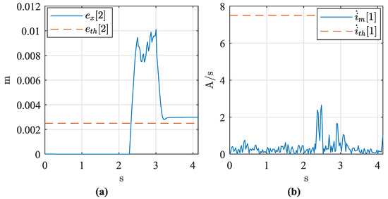
Figure 13.
Results of testing TM4 with the 5R PKM: (a) absolute position error for ; (b) time derivative of the current consumed by actuator 1.
6. Case Study: 4-DOF Parallel Manipulator
The 4-DOF parallel manipulator under analysis is a PKM built for knee rehabilitation and diagnosis purposes at Universitat Politècnica de València [35]. This PKM is named 3UPS+RPU due to the three external limbs having a UPS configuration and the central one having an RPU configuration. Figure 14 shows a kinematic representation of the 4-DOF PKM and its current prototype. The letters R, U, S, and P stand for revolute, universal, spherical, and prismatic joints, respectively, and “ ” identifies the actuated joint.
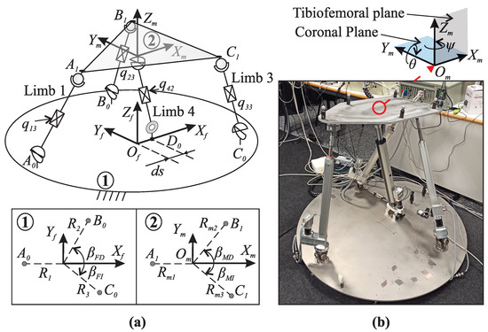
The four DOFs of the PKM consist of two translational movements (, ) in the tibiofemoral plane, along with rotations (, ) around the coronal and tibiofemoral planes, respectively [35]. These four DOFs are controlled by four linear actuators, denoted as , , and , as shown in Figure 14a.
The connections between the limbs and the fixed platform () are defined by geometrical variables such as , , , , , and . Conversely, the connections between the limbs and the mobile platform (, , , ) are determined by variables like , , , , and . These geometrical parameters are referenced to the fixed frame for the fixed platform and the moving frame for the mobile platform. Detailed geometrical parameters for the 3UPS+RPU PKM are provided in Table 4.

Table 4.
Geometrical parameters for the 3UPS+RPU PKM.
The experimental identification presented in Section 3 was applied to identify Type II singularities in the current 3UPS+RPU PKM prototype during the execution of two trajectories that crossed a Type II singularity, TM5 and TM6.
The sensor-based singularity identification method was developed on an industrial computer using ROS2, as reported in Figure 15. Reference trajectories TM5 or TM6 are sent to a PID controller that drives the four prismatic actuators of the PKM (, , , and ) using an ESCON 50/5 current amplifier powered at 24 V, manufactured in Sachseln, Switzerland by Maxon motor ag. The current amplifier provides a nominal power of 250 W and accurate feedback of the current consumed by the actuators using an analogue output channel with a 12-bit resolution at 53.6 kHz. The actual pose of the mobile platform of the 3UPS+RPU PKM is measured by a 3D tracking system (3DTS) manufactured by Optitrack, with an accuracy of 0.1 mm. The 3DTS system consists of 10 infrared Flex 13 cameras with a resolution of 1.3 Megapixels at 120 Hz.
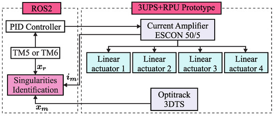
Figure 15.
Scheme for sensor-based identification of singularities in the 3UPS+RPU PKM.
The code implemented in ROS2 is depicted in Algorithm 3.
| Algorithm 3: ROS2 pseudo-code for sensor-based identification of singularities in the 3UPS+RPU PKM |
| Data: Reference Trajectories from TM5 or TM6 Result: Numerical Identification of Singularities initialise threshold and initialise communication with Optitrack 3DTS i = 0 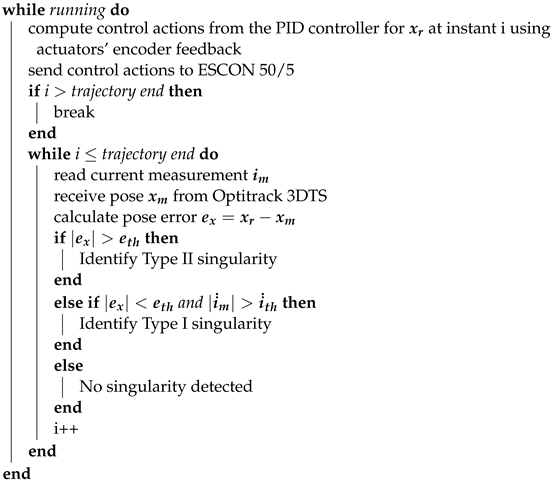 |
The 3UPS+RPU PKM performs three fundamental movements: (i) flexion of the hip, (ii) flexion-extension of the knee, and (iii) internal-external rotation of the knee [35]. After executing the fundamental movements ten times, the actual 3UPS+RPU PKM prototype exhibits an average position error of 9 mm for and , and 3 degrees for and , with an average of 5A for the current consumed by the actuators. Considering that the control unit runs at 10 ms, the parameters for the sensor-based identification procedure are set as and A/s.
Results
The initial pose, expected Type II singularity, and final pose of the 3UPS+RPU PKM for executing trajectories TM5 and TM6 are listed in Table 5.

Table 5.
Data of the trajectory executed with the 3UPS+RPU PKM prototype.
During the execution of TM5 and TM6, the 3UPS+RPU PKM lost control over the mobile platform in the closeness to the expected Type II singularities. Figure 16a shows that the PKM under study increased the error tracking on () at time instant 13.9. When the 3UPS+RPU PKM lost control over the end-effector, the current consumed by the actuators exhibited no sudden increments. Figure 16a shows the absolute derivative of the current consumed by actuator 1 () during the execution of TM5.
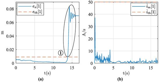
Figure 16.
Results of testing TM5 with the 3UPS+RPU PKM: (a) absolute position error for ; (b) time derivative of the current consumed by actuator 1. The detected Type II singularity is enclosed in a black circle.
Figure 17 shows that the instant of uncontrolled motion over the mobile platform appeared in the closeness to zero crossing of , i.e., a Type II singularity was detected.
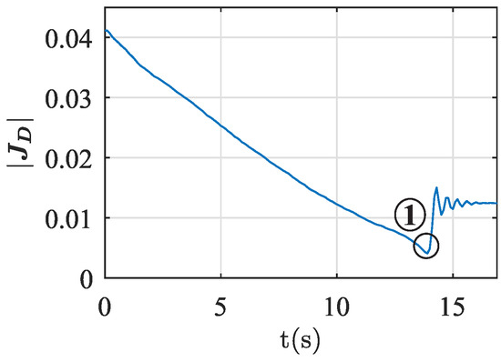
Figure 17.
Computed during TM5 with the 3UPS+RPU PKM. The detected Type II singularity is enclosed in a black circle.
In TM6, the Type II singularity was detected by an increment in the error tracking at time instant 13.0 s (Figure 18). Thus, the proposed sensor-based procedure demonstrated its capability to identify Type II singularities in spatial PKMs. In this work, the interaction between the 3UPS+RPU PKM and a human was avoided in order to reduce the external forces that could modify the expected singular configuration.
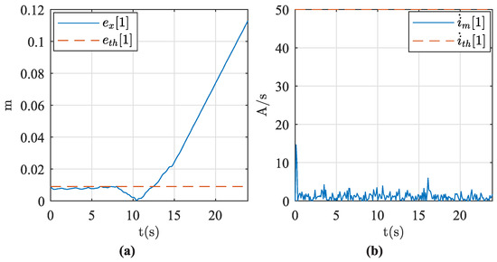
Figure 18.
Results of testing TM6 with the 3UPS+RPU PKM: (a) absolute position error for ; (b) time derivative of the current consumed by actuator 1.
7. Conclusions
The proposed sensor-based procedure has been successfully applied to identify Type I and II singularities in three non-redundant PKMs with different applications. The proposed sensor-based identification of singularities only requires measuring the actual position and orientation (pose) of the mobile platform and the current consumed by the actuators. In the closeness to a Type I singularity, the current consumed by the actuators increases suddenly with no changes in the pose tracking error. In contrast, a Type II singularity is identified by a sudden increment in the pose tracking error without abrupt changes in the electric current consumed by the actuators. The novel sensor-based identification of singularities could be extended to constraint singularities because the identification depends only on sensor measurements.
The sensor-based procedure for detecting singularities requires moderate time for adjustment. The sensor-based procedure is adjusted through the average pose tracking error and the average current consumed by the actuators during the fundamental movements of the PKM under study. Indirectly, the adjustment considers non-modelled effects, such as friction and clearances in joints, because all measurements are taken through experimentation on the actual PKM. Therefore, the proposed sensor-based procedure provides practical singularity identification for different PKMs.
The effectiveness of singularity identification depends on the accuracy of the sensor used to measure the motion of the end-effector and the current consumed by the actuators. An IMU requires numerical integration for measuring the pose of the end-effector. In contrast, a 3DTS directly measures the pose of the end-effector with high accuracy. Thus, a vision system is preferred over an IMU sensor for pose tracking.
The simplicity of the proposed sensor-based identification method of singularities reduces the computational cost. Thus, the proposed sensor-based singularity identification method is suitable for low-resource control units commonly used in educational robots and prototypes, especially in the first stage. Moreover, in industrial PKMs with high-performance control units, the proposed sensor-based procedure could be used for preliminary identification of singularities, which could then trigger an analytical method to verify the singularities. The use of the proposed singularity identification procedure for preliminary identification could allow the high-performance control units to focus on other tasks.
In future work, the authors will analyse the robustness of the proposed technique under varying working conditions, payload changes, and noise sensor signals. Potential solutions may involve refining the threshold definitions for detecting singularities, implementing advanced filtering techniques to mitigate noise effects, incorporating additional sensor data for improved reliability, and integrating artificial intelligence (AI) into the sensor-based singularity identification procedure. Moreover, the proposed sensor-based identification method will be leveraged to develop a singularity avoidance algorithm tailored for low-computation resource controllers, using the 5R and 3UPS+RPU PKMs as case studies. Additionally, the sensor-based identification method will be extended to detect constraint singularities in 3-DOF PKMs.
Author Contributions
Conceptualisation, M.C. and V.M.; methodology, V.M. and A.V.; software, A.V.; validation, V.M., M.C. and A.V.; formal analysis, J.L.P.; investigation, J.L.P.; resources, A.V.; data curation, J.L.P.; writing—original draft preparation, J.L.P.; writing—review and editing, J.L.P.; visualisation, J.L.P.; supervision, M.C.; project administration, V.M.; funding acquisition, V.M. and A.V. All authors have read and agreed to the published version of the manuscript.
Funding
This research was partially funded by Fondo Europeo de Desarrollo Regional (PID2021-125694OB-I00), cofounded by Erasmus+ project: Mechatronics for Improving and Standardizing Competences in Engineering (2022-1-ES01-KA220-HED-00089155).
Data Availability Statement
Data are contained within the article.
Conflicts of Interest
The authors declare no conflicts of interest.
Abbreviations
The following abbreviations are used in this manuscript:
| DOF | Degrees of freedom |
| PKM | Parallel Kinematic Mechanisms |
| ISA | Instantaneous Screw Axis |
| IMU | Inertial measurement unit |
References
- Briot, S.; Khalil, W. Dynamics of Parallel Robots—From Rigid Links to Flexible Elements, 1st ed.; Mechanisms and Machine Science; Springer: Cham, Switzerland, 2015; pp. 19–33. [Google Scholar] [CrossRef]
- Ceccarelli, M. Fundamentals of Mechanics of Robotic Manipulation; Springer: Cham, Switzerland, 2022; Volume 112, pp. 1–381. [Google Scholar] [CrossRef]
- Karger, A. Singularity Analysis of Serial Robot-Manipulators. J. Mech. Des. 1996, 118, 520–525. [Google Scholar] [CrossRef]
- Theingi; Chen, I.M.; Angeles, J.; Li, C. Management of parallel-manipulator singularities using joint-coupling. Adv. Robot. 2007, 21, 583–600. [Google Scholar] [CrossRef]
- Conconi, M.; Carricato, M. A New Assessment of Singularities of Parallel Kinematic Chains. IEEE Trans. Robot. 2009, 25, 757–770. [Google Scholar] [CrossRef]
- Di Gregorio, R. Instantaneous Kinematics and Singularity Analysis of Spatial Multi-DOF Mechanisms Based on the Locations of the Instantaneous Screw Axes. Mech. Mach. Theory 2024, 196, 105586. [Google Scholar] [CrossRef]
- Gosselin, C.; Angeles, J. Singularity analysis of closed-loop kinematic chains. IEEE Trans. Robot. Autom. 1990, 6, 281–290. [Google Scholar] [CrossRef]
- Taghirad, H.D. Parallel Robots, 1st ed.; CRC Press: Boca Raton, FL, USA, 2013. [Google Scholar] [CrossRef]
- Park, F.C.; Kim, J.W. Singularity Analysis of Closed Kinematic Chains. J. Mech. Des. 1999, 121, 32–38. [Google Scholar] [CrossRef]
- McAree, P.R.; Daniel, R.W. An Explanation of Never-Special Assembly Changing Motions for 3–3 Parallel Manipulators. Int. J. Robot. Res. 1999, 18, 556–574. [Google Scholar] [CrossRef]
- Zlatanov, D.; Bonev, I.; Gosselin, C. Constraint singularities of parallel mechanisms. In Proceedings of the 2002 IEEE International Conference on Robotics and Automation (Cat. No. 02CH37292), Washington, DC, USA, 11–15 May 2002; Volume 1, pp. 496–502. [Google Scholar] [CrossRef]
- Altuzarra, O.; Pinto, C.; Aviles, R.; Hernandez, A. A Practical Procedure to Analyze Singular Configurations in Closed Kinematic Chains. IEEE Trans. Robot. 2004, 20, 929–940. [Google Scholar] [CrossRef]
- Wu, C.; Liu, X.J.; Xie, F.; Wang, J. New measure for ’Closeness’ to singularities of parallel robots. In Proceedings of the 2011 IEEE International Conference on Robotics and Automation, Shanghai, China, 9–13 May 2011; pp. 5135–5140. [Google Scholar] [CrossRef]
- Voglewede, P.; Ebert-Uphoff, I. Measuring “closeness” to singularities for parallel manipulators. In Proceedings of the IEEE International Conference on Robotics and Automation, New Orleans, LA, USA, 26 April–1 May 2004; Proceedings, ICRA ’04. IEEE: Piscataway, NJ, USA, 2004; Volume 5, pp. 4539–4544. [Google Scholar] [CrossRef]
- Liang, D.; Mao, Y.; Song, Y.; Sun, T. Kinematics, dynamics and multi-objective optimization based on singularity-free task workspace for a novel SCARA parallel manipulator. J. Mech. Sci. Technol. 2024, 38, 423–438. [Google Scholar] [CrossRef]
- Choudhury, P.; Ghosal, A. Singularity and controllability analysis of parallel manipulators and closed-loop mechanisms. Mech. Mach. Theory 2000, 35, 1455–1479. [Google Scholar] [CrossRef]
- Six, D.; Briot, S.; Chriette, A.; Martinet, P. A controller for avoiding dynamic model degeneracy of parallel robots during type 2 singularity crossing. In New Trends in Mechanism and Machine Science; Springer: Cham, Switzerland, 2017; Volume 43, pp. 589–597. [Google Scholar] [CrossRef]
- Monsarrat, B.; Gosselin, C.M. Singularity Analysis of a Three-Leg Six-Degree-of-Freedom Parallel Platform Mechanism Based on Grassmann Line Geometry. Int. J. Robot. Res. 2001, 20, 312–328. [Google Scholar] [CrossRef]
- Merlet, J.P. Singular Configurations of Parallel Manipulators and Grassmann Geometry. Int. J. Robot. Res. 1989, 8, 45–56. [Google Scholar] [CrossRef]
- Corinaldi, D.; Callegari, M.; Angeles, J. Singularity-free path-planning of dexterous pointing tasks for a class of spherical parallel mechanisms. Mech. Mach. Theory 2018, 128, 47–57. [Google Scholar] [CrossRef]
- Pond, G.; Carretero, J.A. Formulating Jacobian matrices for the dexterity analysis of parallel manipulators. Mech. Mach. Theory 2006, 41, 1505–1519. [Google Scholar] [CrossRef]
- Merlet, J.P. Jacobian, Manipulability, Condition Number, and Accuracy of Parallel Robots. J. Mech. Des. 2006, 128, 199–206. [Google Scholar] [CrossRef]
- Joshi, S.A.; Tsai, L.W. Jacobian Analysis of Limited-DOF Parallel Manipulators. J. Mech. Des. 2002, 124, 254–258. [Google Scholar] [CrossRef]
- Ben-Horin, P.; Shoham, M. Singularity condition of six-degree-of-freedom three-legged parallel robots based on Grassmann–Cayley Algebra. IEEE Trans. Robot. 2006, 22, 577–590. [Google Scholar] [CrossRef]
- Slavutin, M.; Shai, O.; Sheffer, A.; Reich, Y. A novel criterion for singularity analysis of parallel mechanisms. Mech. Mach. Theory 2019, 137, 459–475. [Google Scholar] [CrossRef]
- Liu, X.J.; Wu, C.; Wang, J. A New Approach for Singularity Analysis and Closeness Measurement to Singularities of Parallel Manipulators. J. Mech. Robot. 2012, 4, 041001. [Google Scholar] [CrossRef]
- Hesselbach, J.; Maaß, J.; Bier, C. Singularity prediction for parallel robots for improvement of sensor-integrated assembly. CIRP Ann. Manuf. Technol. 2005, 54, 349–352. [Google Scholar] [CrossRef]
- Wang, Y.; Liu, Y.; Leibold, M.; Buss, M.; Lee, J. Hierarchical Incremental MPC for Redundant Robots: A Robust and Singularity-Free Approach. IEEE Trans. Robot. 2024, 40, 2128–2148. [Google Scholar] [CrossRef]
- Russo, M.; Zhang, D.; Liu, X.J.; Xie, Z. A review of parallel kinematic machine tools: Design, modeling, and applications. Int. J. Mach. Tools Manuf. 2024, 196, 104118. [Google Scholar] [CrossRef]
- Hubert, J.; Merlet, J.P. Static of Parallel Manipulators and Closeness to Singularity. J. Mech. Robot. 2009, 1, 011011. [Google Scholar] [CrossRef]
- Kapilavai, A.; Nawratil, G. Singularity distance computations for 3-RPR manipulators using extrinsic metrics. Mech. Mach. Theory 2024, 195, 105595. [Google Scholar] [CrossRef]
- Titov, A.; Russo, M.; Ceccarelli, M. Design and Performance of L-CaPaMan2. Appl. Sci. 2022, 12, 1380. [Google Scholar] [CrossRef]
- Liu, X.J.; Wang, J.; Pritschow, G. Kinematics, singularity and workspace of planar 5R symmetrical parallel mechanisms. Mech. Mach. Theory 2006, 41, 145–169. [Google Scholar] [CrossRef]
- Dai, Y.; Fu, Y.; Li, B.; Wang, X.; Yu, T.; Wang, W. Clearance effected accuracy and error sensitivity analysis: A new nonlinear equivalent method for spatial parallel robot. J. Mech. Sci. Technol. 2017, 31, 5493–5504. [Google Scholar] [CrossRef]
- Vallés, M.; Araujo-Gómez, P.; Mata, V.; Valera, A.; Díaz-Rodríguez, M.; Page, Á.; Farhat, N.M. Mechatronic design, experimental setup, and control architecture design of a novel 4 DoF parallel manipulator. Mech. Based Des. Struct. Mach. 2018, 46, 425–439. [Google Scholar] [CrossRef]
Disclaimer/Publisher’s Note: The statements, opinions and data contained in all publications are solely those of the individual author(s) and contributor(s) and not of MDPI and/or the editor(s). MDPI and/or the editor(s) disclaim responsibility for any injury to people or property resulting from any ideas, methods, instructions or products referred to in the content. |
© 2024 by the authors. Licensee MDPI, Basel, Switzerland. This article is an open access article distributed under the terms and conditions of the Creative Commons Attribution (CC BY) license (https://creativecommons.org/licenses/by/4.0/).