Article

A Framework for IBVS Using Virtual Work

1
School of Automation Science and Engineering, South China University of Technology, Guangzhou 510641, China
2
The Key Laboratory of Autonomous Systems and Networked Control, Ministry of Education, Guangzhou 510640, China
3
Unmanned Aerial Vehicle Systems Engineering Technology Research Center of Guangdong, South China University of Technology, Guangzhou 510641, China
4
School of Department of Electronic and Information Engineering, Shantou University, Shantou 515063, China
5
School of Automation, Jiangsu University of Science and Technology, Zhenjiang 212100, China
*
Author to whom correspondence should be addressed.
Actuators 2024, 13(5), 181; https://doi.org/10.3390/act13050181
Submission received: 26 March 2024 / Revised: 24 April 2024 / Accepted: 6 May 2024 / Published: 10 May 2024

Abstract

:
The visual servoing of manipulators is challenged by two main problems: the singularity of the inverse Jacobian and the physical constraints of a manipulator. In order to overcome the singularity issue, this paper presents a novel approach for image-based visual servoing (IBVS), which converts the propagation of errors in the image plane into the conduction of virtual forces using the principle of virtual work. This approach eliminates the need for Jacobian inversion computations and prevents matrix inversion singularity. To tackle physical constraints, reverse thinking is adopted to derive the function of the upper and lower bounds of the joint velocity on the joint angle. This enables the proposed method to configure the physical constraints of the robot in a more intuitive manner. To validate the effectiveness of the proposed method, an eye-in-hand system based on UR5 in VREP, as well as a physical robot, were established.

1. Introduction

Visual servoing is a crucial technology in intelligent robot systems, as it greatly enhances the ability of robots to perceive the environment. Various applications of visual servoing have been developed, including visual-based formation control [1,2], visual grasping [3,4], object tracking [5], and human–robot collaboration [6]. Visual servoing employs image features extracted from visual sensors, such as RGB cameras, as feedback for the controller. This approach makes the controller more flexible, reliable, and efficient when dealing with complex scenes.
Scientists have performed a great deal of work in visual servoing. These works are generally thought to fall into three categories. The first kind of visual servoing is called image-based visual servoing (IBVS) [7,8] and only uses the pixel coordinates of feature points as feedback. IBVS is insensitive to calibration errors. The second kind of visual servoing is called position-based visual servoing (PBVS) [9,10] and uses the 3D positions of the corresponding feature points as feedback for the controller. The 3D positions can be obtained through an RGB-D camera (RealSense) or a stereo camera (ZED). This means that PBVS needs the camera model to be accurate. The last kind of visual servoing is called hybrid visual servoing (HVS) [11,12], which combines 2D and 3D servoing techniques. HVS aims to improve precision and robustness in robotic tasks by integrating the advantages of different dimensional visual information. Compared to other servoing techniques, IBVS shows better movement in the image plane; however, it is not optimal for 3D motion because of the lack of 3D information. By contrast, PBVS has enhanced access to the movement path of the 3D space but cannot access the optimal route in the image plane. The hybrid method merges the information of the pixel plane and the 3D space. Both camera calibration and hand-eye calibration are indispensable in attaining highly accurate parameters, and these parameters are easily changed through the aging of the equipment or a change in the relative displacement between the camera and the manipulator. Therefore, research has focused on IBVS.
Researchers have extensively studied IBVS and made notable contributions. IBVS has been applied to robot development [1,2] and a quadcopter that mimics bird predation [4]. Keshmiri et al. [13] transformed pixel error propagation into the expected acceleration of the camera and used the computed torque method (CTM) to obtain the joint angular acceleration. Some researchers have used light field cameras for feature extraction [14], while others have usedutilized image feature extraction methods such as Bézier curves [15]. Incremental control laws have been used to avoid the multiple solutions yielded by some algorithms in inverse kinematics [16]. In addition to the common serial manipulators, there have been algorithmic studies conducted on parallel manipulator IBVS [17].
However, one common challenge faced by these algorithms is computing the inverse Jacobian matrix. For kinematic control near singularity, the joint movements of the manipulator may no longer satisfy the end-effector motion requirements, resulting in increases in joint movement velocity and acceleration. This can lead to significant force and torque demands, potentially causing the manipulator to be overloaded or generate abnormal accelerations, increasing energy consumption and mechanical component wear.
To solve this problem, Wang et al. [18] designed a virtual-goal-guided RRT algorithm for trajectory planning to fit the field of view and other physical constraints. Kazemi et al. [19] built a cyber–physical system that alternates between exploring the state space of the camera and the configuration space of the robot to obtain feasible camera/robot paths, thereby obtaining feasible feature trajectories in the image space. The main idea of these method is to plan a trajectory that is in compliance with constraints and avoids the singularities of the manipulator [20]. These methods attempt to avoid singular points, but they do not actually solve the problem of abnormal motion near the singular points.
In recent years, visual servoing methods based on the optimization algorithm have been developed for a redundant manipulator. These methods consider the visual servoing as a linear parameter-varying (LPV) model. A convex objective function of joint velocity has been built, and several constraints have been applied to the optimization algorithm. These constraints involve the angle, velocity, and acceleration of a joint, as well as the mapping between the error derivative and angular velocity. The servo task is then transformed into a quadratic programming (QP) problem. Afterward, a neural network is used to solve this QP problem. Hajiloo et al. [21] designed a robust model of a predictive controller to avoid the inverse of the Jacobian matrix. Jin et al. [22] built a dynamic recurrent neural network for redundant robots. Zhang et al. [23] changed the network mentioned in [22] and created a single-layer neural network for image-based visual servoing. Although these optimization algorithms merge the limitation of joint velocity and angle into one constraint, they approximate the curve portion of the merged constraint function using a line [24], which substantially wastes the feasible region and is not very intuitive.
Even though the above-mentioned controllers avoid the inverse of the Jacobian matrix, the optimization-based derivation process is complex, and once derived, the format is fixed. Inspired by the principle of virtual work, this article proposes a new visual servoing framework that converts errors into virtual forces using an impedance model and drives joint displacement using an admittance model through backward force propagation. This framework also avoids calculating the Jacobian matrix inversion and can design different impedance/admittance controllers based on different environments, involving support for linear and nonlinear functions.
The main contributions of this paper can be summarized by the following three aspects:
  • This study transforms the propagation of errors into the transmission of virtual forces and provides an intuitive understanding at the physical level. This transformation eliminates the inverse of the Jacobian matrix, thus avoiding the risks caused by the abnormal movements of certain joints near the singularities of a manipulator.
  • This article provides a function that expresses the limits of the joint angular velocity as a function of the angle. It integrates angle constraints, angular velocity constraints, and angular acceleration constraints. These limits can be obtained by directly setting the maximum and minimum values for the angle, angular velocity, and angular acceleration, without the need to calculate additional parameters.
  • This article demonstrates the design process of a controller, and its effectiveness was validated through simulation experiments and physical experiments.
The rest of this paper is structured as follows. Section 2 provides an overview of the model of the eye-in-hand system and presents fundamental definitions. In Section 3, the proposed image-based visual servoing framework is described in detail, along with a design example based on this framework. In Section 4, the experiments conducted using both the VREP simulation platform and real robots are discussed, and the results are analyzed. The main findings of this study are then summarized, and prospects for future research are discussed in Section 5.

2. System Modeling

In this section, the construction processes of both the camera and robot models are described in detail.

2.1. UR5 Robot Model

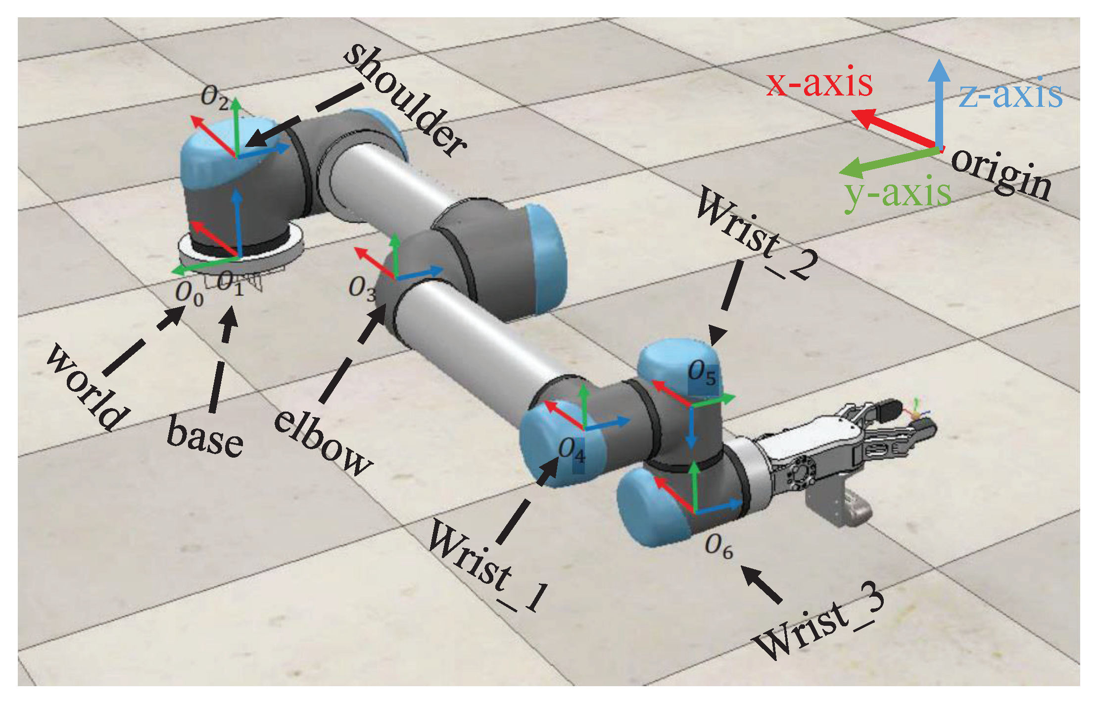
According to the D-H modeling [25], the coordinate definitions for each joint of the robot are shown in Figure 1.
Here, O 0 represents the world coordinate system, and O 1 through O 6 are the origin of the D-H coordinate system definitions for the first six joints. O 1 is overlapped with O 0 . In the process of defining the D-H coordinate system, first, the positive direction of the z-axis is directed along the axis of rotation toward the next joint. If the previous and current joints are parallel, the z-axis direction will be consistent with the previous one. Then, the x-axis, which should be perpendicular to and intersect with the z-axis of the previous coordinate system, is chosen. Next, the origin of the coordinate system is selected. If z i and z i 1 are not coplanar, the origin can be uniquely determined. When z i and z i 1 are coplanar, the origin can be determined by letting x i pass through O i 1 . Finally, the right-hand rule is used to determine the y-axis to complete the definition of the coordinate system.
Let v r R 6 be a column vector representing the motion of the end-effector defined in the base coordinate system. The upper three dimensions denote translation along the x-axis, y-axis, and z-axis, while the lower three dimensions represent rotation around the x-axis, y-axis, and z-axis. Subsequently, the pose of the end-effector and the Jacobian matrix between the end-effector motion v r and the joint velocity q ˙ can be obtained.
v r = J r q ˙
The Jacobian matrix J r is a 6 × N matrix, where N represents the degrees of freedom of the robot.

2.2. Camera Pin-Hole Model

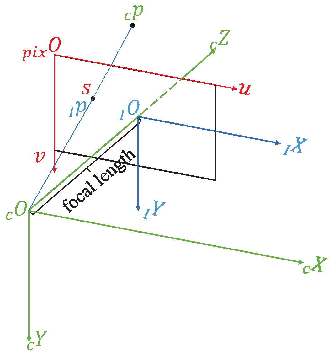
The key step in modeling the camera as a pin-hole model is to define three coordinate systems: the camera coordinate system, the image coordinate system, and the pixel coordinate system. In this paper, these coordinate systems are defined as illustrated in Figure 2.
  c O c X c Y c Z defines the camera coordinate system;   I O I X I Y defines the image coordinate system; and   p i x O u v represents the pixel coordinate system. Let   c p = [ X , Y , Z ] T ,   I p = [ x , y ] T , and s = [ u , v ] T denote the coordinates of a point described in the coordinate system of the camera, image, and pixel, respectively. The following relations can be obtained:
u v 1 = 1 Z f a x 0 u 0 0 f a y v 0 0 0 1 X Y Z
where f is the focal length of the camera, u 0 and v 0 are the center coordinates of the picture in the pixel frame, and a x and a y are factors that describe the pixel density.
Let v c and ω c denote the translation and rotation motion, respectively, along the x-axis, y-axis, and z-axis in the camera coordinate system. Therefore, there exists the following relationship between a static point   c p and the motion of the camera:
  c p ˙ = v c ω c ×   c p
In deriving Equation (2) and combining it with Equation (3), an image Jacobian is derived as Equation (4):
s ˙ = J img V c
where
J img = a x 0 0 a y · f Z 0 x Z x y f f 2 + x 2 f y 0 f Z y Z f 2 + y 2 f x y f x
is the image Jacobian, and v c R 6 is a six-dimensional column vector representing the motion of the camera in the camera coordinate system. The first three dimensions are linear velocity v c , and the last three dimensions are angular velocity ω c .

2.3. Eye-in-Hand System Model and Kinematics

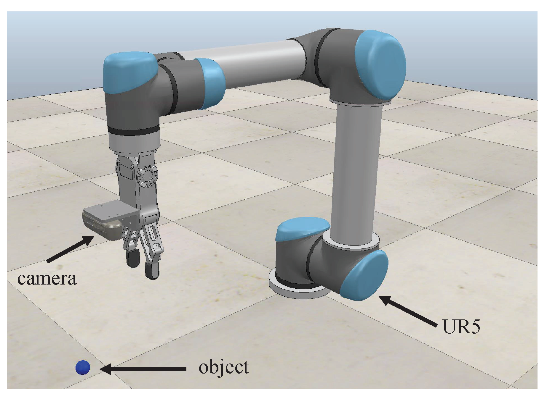
An eye-in-hand structure is illustrated in Figure 3.
As mentioned earlier, v r is defined in the robot’s base coordinate system, while v c is defined in the camera coordinate system. This study used the camera’s pose as the pose of the end-effector of the manipulator. According to the symbol definitions commonly used in [26] for rigid body motion, let   c R 0 represent the rotation matrix from the camera coordinate system to the base coordinate system. Consequently, the following relationship can be established:
v c = Γ v r ,
where
Γ =   c R 0 0 0   c R 0 .
Therefore, in combining the equations (Equations (1), (4), and (5)), the new Jacobian matrix relating the change in pixel position s ˙ to the joint motion q ˙ can be obtained:
s ˙ = J img Γ J r q ˙ .

3. Proposed Method

3.1. Proposed Framework

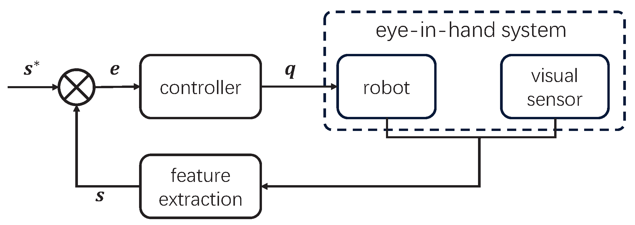
The general framework of an IBVS controller is shown in Figure 4. Here, s * represents the desired pixel position of a feature point in the image plane, while s represents the actual pixel position. The difference between the two is the pixel error. The visual servoing controller calculates the control outputs based on this error to control the motion of the manipulator. Additionally, in the hand-eye system, a camera captures images and updates the actual pixel position s of the feature points through image processing, providing feedback information to the visual servoing controller.
The error in the pixel coordinate system is defined as e = s * s , and then an impedance controller is employed to convert the error into a virtual elastic force f v R 2 :
f v = I ( e )
where I ( · ) is the impedance controller. The specific form needs to be defined according to the scenario. In using the principle of virtual work, if a particle is in equilibrium, the total virtual work of forces acting on the particle is zero for any virtual displacement. Let the virtual torques applied to each joint after the propagation of f v to the joint space be denoted as τ v , considering the object and manipulator as a whole, with no external forces acting on it. In order to keep the system in a state of equilibrium, the manipulator needs to generate a torque opposite to τ v to balance it while ensuring that the sum of the power is zero:
τ v T q ˙ + f v T s ˙ = 0
Substitute Equation (6) into Equation (8) to obtain
τ v T q ˙ = f v T J img Γ J r q ˙
Then, q ˙ , it satisfies
( τ v T f v T J img Γ J r ) q ˙ = 0 .
Then, Equation (10) can be simplified as follows:
τ v = J T f v
where J = J img Γ J r .
Subsequently, an admittance controller A ( τ v ) was designed in the joint space to transform the virtual torques into joint angles. The proposed framework is illustrated in Figure 5. The controller can be represented using Equation (12):
q = A ( J T I ( e , e ˙ ) )
where I ( · ) is the impedance controller, and A ( · ) is the admittance controller. The specific forms of these two functions need to be designed according to the specific task requirements. A demonstration is provided in Section 3.3.
Compared to that in Figure 4, the controller is divided into two parts: an impedance controller and an admittance controller. The impedance controller generates virtual force f v based on the error e , while the admittance controller generates joint angles q using the transmitted virtual torque τ v . Therefore, the main challenge lies in designing both the impedance controller and the admittance controller.
In Figure 5, the controller is partitioned into two components: an impedance controller, which generates a virtual force f v based on the error e , and an admittance controller, which determines joint angles q according to the received virtual torque τ v . The primary challenge revolves around designing both the impedance controller and the admittance controller.

3.2. Physical Constraints

The most common constraints of a manipulator include limitations on the position, velocity, and acceleration of each joint. These constraints can be described as follows:
q q q + q ˙ q ˙ q ˙ + q ¨ q ¨ q ¨ + .
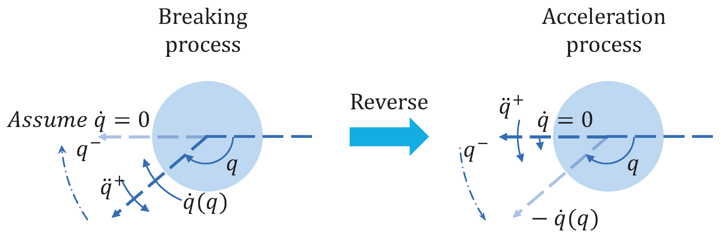
Wang et al. [27] used a two-stage controller to solve the constraint problem. However, the upper and lower bounds of joint velocities are not constants relative to the joint position, because when the joint position increases at its maximum velocity, the joint velocity cannot suddenly become zero when it reaches the upper limit of the joint position. Therefore, it is essential to derive the upper and lower bounds of the joint velocity at different joint positions. The limit of q ˙ at position q is deduced using reverse thinking. At the lower bound of the joint angle, one considers starting from zero with the maximum absolute angular acceleration | q ¨ + | to obtain the curve of the velocity as a function of the joint angle, representing the lower limit ofthe velocity (Figure 6).
1 2 q ¨ + t 2 = q q q ˙ max { q ˙ , q ¨ + t }
Upon the elimination of the time variable t from the given inequality, a resulting expression is obtained as follows:
q ˙ max { q ˙ , 2     | q ¨ + | .     | q q | }
where . denotes element-wise multiplication.
The upper bound expression for q can be derived in a similar manner, and it is presented as Equation (16):
q ˙ min { q ˙ + , 2     | q ¨ | .     | q + q | }

3.3. Demonstration of the IBVS Controller Design Using the Proposed Framework

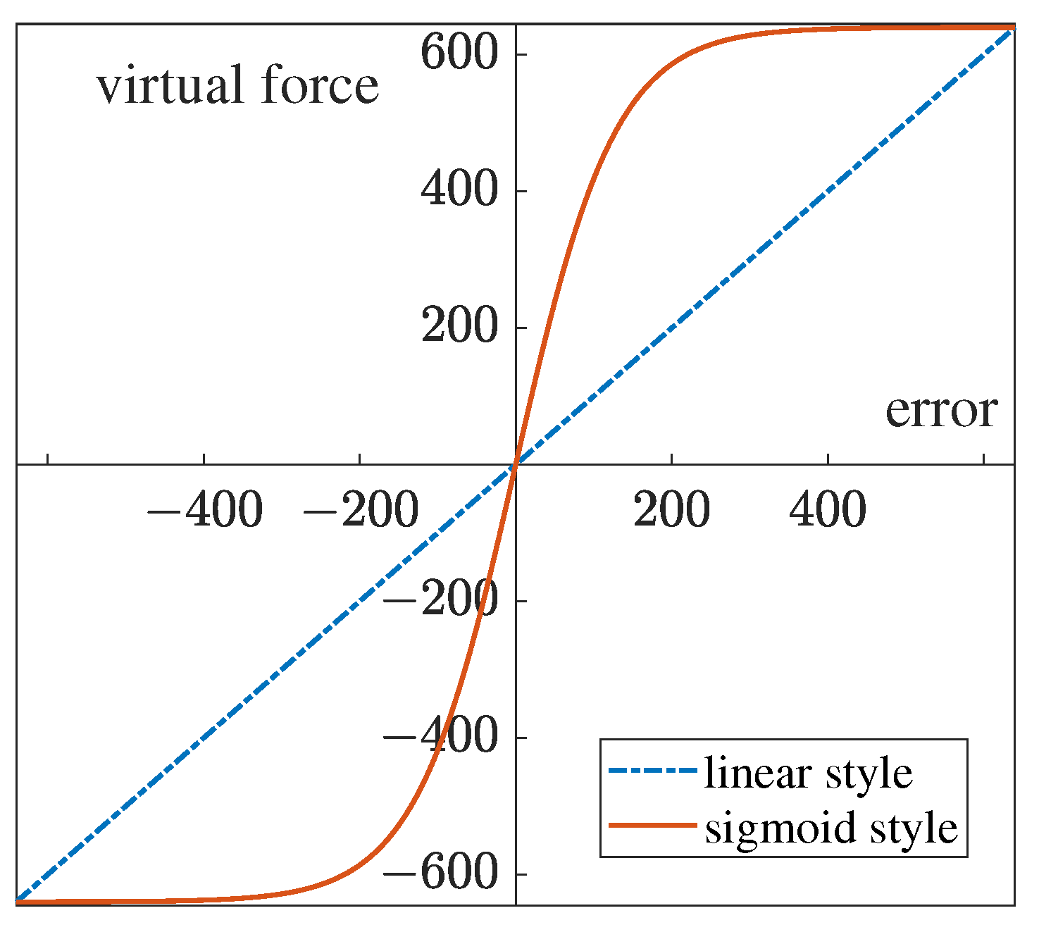
The impedance controller was defined as shown in Equation (7). However, as the error e becomes small, the value of f v also becomes too small, resulting in a slow convergence rate in the final stages. Conversely, when the error e is large, f v becomes overly large, leading to divergence in the discrete controller. To tackle this challenge, a sigmoid-style function is employed to map the error into a suitable range.
First, the error is mapped to the range [ 0 , 10 ] using Equation (17):
e m a p = 10     e p i c t u r e _ s i z e
where p i c t u r e _ s i z e denotes the number of pixels on the longer side of the image, representing the maximum error. e m a p stands for the mapped error. The range of [0, 10] is a hyperparameter. As can be seen from the formula, it serves as a scaling factor for the sigmoid function. The larger this value is, the stronger the amplification effect of the virtual force on small errors, which may also lead to oscillation near zero errors. Conversely, the smaller this value is, the less sensitive it is to small errors. Subsequently, the sigmoid-sytle function (Equation (18)) is utilized to generate virtual forces:
f v = ( 1 1 + exp ( e m a p )     2 1 )     p i c t u r e _ s i z e
Figure 7 illustrates the differences between the linear-style model and the sigmoid-style model. As the error becomes very small, the sigmoid-style model can amplify the virtual force and exhibits saturation when the error is large.
In the context of the admittance control module, the external force is conceptualized as a virtual joint torque. This torque is generated by the impedance controller and is propagated as a virtual force. We eliminated the spring from the mass–spring–damper system, and the dynamic description is as follows:
M q ¨ + C q ˙ = τ v
where M and C are diagonal matrices.
Let ξ = q ˙ . Rewrite Equation (19) as a state equation:
ξ ˙ = M 1 C ξ + M 1 τ v .
Let A = M 1 C , B = M 1 . Both A and B are also diagonal matrices.
Equation (20) can be discretized using the forward Euler method:
ξ ( k + 1 ) = ξ ( k ) + ( A ξ ( k ) + B τ v ( k ) ) d t
where d t is the control period. Then, the total controller is
q ˙ ( k ) = Ω v ( q ˙ ( k 1 ) + Ω a ( A q ˙ ( k 1 ) + B τ v ( k 1 ) ) d t ) q ( k + 1 ) = q ( k ) + q ˙ ( k ) d t .
where q ( k ) denotes the current angle of the joints, which can be obtained from the robot sensors or data of the simulation environment; Ω v ( · ) is the limitation of the joint velocity using Equations (15) and (16); and Ω a ( · ) is the limitation of the joint acceleration.

4. Results and Discussion

In this study, an experiment was conducted using the VREP simulation environment to validate the proposed method. The UR5 robotic was utilized for this experiment. The D-H parameters for the UR5 are provided in Table 1.
The physical constraints of the manipulator are shown in Table 2.
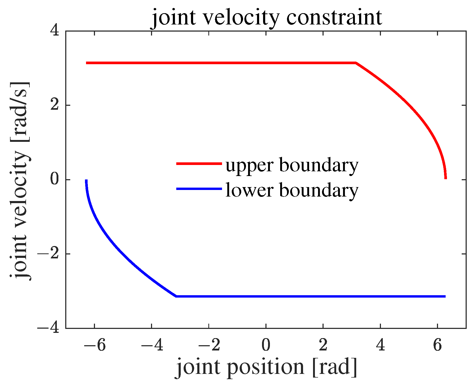
The improved physical constraint boundary function is depicted in Figure 8. If the joint velocity is beyond the boundary, there must be a physical constraint that is not satisfied at some times.
A visual sensor was mounted at the end-effector of the UR5. The parameters of the camera are shown in Table 3.
The neural network control algorithm proposed in [23] was reproduced for a comparison. This method does not include the inverse of the Jacobian matrix and does not have a singularity problem. The controller in [23] is described as follows:
q ˙ = P Ω ( κ 1 J T ( s s d ) κ 2 J T 0 t ( s s d ) d t )
where ω is the velocity vector of the joint, and P Ω ( · ) projects the output within the physical constraints. κ 1 and κ 2 are the parameters that need to be adjusted. The physical constraints in [23] are described in Equation (24). Therefore, there is another parameter k in the physical constraints.
max { q ˙ , k     ( q q ) } q ˙ min { q ˙ + , k     ( q + q ) }
Hence, to meet the physical constraints, we drew a line between ( 3.137 , 3.142 ) and ( 6.287 , 0 ) in Figure 8 and obtained the parameter k = 1 . Table 4 describes the adjusted parameters in the neural network method.
The final parameters applied to the proposed algorithm are shown in Table 5.
The control period was dt = 0.05 s in order to fit the real environment, which satisfies most real-time image frame rates. To verify the performance of the algorithm under different tasks, after the parameters were properly adjusted, it was maintained constant across all experiments.

4.1. Convergence Performance Simulation

Convergence performance is one of the most important indexes used to evaluate a visual servoing algorithm. We set a static object and designated the target points as ( 80 , 80 ) and ( 320 , 240 ) . The former point is near the corner of the image, which easily loses sight of the object. The latter is at the center of the image, which is near the major target point of the visual servoing tasks. The experimental environment is shown in Figure 3.
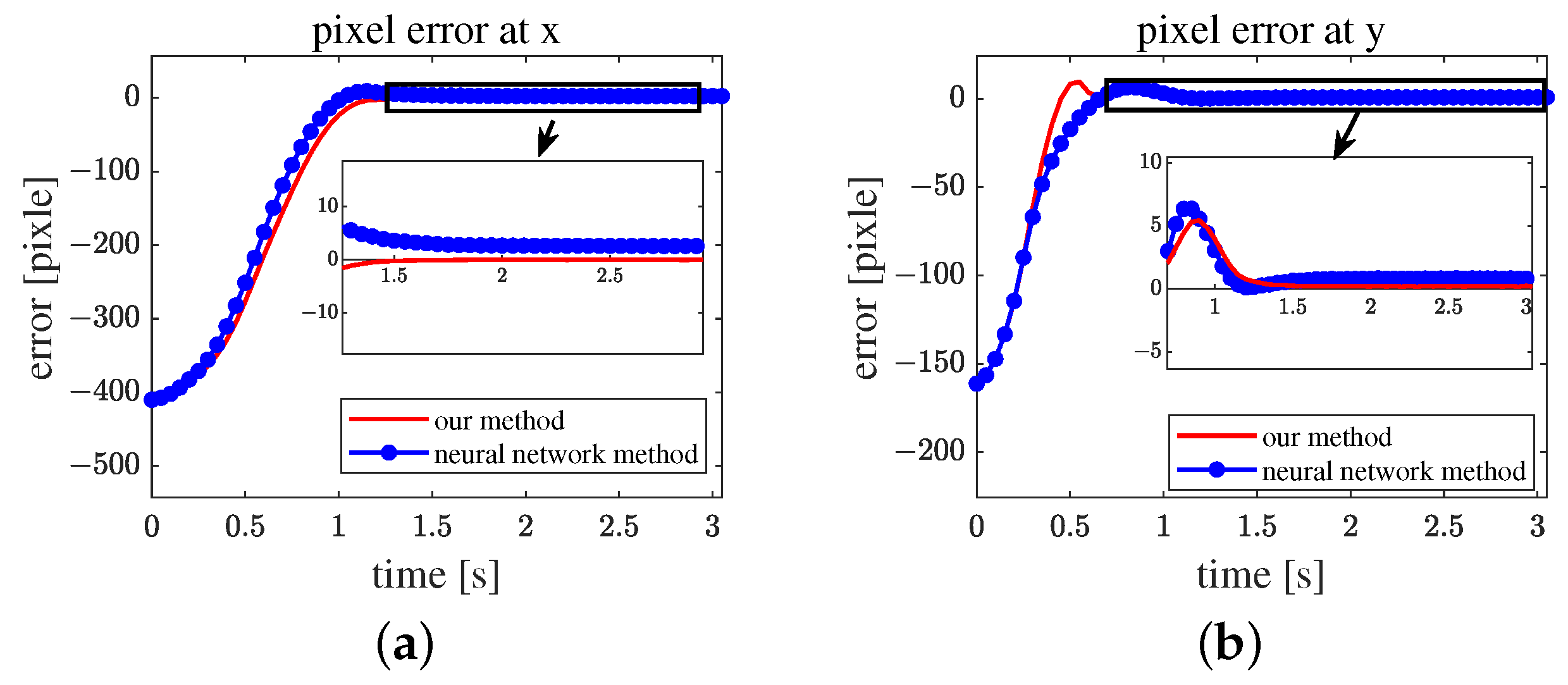
The neural network method needs a long time to converge because it has an integral. When the error becomes too small, the neural network controller needs a long time to overcome the accumulated error. The proposed sigmoid-style impedance module enhances the influence of error on the controller when the error is small. Without the integration of errors, the proposed algorithm converges close to zero. The final error in the pixel of the proposed algorithm is (0.01, 0.2), and that of the neural network method is (2.6, 0.8), as shown in Figure 9.
Figure 10 displays the curve of the joint velocity. Both algorithms speed up with the maximum joint acceleration at the beginning and then decelerate to zero. At approximately 0.4 s, the acceleration of the neural network method decreased, as shown in Figure 10b–d, mainly because the error is very small. Hence, velocity was mainly determined through the integral portion in Equation (23). The proposed algorithm could keep a rapid response when the error was small.
In many cases, the target point of the visual servoing task is located near the center of the image; thus, the center of the image ( 320 , 240 ) is representative.
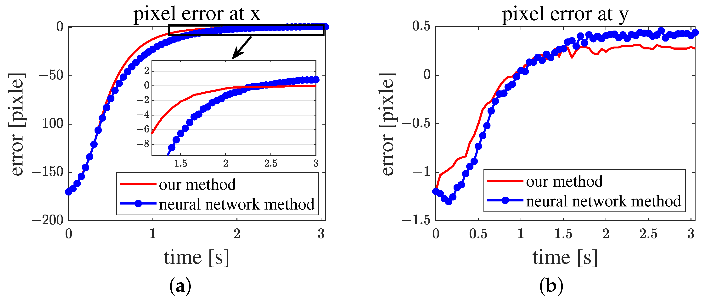
Figure 11 shows that the proposed algorithm has a fast convergence rate, although the convergence rate when the servo is near ( 80 , 80 ) is equivalent. As mentioned before, the neural network method can converge to a narrow range. However, it needs a long time to converge to zero.
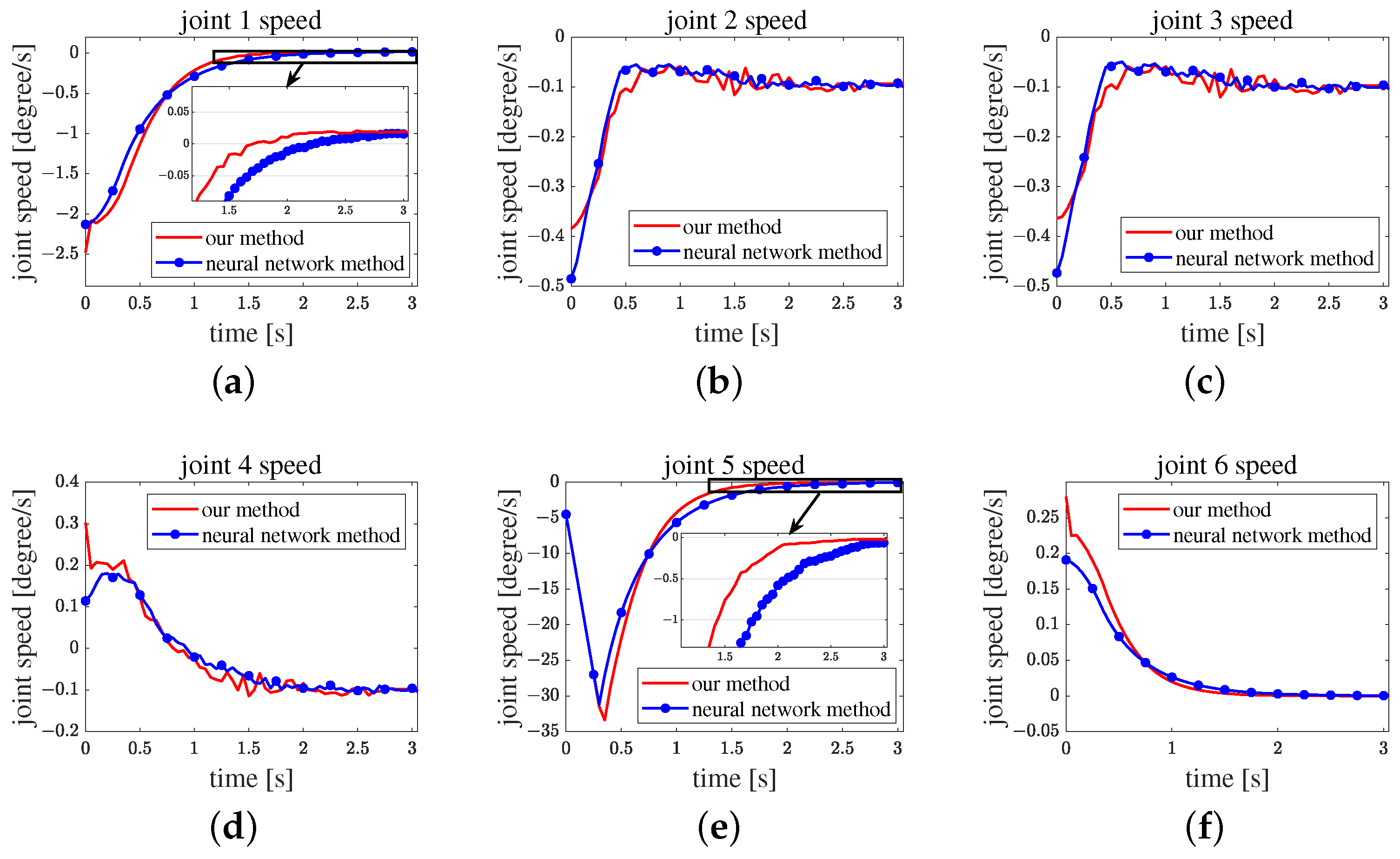
Figure 12 shows the velocity curve of each joint. The velocities in (b), (c), and (d) of this figure are near zero, which means that these joints are near the target joint angles. The curve of velocity in (a), (e), and (f) show that the proposed algorithm always exhibits high acceleration. Thus, the proposed algorithm enhances the performance of the manipulator.

4.2. Object Tracking Task Simulation

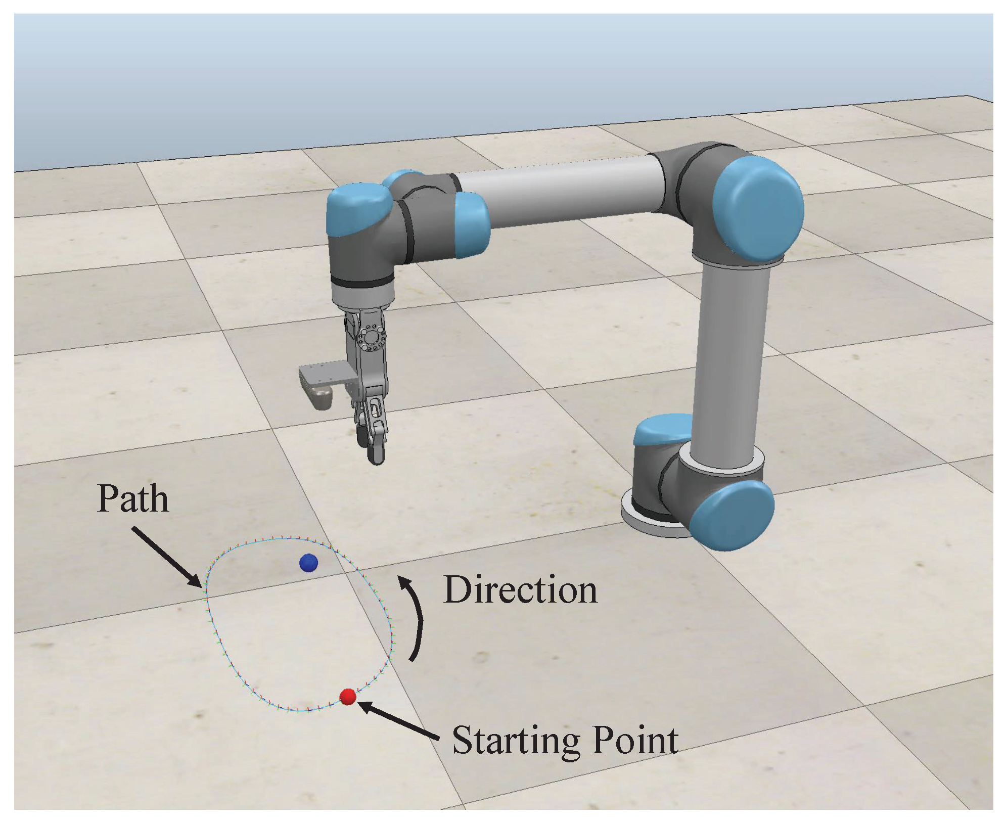
Object tracking is another widely used application in dynamic object grasping and photography. We set up the environment as shown in Figure 13.
We built a curved path and let the blue ball move along it at a speed of 0.1 m/s. This movement can reflect the response performance when the error changes in different directions.
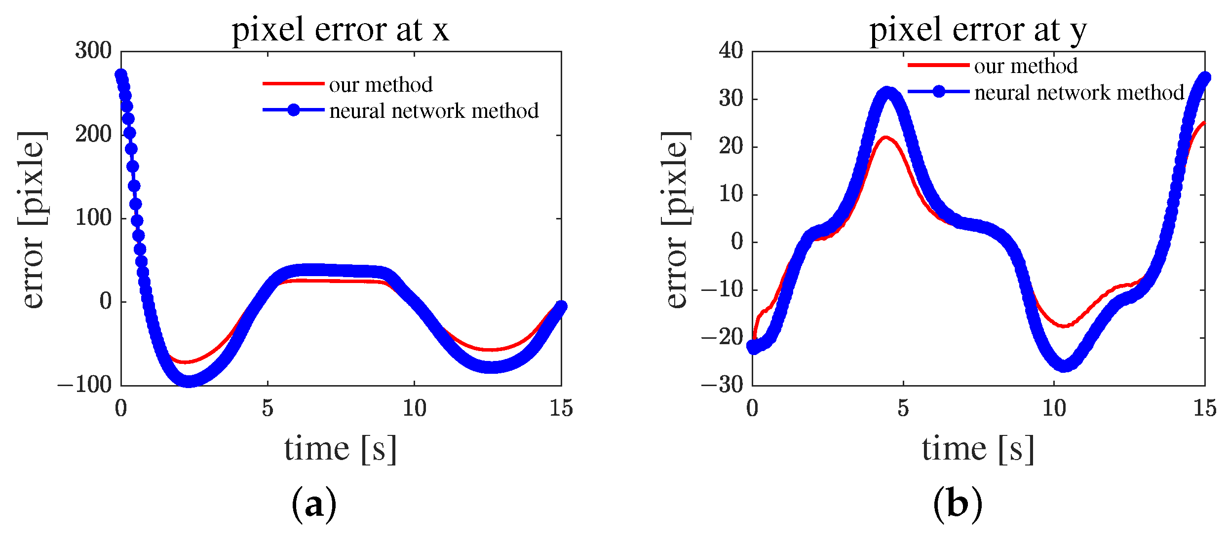
Figure 14a shows the pixel error on the x-axis, and (b) shows the pixel error on the y-axis. Both systems can track the target within a margin of error of 0.35 s. Compared with the method in [23], the proposed algorithm shows a smaller pixel error both on the x- and y-axes.
Figure 15 shows that the proposed algorithm can speed up to a higher velocity, which means that it can catch the target faster. The proposed algorithm also has a faster response to velocity, which is especially obvious in Figure 15a.

4.3. Physical Experiment

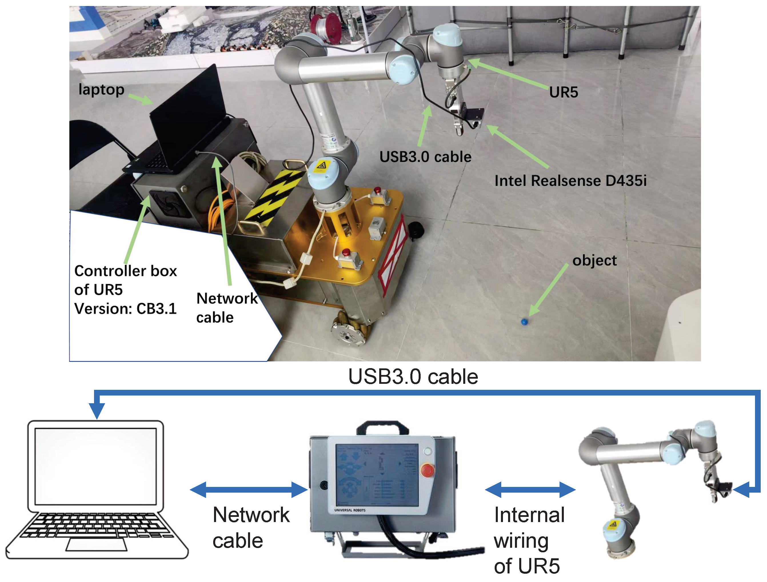
To validate the feasibility of the proposed algorithm in practical applications, we replicated the simulation environment at a 1:1 scale. However, because of the difficulty of maintaining a fixed trajectory for a small ball to follow a constant speed in a real-world environment, we conducted only static servo experiments. Using a UR5 with a body manufactured in 2015 (The manufacturer is Universal Robots USA, Inc 27175 Haggerty Road, Suite 16048377 Novi, MI, USA, We introduced the UR5 in 2017 by purchasing a third party mobile robot equipped with UR5 in Shenzhen, China) and a control system upgraded to version CB3.1 (Figure 16), we controlled the UR5 by sending velocity commands through TCP/IP protocol communication using a Python (version 3.10.12) script running on a laptop. During actual operation, the maximum control frequency of the UR5 in this control mode was 10 Hz, due to the reporting frequency of the state of UR5 being 10Hz. Therefore, we adjusted the control cycle of the controller to 0.1 s.
The notebook configuration adopted in this study was as follows: an Intel 9th Generation Core i7, 16 GB DDR4, and an NVIDIA GeForce RTX 2060 GPU. With this configuration, the controller’s computation time ranged from 3 ms to 5 ms, which is significantly shorter than the control cycle of 100 ms.
The parameters of the real camera can be obtained from the Intel RealSense API. Table 6 shows the detailed parameters.
In this study, the traditional PID control was also incorporated into the comparison. The design of the PID controller is depicted in the following figure (Figure 17).
Here, K p , K i , and K d , respectively, represent the proportional, integral, and derivative coefficients. J is the pseudoinverse of the Jacobian matrix.
The parameters of the controller used in the physical experiment are shown in Table 7.
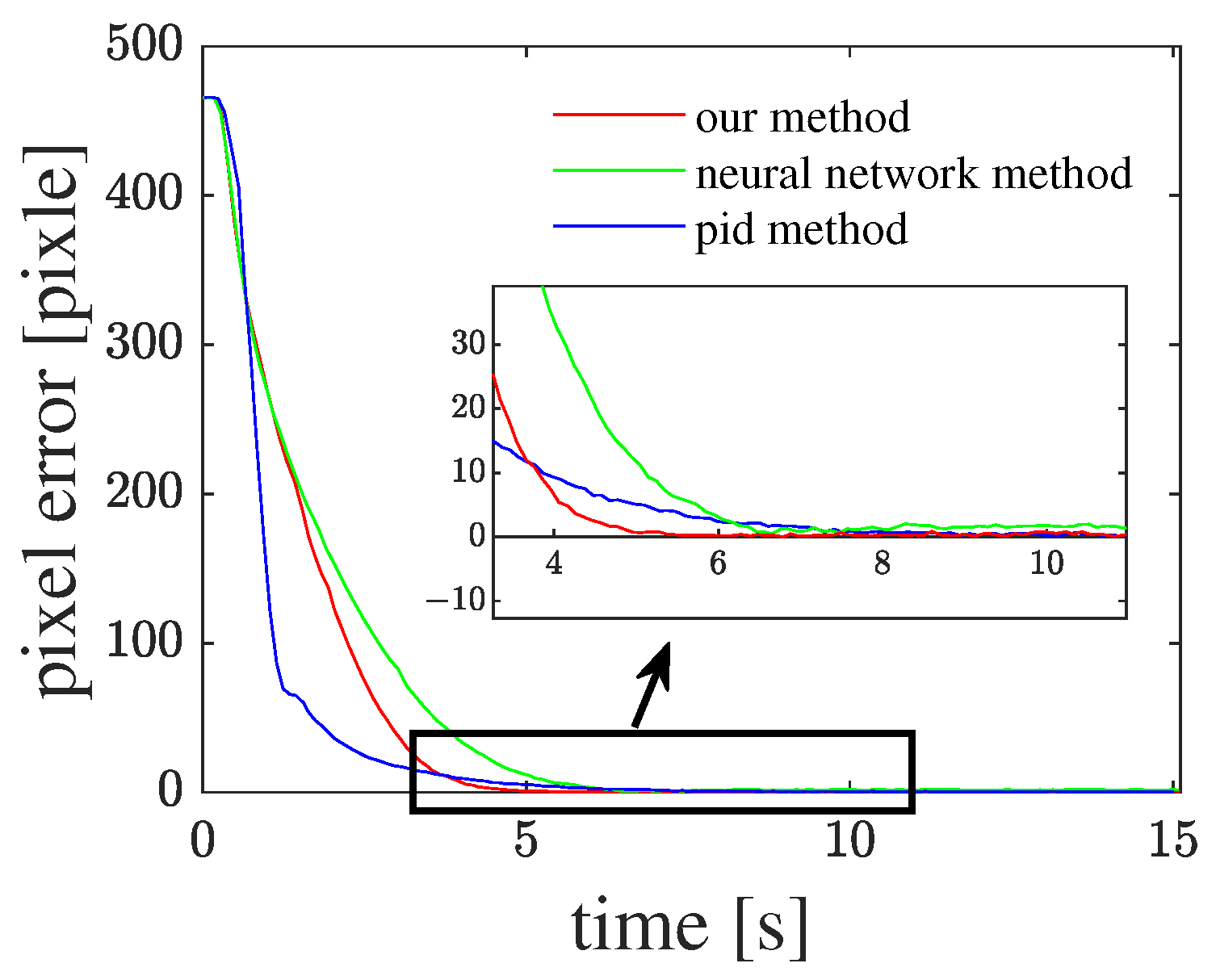
Our proposed algorithm shows superiority over the compared method, as it converged approximately 2 s earlier than others (Figure 18). From the error curve, it can be observed that, initially, the convergence speed of the proposed algorithm is not the fastest. However, in the final 10 pixels, the convergence speed of the proposed algorithm surpasses those of other comparative algorithms.
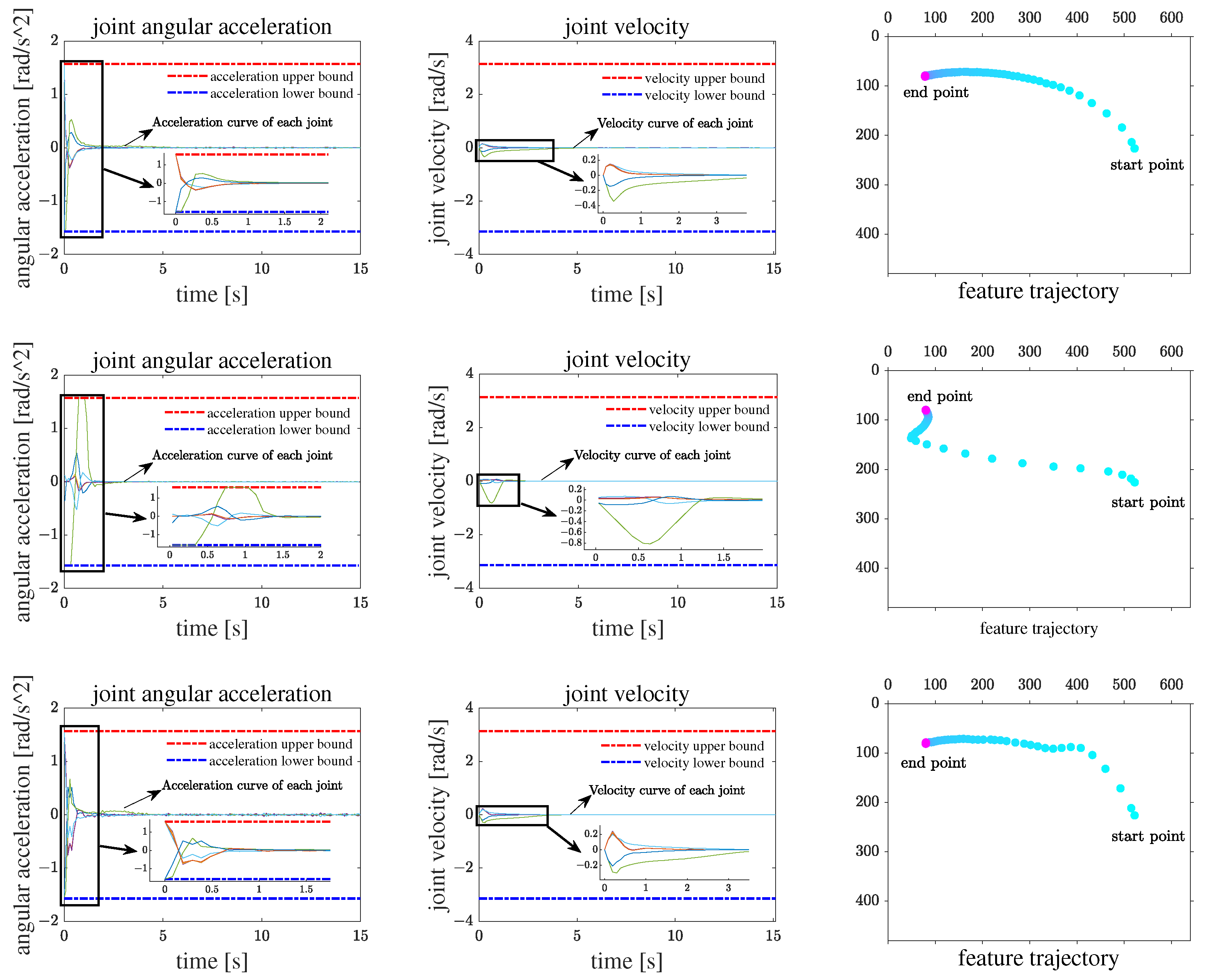
The first column in Figure 19 shows the curves of the joint velocity in, it can be seen that the PID controller using the pseudoinverse algorithm tends to concentrate the joint motion on a certain joint, causing the acceleration of that joint to quickly reach its upper limit, thereby affecting the convergence speed of the error. However, in using the transposition method, it can be seen that, initially, all joints reach the maximum acceleration, and in the subsequent stage, the acceleration of all joints does not exceed the joint’s acceleration limit, and the speed distribution is relatively uniform. In comparison, this method is more conducive to the performance of the robotic arm.
The third column in Figure 19 shows the trajectory of featrue point s at each sample time, it can be observed that the transposition method and inverse method exhibit different directions of fastest convergence. According to our understanding of the proposed framework, when the virtual power is transformed into the joint space, the inverse method guides the joint motion by calculating the velocity using kinematics, whereas the transposition method guides the joint motion by generating the target velocity through the admittance control based on virtual torque. In assuming that the propagated virtual power in both algorithms is the same, there is an inverse relationship between the joint velocity obtained by the inverse method and the virtual torque derived from the transposition method. Thus, it can be inferred that in the direction where the inverse method converges rapidly, the transposition method converges slower, whereas in the direction where the inverse method converges slowly, the transposition method exhibits a faster convergence.
Compared with the two transposed methods, it can be seen that the proposed method has a more aggressive speed adjustment and faster convergence rate when the error is small, which indicates the effectiveness of the proposed architecture for a visual servo controller design. Moreover, from the acceleration curve, it can be seen that in the first 0.1 s, the reference method experiences a maximum acceleration due to excessive output caused by a large error, which reaches the physical acceleration limit of the joint. Thanks to the design of the impedance controller, the algorithm based on the proposed framework can limit the output to prevent divergence in discrete systems when there is a large error, while amplifying the impact of errors on joints when there is a small error, thereby achieving a faster convergence speed in small errors. Furthermore, from the speed curve, it can be seen that while the joint with the fastest speed has almost the same speed as the reference method with our proposed method, the other joints rotate faster with our proposed method than with the reference method. As shown in the trajectory image on the right, our solution has a faster convergence speed while maintaining an equivalent overshoot compared to the reference method.
5. Conclusions

This paper proposes a new image-based visual servoing framework for redundant manipulators, which use Jacobian transport instead of inversion. The framework can effectively avoid the singular value of the Jacobian matrix. For physical constraints, we elucidated the relationship between joint acceleration and the boundary function of joint velocities on joint angles, which can set the joint acceleration directly. The dynamic and static experiments used the same configuration, which ensured that the system could move to any point in the picture. The results show that our method performs well for dynamic tracking and lower amplitude fluctuations when the target arrives. The physical experiment verified the feasibility of our algorithm. To meet the end-velocity requirements of the end-effector, the inverse Jacobian method may cause joints in singular points to operate at high speeds, seriously affecting the safe operation of the manipulator. However, because virtual force propagation is used in the proposed method, joints in singular points are not subjected to (or receive minimal) force traction, resulting in joint speeds approaching zero. Based on this feature, we will further use this method as a downstream algorithm for reinforcement learning to operate a manipulator for grasping.

Author Contributions

Conceptualization, Q.Y. and W.W.; methodology, Q.Y.; software, Q.Y.; validation, W.W., D.W. and Y.G.; formal analysis, Y.L.; resources, W.W.; writing—original draft preparation, Q.Y.; writing—review and editing, Y.L.; visualization, Y.G.; supervision, W.W.; project administration, W.W.; funding acquisition, W.W. All authors have read and agreed to the published version of the manuscript.

Funding

This research was funded by the Science and Technology Planning Project of Guangdong under grants 2015B010919007, 2016A04040312, 2017B090901043, 2019A050520001, 2022A1515110566, and 2023A1515011574.

Data Availability Statement

Data presented in this study are available upon request from the corresponding author.

Conflicts of Interest

The authors declare no conflicts of interest.

Abbreviations

The following abbreviations are used in this manuscript:
IBVSImage-Based Visual Servo;
PBVSPosition-Based Visual Servo;
HVSHybrid Visual Servo;
CTMComputed Torque Method;
RRTRapidly Exploring Random Tree;
LPVLinear Parameter-Varying;
QPQuadratic Programming.

References

  1. Lin, J.; Miao, Z.; Zhong, H.; Peng, W.; Wang, Y.; Fierro, R. Adaptive image-based leader–follower formation control of mobile robots with visibility constraints. IEEE Trans. Ind. Electron. 2020, 68, 6010–6019. [Google Scholar] [CrossRef]
  2. Miao, Z.; Zhong, H.; Lin, J.; Wang, Y.; Chen, Y.; Fierro, R. Vision-based formation control of mobile robots with FOV constraints and unknown feature depth. IEEE Trans. Control Syst. Technol. 2020, 29, 2231–2238. [Google Scholar] [CrossRef]
  3. Qi, R.; Tang, Y.; Zhang, K. An optimal visual servo trajectory planning method for manipulators based on system nondeterministic model. Robotica 2022, 40, 1665–1681. [Google Scholar] [CrossRef]
  4. Thomas, J.; Loianno, G.; Sreenath, K.; Kumar, V. Toward image based visual servoing for aerial grasping and perching. In Proceedings of the IEEE International Conference on Robotics and Automation (ICRA), Hong Kong, China, 31 May–5 June 2014; pp. 2113–2118. [Google Scholar] [CrossRef]
  5. Song, J.B. Object tracking and visual servoing using features computed from local feature descriptor. In Proceedings of the IEEE international Conference on Control, Automation and Systems (ICCAS), Gyeonggi-do, Republic of Korea, 27–30 October 2010; pp. 1044–1048. [Google Scholar] [CrossRef]
  6. Rosenberger, P.; Cosgun, A.; Newbury, R.; Kwan, J.; Ortenzi, V.; Corke, P.; Grafinger, M. Object-independent human-to-robot handovers using real time robotic vision. IEEE Robot. Autom. Lett. 2020, 6, 17–23. [Google Scholar] [CrossRef]
  7. Pan, W.; Lyu, M.; Hwang, K.S.; Ju, M.Y.; Shi, H. A neuro-fuzzy visual servoing controller for an articulated manipulator. IEEE Access 2018, 6, 3346–3357. [Google Scholar] [CrossRef]
  8. Siradjuddin, I.; Behera, L.; McGinnity, T.M.; Coleman, S. Image-based visual servoing of a 7-DOF robot manipulator using an adaptive distributed fuzzy PD controller. IEEE-ASME Trans. Mechatron. 2013, 19, 512–523. [Google Scholar] [CrossRef]
  9. Shi, H.; Chen, J.; Pan, W.; Hwang, K.S.; Cho, Y.Y. Collision avoidance for redundant robots in position-based visual servoing. IEEE Syst. J. 2018, 13, 3479–3489. [Google Scholar] [CrossRef]
  10. Noh, S.; Park, C.; Park, J. Position-Based Visual Servoing of Multiple Robotic Manipulators: Verification in Gazebo Simulator. In Proceedings of the IEEE international Conference on Information and Communication Technology Convergence (ICTC), Jeju, Republic of Korea, 21–23 October 2020; pp. 843–846. [Google Scholar] [CrossRef]
  11. He, Z.; Wu, C.; Zhang, S.; Zhao, X. Moment-based 2.5-D visual servoing for textureless planar part grasping. IEEE Trans. Ind. Electron. 2018, 66, 7821–7830. [Google Scholar] [CrossRef]
  12. Malis, E.; Chaumette, F.; Boudet, S. 2 1/2 D visual servoing. IEEE Trans. Robot. Autom. 1999, 15, 238–250. [Google Scholar] [CrossRef]
  13. Keshmiri, M.; Xie, W.F.; Mohebbi, A. Augmented image-based visual servoing of a manipulator using acceleration command. IEEE Trans. Ind. Electron. 2014, 61, 5444–5452. [Google Scholar] [CrossRef]
  14. Tsai, D.; Dansereau, D.G.; Peynot, T.; Corke, P. Image-based visual servoing with light field cameras. IEEE Robot. Autom. Lett. 2017, 2, 912–919. [Google Scholar] [CrossRef]
  15. Wang, H.; Yang, B.; Wang, J.; Liang, X.; Chen, W.; Liu, Y.H. Adaptive visual servoing of contour features. IEEE-ASME Trans. Mechatron. 2018, 23, 811–822. [Google Scholar] [CrossRef]
  16. Dong, G.; Zhu, Z.H. Kinematics-based incremental visual servo for robotic capture of non-cooperative target. Robot. Auton. Syst. 2019, 112, 221–228. [Google Scholar] [CrossRef]
  17. Chaudhuri, S.; Saha, R.; Chatterjee, A.; Mookherjee, S.; Sanyal, D. Development of a motion sensing system based on visual servoing of an eye-in-hand electrohydraulic parallel manipulator. IEEE Syst. J. 2020, 20, 8108–8116. [Google Scholar] [CrossRef]
  18. Wang, R.; Zhang, X.; Fang, Y.; Li, B. Virtual-Goal-Guided RRT for Visual Servoing of Mobile Robots With FOV Constraint. IEEE Trans. Syst. Man Cybern. Syst. 2022, 52, 2073–2083. [Google Scholar] [CrossRef]
  19. Kazemi, M.; Gupta, K.K.; Mehrandezh, M. Randomized Kinodynamic Planning for Robust Visual Servoing. IEEE Trans. Robot. 2013, 29, 1197–1211. [Google Scholar] [CrossRef]
  20. Gong, Z.; Tao, B.; Qiu, C.; Yin, Z.; Ding, H. Trajectory Planning With Shortest Path for Modified Uncalibrated Visual Servoing Based on Projective Homography. IEEE Trans. Autom. Sci. Eng. 2020, 17, 1076–1083. [Google Scholar] [CrossRef]
  21. Hajiloo, A.; Keshmiri, M.; Xie, W.F.; Wang, T.T. Robust online model predictive control for a constrained image-based visual servoing. IEEE Trans. Ind. Electron. 2015, 63, 2242–2250. [Google Scholar] [CrossRef]
  22. Jin, L.; Li, S.; La, H.M.; Luo, X. Manipulability optimization of redundant manipulators using dynamic neural networks. IEEE Trans. Ind. Electron. 2017, 64, 4710–4720. [Google Scholar] [CrossRef]
  23. Zhang, Y.; Li, S. A neural controller for image-based visual servoing of manipulators with physical constraints. IEEE Trans. Neural Netw. Learn. Syst. 2018, 29, 5419–5429. [Google Scholar] [CrossRef]
  24. Zhang, Y.; Wang, J.; Xia, Y. A dual neural network for redundancy resolution of kinematically redundant manipulators subject to joint limits and joint velocity limits. IEEE Trans. Neural Netw. 2003, 14, 658–667. [Google Scholar] [CrossRef] [PubMed]
  25. Kebria, P.M.; Al-Wais, S.; Abdi, H.; Nahavandi, S. Kinematic and dynamic modelling of UR5 manipulator. In Proceedings of the IEEE International Conference on Systems, Man, and Cybernetics (SMC), Budapest, Hungary, 9–12 October 2016; pp. 4229–4234. [Google Scholar] [CrossRef]
  26. Corke, P.I.; Khatib, O. Robotics, Vision and Control: Fundamental Algorithms in MATLAB, 2nd ed.; Springer: Cham, Switzerland, 2011; pp. 63–68. [Google Scholar]
  27. Wang, R.; Zhang, X.; Fang, Y. Visual tracking of mobile robots with both velocity and acceleration saturation constraints. Mech. Syst. Signal Process. 2021, 150, 107274. [Google Scholar] [CrossRef]
  28. Universal Robots-DH Parameters for Calculations of Kinematics and Dynamics. 2022. Available online: https://www.universal-robots.com/articles/ur/application-installation/dh-parameters-for-calculations-of-kinematics-and-dynamics/ (accessed on 9 March 2022).
Figure 1. D-H coordinate definition.
Actuators 13 00181 g001
Figure 2. The definition of the coordinate systems for modeling a camera.
Actuators 13 00181 g002
Figure 3. Eye-in-hand system structure.
Actuators 13 00181 g003
Figure 4. The general framework.
Actuators 13 00181 g004
Figure 5. Proposed IBVS framework.
Actuators 13 00181 g005
Figure 6. Description of the reasoning process of reverse thinking.
Actuators 13 00181 g006
Figure 7. Schematic of linear-style and sigmoid-style impedance modules.
Actuators 13 00181 g007
Figure 8. The proposed joint velocity constraint on the joint angle.
Actuators 13 00181 g008
Figure 9. The curve of the pixel error when the feature point s moves to (80, 80): (a) error along the x-axis; (b) error along the y-axis.
Actuators 13 00181 g009
Figure 10. Joint speed in the move to (80, 80): (a) base joint; (b) shoulder joint; (c) elbow joint; (d) wrist_1 joint; (e) wrist_2 joint; (f) wrist_3 joint.
Actuators 13 00181 g010
Figure 11. The curve of the pixel error when the servo moves to (320, 240): (a) error along the x-axis. (b) error along the y-axis.
Actuators 13 00181 g011
Figure 12. Joint speed in the move to (320, 240): (a) angular velocity of base joint; (b) angular velocity of the shoulder joint; (c) angular velocity of the elbow joint; (d) angular velocity of wrist_1 joint; (e) angular velocity of wrist_2 joint; (f) angular velocity of wrist_3 joint.
Actuators 13 00181 g012
Figure 13. Circle path of visual servoing environment.
Actuators 13 00181 g013
Figure 14. The curve of the pixel error when the feature point s moves to (320, 240) with a dynamic object: (a) error along the x-axis; (b) error along the y-axis.
Actuators 13 00181 g014
Figure 15. The curve of the joint speed when the feature point s moves to (320, 240) with a dynamic object: (a) base joint; (b) shoulder joint; (c) elbow joint; (d) wrist_1 joint; (e) wrist_2 joint; (f) wrist_3 joint.
Actuators 13 00181 g015aActuators 13 00181 g015b
Figure 16. The environment of the real experiment.
Actuators 13 00181 g016
Figure 17. The traditional PID controller.
Actuators 13 00181 g017
Figure 18. The curve of the pixel error when the moves to (80, 80).
Actuators 13 00181 g018
Figure 19. (First row): neural network method. (Second row): PID controller. (Third row): proposed algorithm.
Actuators 13 00181 g019
Table 1. UR5 D-H parameters [28].
Joint NumberJoint Name α i (rad) a i (m) d i (m) θ i (rad)
1base π / 2 00.089159 θ 1
2shoulder0−0.4250 θ 2
3elbow0−0.392250 θ 3
4wrist_1 π / 2 00.10915 θ 4
5wrist_2 π / 2 00.09465 θ 5
6wrist_3000.0823 θ 6
Table 2. Limitation of UR5.
UR5 ParametersLimitationUnit
Joint angle [ 2 π , 2 π ] rad
Joint velocity [ π , π ] rad/s
Joint acceleration [ π / 2 , π / 2 ] rad/s2
Table 3. The configuration of the camera in VREP.
Camera ParameterValueUnit
Width640pixel
Height480pixel
f0.01meter
u 0 319.4716pixel
v 0 239.2442pixel
a x 45,668.2625pixels per meter
a y 45,669.5772pixels per meter
Z10meter
Table 4. Adjusted parameters of neural network controller.
ParametersValue
k 1 0.000009
k 2 0.0000001
k1
Table 5. Tested parameters of proposed algorithm.
ParametersValue
M diag(16,000, 16,000, 16,000, 16,000, 16,000, 16,000)
C diag(368,000, 368,000, 368,000, 368,000, 368,000, 368,000)
Table 6. The parameters of realsense D435i.
ParameterValueUnit
Width640pixel
Height480pixel
f0.604meter
u 0 321.294pixel
v 0 244.492pixel
a x 406.743pixels per meter
a y 883.042pixels per meter
Z10meter
Table 7. Adjusted parameters of physical experiment.
ParametersValueBelongs to
k 1 0.000002neural network controller
k 2 0.000000004neural network controller
k1neural network controller
K p 0.7PID controller
K i 0PID controller
K d 0.0001PID controller
M55,000proposed algorithm
C790,000proposed algorithm
Disclaimer/Publisher’s Note: The statements, opinions and data contained in all publications are solely those of the individual author(s) and contributor(s) and not of MDPI and/or the editor(s). MDPI and/or the editor(s) disclaim responsibility for any injury to people or property resulting from any ideas, methods, instructions or products referred to in the content.