Article

Synchronization Control with Dynamics Compensation for Three-Axis Parallel Motion Platform

1
State Key Laboratory of Precision Electronic Manufacturing Technology and Equipment, Guangdong University of Technology, Guangzhou 510006, China
2
Key Laboratory of Intelligent Inspection and Manufacturing IoT of Ministry of Education, Guangdong University of Technology, Guangzhou 510006, China
*
Author to whom correspondence should be addressed.
Actuators 2024, 13(5), 166; https://doi.org/10.3390/act13050166
Submission received: 3 April 2024 / Revised: 24 April 2024 / Accepted: 26 April 2024 / Published: 1 May 2024
(This article belongs to the Section Actuators for Manufacturing Systems)

Abstract

:
The three-axis parallel motion platform (TAPMP) with a common stator has low motion inertia, enabling highly precise and high-speed motion over a large range of strokes. The primary challenge faced by the TAPMP lies in the mutual pulling exerted between the common stator motors during motion. The driving forces generated by the motors are closely associated with their synchronization motion, a connection often overlooked in the design of existing controllers. To address this issue, this paper presents a novel synchronization controller with dynamics compensation (SC–DC) to achieve motion synchronization between the three motors, ultimately enhancing the platform’s tracking accuracy in task space. In this SC–DC method, the synchronization error of the common stator motors is introduced to represent the synchronized motion relationship between adjacent motors, and a dynamic feedforward control is adopted to compensate for the motor’s driving force. The stability of the proposed controller is analyzed using Lyapunov theory, demonstrating the convergence of both the tracking error and synchronization error. Trajectory tracking simulations and experimental studies are conducted on the TAPMP. The results show that, compared to the augmented proportional-derivative controller with dynamic compensation, the proposed controller significantly reduces both the MAE of the tracking error and synchronization error on the q1 motor by 71.88% and 73.02%, respectively, demonstrating its performance advantages in trajectory tracking and synchronization.

1. Introduction

For a three-axis parallel motion platform, precision motion control can be achieved through the coordinated operation of joint motors. This type of platform features lower motion inertia and higher control precision, flexibility, and dynamic performance, enabling the realization of complex three-degrees-of-freedom motion trajectories [1,2]. Therefore, it finds wide applications in high-end equipment fields such as microelectronics manufacturing, high-speed machine tools, new energy equipment, and robotic operations [3,4,5,6].
Despite the parallel platform offering numerous advantages, it presents certain challenges concerning the mutual pulling and control difficulties among joint motors during motion [7,8]. To overcome these issues, advanced modeling theories and control strategies need to be researched and developed continuously to enhance the system’s motion performance. Currently, many scholars focus on controller design for platform motion control, primarily in both task space [9] and joint space [10]. Considering that the planned motion trajectory is established in task space, the motion error of the platform in task space more accurately reflects the processing accuracy of the workpiece compared to the tracking error in joint space [11]. Therefore, designing a controller in task space can facilitate the development process to be more convenient and flexible. For this reason, Khalilpour et al. [12] analyzed and implemented a cascade control method in task space. This approach employed a force sensor-based sliding mode control for inner-loop regulation and achieved precise measurement of the motion platform position through outer-loop control based on visual sensors. Zi et al. [13] proposed a fuzzy control strategy integrating end-effector pose information to achieve rapid and adaptable trajectory tracking for parallel mechanisms. The proposed method achieved real-time measurement of the end-effector pose by using three automatic target rangefinders. Zhu et al. [14] introduced a disturbance-resistant control method combining a sliding mode control and a disturbance observer. This method measured the angular velocity of the spatial robot base using a gyroscope, improving the robot’s motion accuracy while ensuring positioning overshoot and stability time. Fonseca et al. [15] presented a dual-loop controller considering position and attitude impedance coupling. This method utilized a force sensor to measure the torque information of the motion platform, adjusting the mechanism’s motion trajectory through inner-loop position control and outer-loop admittance control to ensure accuracy and stability in the machining process. Altan et al. [16] proposed a model predictive control method that utilized visual sensor measurements of input–output data to establish linear and nonlinear dynamic models, and employed these models for closed-loop control to achieve precise target tracking. However, the implementation of the aforementioned task space control methods often requires the use of external measuring instruments, such as force sensors [17], gyroscopes [18], and visual sensors [19], to obtain essential motion information for each drive axis. Employing external sensors for measurement will increase the system’s complexity and cost. Additionally, if the data bandwidth of external sensors does not match the system’s control bandwidth, it may lead to data processing delays, subsequently affecting the system’s tracking performance [20,21]. Therefore, despite the issue of motion coupling among the drive chains of parallel platforms, designing control strategies in joint space still presents significant challenges [22,23,24]. Fang et al. [25] thus suggested intensified research to design decoupling controllers suitable for parallel platforms in joint space, aiming to meet the demands of high-speed and high-precision control for such systems.
Hosseini et al. [26] proposed a robust model-free decoupling control method. The proposed method employed time-delay estimation technology to estimate the dynamic inertia parameters of the mechanism, achieving high-speed decoupling and precise tracking of mechanism motion through robust nonlinear proportional-derivative controllers. Feng et al. [27] designed a composite controller to ameliorate the tracking accuracy of motion joints. The controller used an adaptive fuzzy control scheme to suppress external disturbances during motion, achieving model-free decoupling control by calculating torque control to compensate for joint drive forces. Yang et al. [28] developed an adaptive controller combining fuzzy neural networks and approximation functions. The controller utilized fuzzy neural networks to estimate the nonlinear dynamics, including friction models, and suppressed estimation errors occurring during the estimation of dynamic parameters by using a sliding mode-based approximation function. Ultimately, it achieved a stable operation of the mechanism under load variations. Escorcia-Hernandez et al. [29] designed an adaptive robust integral control strategy. This method used B-spline functions to assist neural networks in feedforward compensation for nonlinear dynamics, combining robust integral feedback control considering the filtered tracking error for each joint to achieve high-speed positioning operation of parallel mechanisms with minimal tracking error. Zhang et al. [30] and Yun et al. [31] employed inverse dynamics for compensation to improve trajectory tracking accuracy while maintaining the high dynamic performance of robots. Xie et al. [32] proposed a composite control method that combined dynamic feedforward compensation and input signal velocity planning for a five-degrees-of-freedom parallel mechanism to reduce the tracking errors of driving joints induced by multi-axis coupling and complex input signals. Makarem et al. [33] introduced a dynamic tuning control method based on data-driven techniques. This strategy involved adjusting controller parameters using feedback data from grating encoders to address hysteresis and nonlinearities in ultrasonic motors, achieving precise positioning and model-free control of the system. For the control strategies in joint space, precise control can be achieved by fully utilizing real-time information provided by the encoder feedback. Consequently, decoupling control methods can be effectively employed in real-world scenarios to meet the high-speed motion control of the platform [34,35]. However, the drawbacks of the aforementioned controllers in joint space are apparent. Although the grating encoders of each joint possess high resolution and measurement accuracy, the pulling between the drive joints can significantly affect the control accuracy of each motor. This pulling arises from the interaction of the joint drive forces and the poor synchronous motion performance of each motor, and existing control methods in joint space often overlook the coordination of motion between motors [36,37].
Therefore, the implementation of decoupling controllers in joint space, as well as control strategies based on external sensors in task space, exhibit certain deficiencies, making it challenging for existing control methods to ensure the simultaneous fulfillment of tracking performance and synchronization performance for the three-axis parallel motion platform (TAPMP). Currently, synchronization control methods include parallel control, master–slave control, cross-coupling control, and control methods based on specific control theories. For instance, Zhong et al. [38] proposed a fractional-order feedforward control method based on frequency characteristic adjustment theory to enhance the synchronization performance of a gantry platform. However, most of the existing synchronization control methods are primarily applicable to dual-motor platforms. Considering the three-motor co-axis structure of the TAPMP, this paper proposes a novel synchronization controller with dynamic compensation (SC–DC) in joint space to achieve motion synchronization between the three motors, ultimately enhancing the platform’s tracking accuracy in task space. The proposed controller primarily possesses two significant advantages. Firstly, it is established using information from the platform joint space, eliminating the need for external sensors to enhance the control performance of the TAPMP, thereby reducing cost and demonstrating high applicability. Secondly, compared to the traditional decoupling controllers, the proposed controller introduces a synchronization error of the common stator motors, which accurately represents the synchronization relationship between adjacent motors. Thus, the proposed method can achieve better tracking and synchronization accuracy. Finally, the effectiveness and advancement of the proposed controller are verified through simulation analysis and practical experiments.
To ensure the high accuracy and effective implementation of the proposed SC–DC method, a comprehensive dynamic model is developed, which encompasses the dynamics of the moving platform and auxiliary blocks. Subsequently, according to the motion characteristics of the common stator motors, a synchronization error of the common stator motors is introduced to represent the synchronized motion relationship between adjacent motors. Moreover, the coupling error is defined in an adjacent sequence based on the tracking error and the synchronization error. The proposed SC–DC is formulated to eliminate both coupling and synchronization errors, while compensating for the dynamics of the auxiliary blocks and the driving force of each motor. Utilizing Lyapunov theory, it is verified that the proposed controller can ensure convergence of both the tracking error and synchronization error. Trajectory tracking simulations and experimental studies are conducted on the TAPMP. The results show that, compared to the augmented proportional-derivative controllers with dynamic compensation, the proposed controller significantly reduces the synchronization error and tracking error for each motor, demonstrating its performance advantages in trajectory tracking and synchronization.
The remaining sections of this paper are organized as follows. The structure and kinematic model of the TAPMP are introduced in Section 2. The dynamic modeling of the TAPMP is elaborated in Section 3. The implementation process and stability analysis of the proposed SC–DC are described in Section 4. Simulation results are discussed in Section 5. Experimental validation is conducted in Section 6. Finally, the main research of this paper is summarized in Section 7.

2. Kinematic Modeling of the TAPMP

2.1. Structural Description

The integration of the TAPMP with a parallel platform and direct-drive linear motors enables precise control of the motion trajectory in three degrees of freedom. To ensure the rigidity and reliability of the platform, a symmetrical architectural design is implemented, as illustrated in Figure 1. The TAPMP mainly consists of a guide rail, a left auxiliary block, a moving platform, a middle auxiliary block, a right auxiliary block, three linear motors with a common stator, and a grating ruler. The left, middle, and right auxiliary blocks are concurrently driven by three linear motors with a common stator, enabling accurate position control. The grating ruler possesses a resolution of 100 nm, meeting the precision measurement requirements for the platform’s accurate motion.

2.2. Kinematic Modeling

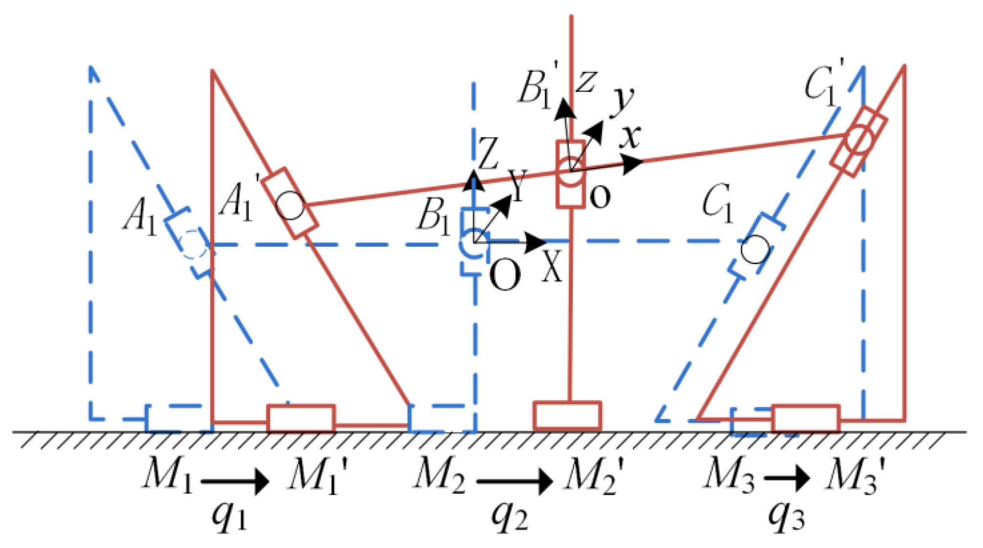
Based on the structural configuration of the designed TAPMP, a kinematic model is formulated, as illustrated in Figure 2. In this representation, the dashed lines (M1, M2, M3) and solid lines (M1′, M2′, M3′) correspondingly denote the initial and final positions of the three motor-driven components. Endpoints A1 and C1 are linked to the left and right auxiliary blocks, respectively, while B1 serves as the central point of the moving platform. The variables  q 1 q 2 , and  q 3  represent the displacement of the three motor-driven components as they move from their initial to final positions.  L 1  signifies the width of the moving platform. Coordinate systems O-XYZ and o-xyz are established, with O and o denoting the midpoints of the moving platform at its initial and final positions, respectively.
According to Figure 2 and utilizing the loop vector method [39], the forward kinematic equations are expressed as follows:
X = q 2 Z = 3 2 q 1 q 3 2 L 1 + 2 L 1 cos B B = arcsin 3 2 L 1 2 q 2 q 1 q 3
where  X Z , and  B  represent the displacement and angular displacement of the moving platform along the X-, Z-, and B-axes, respectively. Considering the motion process of the moving platform and the previously mentioned kinematic model, the inverse kinematic equations are formulated as follows:
q 1 = X + 3 3 Z + L 1 ( 1 cos B + 3 3 sin B ) q 2 = X q 3 = X 3 3 Z L 1 ( 1 cos B 3 3 sin B )
The derivative of Equation (2) yields the velocity of the common stator motor, which is described as follows:
q ˙ = J ( x ) x ˙
where  q ˙ = q ˙ 1 , q ˙ 2 , q ˙ 3 T  denotes the velocity vector of the common stator motor,  x ˙ = X ˙ , Z ˙ , B ˙ T  represents the velocity vector of the moving platform, and J(x) signifies the velocity Jacobian matrix, which is expressed as follows:
J ( x ) = 1 3 3 3 3 L 1 cos B + L 1 sin B 1 0 0 1 3 3 3 3 L 1 cos B L 1 sin B

3. Dynamic Modeling of the TAPMP

The multi-drive branched closed-loop structure of the TAPMP introduces complexity into its dynamic modeling. To formulate an accurate dynamic model, the system is decomposed into two sub-modules: the moving platform and the auxiliary blocks. Lagrangian theory is employed to calculate the corresponding dynamic equations [40,41]. Subsequently, the overall dynamic model of the system is derived.

3.1. Moving Platform Dynamics

The kinetic energy,  E 1 , of the moving platform comprises the kinetic energy associated with translational motion along the X- and Z-axes, as well as rotational motion around the Y-axis. The calculation results are presented as follows:
E 1 = 1 2 m p X ˙ 2 + Z ˙ 2 + 1 2 I y B ˙ 2
where  m p  and  I y  are the mass and rotational inertia of the moving platform, respectively.
By defining the plane of the stationary coordinate system as the position with zero potential energy, the potential energy,  P 1 , of the moving platform is expressed as follows:
P 1 = m p g Z
where  Z  is the displacement of the moving platform along the Z-axis.
Substituting Equations (5) and (6) into the Lagrangian equation results in the following:
d d t E 1 x ˙ E 1 x + P 1 x = u p
Simplification of Equation (7) yields the following dynamic equation for the moving platform:
M p x ¨ + C p x ˙ + G p = u p
where  M p C p G p , and  u p  represent the generalized mass matrix, Coriolis force coefficient matrix, gravitational term, and equivalent generalized force of the moving platform, respectively.

3.2. Auxiliary Block Dynamics

Considering that the auxiliary blocks undergo translational motion exclusively along the X-axis, the kinetic energy,  E 2 , of the three auxiliary blocks is calculated as follows:
E 2 = 1 2 m 1 q ˙ 1 2 + m 2 q ˙ 2 2 + m 3 q ˙ 3 2
where  m 1 m 2 , and  m 3  represent the masses of the left auxiliary block, middle auxiliary block, and right auxiliary block, respectively. Given that the three auxiliary blocks lack motion along the Z-axis, the potential energy of the auxiliary blocks is zero.
Substituting Equation (9) into the Lagrangian equation and simplifying results in the following dynamic equation for the auxiliary block:
M b x ¨ + C b x ˙ = u b
where  M b C b , and  u b  represent the generalized mass matrix, Coriolis force coefficient matrix, and equivalent generalized force of the auxiliary block, respectively.

3.3. Overall Dynamics of the TAPMP

By combining Equations (8) and (10), the overall dynamics of the TAPMP in the task space are presented as follows:
M ( x ) x ¨ + C ( x , x ˙ ) x ˙ + G ( x ) = u
in which
M ( x ) = M p + M b C ( x , x ˙ ) = C p + C b G ( x ) = G p u = u p + u b = u X u Z u B T
where  M ( x )  is the generalized mass matrix,  C ( x , x ˙ )  is the Coriolis force coefficient matrix,  G ( x )  is the gravitational term,  u X  and  u Z  are the generalized forces corresponding to the motion displacements along the X- and Z-axes, respectively, and  u B  is the generalized torque corresponding to the angular displacement around the B-axis. Meanwhile, the corresponding dynamic parameters are denoted as follows:
M ( x ) = m p + m 1 + m 2 + m 3 0 2 3 m 1 L 1 cos B 3 0 m p + 2 3 m 1 2 3 m 1 L 1 sin B 3 2 3 m 1 L 1 cos B 3 2 3 m 1 L 1 sin B 3 I y + 2 m 1 L 1 2 cos 2 B 3 + L 1 2 sin 2 B , C ( x , x ˙ ) = 0 0 2 3 m 1 L 1 B ˙ sin B 3 0 0 2 3 m 1 L 1 B ˙ cos B 3 0 0 4 m 1 L 2 1 B ˙ cos B sin B 3 ,   G ( x ) = 0 m p g 0 T .
Based on the principle of virtual work, the relationship between the joint driving forces and the generalized forces is described as follows:
u 1 = J T ( x ) u
where  u 1 = u q 1 u q 2 u q 3 T  is the joint driving force vector, and  J T ( x )  is the inverse matrix of  J T ( x ) .

4. Synchronization Controller with Dynamics Compensation

4.1. Definitions of Synchronization Error and Coupling Error

Synchronization error serves as a crucial metric for quantifying the level of synchronization among motion joints, thereby facilitating the design of high-performance synchronization control strategies. In the design of a precision motion control system, the synchronization error ensures that all moving components operate collaboratively with accuracy and consistency. Therefore, analyzing the synchronization error can enhance the system’s stability and motion precision. In this section, our goal is to achieve synchronized coordination control for the TAPMP by defining the deviation in the tracking error between the current motor and its adjacent motor as the motor’s synchronization error. This metric incorporates the tracking error of both the motor itself and its neighboring motor, thereby providing a comprehensive assessment of synchronization. Through the significant reduction of this synchronization error, we facilitate all motors to operate more cohesively, ultimately enhancing the system’s tracking performance. Consequently, in designing complex motion control systems, thorough consideration of the impact of the synchronization error leads to superior synergy and stability performance compared to systems devoid of synchronization control.
Considering the developed TAPMP, the tracking error,  e i ( t ) , of the common stator motor is expressed as follows:
e i ( t ) = q d i ( t ) q i ( t )
where  q d i ( t ) ( i = 1 , 2 , 3 )  denotes the desired motion trajectory of the common stator motor, and the vector representation of the tracking error is as follows:
e ( t ) = e 1 ( t ) e 2 ( t ) e 3 ( t ) T
To ensure that the common stator motor maintains synchronization throughout the motion process, it is crucial for the tracking error,  e i ( t ) , to gradually diminish and approach zero, ensuring the following:
e 1 ( t ) = e 2 ( t ) = e 3 ( t )
The synchronization error,  e s i ( t ) , of the common stator motor is defined by the criterion of adjacent order, as follows:
e s 1 ( t ) = e 1 ( t ) e 2 ( t ) e s 2 ( t ) = e 2 ( t ) e 3 ( t ) e s 3 ( t ) = e 3 ( t ) e 1 ( t )
The vector form of the synchronization error is expressed as follows:
e s ( t ) = e s 1 ( t ) e s 2 ( t ) e s 3 ( t ) T
If the vector of the synchronization error for the common stator motor satisfies the condition  e s ( t ) = 0 , then the control performance indices described in Equation (17) can be achieved.
Due to the mutual pulling among the three auxiliary blocks for their motion, in order to rapidly reduce both the synchronization and tracking errors to a certain level, the coupling error,  e c i ( t ) , of the common stator motor is defined as follows:
e c 1 ( t ) = e 1 ( t ) + b 0 t e s 1 ( ω ) e s 3 ( ω ) d ω e c 2 ( t ) = e 2 ( t ) + b 0 t e s 2 ( ω ) e s 1 ( ω ) d ω e c 3 ( t ) = e 3 ( t ) + b 0 t e s 3 ( ω ) e s 2 ( ω ) d ω
where  b  is a positive constant, and the deviation vector,  c ( t ) , of the synchronization error is defined as follows:
c ( t ) = e s 1 ( t ) e s 3 ( t ) e s 2 ( t ) e s 1 ( t ) e s 3 ( t ) e s 2 ( t ) T
Substituting Equation (21) into Equation (20), the coupling error vector,  e c ( t ) , is represented as follows:
e c ( t ) = e ( t ) + B 0 t c ( ω ) d ω
where  B = d i a g ( b , b , b )  is a positive diagonal matrix representing the coupling coefficients. Taking the derivative of Equation (22) yields the coupling velocity error vector as follows:
e ˙ c ( t ) = e ˙ ( t ) + B c ( t )
Based on the coupling error and coupling velocity error, the following expression is obtained:
n ( t ) = e ˙ c ( t ) + D e c ( t )
where  D  is a positive diagonal matrix employed to balance the synchronization and tracking performance.

4.2. Formulation of Synchronization Controller with Dynamics Compensation

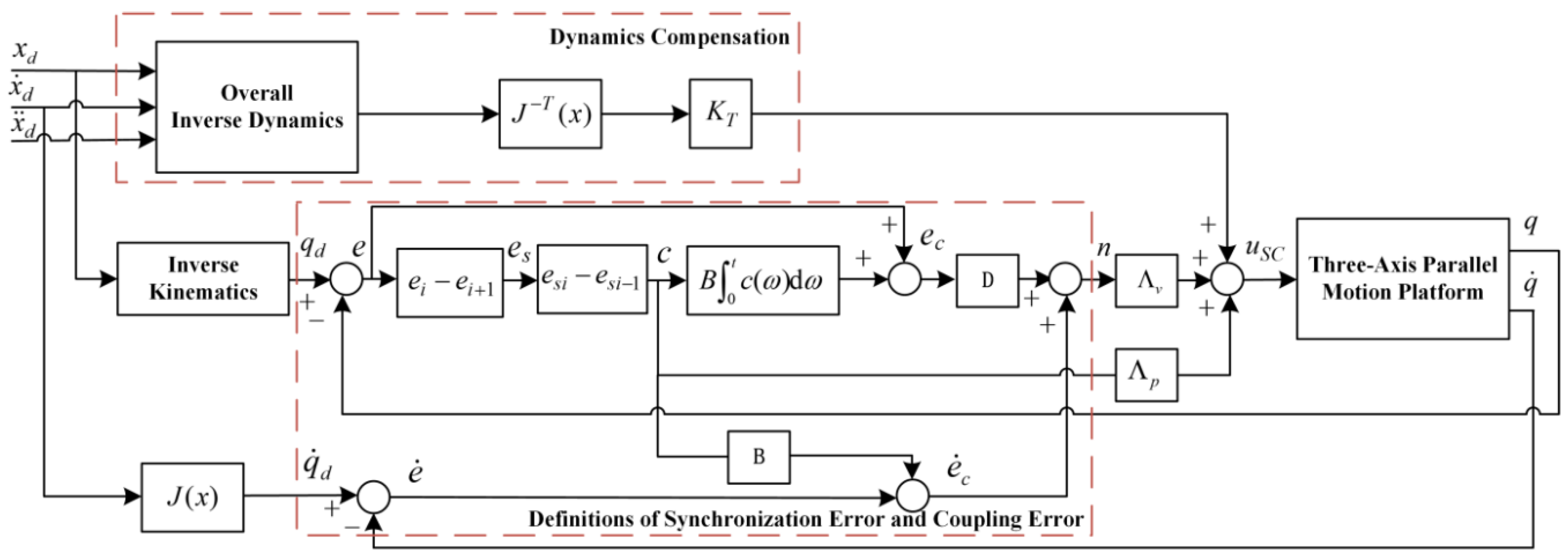
Based on the defined coupling error and synchronization error, along with the analysis of the overall dynamic model, we propose a synchronization controller with dynamics compensation (SC–DC) in the joint space. The control law of the proposed SC–DC can be formulated as follows:
u s c = K T u d + Λ v n ( t ) + Λ p c ( t )
in which
u d = J T ( x ) M ( x ) x ¨ d + C ( x , x ˙ ) x ˙ d + g ( x )
where  u d  is the compensatory command for the motor driving force based on the desired trajectory and dynamic model,  K T  is the feedforward gain matrix for dynamic compensation,  Λ v  and  Λ p  are third-order positive diagonal matrices, and  x ¨ d  and  x ˙ d  are the acceleration and velocity vectors of the desired trajectory, respectively.
By analyzing Equations (25) and (26), the control block diagram of the SC–DC method can be illustrated, as depicted in Figure 3. In the implementation of this control process, the tracking error  ( e ( t ) ) , synchronization error  ( e s ( t ) ) , and coupling error  ( e c ( t ) )  constitute the three core elements. These error vectors can be computed using a series of mathematical formulas, including Equations (15)–(22). Simultaneously, the inverse kinematic equations can be solved through Equation (2), while the overall inverse dynamics can be calculated using Equation (11). Furthermore, the value of  J ( x )  is obtained by solving Equation (4). Several measures are implemented to ensure the stable operation and synchronized execution of the TAPMP. Firstly, the inverse dynamics are introduced for feedforward compensation. Secondly, the coupling error and synchronization error are eliminated. Finally, control commands  ( u s c )  are output to the TAPMP using Equation (25). These steps and formulas collectively constitute the overall control process of the SC–DC method, ensuring the precise motion control of the platform.

4.3. Stability Analysis

After conducting a theoretical analysis of the proposed SC–DC method, the control law specified by Equation (25) is implemented in the TAPMP, and the stability of the closed-loop system is assessed through the application of the Lyapunov stability theorem.
Theorem 1.
The proposed SC–DC method can achieve uniform convergence of the tracking error and synchronization error of the TAPMP towards zero. Specifically, it is established that  e i ( t ) 0 , and  e s i ( t ) 0 , as  t , for i = 1, 2, 3.
Proof. 
By integrating Equations (14) and (25) with the setting of  K T u 1 = u s c , the dynamic model of the closed-loop system can be reformulated as follows:
K T ( u d u 1 ) + Λ v n ( t ) + Λ p c ( t ) = 0
According to Lyapunov theory, the selection of  V  is as follows:
V = 1 2 e s T ( t ) Λ p e s ( t ) + 1 2 0 t c T ( ω ) d ω B Λ p D 0 t c ( ω ) d ω
Differentiating Equation (28), we obtain the following:
V ˙ = e s T ( t ) Λ p e ˙ s ( t ) + c T ( t ) B Λ p D 0 t c ( ω ) d ω
Multiplying Equation (27) by −nT(t) and subsequently inserting the result into Equation (29) leads to the following:
V ˙ = e s T ( t ) Λ p e ˙ s ( t ) + c T ( t ) B Λ p D 0 t c ( ω ) d ω n T ( t ) K T ( u d u 1 ) n T ( t ) Λ v n ( t ) n T ( t ) Λ p c ( t )
Based on Equations (22) and (24), the expression  n T ( t ) Λ p c ( t )  can be reformulated as follows:
n T ( t ) Λ p c ( t ) = e ˙ s T ( t ) Λ p e s ( t ) + c T B Λ p c ( t ) + e s T ( t ) D Λ p e s ( t ) + c T ( t ) B Λ p D 0 t c ( ω ) d ω
Substituting the expression from Equation (31) into Equation (30) results in the following:
V ˙ = n T ( t ) K T ( u d u 1 ) n T ( t ) Λ v n ( t ) c T ( t ) B Λ p c ( t ) e s T ( t ) D Λ p e s ( t )
According to the fundamental theory of the mean value theorem, if  k t u ( q ) q , then  u ( x ) u ( y ) k t x y . Consequently, the elements in Equation (32) can be expressed as follows:
n T ( t ) K T ( u d u 1 ) λ min ( K T ) k t n ( t ) e ( t ) n T ( t ) Λ v n ( t ) λ min ( Λ v ) n ( t ) 2 c T ( t ) B Λ p c ( t ) λ min ( B Λ p ) c ( t ) 2 e s T ( t ) D Λ p e s ( t ) λ min ( D Λ p ) e s ( t ) 2
where  λ min ( K T ) λ min ( Λ v ) λ min ( B Λ p ) , and  λ min ( D Λ p )  are all positive eigenvalues.
Substituting Equation (33) into Equation (32), we obtain the following:
V ˙ λ min ( K T ) k t n ( t ) e ( t ) λ min ( Λ v ) n ( t ) 2 λ min ( B Λ p ) c ( t ) 2 λ min ( D Λ p ) e s ( t ) 2
Considering the value of  λ min ( K T ) k t n ( t ) e ( t )  as non-positive, according to Equation (34), it is implied that  V ˙ 0 , and the vectors  e s ( t ) n ( t ) , and  c ( t )  all converge to 0 as  t .
From Equation (24), it is established that if the vector  n ( t )  is bounded, the coupling error vector also remains bounded. Consequently, the convergence of  e c ( t )  to 0 is affirmed as  t . Referring to Equation (18) and considering  c ( t ) 0 , it can be deduced that, as  t , the following relationship holds:
i = 1 3 e c i ( t ) = i = 1 3 e i ( t ) 0
According to the representational form of the synchronization error, and considering  e s ( t ) 0 , the following obtains:
e 1 ( t ) = e 2 ( t ) = e 3 ( t )
Substituting Equation (36) into Equation (35), we obtain:
e 1 ( t ) = e 2 ( t ) = e 3 ( t ) 0
From Equation (37), it is evident that  e ( t )  converges to 0 as  t .
In summary, the tracking error  e ( t )  and synchronization error  e s ( t )  both converge to 0 as  t , indicating the stability of the proposed controller. □

5. Simulation Analysis of the SC–DC

5.1. Simulation Setup

To investigate the control effect of the proposed controller on trajectory tracking, we conducted a comparative analysis using the APD–DC method, which is based on augmented proportional-derivative (APD) control and dynamics compensation (DC). The control law for the APD–DC method can be represented as follows:
u a p d = K T 1 u d + k v e ˙ ( t ) + k p e ( t )
in which
u d = J T M D ( x ) x ¨ d + C D ( x , x ˙ ) x ˙ d + g D ( x )
where  k v  and  k p  are third-order positive diagonal coefficient matrices,  K T 1  is the feedforward gain matrix for dynamic compensation, and  u d    is the motor drive force compensation command similar to that of the proposed controller.
After analyzing the control laws of both the SC–DC and APD–DC methods, it was determined that both are grounded in the dynamic model. Subsequently, the dynamic parameters were identified using the least squares methods, yielding the following parameter values:  m p = 1.835   kg m 1 = 4.776   kg m 2 = 1.946   kg m 3 = 4.775   kg I y = 77.68   kg cm 2 L 1 = 90   mm , and  g = 9.8   m / s 2 .
To ensure a fair comparison between the algorithms, optimal control parameters were customized for both methods. The parameters specific to the proposed controller are outlined as follows:
Λ p = d i a g [ 8000 , 8000 , 8850 ] ,   Λ v = d i a g [ 150 , 158.5 , 108.5 ] ,   B = d i a g [ 0.0005 , 8.1 , 1.5 ] , D = d i a g [ 200 , 200 , 200 ] ,   K T = d i a g [ 0.000041 , 0.000041 , 0.000041 ]
Analogously, the parameters for the APD–DC method are enumerated as follows:
k p = Λ p ,   k e = Λ v ,   K T 1 = K T .

5.2. Simulation Results

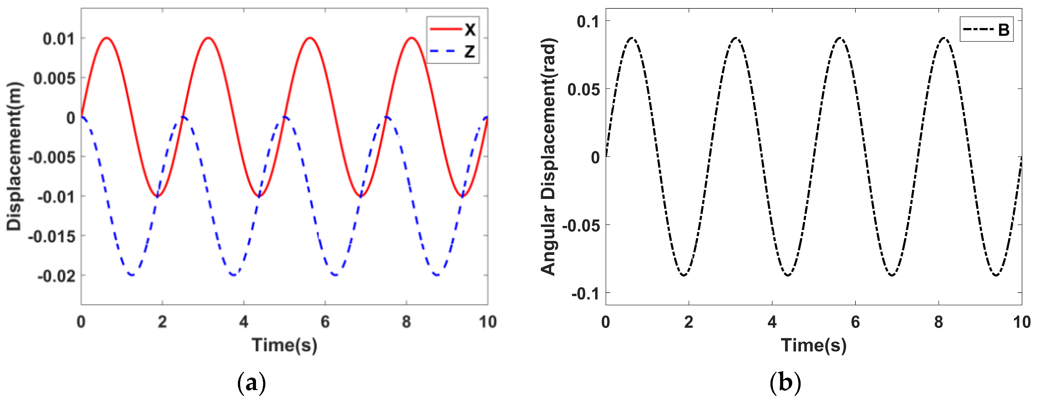
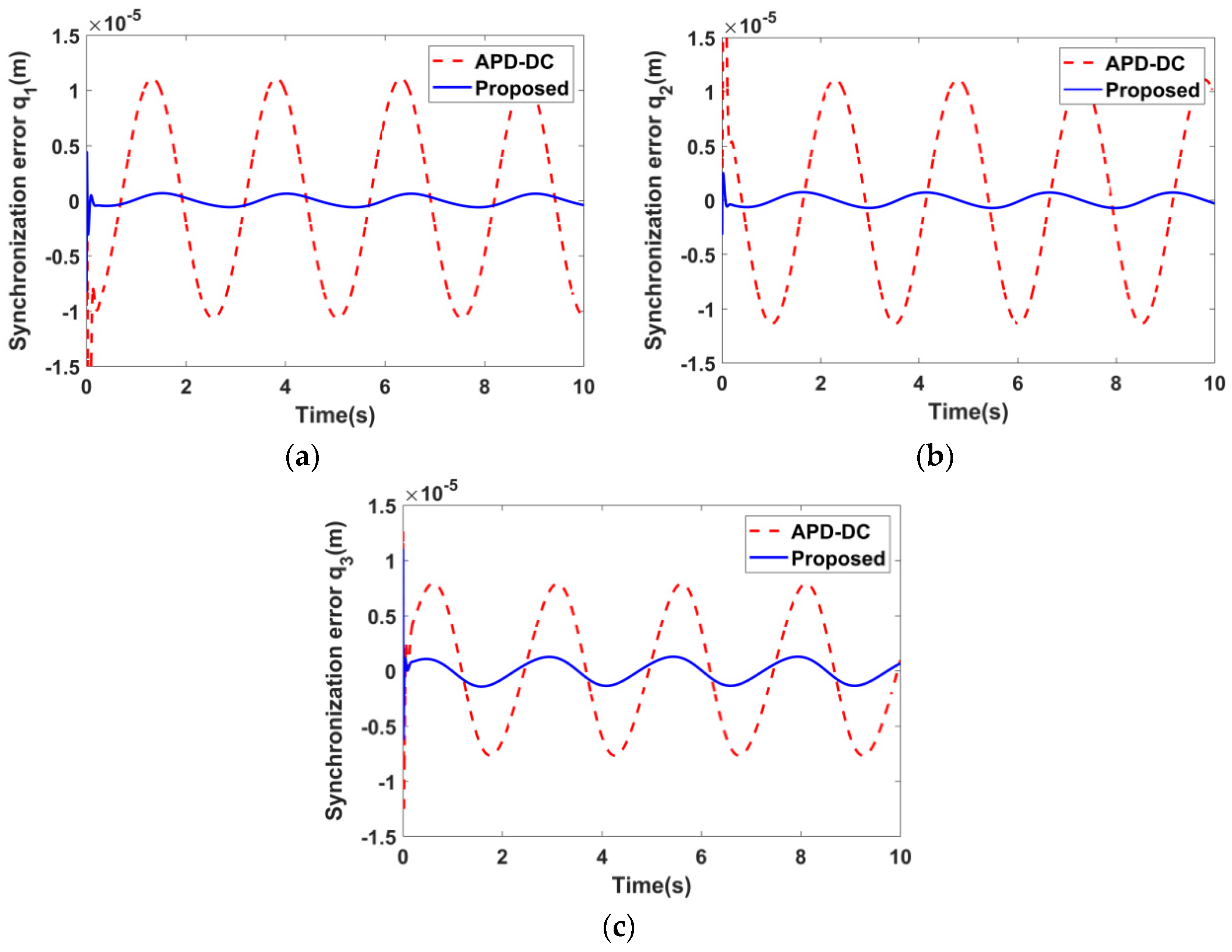
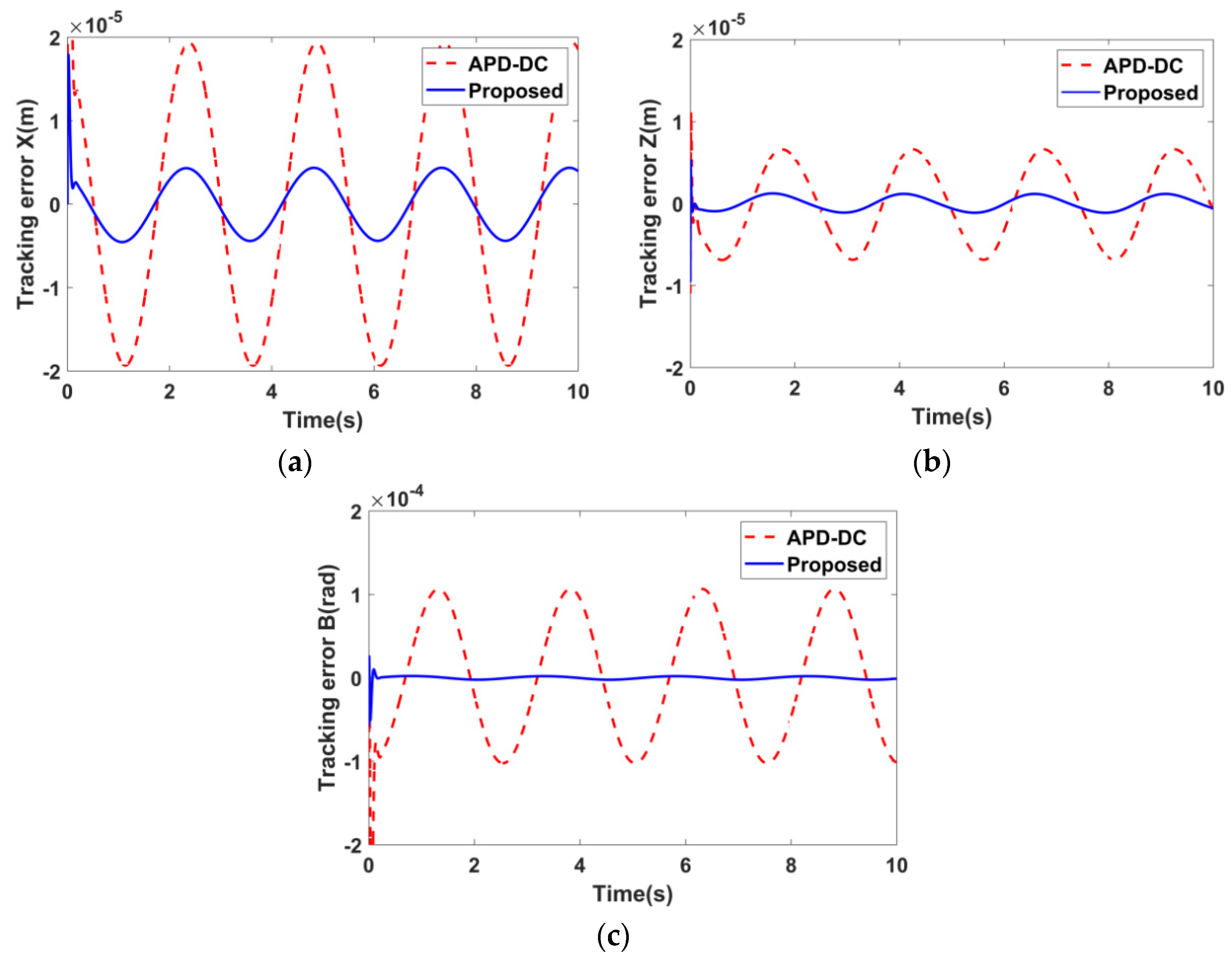
The circular trajectories, centered at [0, −0.01]T, with a radius of 0.01 m and a frequency of 0.4 Hz, as well as sinusoidal trajectories with an amplitude of 5° and a frequency of 0.4 Hz, served as reference inputs for the XZ plane and the B-axis, respectively, as shown in Figure 4. The tracking error and synchronization error of each motor, along with the tracking error of each drive axis, are depicted in Figure 5, Figure 6 and Figure 7, respectively.
From these figures, it is evident that the proposed controller can significantly reduce both the tracking error and synchronization error of the motor compared to the APD–DC method, thereby enhancing the tracking accuracy of each drive axis. Additionally, the proposed controller exhibits smaller trajectory errors throughout the entire motion process, exhibiting better control effects in terms of velocity, stability, and control precision. Hence, the proposed controller provides us with an effective control approach to improve the tracking performance for multi-axis parallel machine tools.
To quantitatively evaluate the performance of the proposed controller, a comprehensive assessment is conducted using standard deviation (STD) and mean absolute error (MAE). Table 1, Table 2 and Table 3 present the tracking error and synchronization error of each motor, as well as the tracking error of each drive axis, respectively.
The simulation results indicate that the proposed controller demonstrates superior tracking accuracy and synchronization performance compared to the APD–DC method. Specifically, upon the application of the proposed controller, the MAE for the tracking error and synchronization error of motor q1 is reduced from 6.87 μm and 6.98 μm to 2.74 μm and 0.4 μm, respectively, representing reductions of 60.12% and 94.27% compared to the APD–DC method. Additionally, the MAE tracking error for the X- and Z-axes also decreases from 12.53 μm and 4.26 μm to 2.85 μm and 0.72 μm, respectively, constituting reductions of 77.25% and 83.1% compared to the APD–DC method.

6. Experimental Verification of the SC–DC

6.1. Experimental Setup

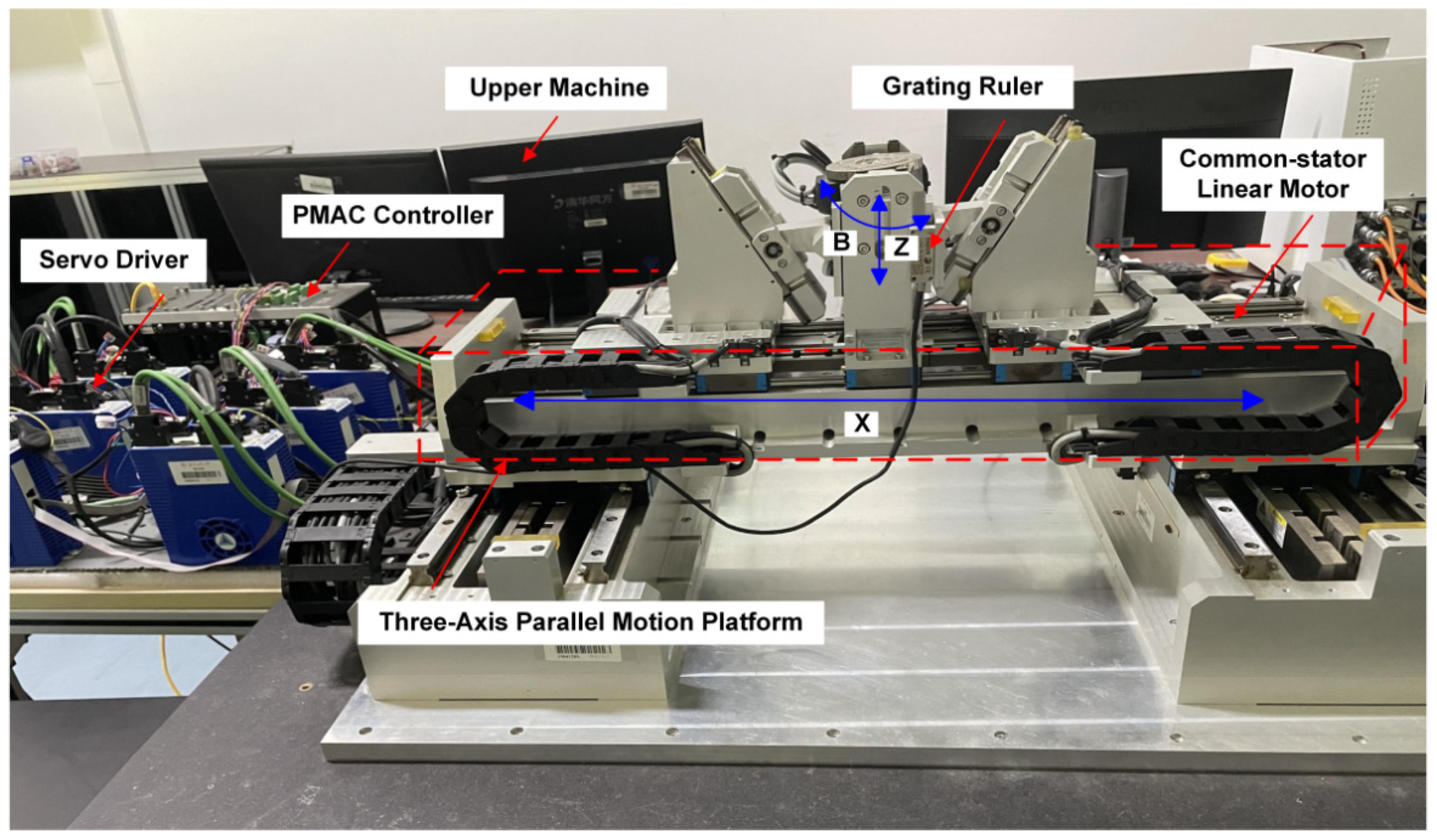
To validate the proposed controller and ensure its stable operation in practical applications, we established an experimental system based on the Programmable Multi-Axes Controller (PMAC), as depicted in Figure 8. The system comprises a PMAC controller, servo driver, upper machine, precision grating ruler, and three linear motors with a common stator. For the experimentation, we utilized a linear motor of the AUM5-S3 type, a servo driver of the ASD240 model, and a precision grating ruler of the RGH22S30D61 variety. The grating ruler possesses a resolution of 100 nm, with a sampling period of 0.0001 s. Furthermore, Figure 9 presents the hardware relationship diagram. The PMAC controller accurately regulates the servo driver by outputting analog voltage commands, ultimately achieving precise control of the motor. This design improves the overall efficiency and stability of the system, thereby ensuring high precision and reliable operation.

6.2. Experimental Results

In the experimental process, the circular trajectories with a center at [0, −0.01]T and a radius of 0.01 m, as well as sinusoidal trajectories with an amplitude of 5° and a frequency of 0.18 Hz, were designated as the desired motion trajectories for the XZ plane and the B-axis, respectively. We utilized both the proposed controller and the APD–DC to achieve precise control of the motion trajectories.
To optimize the controller parameters, the following parameter tuning steps were implemented. Considering that the APD–DC method served as the basis for designing the proposed SC–DC method, optimal parameters were selected for the APD–DC method to determine its optimal control gains. Subsequently, since the proposed SC–DC method introduces additional auxiliary terms based on the APD–DC method, a trial-and-error method was employed to optimize these auxiliary term parameters. Furthermore, dynamic identification methods were used to determine the dynamic parameters of mass and moment of inertia for both algorithms, similar to the simulation analysis. Consequently, optimal parameters were determined for both algorithms. Thus, the parameters of the proposed SC–DC method are expressed as follows:
Λ p = d i a g [ 3.8 , 3 , 4 ] ,   Λ v = d i a g [ 30 , 30 , 28 ] ,   B = d i a g [ 0.00059 , 0.00051 , 0.00059 ] , D = d i a g [ 50 , 50 , 50 ] ,   K T = d i a g [ 0.00003 , 0.00003 , 0.00003 ]
The control parameters for the APD–DC method are represented as follows:
k p = d i a g [ 3.8 , 3 , 4 ] ,   k e = d i a g [ 30 , 30 , 28 ] ,   K T 1 = d i a g [ 0.00003 , 0.00003 , 0.00003 ] .
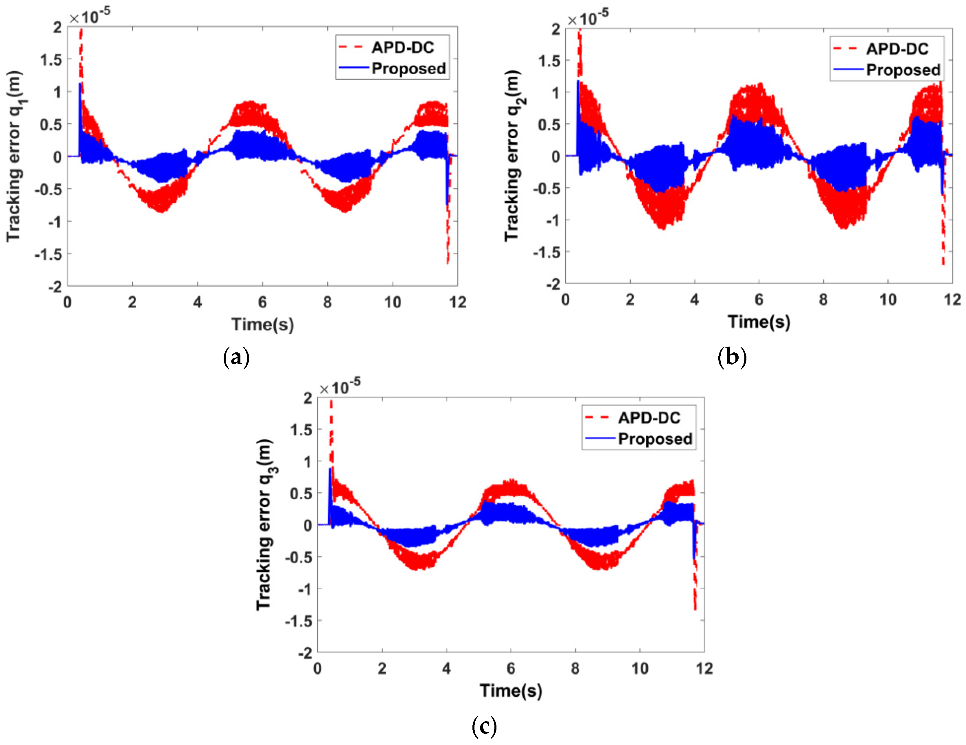
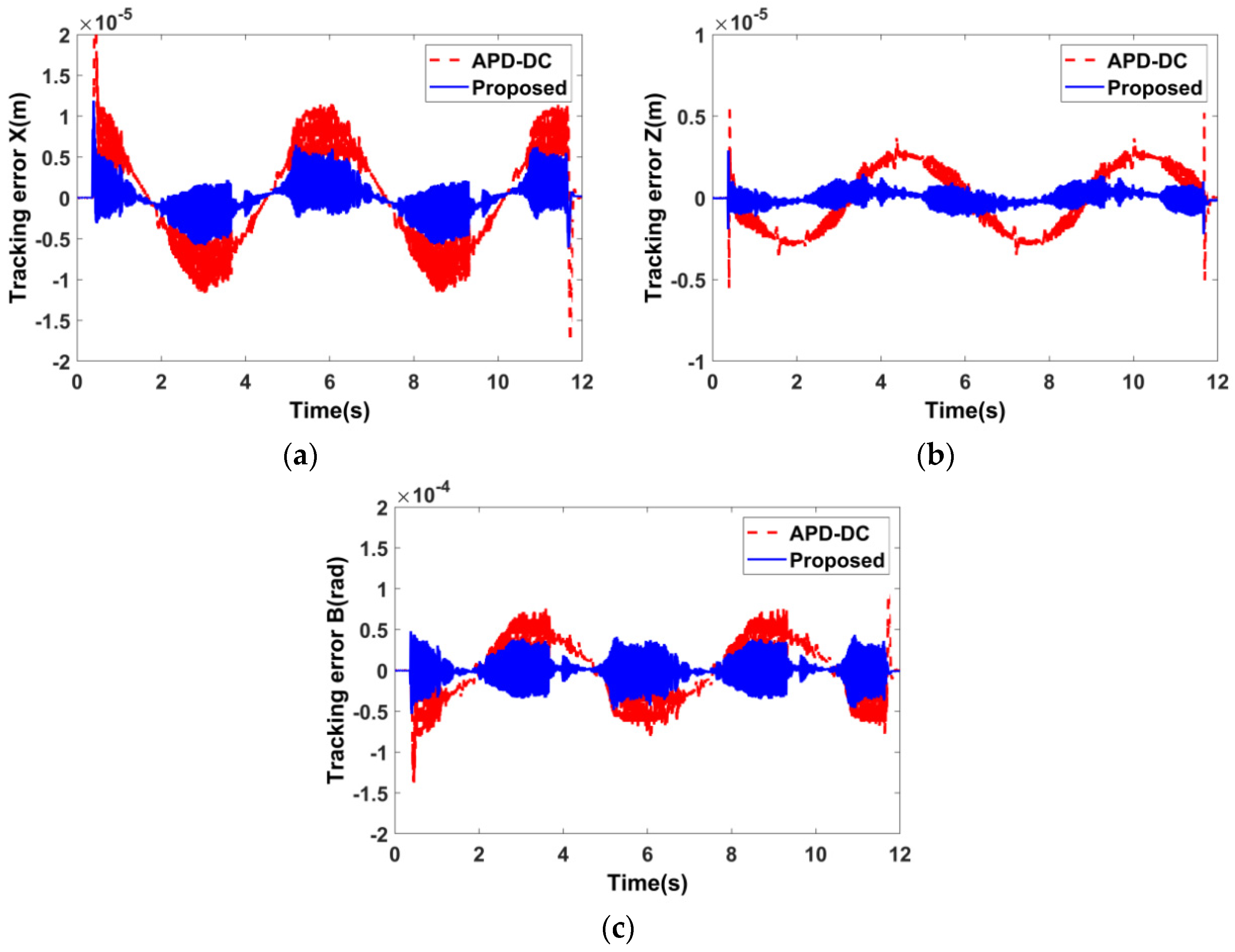
The experimental results obtained by applying the proposed controller and APD–DC method are illustrated in Figure 10, Figure 11 and Figure 12. Figure 10 and Figure 11 depict the tracking error and synchronization error of each motor, respectively. It can be observed from these figures that both control methods offer satisfactory tracking and synchronization performance, with the maximum tracking error and maximum synchronization error for all motors being less than 0.2 mm and 0.1 mm, respectively. Furthermore, our controller demonstrates superior effectiveness in oscillation suppression, tracking accuracy, and motion synchronization. Figure 12 shows the tracking error of each driving axis, indicating that the proposed controller exhibits a smaller maximum tracking error throughout the motion process and can rapidly reduce the motion error during constant velocity motion.
To comprehensively evaluate the motion performance of the proposed controller, Table 4, Table 5 and Table 6 present experimental results of the performance indicators for the tracking error and synchronization error of the common stator motor, as well as the tracking error of each drive axis.
Based on these performance indicators, it is evident that the proposed controller significantly outperforms the APD–DC method in terms of tracking and synchronization performance. Specifically, the proposed controller demonstrates higher accuracy for the trajectory tracking process, confirming its exceptional performance in precise tracking and maintaining stable synchronization. Moreover, it exhibits improved coordination of motion between motors, thereby enhancing the motion accuracy of the TAPMP in both joint and task spaces. Notably, after applying the proposed controller, the MAE of the tracking error and synchronization error on motor q1 is reduced from 4.16 μm and 1.89 μm to 1.17 μm and 0.51 μm, respectively, representing only 71.88% and 73.02% of the APD–DC method. Simultaneously, the MAE tracking error for the X- and Z-axes decreases from 5 μm and 1.63 μm to 1.43 μm and 0.32 μm, respectively, accounting for only 71.4% and 80.37% of the APD–DC method. Furthermore, by comparing the simulation and experimental results in Table 1, Table 2, Table 3, Table 4, Table 5 and Table 6, it can be observed that there are certain discrepancies in the extent of error reduction between them. These disparities primarily arise from the inconsistency between the error dynamics of the simulation model and those of the actual system, as well as the limitations imposed by the servo cycle. Nevertheless, the trend of error reduction remains consistent in both scenarios. This mutual validation further corroborates the feasibility and effectiveness of the proposed strategy.

7. Conclusions

In this paper, a synchronization controller in joint space was proposed to enhance the motion coordination of the common stator motor in the TAPMP. The synchronization error of the common stator motor was employed to represent the synchronization relationship between the adjacent motors. The stability of the proposed controller was analyzed using Lyapunov theory. Through simulation analysis and experimental studies, the trajectory tracking effectiveness and synchronization stability performance of the proposed controller were validated. The experimental results demonstrate that, compared to the APD–DC method, the proposed controller significantly reduces both the MAE of the tracking error and synchronization error on the q1 motor by 71.88% and 73.02%, respectively. Additionally, the proposed controller decreases the MAE of the end-effector’s tracking error on the X- and Z-axes by 71.4% and 80.37%, respectively. This paper thus offers a novel strategy for the trajectory tracking and synchronization control of multi-axis parallel platforms. In future research, we aim to further refine the proposed synchronization control strategy by incorporating model-free decoupling control based on time-delay estimation for the application to a five-axis hybrid motion platform.

Author Contributions

Writing—original draft and methodology, Z.Z.; funding acquisition, supervision, and project administration, J.G.; investigation, L.Z. All authors have read and agreed to the published version of the manuscript.

Funding

This research received support from the National Natural Science Foundation of China (Grant No. 52075106 and No. 52375488), the Ministry of Industry and Information Technology of China (Grant No. TC220A04A-206), R&D project of Guangdong Province (Grant No. 20220166003240), and the Natural Science Foundation of Guangdong Province (Grant No. 2024A1515030003).

Data Availability Statement

Data are contained within the article.

Conflicts of Interest

The authors declare no conflicts of interest.

References

  1. Rosyid, A.; Stefanini, C.; El-Khasawneh, B. A Reconfigurable Parallel Robot for On-Structure Machining of Large Structures. Robotics 2022, 11, 110. [Google Scholar] [CrossRef]
  2. Wang, K.; Li, J.; Shen, H.P.; You, J.J.; Yang, T.L. Inverse Dynamics of A 3-DOF Parallel Mechanism Based on Analytical Forward Kinematics. Chin. J. Mech. Eng. 2022, 35, 212–221. [Google Scholar] [CrossRef]
  3. Shen, H.P.; Zhao, Y.N.; Li, J.; Wu, G.L.; Chablat, D. A novel partially-decoupled translational parallel manipulator with symbolic kinematics, singularity identification and workspace determination. Mech. Mach. Theory 2021, 164, 104388. [Google Scholar] [CrossRef]
  4. Luo, Y.H.; Gao, J.; Zhang, L.Y.; Chen, D.S.; Chen, X. Kinematic calibration of a symmetric parallel kinematic machine using sensitivity-based iterative planning. Precis. Eng. 2022, 77, 164–178. [Google Scholar] [CrossRef]
  5. Ye, H.; Wang, D.; Wu, J.; Yue, Y.; Zhou, Y.L. Forward and inverse kinematics of a 5-DOF hybrid robot for composite material machining. Robot. Comput. Integr. Manuf. 2020, 65, 101961. [Google Scholar] [CrossRef]
  6. Wu, J.; Wang, J.S.; You, Z. A comparison study on the dynamics of planar 3-DOF 4-RRR, 3-RRR and 2-RRR parallel manipulators. Robot. Comput. Integr. Manuf. 2011, 27, 150–156. [Google Scholar] [CrossRef]
  7. Wang, G.L.; Wang, Y.; Lv, B.R.; Ma, R.P.; Liu, L. Research on a New Type of Rigid-Flexible Coupling 3-DOF Micro-Positioning Platform. Micromachines 2020, 11, 1015. [Google Scholar] [CrossRef] [PubMed]
  8. Bettega, J.; Richiedei, D.; Trevisani, A. Using Pose-Dependent Model Predictive Control for Path Tracking with Bounded Tensions in a 3-DOF Spatial Cable Suspended Parallel Robot. Machines 2022, 10, 453. [Google Scholar] [CrossRef]
  9. Wang, H.; Ren, W.; Cheah, C.C.; Xie, Y.; Lyu, S. Dynamic Modularity Approach to Adaptive Control of Robotic Systems with Closed Architecture. IEEE Trans. Autom. Control 2020, 65, 2760–2767. [Google Scholar] [CrossRef]
  10. Harandi, M.R.J.; Khalilpour, S.A.; Taghirad, H.D.; Romero, J.G. Adaptive control of parallel robots with uncertain kinematics and dynamics. Mech. Syst. Signal Process. 2021, 157, 107693. [Google Scholar] [CrossRef]
  11. Azarfar, A.; Azarfar, B.; Vahedi, M. Self-Tuning Fuzzy Task Space Controller for Puma 560 Robot. J. Electr. Eng. Technol. 2020, 16, 579–589. [Google Scholar] [CrossRef]
  12. Khalilpour, S.A.; Khorrambakht, R.; Taghirad, H.D.; Cardou, P. Robust cascade control of a deployable cable-driven robot. Mech. Syst. Signal Process. 2019, 127, 513–530. [Google Scholar] [CrossRef]
  13. Zi, B.; Duan, B.Y.; Du, J.L.; Bao, H. Dynamic modeling and active control of a cable-suspended parallel robot. Mechatronics 2008, 18, 1–12. [Google Scholar] [CrossRef]
  14. Zhu, Y.K.; Qiao, J.Z.; Guo, L. Adaptive Sliding Mode Disturbance Observer-Based Composite Control With Prescribed Performance of Space Manipulators for Target Capturing. IEEE Trans. Ind. Electron. 2019, 66, 1973–1983. [Google Scholar] [CrossRef]
  15. Fonseca, M.D.P.A.; Adorno, B.V.; Fraisse, P. Coupled Task-Space Admittance Controller Using Dual Quaternion Logarithmic Mapping. IEEE Robot. Autom. Lett. 2020, 5, 6057–6064. [Google Scholar] [CrossRef]
  16. Altan, A.; Hacioglu, R. Model predictive control of three-axis gimbal system mounted on UAV for real-time target tracking under external disturbances. Mech. Syst. Signal Process. 2020, 138, 106548. [Google Scholar] [CrossRef]
  17. Zhou, S.L.; Sun, J.; Gao, F. Influence of flexible spherical joints parameters on accuracy of the six-axis force/torque sensor with three-three orthogonal parallel mechanism. Mech. Mach. Theory 2020, 145, 103697. [Google Scholar] [CrossRef]
  18. Nguyen, V.L.; Caverly, R.J. Cable-Driven Parallel Robot Pose Estimation Using Extended Kalman Filtering with Inertial Payload Measurements. IEEE Robot. Autom. Lett. 2021, 6, 3615–3622. [Google Scholar] [CrossRef]
  19. Bayani, H.; Masouleh, M.T.; Kalhor, A. An experimental study on the vision-based control and identification of planar cable-driven parallel robots. Robot. Auton. Syst. 2016, 75, 187–202. [Google Scholar] [CrossRef]
  20. Li, P.C.; Shu, T.T.; Xie, W.F.; Tian, W. Dynamic Visual Servoing of A 6-RSS Parallel Robot Based on Optical CMM. J. Intell. Robot. Syst. 2021, 102, 40. [Google Scholar] [CrossRef]
  21. Merlet, J.P. Simulation of Discrete-Time Controlled Cable-Driven Parallel Robots on a Trajectory. IEEE Trans. Robot. 2017, 33, 675–688. [Google Scholar] [CrossRef]
  22. Dong, C.L.; Liu, H.T.; Xiao, J.L.; Huang, T. Dynamic modeling and design of a 5-DOF hybrid robot for machining. Mech. Mach. Theory 2021, 165, 104438. [Google Scholar] [CrossRef]
  23. Bodie, K.; Tognon, M.; Siegwart, R. Dynamic End Effector Tracking with an Omnidirectional Parallel Aerial Manipulator. IEEE Robot. Autom. Lett. 2021, 6, 8165–8172. [Google Scholar] [CrossRef]
  24. Ji, H.; Shang, W.W.; Cong, S. Adaptive Synchronization Control of Cable-Driven Parallel Robots with Uncertain Kinematics and Dynamics. IEEE Trans. Ind. Electron. 2021, 68, 8444–8454. [Google Scholar] [CrossRef]
  25. Fang, S.; Franitza, D.; Torlo, M.; Bekes, F.; Hiller, M. Motion control of a tendon-based parallel manipulator using optimal tension distribution. IEEE/ASME Trans. Mechatron. 2004, 9, 561–568. [Google Scholar] [CrossRef]
  26. Hosseini, M.I.; Khalilpour, S.A.; Taghirad, H.D. Practical robust nonlinear PD controller for cable-driven parallel manipulators. Nonlinear Dyn. 2021, 106, 405–424. [Google Scholar] [CrossRef]
  27. Feng, C.L.; Chen, W.D.; Shao, M.Q.; Ni, S.H. Trajectory Tracking and Adaptive Fuzzy Vibration Control of Multilink Space Manipulators with Experimental Validation. Actuators 2023, 12, 138. [Google Scholar] [CrossRef]
  28. Yang, H.; Wu, S.; Huang, G. Fuzzy neural network control for mechanical arm based on adaptive friction compensation. J. Vibroeng. 2020, 22, 1099–1112. [Google Scholar] [CrossRef]
  29. Escorcia-Hernandez, J.M.; Aguilar-Sierra, H.; Aguilar-Mejia, O.; Chemori, A.; Arroyo-Nunez, J.H. A New Adaptive RISE Feedforward Approach based on Associative Memory Neural Networks for the Control of PKMs. J. Intell. Robot. Syst. 2020, 100, 827–847. [Google Scholar] [CrossRef]
  30. Zhang, B.B.; Wu, J.; Wang, L.P.; Yu, Z.Y. Accurate dynamic modeling and control parameters design of an industrial hybrid spray-painting robot. Robot. Comput. Integr. Manuf. 2020, 63, 101923. [Google Scholar] [CrossRef]
  31. Yen, P.L.; Lai, C.C. Dynamic modeling and control of a 3-DOF Cartesian parallel manipulator. Mechatronics 2009, 19, 390–398. [Google Scholar] [CrossRef]
  32. Xie, Z.H.; Xie, F.G.; Liu, X.J.; Wang, J.S.; Mei, B. Tracking error prediction informed motion control of a parallel machine tool for high-performance machining. Int. J. Mach. Tools Manuf. 2021, 164, 103714. [Google Scholar] [CrossRef]
  33. Makarem, S.; Delibas, B.; Koc, B. Data-Driven Tuning of PID Controlled Piezoelectric Ultrasonic Motor. Actuators 2021, 10, 148. [Google Scholar] [CrossRef]
  34. Baek, J.; Cho, S.; Han, S. Practical Time-Delay Control with Adaptive Gains for Trajectory Tracking of Robot Manipulators. IEEE Trans. Ind. Electron. 2018, 65, 5682–5692. [Google Scholar] [CrossRef]
  35. Sun, Y.G.; Qiang, H.Y.; Wang, L.; Ji, W.; Mardani, A. A Fuzzy-Logic-System-Based Cooperative Control for the Multielectromagnets Suspension System of Maglev Trains with Experimental Verification. IEEE Trans. Fuzzy Syst. 2023, 31, 3411–3422. [Google Scholar] [CrossRef]
  36. Li, J.B.; Wang, C.J. Dynamics Modeling and Adaptive Sliding Mode Control of a Hybrid Condenser Cleaning Robot. Actuators 2022, 11, 119. [Google Scholar] [CrossRef]
  37. Ning, B.D.; Han, Q.L.; Sanjayan, J.; Shang, W.W.; Lam, W.Y. Robust trajectory tracking control for cable-driven parallel with model uncertainty. Control. Eng. Pract. 2023, 140, 105662. [Google Scholar] [CrossRef]
  38. Zhong, Y.B.; Gao, J.; Zhang, L.Y. Fractional-order feedforward control method for permanent magnet linear synchronous motor based on frequency-domain adjustment theory. Mech. Syst. Signal Process. 2023, 190, 110115. [Google Scholar] [CrossRef]
  39. Luo, Y.H.; Gao, J.; Chen, D.S.; Zhang, L.Y.; Liu, Y.C.; Zhong, Y.B. Accurate error compensation method for multi-axis parallel machine via singularized jacobi geometric parameter correction and coupling error evaluation. Robot. Comput. Integr. Manuf. 2024, 89, 102771. [Google Scholar] [CrossRef]
  40. Martinez, O.; Soto, I.; Campa, R. Mathematical modeling of a 3-CUP parallel mechanism using the Fermat point. Mech. Mach. Theory 2021, 161, 104326. [Google Scholar] [CrossRef]
  41. Guo, F.; Cheng, G.; Pang, Y.S. Explicit dynamic modeling with joint friction and coupling analysis of a 5-DOF hybrid polishing robot. Mech. Mach. Theory 2022, 167, 104509. [Google Scholar] [CrossRef]
Figure 1. Overall structure of the designed TAPMP.
Actuators 13 00166 g001
Figure 2. Kinematic model of the TAPMP.
Actuators 13 00166 g002
Figure 3. Block diagram illustrating the control structure of the proposed SC–DC scheme.
Actuators 13 00166 g003
Figure 4. Desired trajectory of the TAPMP in the task space. (a) X- and Z-axis, (b) B-axis.
Actuators 13 00166 g004
Figure 5. Tracking error of each motor with APD–DC and the proposed controller. (a) Motor q1, (b) motor q2, (c) motor q3.
Actuators 13 00166 g005
Figure 6. Synchronization error of each motor with APD–DC and the proposed controller. (a) Motor q1, (b) motor q2, (c) motor q3.
Actuators 13 00166 g006
Figure 7. Tracking error of each drive axis with APD–DC and the proposed controller. (a) X-axis, (b) Z-axis, (c) B-axis.
Actuators 13 00166 g007
Figure 8. Experimental system of the TAPMP.
Actuators 13 00166 g008
Figure 9. Hardware relationship diagram of the TAPMP.
Actuators 13 00166 g009
Figure 10. Experimental results of the tracking error for each motor with APD–DC and the proposed controller. (a) Motor q1, (b) motor q2, (c) motor q3.
Actuators 13 00166 g010
Figure 11. Experimental results of the synchronization error for each motor with APD–DC and the proposed controller. (a) Motor q1, (b) motor q2, (c) motor q3.
Actuators 13 00166 g011
Figure 12. Experimental results of the tracking error for each drive axis with APD–DC and the proposed controller. (a) X-axis, (b) Z-axis, (c) B-axis.
Actuators 13 00166 g012
Table 1. Comparison of the tracking error for each motor with APD–DC and the proposed controller.
Control StrategyTracking Error (μm)
STDMAE
q1q2q3q1q2q3
APD–DC7.8314.216.696.8712.535.87
Proposed3.163.283.292.742.852.89
Reduction (%) (proposed compared with APD–DC)59.6476.9250.8260.1277.2550.77
Table 2. Comparison of the synchronization error for each motor with APD–DC and the proposed controller.
Control StrategySynchronization Error (μm)
STDMAE
q1q2q3q1q2q3
APD–DC7.898.205.496.987.264.92
Proposed0.480.520.950.400.460.83
Reduction (%) (proposed compared with APD–DC)93.9293.6682.794.2793.6683.13
Table 3. Comparison of the tracking error for each drive axis with APD–DC and the proposed controller.
Control StrategyTracking Error
STDMAE
X (μm)Z (μm)B (μrad)X (μm)Z (μm)B (μrad)
APD–DC14.214.7575.9512.534.2667.16
Proposed3.280.823.182.850.721.62
Reduction (%) (proposed compared with APD–DC)76.9282.7495.8177.2583.197.59
Table 4. Experimental comparison of the tracking error for each motor with APD–DC and the proposed controller.
Control StrategyTracking Error (μm)
STDMAE
q1q2q3q1q2q3
APD–DC4.935.984.274.165.003.62
Proposed1.592.021.541.171.431.21
Reduction (%) (proposed compared with APD–DC)67.7566.2263.9371.8871.466.57
Table 5. Experimental comparison of the synchronization error for each motor with APD–DC and the proposed controller.
Control StrategySynchronization Error (μm)
STDMAE
q1q2q3q1q2q3
APD–DC2.171.862.161.891.471.89
Proposed 0.650.880.460.510.620.37
Reduction (%) (proposed compared with APD–DC)70.0152.6978.773.0257.8280.42
Table 6. Experimental comparison of the tracking error for each axis with APD–DC and the proposed controller.
Control StrategyTracking Error
STDMAE
X (μm)Z (μm)B (μrad)X (μm)Z (μm)B (μrad)
APD–DC5.981.8733.015.001.6326.55
Proposed2.020.3914.211.430.3210.17
Reduction (%) (proposed compared with APD–DC)66.2279.1456.9571.480.3761.69
Disclaimer/Publisher’s Note: The statements, opinions and data contained in all publications are solely those of the individual author(s) and contributor(s) and not of MDPI and/or the editor(s). MDPI and/or the editor(s) disclaim responsibility for any injury to people or property resulting from any ideas, methods, instructions or products referred to in the content.