Article

A Tube-Based Model Predictive Control for Path Tracking of Autonomous Articulated Vehicle

1
Department of Automotive Engineering, Seoul National University of Science and Technology, Seoul 01811, Republic of Korea
2
Department of Mechanical and Automotive Engineering, Seoul National University of Science and Technology, Seoul 01811, Republic of Korea
*
Author to whom correspondence should be addressed.
Actuators 2024, 13(5), 164; https://doi.org/10.3390/act13050164
Submission received: 12 April 2024 / Revised: 26 April 2024 / Accepted: 27 April 2024 / Published: 1 May 2024
(This article belongs to the Special Issue Integrated Intelligent Vehicle Dynamics and Control)

Abstract

:
This paper presents tube-based Model Predictive Control (MPC) for the path and velocity tracking of an autonomous articulated vehicle. The target platform of this study is an autonomous articulated vehicle with a non-steerable axle. Consequently, the articulation angle and wheel torque input are determined by the tube-based MPC. The proposed MPC aims to achieve two objectives: minimizing path tracking error and enhancing robustness to disturbances. Furthermore, the lateral stability of the autonomous articulated vehicle is considered to reflect its dynamic characteristics. The vehicle model for the MPC is formulated using local linearization to minimize modeling errors. The reference state is determined using a virtual controller based on the linear quadratic regulator to provide the optimal reference for the MPC solver. The proposed algorithm was evaluated through a simulation study with base algorithms under noise injection into the sensor signal. Simulation results demonstrate that the proposed algorithm achieved the smallest path tracking error, compared to the base algorithms. Additionally, the proposed algorithm demonstrated robustness to external noise for multiple signals.

1. Introduction

The scope of autonomous driving has expanded beyond passenger vehicles to include commercial vehicles [1]. Trucks and buses, among other commercial vehicles, share similar steering and driving mechanisms with passenger cars, and achieving satisfactory driving performance typically involves adapting supplementary algorithms to meet specific requirements [2,3]. For example, autonomous buses experience notable variations in vehicle mass depending on passenger load, a factor not as pronounced in autonomous cars. Consequently, real-time estimation of mass and center of gravity becomes crucial, with these factors needing incorporation into the controller [4]. Similarly, self-driving trucks exhibit mass and center of gravity variations based on cargo load, necessitating the use of estimators akin to those used for autonomous buses [5]. Therefore, both passenger cars, which have served as primary platforms for autonomous driving research, and commercial vehicles with comparable steering and driving mechanisms can share the basic structure of the vehicle controller. However, significant differences in the actuation mechanism would require the development of a distinct control algorithm, separate from that of passenger autonomous vehicles.
In addition to the conventional front wheel steering mechanism, ground vehicles utilize various steering mechanisms, including four wheel steering [6], skid steering [7], and articulated frame steering [8]. These steering mechanisms are commonly employed alongside front wheel steering. The four-wheel steering mechanism, being an extension of front wheel steering, allows for a similar controller application to determine both front and rear steering angles for path tracking [9,10]. However, skid and articulated frame steering employ significantly different actuation mechanisms, compared to front wheel steering. Skid steering has traditionally been prevalent in construction heavy equipment like wheel loaders, but, in recent years, it has been gradually replaced by articulated steering-based vehicles, due to several advantages offered by articulated steering. Articulated steering vehicles provide benefits such as a wider viewing angle, improved maneuverability, reduced tire wear, and enhanced fuel efficiency, compared to skid vehicles [11]. Consequently, there is an increasing demand for articulated vehicles beyond current usage. As articulated structures are primarily employed in commercial vehicles, there is a growing need for the autonomous driving of articulated vehicles to enhance operational efficiency and minimize manual labor requirements. Therefore, research on a path tracking controller that accommodates the unique steering structure of articulated vehicles is imperative.
An analysis of the articulated vehicle was conducted prior to designing the path tracking controller. The dynamic characteristics of articulated vehicles can be summarized in three key aspects. Firstly, the front and rear bodies exhibit distinct dynamic behavior. As the front body of the vehicle serves as the steering mechanism, it typically experiences greater lateral acceleration and yaw rate, compared to the rear part [12]. Secondly, the articulation structure is more susceptible to lateral instability. Specifically, snaking instability and jackknife phenomena are more likely to occur in articulated vehicles than in front wheel-steering vehicles [13]. This tendency becomes more pronounced at higher driving speeds or when the articulation angle is large, due to traveling on roads with sharp curvature [14]. Additionally, the center of gravity of articulated vehicles is higher than that of passenger cars, as articulated vehicles are primarily used in commercial applications. This elevated center of gravity contributes to reduced lateral stability. Finally, the hydraulic actuator for articulation exhibits a relatively slower response. compared to the electric power steering used in passenger cars [15].
Path tracking controllers for articulated vehicles are classified based on the presence of steering wheels. When a steering wheel is present on the front body of the articulating vehicle, an actuator controlling the articulation of the vehicle body is generally not used. Therefore, the articulation angle becomes a vehicle state determined by front wheel steering and is not used as a control input for path tracking [16,17,18,19]. In this scenario, a nonlinear kinematic equation is employed to represent the relationship between front wheel steering and the articulation angle. The kinematic equation is linearized to design a circular path tracking controller [16]. However, since this approach relies on exact linearization, the tracking controller is defined only for straight and circular paths, limiting its applicability to other path geometries. Similarly, a linear vehicle model and a potential field approach are utilized to plan the optimal path for an articulated vehicle with two trailers [17]. However, the potential field implementation as a sigmoid function may struggle to respond effectively in the presence of complex obstacles. Additionally, since the articulation angle is passively determined by front steering in both approaches, snake oscillation or jackknife phenomena can occur if the steering control input is not properly limited based on the vehicle’s state. To address the stability problem of articulated vehicles with steerable wheels, phase plane analysis is introduced to maintain lateral stability [18]. However, phase planes depend on the path radius and the vehicle’s current state, making them challenging to employ in real-time when following arbitrary paths. This lateral stability issue arises because the articulation angle cannot be actively controlled by front wheel steering. To mitigate this, a steering function is added to the rear body axle of the articulated vehicle to actively control the articulation angle during path tracking [19]. Nevertheless, application to diverse driving situations is challenging, due to the utilization of a fuzzy controller with a complex activation function to determine the appropriate amount of rear wheel steering based on driving conditions. A path tracking controller for articulated vehicles with a front steering axle was proposed using a tube-based MPC [20]. This controller is based on error dynamics using a bicycle model and a planned path to determine the plant model for MPC. Furthermore, the role of tube-based MPC is more about compensating for model error than disturbance to the signal.
In the absence of a steering axle, the articulation angle serves as a steering mechanism, known as Articulated Frame Steering (AFS). Consequently, the goal of the path tracking controller is to determine the articulation angle. Similar to the path tracking problem of front wheel-steering vehicles, error dynamics-based approaches have been proposed for articulated vehicles without steerable wheels. For articulated vehicles, the error state comprises three components: displacement error, heading error, and curvature error. The kinematic model is used to derive error dynamics based on these three errors [21,22,23,24,25,26]. Typically, a simple PID controller is employed to regulate these errors [21]. The Linear Quadratic Regulator (LQR) is introduced to determine the optimal feedback gain [22]. Additionally, a feedback controller considering lateral and heading errors is proposed to reduce the number of gains [27]. However, since both PID and LQR are feedback controls, there is a disadvantage in that the performance deviation is large, depending on the gain tuning and the disturbance, and the actuator constraints are not explicitly considered in the controller. However, the AFS mechanism has greater inertia than the conventional steering system, so actuator dynamics should be considered to enhance path tracking performance. The Model Predictive Control (MPC) approach is utilized to account for state and input constraints [23,24,25,26]. The reference path for MPC is updated to avoid newly detected obstacles [24]. However, in this case, the model of the MPC controller was derived under the assumption that road curvature was constant. However, since the reference path is updated in real time for obstacle avoidance, the constraints of the articulation angle were set tightly to prevent the divergence of the controller. Since the AFS mechanism causes a large slip angle, a switching MPC is designed based on predefined constraint sets to address the varying slip angle caused by articulation steering [25,26]. However, since it is difficult to set the thresholds of the slip angle that distinguish each mode and determine the optimal MPC constraints for each, its use in various conditions is limited.
A geometrical relationship is defined to determine the articulation angle input, similar to front wheel-steering vehicles. The pure pursuit method is introduced to design the path tracking controller for articulated vehicles, akin to its application for front wheel- steering vehicles [28]. To accommodate the characteristics of articulated vehicles, an input map with a predefined global map is utilized to calculate future heading and turning radius. As the pure pursuit method is a feedforward controller, it is susceptible to disturbances. To address this, an integrated controller is designed by incorporating a feedback controller that utilizes lateral and heading errors in conjunction with the pure pursuit controller [29]. The geometrical path tracker may exhibit a large steady-state error as speed increases, potentially leading to performance degradation with changes in speed. When the feedback gain is increased to reduce the steady-state error, control stability is compromised. An MPC for posture tracking is proposed to follow an arbitrary desired path by minimizing errors in longitudinal position, lateral position, the heading angle of the front body, and the heading angle of the rear body [30]. However, the MPC was designed based on the kinematic model, so model errors due to slips were not considered. The virtual terrain field method is suggested to account for the effect of sideslip angles in the kinematic model by generating virtual lateral forces [31]. Since this method is based on the potential field, obtaining a solution in complex road geometries is challenging. To consider the inclined angle of the road, a Udwadia–Kalaba equation-based trajectory tracking controller was proposed to determine the required lateral tire force to track the reference path [32]. In this case, an accurate tire model for converting the lateral force into a steering angle or a refraction angle is required.
Based on a thorough review of previous research, various approaches have been proposed to design path tracking controllers for articulated vehicles without a steerable axle. In this scenario, the articulation angle assumes the same role as the steering angle, leading to the adoption of path tracking algorithms designed for front wheel-steering vehicles. For instance, methods like pure pursuit and Stanley are typical examples of geometry-based controllers. Additionally, error dynamics are derived from the relationship between the kinematic model of the articulated vehicle and the circular reference path. These defined errors are regulated using feedback controllers, including PID, sliding mode control, and LQR. MPC is introduced to explicitly account for constraints in path tracking. Given the susceptibility of articulated vehicles to rollovers when speed is not properly controlled, an integrated controller specifically designed for articulated vehicles is necessary to address their unique characteristics. Furthermore, previous approaches are susceptible to disturbances and modeling errors. Rapid steering inputs due to disturbances can significantly impact the lateral stability of articulated vehicles. Notably, inaccuracies in the kinematic model and disturbances in sensor signals can lead to a decrease in control performance. Consequently, tube-based MPC for multi-input systems is introduced to develop an integrated controller for the path tracking of articulated vehicles.
The contributions of this paper can be summarized as follows:
  • Integration of controllers for both path tracking and velocity tracking aims to account for the correlation between lateral and longitudinal motion, thereby enhancing lateral stability.
  • The design of a reference tracking-based controller addresses the limitations of point tracking-based controllers and error dynamics defined for a fixed planned path, enabling the proposed controller to be applied to arbitrary desired paths.
  • The utilization of tube-based MPC enhances robustness against external disturbances of sensors and modeling errors.
The remainder of the paper is organized as follows: The overall architecture of the proposed path tracking algorithm is described in Section 2. Section 3 outlines the vehicle model and the process of local linearization. Section 4 consists of two sub-sections: reference state determination and tube-based MPC formulation. Section 5 summarizes the simulation results of the proposed algorithm, compared with base algorithms. The conclusion and avenues for future research are presented in Section 6.

2. Overall Architecture

The overall architecture of the proposed path tracking controller is depicted in Figure 1. The controller utilizes signals from external modules to gather the necessary information for path tracking. Sensors on the Autonomous Articulated Vehicle (AAV) provide vehicle information, including dynamic state and position. In this study, the measured dynamic state includes longitudinal velocity, acceleration, and yaw rate, while position encompasses both global position and heading angle, relative to a fixed coordinate system. Based on the AAV’s position, a target path module extracts a segment from a global target path for use in path tracking. The global path is predefined in this study to establish a route towards the destination. The robust path tracking controller employs tube-based MPC to determine hydraulic piston pressure for articulation and traction torque for driving axle operation. The proposed controller consists of two sub-modules. The first module, “reference state decision”, determines an appropriate vehicle state to follow the segment from the target path module. To determine the reference state, a virtual controller using LQR is utilized to calculate the virtual input within the prediction horizon. The second module, “tube-based MPC”, optimizes control input to track the reference states using a linearized kinematic AAV model and the CVXGEN solver. The proposed MPC determines the hydraulic pressure for the articulation actuator and the required wheel torque for motor and brake actuator. With this structure in place, the controller has the freedom to decide its reference state, regardless of the tracker. Furthermore, since control input optimization is performed by tube-based MPC, our algorithm exhibits robustness against modeling errors and disturbances.

3. Vehicle Model

The target platform for this study is an articulated vehicle with non-steerable axles. The transient behavior of such a vehicle mirrors that of a skid-steered wheeled vehicle. However, creating a dynamic model for the skid-steered wheeled vehicle necessitates complex and nonlinear modeling of each wheel’s slip dynamics. Furthermore, the nonlinear model increases the computational load on the MPC. Therefore, this study focuses on simplifying the vehicle model for tube-based MPC by concentrating on the characteristics of the AFS mechanism and the Operational Design Domain (ODD) in AAVs. Firstly, the AFS mechanism employs a hydraulic cylinder to amplify small hydraulic pressure into significant articulation torque. Additionally, given that an AAV’s body frame inertia is considerably greater than its steering mechanism, its articulation angle rate is slower than that of vehicles with steering capabilities. Secondly, due to structural characteristics susceptible to rollover, an AAV’s ODD is set to operate within low-speed ranges. Given that an AAV operates under these low-speed conditions and has a small articulation angle rate, it makes sense to model its behavior as a kinematic model without needing complex tire force models.
The parameters of the AAV’s kinematic model are depicted in Figure 2. The AAV is assumed to behave like a bicycle, similar to the commonly used bicycle model for front wheel-steering vehicles. Since each body of the AAV has a non-steerable axle, the steering angle for each axle is set to zero. Instead of the steering angle, the articulation angle γ is defined as a relative heading angle of the front body with respect to the rear body. The global position of the vehicle is represented by the position of the front and rear axles, Pf(xf, yf) and Pr(xr, yr), respectively. The heading angle of the front and rear bodies are de-noted as θf and θr, respectively. The distances from the articulation joint to each axle are defined as Lf and Lr. The velocities of each body are represented by vf and vr. Since the vehicle model is defined under the assumption of the zero slip, the direction of vf and vr is the same, with θf and θr, respectively.
As previously mentioned, the kinematic model is derived under the assumption of zero slip. Thus, the change rate of the Pf(xf, yf) and Pr(xr, yr) is calculated, as follows:
x ˙ f = v f cos θ f y ˙ f = v f sin θ f x ˙ r = v r cos θ r y ˙ r = v r sin θ r
Since the articulation angular rate is relatively slower than the controller’s sampling time, the change in the heading angle in (1) is negligible. The proposed controller’s sampling time is set to 100 ms. By eliminating vf and vr, Equation (1) can be transformed into a motion equation for each body, as follows:
x ˙ f sin θ f y ˙ f cos θ f = 0 x ˙ r sin θ r y ˙ r cos θ r = 0
γ is defined by the difference between θf and θr. Thus, the change rate of γ is calculated, as given in (3).
γ ˙ = θ ˙ f θ ˙ r
The change rate of vf and vr is the same because the front and rear bodies of the AAV are connected rigidly by the articulation joint. By using these characteristics, (1), and (3), the vf and vr, can be represented, as follows:
v f = v r cos γ + θ ˙ r L r sin γ v r = θ ˙ f L f sin 1 γ + θ ˙ r L r tan 1 γ
The yaw rate of the front body can be represented as a function of γ by substituting (3) into (4). Similarly, the yaw rate of the rear body is also calculated, as follows:
θ ˙ f = v f sin γ + L r γ ˙ L f cos γ + L r θ ˙ r = v f v r cos γ L r sin γ
The actuator model is defined as a first-order delay model with proportional gain. As mentioned in Section 2, the lateral actuator is a hydraulic piston responsible for generating hydraulic pressure to adjust the articulation angle. For longitudinal motion, the wheel torque on the axle is generated by the AAV’s powertrain and brake system. This produced wheel torque modifies the AAV’s acceleration. Consequently, the equation for the actuator can be derived, as follows:
γ ¨ = 1 τ γ γ ˙ + k γ τ γ p d e s a ˙ f = 1 τ a a f + k a τ a τ d e s
where, τγ and τa are the time delay of the hydraulic piston and longitudinal actuator. Generally, the powertrain and brake system have different time delays. However, the larger time delay of the two systems was used as τa to prevent the model switching between acceleration and deceleration. kγ and ka are the proportional gain for each actuator.
To derive the state equation of the vehicle model, the state and input vectors are defined. The state vector comprises seven states: x position, y position, yaw, velocity, acceleration, articulation angle, and rate. The input vector has a hydraulic pressure, pdes, of the articulation cylinder and wheel torque, τdes. The state and input vectors are defined, as follows:
x = x f y f θ f v f a f γ γ ˙ T u = p d e s τ d e s T
The state equation of the front body is derived by combining (1), (5), and (6).
x ˙ = v f cos θ f v f sin θ f v f sin γ L f cos γ + L r a f 1 τ a a f γ ˙ 1 τ γ γ ˙ + 0 0 0 0 0 L r L f cos γ + L r 0 0 k a τ a 0 0 0 0 k γ τ γ u = f x , u
The position and heading angle of the rear body can be derived from the state of the front body, due to their connection through a rigid articulation joint. The position and heading of the rear body are calculated, as follows:
x r = x f L f cos θ f L r cos θ r y r = y f L f sin θ f L r sin θ r θ r = θ f γ
As stated in the introduction, the proposed controller is formulated based on tube-based MPC employing a linear model. Moreover, the designed algorithm is tailored for a digital controller. Thus, in order to configure the tube-based MPC algorithm, Equation (8)’s state equation necessitates both linearization and discretization. Initially, local linearization is applied to linearize (8) in proximity to the current state of the AAV, thereby minimizing linearization errors. Given that local linearization must be performed for each control sampling interval, the resultant linearized model becomes time-varying, as described below:
x . t = A t x t + B t u t = f x , u x x t , u t 1 x t + f x , u u x t , u t 1 u t
The first order Taylor polynomial is used to approximate the (10) to discrete time model.
x k + 1 = A d k x k + B d k u k w h e r e A d k = I + A t Δ T B d k = B t Δ T
where ΔT is the sampling time of the controller. In this study, the MPC uses the ΔT of 100 ms.

4. Robust Path Tracking Controller

The tube-based MPC framework is employed to configure both the path tracking and velocity controllers for the AAV. As illustrated in Figure 1, the proposed controller comprises two distinct sub-modules: the reference state decision and the tube-based MPC. The reference state decision module is specifically designed to provide the reference state vector, guiding the AAV along the desired path. Given that constraints are explicitly accounted for within the MPC framework, the reference state decision module primarily focuses on determining the theoretical optimal states only considering the constraints for the maximum control input. On the other hand, the tube-based MPC module is responsible for optimizing the vehicle’s trajectory to adhere closely to this reference state, while concurrently computing control inputs that satisfy both state and input constraints. Further elaboration of this proposed robust path tracking controller for AAV is provided in the subsequent sub-sections.

4.1. Reference State Decision

The reference state serves as a replacement for the error dynamics typically utilized in defining the path tracking controller. To mitigate computational overhead, the proposed reference state decision module relies on a kinematic vehicle model augmented with a virtual controller. This virtual controller computes virtual lateral and longitudinal inputs aimed at tracking the path segment provided by the target path module. The kinematic vehicle model, expounded in Section 3, integrates these virtual inputs to forecast the AAV’s future state at the subsequent sampling instance. Subsequently, this virtual input is re-evaluated concerning the AAV’s most recent state and utilized to derive its forthcoming state. This iterative procedure persists within the prediction horizon of the MPC. Consequently, any form of control algorithm can be employed to ascertain virtual inputs for the reference state decision. Specifically, as optimal inputs, accounting for various constraints, are determined using MPC; employing a straightforward virtual controller that minimizes path tracking error to the utmost extent is deemed more efficacious.
The virtual controller is formulated based on the LQR controller to compute the optimal control input for regulating path tracking error. In contrast to the design of actual controllers, the reference state decision module ideally accesses state variables and accurately predicts vehicle behavior through the linear kinematic model. Hence, employing linear optimal controllers proves more efficient in minimizing computational burden and determining optimal inputs, compared to other robust control techniques. To delineate the LQR controller for path tracking, the error dynamics of the vehicle model are derived from the disparity between the reference state and the vehicle state. Initially, the error e(k) is defined for the reference state decision, as follows:
e ( k ) = x r e f ( k ) x ( k )
where xref(k) is the reference state. Under the assumption of the constant reference, the error dynamics is derived, as follows:
e ˙ ( k ) = x ˙ r e f ( k ) x ˙ ( k ) = x ˙ ( k ) = A ( k ) x ( k ) B ( k ) u ( k ) = A ( k ) x r e f ( k ) e ( k ) B ( k ) u ( k ) = A ( k ) e ( k ) B ( k ) u ( k ) A ( k ) x r e f ( k )
The control input u(k) in (13) is divided into two parts, feedforward input uff(k) and feedback input ufb(k). The uff(k) is defined, as follows:
u f f ( k ) = B 1 ( k ) A ( k ) x r e f ( k )
After applying the feedforward input, the error dynamics is summarized, as follows:
e ˙ ( k ) = A ( k ) e ( k ) B ( k ) u f f ( k ) + u f b ( k ) A ( k ) x r e f ( k ) = A ( k ) e ( k ) B ( k ) u f b ( k )
To apply the (15) into the simulation environment, the error dynamics is discretized based on the Euler approximation, as follows:
e ( k + 1 ) = e ( k ) + e ˙ ( k ) Δ T = e ( k ) + A ( k ) e ( k ) B ( k ) u f b ( k ) Δ T = I + A ( k ) Δ T e ( k ) B ( k ) Δ T u f b ( k ) = I + A ( k ) Δ T + B ( k ) Δ T K e ( k ) u f b ( k ) = K e ( k )
As the dynamics provided in (16) represent a time-varying system, the finite horizon LQR approach is employed to compute the feedback gain K [33]. Given that the system is discrete, the reference state xref(k + 1) is determined by the ufb(k) and uff(k). In other words, the control input relied on the xref(k). Consequently, it becomes feasible to compute the reference state by advancing the system and controller within the prediction horizon of the MPC.

4.2. Tube-Based MPC

The core concept of tube-based MPC revolves around partitioning the control authority into two components: the initial segment steers the noise-free system towards the origin, while the subsequent segment offsets deviations from the ideal system [34]. The representation of the actual system incorporating noise is formulated, as follows:
x ( k + 1 ) = A ( k ) x ( k ) + B ( k ) u ( k ) + w ( k ) s . t . x ( k ) X   u ( k ) U w ( k ) W
where x(k) is the actual state vector and w(k) is a bounded disturbance vector. Following the core concept of tube-based MPC, the control input comprises two constituent parts, delineated as follows:
u ( k ) = u ( k ) + K ( x ( k ) z ( k ) )
where u (k) is the control input determined by the MPC based on the noise-free system. z(k) denotes the state vector of the noise-free system, and K signifies the state feedback gain utilized to manage the discrepancies between the actual system and the ideal one. In other words, the second term of (18) denotes the control input aimed at addressing the disparity between the actual and ideal systems. When defining the error e(k) = x(k) – z(k), the error dynamics of the system can be expressed, as follows:
e ( k + 1 ) = x ( k + 1 ) z ( k + 1 ) = A ( k ) x ( k ) + B ( k ) u ( k ) + w ( k ) A ( k ) z ( k ) B ( k ) u ( k ) = A ( k ) x ( k ) + B ( k ) u ( k ) + B ( k ) K ( x ( k ) z ( k ) ) + w ( k ) A ( k ) z ( k ) B ( k ) u ( k ) = ( A ( k ) + B ( k ) K ) ( k ) ( x ( k ) z ( k ) ) + w ( k ) = ( A ( k ) + B ( k ) K ) ( k ) e ( k ) + w ( k )
If the dynamics (A(k) + B(k) K) are stable and the set W is bounded, there is some set E that e(k) remains inside for all time. In other words, if a bounded disturbance is applied to a stable closed loop system, e(k) does not diverge. In this case, the constraints for the MPC based on the noise free system are tightened, as follows:
z ( k ) X E u ( k ) U K E
The state feedback control is designed to regulate the e(k), so the MPC based on the actual system can satisfy the tightened constraints. Initially, the invariant set E should be defined to derive these tightened constraints. In this study, the uncertainties of the state variables are modeled as a combination of modeling errors and sensor noise, which are employed to measure the position and dynamic states of the AAV. Specifically, the noise characteristics of the Differential Global Positioning System (DGPS) determine the standard deviation of the position and heading angle errors in the state vector, as presented in Equation (7). For velocity, the characteristics from a commercial vehicle’s wheel speed sensor are utilized. Gaussian white noise is considered for acceleration measurements, based on the noise characteristics of the Inertial Measurement Unit (IMU). Additionally, noise levels for articulation angle and rate measurements are determined by magnetic encoder characteristics. Table 1 provides a summary of the standard deviations for Gaussian white noise for each component of the state vector.
The MPC problem for the ideal system is formulated to calculate the u (k). Considering that the primary objective of the proposed algorithm is to follow the reference state, the cost function is defined to minimize the tracking error of the reference state, presented as follows:
J = k = 1 N p x ( k ) x ˜ r e f ( k ) T Q x ( k ) x ˜ r e f ( k )   + u k T R u k + ρ ε , N p = T p / Δ T
where Tp represents the prediction horizon of the MPC, while ΔT denotes the MPC’s sampling time, as utilized in (11). Thus, the maximum prediction step Np is derived by dividing Tp by ΔT. ε stands for a slack variable, introduced to prevent optimization failure. The slack variable is instrumental in reconciling constraints and the cost function. In cases where optimization without a slack variable fails to converge, the slack variable alleviates one of the constraints, facilitating the MPC in finding an optimal solution. A weight ρ adjusts the extent of constraint relaxation. To mitigate risks associated with the slack variable, a modification is implemented to utilize it in establishing a lower bound for longitudinal acceleration constraints. The weight matrices for reference state tracking and input minimization are denoted as Q and R, respectively.
Q = Q x Q y Q θ Q v Q a Q γ Q γ ˙ , R = R p R τ
The off-diagonal term of the Q and R is zero. The diagonal terms of Q are tuned to reflect the scale and importance of each variable of the state vector. Similarly, Rp and Rτ are the weights for each control input and adjusted to account for the difference scales of the inputs.
The proposed MPC integrates constraints categorized into three groups: state, input, and dynamic constraints. State constraints are instituted to uphold the vehicle’s state within predetermined bounds, thereby averting excessive motion of the AAV. These state constraints entail defining a margin around the reference state for the position and heading angle of the AAV. Additionally, minimum and maximum values are stipulated as constraints for velocity, acceleration, articulation angle, and its rate. The state constraints can be summarized, as follows:
x f , r e f ( k ) x m g n x f ( k ) x f , r e f ( k ) + x m g n y f , r e f ( k ) y m g n y f ( k ) y f , r e f ( k ) + y m g n θ f , r e f ( k ) θ m g n θ f ( k ) θ f , r e f ( k ) + θ m g n v f , min v f ( k ) v f , max a f , min a f ( k ) a f , max γ max γ ( k ) γ max γ ˙ max γ ˙ ( k ) γ ˙ max
The input constraints are defined with the maximum values of each, as follows:
p max p d e s ( k ) p max τ max τ d e s ( k ) τ max
The vehicle model derived in Section 3 serves as a dynamic constraint for the MPC. The discretized linear model is employed within the prediction horizon to delineate the dynamic constraint, presented as follows:
x ( 2 ) = A d ( 1 ) x ( 1 ) + B d ( 1 ) u ( 1 ) x ( N p ) = A d ( N p 1 ) x ( N p 1 ) + B d ( N p 1 ) u ( N p 1 )
where Np is the maximum prediction step. Table 2 provides a summary of the parameters for the MPC. Among the parameters listed in Table 2, there are a total of nine elements comprising Q and R, making manual tuning challenging. Therefore, an automated parameter search method becomes necessary. Given that the number of variables exceeds that of typical optimization problems, a grid search approach was employed [35]. The search range for each element was determined considering the dimensions of each state variable and input, with lateral error serving as the criterion for optimal judgment.
After determining the u (k), the feedback gain K regulating the model deviation is determined using the LQR, designed to regulate the dynamics A(k) + B(k)K in (19). Finite horizon LQR is employed to compute the feedback gain K for the time-varying dynamics [33]. Given that the purpose of state feedback control is to regulate model error, the error dynamics are defined by utilizing the difference between the predicted states from the MPC and the measured states of the AAV. According to the error defined in (19), the measured state at k step is used as x(k), while the predicted states of the MPC are represented as z(k). Since the predicted states of the MPC are determined at step k − 1, a coordinate transformation is necessary to align the local coordinate system between steps k − 1 and k. The change in position and heading angle between adjacent timestamps is computed under the assumption of constant motion, utilizing Euler approximation. The position and heading relationships between steps k − 1 and k are calculated, as follows:
x f ( k ) y f ( k ) θ f ( k ) = x f ( k 1 ) + d ( k 1 ) cos θ f ( k 1 ) + Δ T θ ˙ f ( k 1 ) + 1 2 Δ T 2 θ ¨ f ( k 1 ) y f ( k 1 ) + d ( k 1 ) sin θ f ( k 1 ) + Δ T θ ˙ f ( k 1 ) + 1 2 Δ T 2 θ ¨ f ( k 1 ) θ f ( k 1 ) + Δ T θ ˙ f ( k 1 ) + 1 2 Δ T 2 θ ¨ f ( k 1 ) d ( k 1 ) = v f ( k 1 ) Δ T + 1 2 Δ T 2 a f ( k 1 )
where ΔT is the sampling time of the MPC given in Table 2. A coordinate transformation matrix T(k) between k − 1 and k step are defined, as follows:
d x f ( k ) d y f ( k ) d θ f ( k ) = x f ( k ) x f ( k 1 ) y f ( k ) y f ( k 1 ) x f ( k ) x f ( k 1 ) T ( k ) = cos d θ f ( k ) sin d θ f ( k ) 0 d x f ( k ) sin d θ f ( k ) cos d θ f ( k ) 0 d y f ( k ) 0 0 1 0 0 0 0 1
To define the error e(k), the z(k) is defined, by using the T(k) and the predicted states of the MPC, which is determined at step k − 1. To prevent confusion between the measured and predicted states, a lower subscript p is employed to denote the predicted states of the MPC.
z ( k ) = p 1 ( k ) p 2 ( k ) θ f ( k | k 1 ) d θ f ( k ) v f , p ( k | k 1 ) a f , p ( k | k 1 ) γ p ( k | k 1 ) γ ˙ p ( k | k 1 ) p ( k ) = T ( k ) x f ( k | k 1 ) y f ( k | k 1 ) 0 1
where p1(k) and p2(k) mean the first and second element of p(k), which are the x and y position.

4.3. Vehicle Model Validation

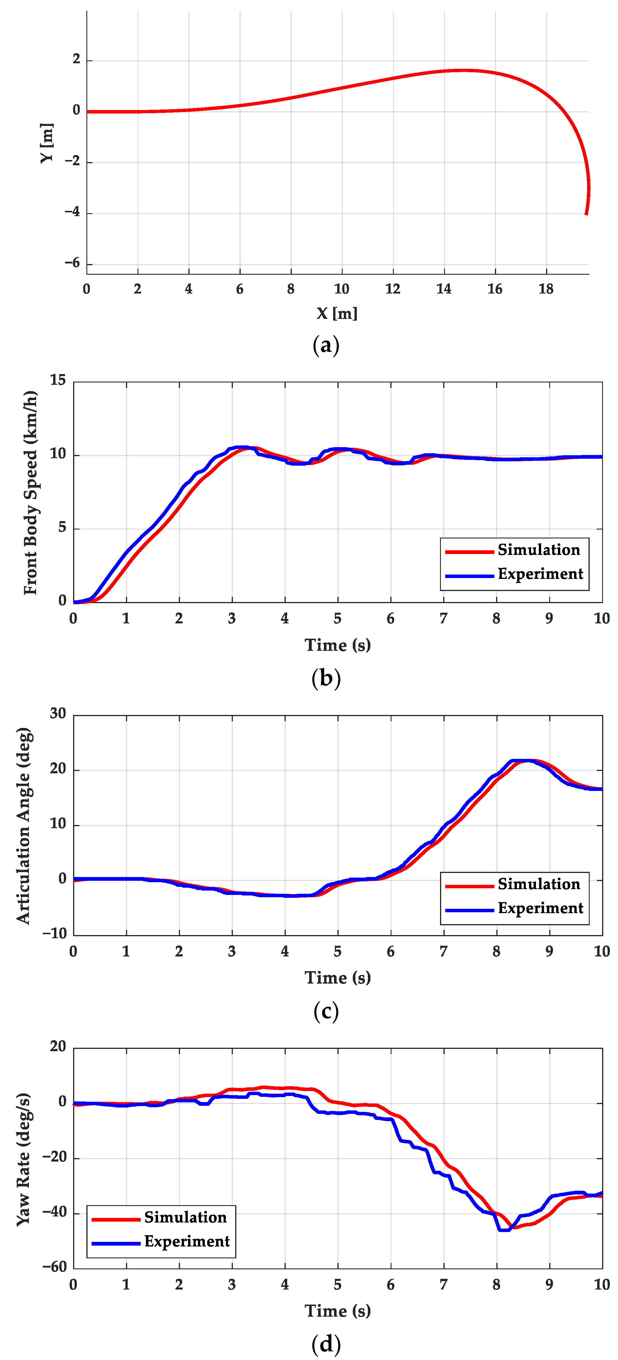
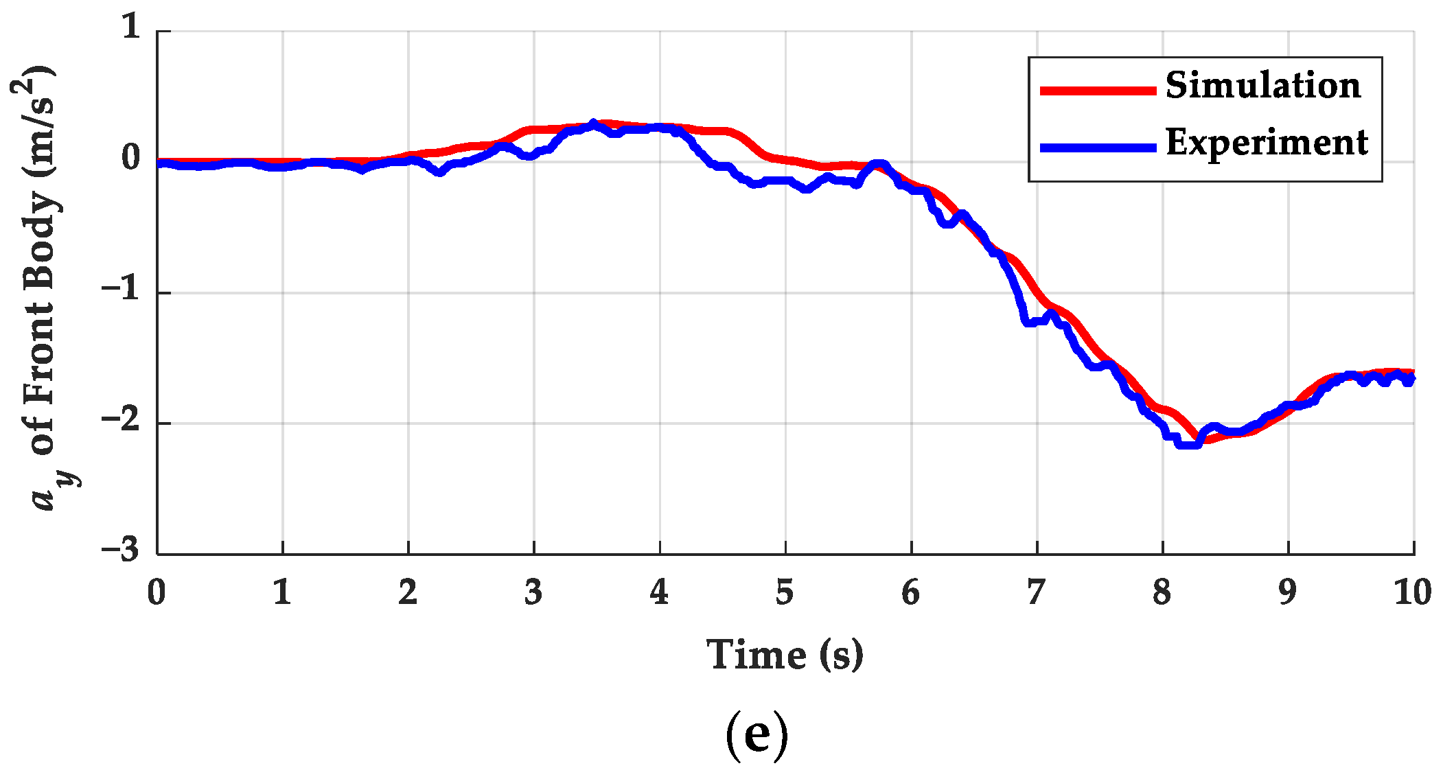
A validation of the vehicle model for MPC should precede any simulation study. Experimental results from a right-turn scenario are used to assess the modeling error of the vehicle model. Experimental data were obtained using an autonomous electric road sweeper developed jointly by the Korea Institute of Industrial Technologies (KIIT) and AM Special Vehicle (AMSV) in 2019 [36]. This autonomous electric road sweeper utilized the AFS mechanism for vehicle steering, while IMU and DGPS systems were employed to measure the vehicle’s accurate states. Additionally, an encoder was incorporated into the articulation joint to measure the articulation angle. Figure 3 illustrates both the experimental and simulation results for this right-turn scenario. As depicted in Figure 3, the simulation results obtained from the kinematic vehicle model closely match the experimental results. However, there are phase delays in speed and articulation angle between the experiment and simulation, as shown in Figure 3b,c. Yaw rate and lateral acceleration, illustrated in Figure 3d,e, exhibit errors resembling white noise. Therefore, we model the yaw rate and acceleration modeling errors as Gaussian white noise.

4.4. Base Algorithms

In this study, base algorithms were employed. Given that the AFS mechanism can be approximated as front wheel steering, both the pure pursuit and Stanley methods were selected as base algorithms. The outputs from these two methods are utilized as desired articulation angles for the plant model. However, conventional path tracking algorithms are typically designed under the assumption of front wheel steering. Consequently, parameters for these base algorithms had to be redefined to align with the characteristics of an AAV. As illustrated in Figure 4, the AFS mechanism can be transformed into a front wheel-steering vehicle with a variable wheelbase. Pf,v(xf,v, yf,v) represents the position of the virtual front axle.
Thus, the instance wheelbase Linst with articulation angle γ, is calculated, as follows:
L i n s t = L f cos γ + L r
When applying the (29) in pure pursuit controller, the articulation angle of the previous sampling time is used to approximate Linst to avoid the recursive formula. The Stanley method for the AAV employs the modified cross-track error, defined as the minimum distance between the target path and Pf,v(xf,v, yf,v). Further details of the pure pursuit and Stanley methods are provided in [37,38].
The distinctive mechanism and structure of the AAV could potentially lead to performance degradation in path tracking algorithms originally designed for front wheel steering. Consequently, an adaptive controller is chosen as another base algorithm to address the limitations associated with approximating front wheel steering. This adaptive controller, operating independently of a vehicle model, is referred to as a model-free controller. The design of this model-free controller is based on the assumption that changes in yaw rate in response to the vehicle’s steering angle can be modeled as a first-order delay system. Essentially, lateral dynamics are assumed to follow a first-order delay model, as follows:
θ ˙ r = λ τ s + 1 γ
To consider the structure of the AAV, the θ ˙ r and γ are used as the yaw rate and steering angle of the vehicle, respectively. λ and τ are the adaptive yaw rate gain and time constant of the yaw rate generation delay. As shown in (30), the simplified lateral dynamics does not take the vehicle model into account. Instead, λ is adapted to minimize the θ ˙ r error, as follows:
λ ^ = k γ θ ˙ r , d e s θ ˙ r
where θ ˙ r , d e s is the desired yaw rate of the AAV’s rear body. Based on (31), the articulated angle command is calculated, as follows:
γ = 1 λ ^ θ ˙ r , d e s + τ θ ¨ r , d e s
The θ ˙ r , d e s should be defined first to apply the model-free path tracking controller. In this study, the results of the reference state decision module were utilized to define the θ ˙ r , d e s . Since the reference state decision module determined the reference state of the front body, the relationship between front and rear bodies given in (9) was used to derive the θ ˙ r , d e s . The final base algorithm, denoted as ‘MPC’ in subsequent results, is designed using the same linear MPC framework as the proposed algorithm. However, this MPC controller is configured without the robust control method. In other words, no uncertainty tube is defined for the state vector. Thus, the base MPC only used u (k) to track the same reference state of the tube-based MPC.
The pure pursuit, Stanley method, and model-free controller all calculate the desired articulation angle. As discussed earlier in Section 5.1, the actuator for the articulation angle is modeled as a hydraulic cylinder. Consequently, an additional lower-level controller is introduced to determine the pressure command for this hydraulic cylinder. The pressure command is computed using a PID controller to minimize the articulation angle error. For longitudinal motion, the base algorithms require an additional controller to track the desired velocity. This velocity error is also regulated by a PID controller. Therefore, the actuator input required to track the output of these base algorithms can be determined, as follows:
e γ = γ ˙ d e s γ ˙ p d e s = K P , γ e γ + K I , γ e γ d t + K D , γ e ˙ γ e v = v d e s v f τ d e s = K P , v e v + K I , v e v d t + K D , v e ˙ v

5. Results

5.1. Simulation Model and Environment

The effectiveness of the proposed path tracking controller has been assessed through a simulation study. Simulations were conducted in two scenarios: one with sensor measurement noise and one without, to evaluate the robustness of the proposed method. To collectively consider the impact of model errors, a different model, distinct from the vehicle model used in MPC, was employed as the plant model for simulation. This plant model is designed based on the nonlinear dynamic bicycle model, incorporating the STI tire model. The actuator for the articulation joint is modeled with second-order dynamics to account for the stiffness and damping of the hydraulic cylinder. For longitudinal motion, the longitudinal tire force from the STI model served as an input for wheel dynamics at each axle [39]. In this case, first-order dynamics were added to the wheel dynamics input to account for the actuation delay of the powertrain and brake system. Additional details about this simulation model can be found in [40]. The simulations of the plant model and controller were implemented using MATLAB/Simulink. Since the proposed MPC is designed using linearized discrete vehicle models, it formulates an MPC problem as a linear quadratic problem. For this study, the CVXGEN solver was utilized to implement this MPC problem within the MATLAB/Simulink environment [41].

5.2. Simulation Results

A simulation study was conducted to assess the robustness of the proposed algorithm. The target path for this study was designed as an S-shaped path, comprising straight lines and arcs. Path tracking algorithms typically face challenges when encountering sudden changes in road curvature. To examine the algorithm’s response to such scenarios, segments of the target path were directly connected, creating discontinuous curvature changes. Specifically, two arcs with a radius of 4 m were linked to form the S-shaped path, with a straight road connected before and after these arc segments. The point where these two arcs meet exhibits the most abrupt curvature change. This target path is represented as a solid black line in Figure 5a.
The desired velocity for longitudinal motion was set at 4 m/s, a speed at which an AAV is prone to rollovers. To assess the potential for rollovers in AAVs, a Load Transfer Ratio (LTR) is employed as an index. LTR is computed from each tire’s vertical force, making it applicable to various vehicle types. Rollovers can occur if either of the two bodies of the vehicle rolls over; therefore, LTR was calculated for both bodies, as follows:
LTR i = F z i , L F z i , R F z i , L + F z i , R , i = f , r
where Fzi,L and Fzi,R means the vertical tire force of the left and right tires, respectively. The subscribe f and r indicate the front and rear bodies. A total of eight Key Performance Indices (KPIs) are defined to evaluate the path tracking performance. These include the mean, standard deviation, and maximum value of the lateral and heading errors, as well as the maximum of the lateral acceleration and LTR.
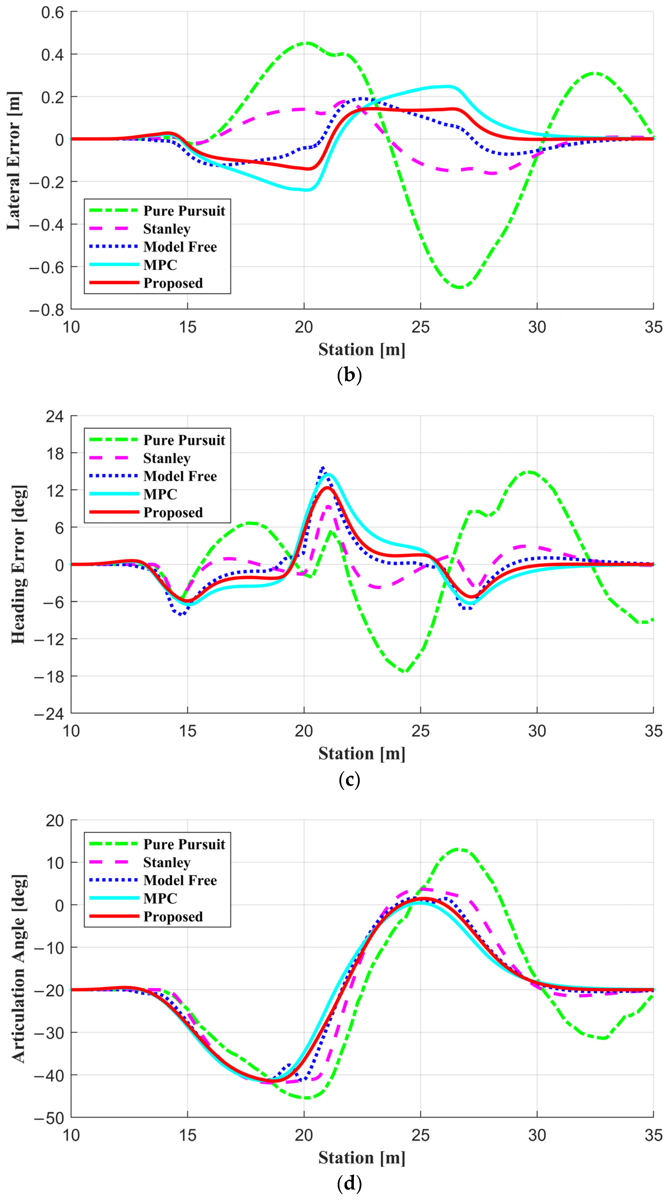
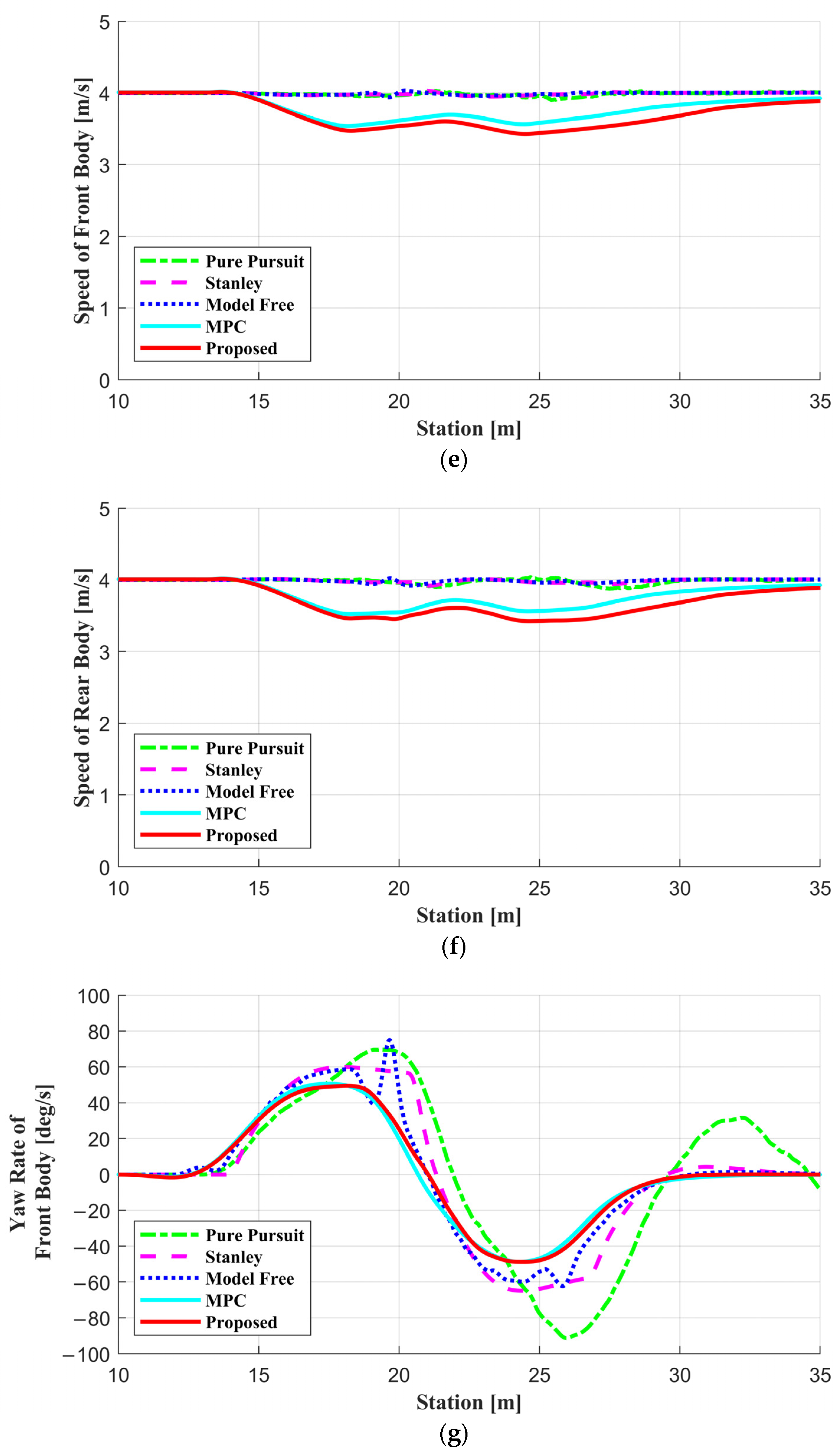
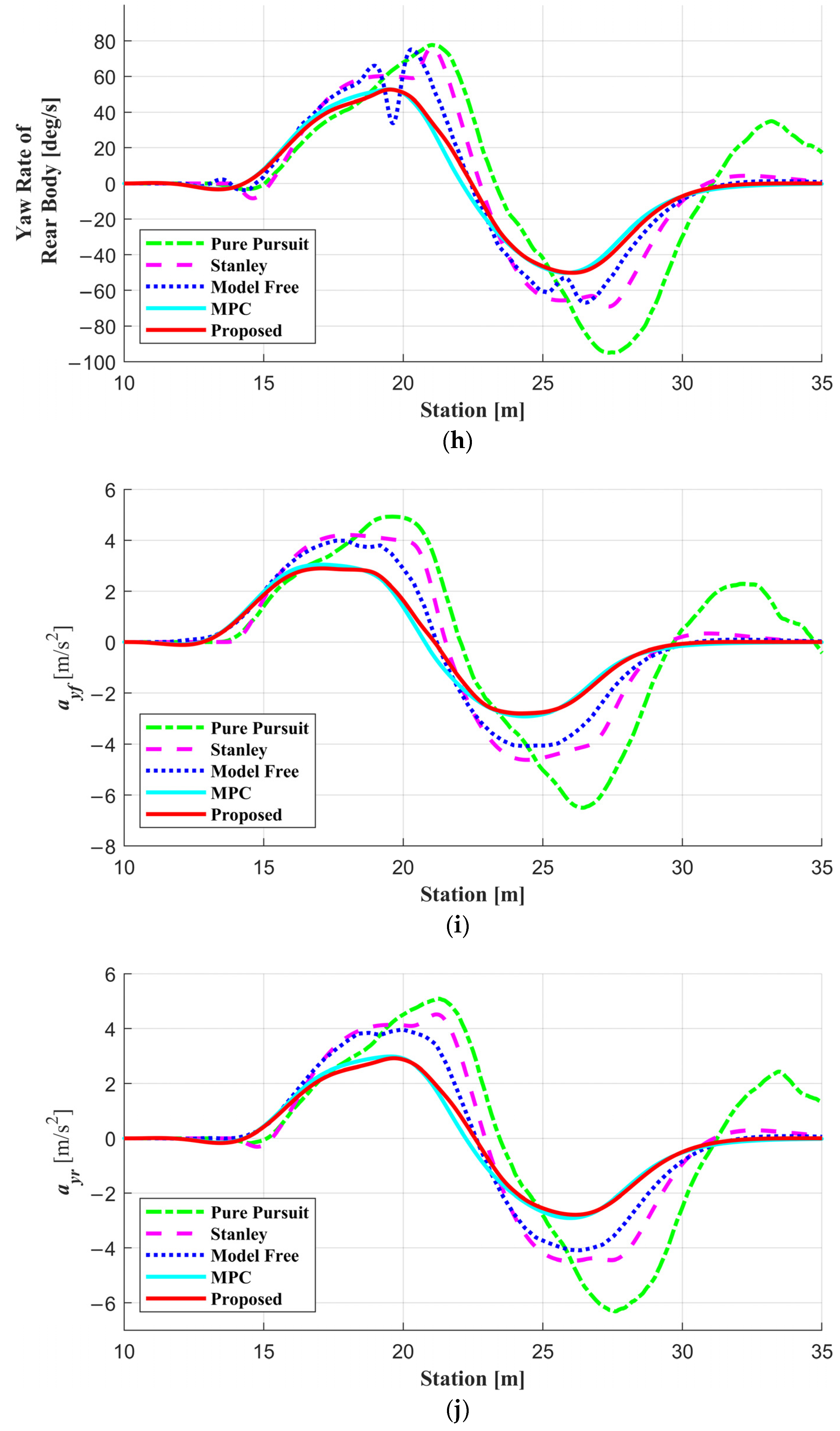
Figure 5 illustrates the simulation results for a noise-free scenario. The road friction coefficient is set to 0.85, simulating conditions where a rollover could potentially occur. In cases of low road friction coefficients, sufficient tire force to cause a rollover cannot be generated. Figure 5a describes the trajectory of each algorithm, showing the history of Pf(xf, yf). All algorithms used in this study successfully followed the target path, with trajectories closely matching the target path, except for the pure pursuit method. The pure pursuit controller exhibited significant overshooting, deviating outside the target path due to its inherent vulnerability to different AAV structures. As mentioned in Section 4.4, an AAV’s effective wheelbase depends on its articulation angle, making pure pursuit controllers less effective on high-curvature roads that require large articulation angles for the desired yaw motion. In contrast, both the Stanley method and model-free controllers do not consider wheelbase when determining the articulation angle, and they outperformed pure pursuit in this scenario. Both pure pursuit and Stanley methods, relying on single preview points, often resulted in vehicles driving along the inner corners of their target paths. However, actuation delays resulted in slow responses in articulation, causing vehicle trajectories to deviate outward from their paths when following second arcs. In contrast, by adjusting the yaw rate gain, model-free controllers significantly improved path tracking performance, compared to both pure pursuit and Stanley methods.
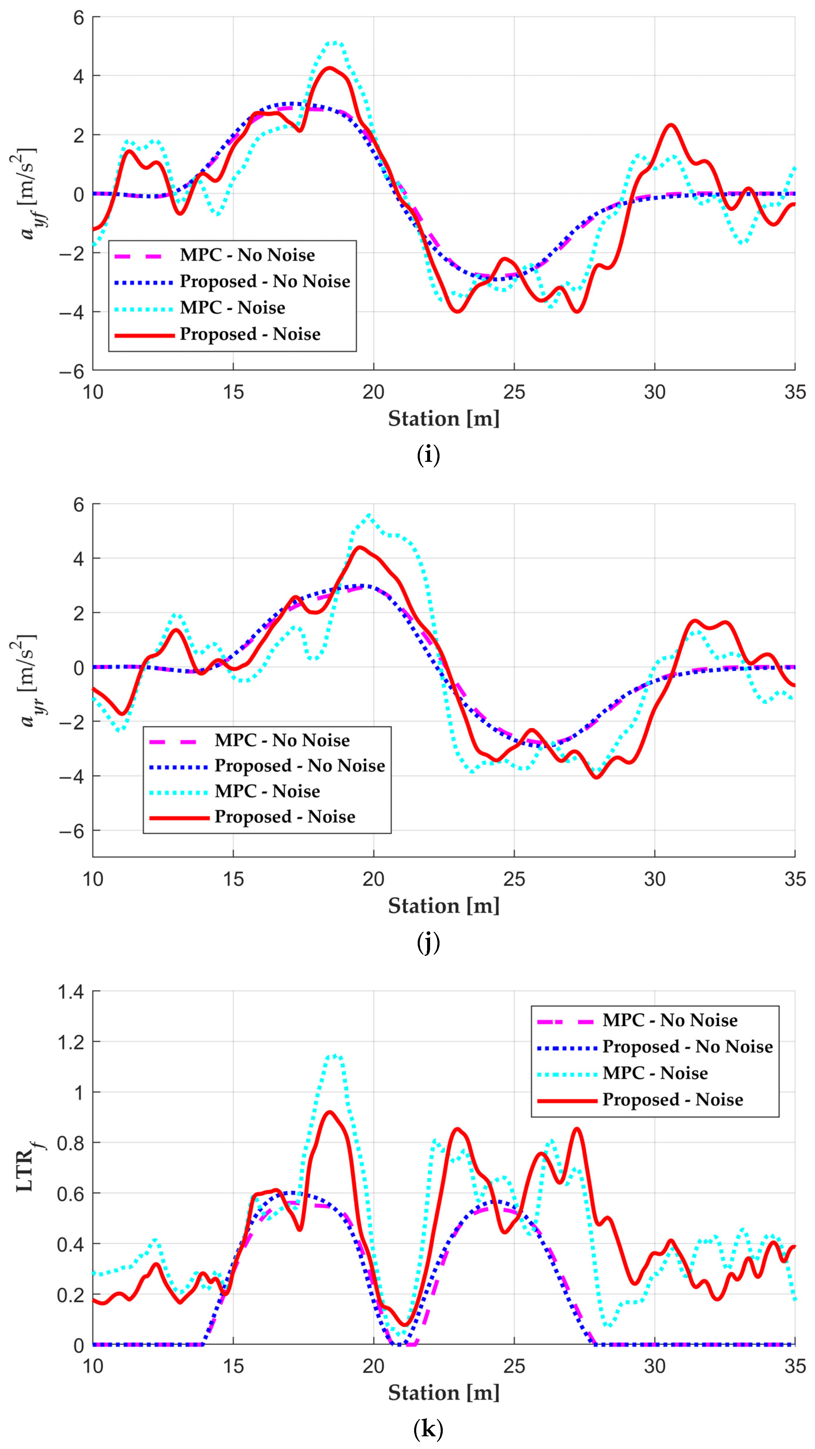
The simulation results for both the MPC and the proposed algorithm were quite similar. This similarity arises because no noise was introduced into the simulation, making it challenging for these two MPC-based controllers to exhibit performance differences related to robustness. As a result, as depicted in Figure 5b–d, the lateral and heading errors, as well as the articulation angle, displayed similar values, except for those from the pure pursuit method. However, both the MPC and the proposed algorithm experienced slight deceleration when navigating curvy roads, as illustrated in Figure 5e,f. This occurred because the lateral acceleration reached the MPC constraints, as shown in Figure 5i,j. An examination of the LTR values in Figure 5k,l reveals that all controllers, except those based on MPC, had an LTR value exceeding 1, indicating a potential rollover. This is because the pure pursuit and Stanley methods are geometry-based path trackers. In other words, the dynamic behavior of the AAV, such as rollover, is not considered in the pure pursuit and Stanley methods. Even if the steering input is applied to the level that the vehicle will rollover, the steering input does not decrease. Similarly, the model-free controller only considers the relationship between yaw rate and steering input as a first-order delay model. Therefore, dynamic behaviors are not considered the same as geometry-based controllers in model-free controllers. In addition, an articulated vehicle without a steering axle cannot be restored to a stable condition without proper steering or velocity control, unlike a front wheel-steering vehicle. This also explains a situation in which the base algorithm cannot recover in a situation where a rollover is about to occur. Therefore, addressing AAVs’ vulnerability to rollovers becomes challenging without appropriate longitudinal controllers working in tandem. Nevertheless, under ideal simulation conditions, both the MPC and the proposed algorithm demonstrate similar performance, with constraints applied within the MPC to prevent rollovers.
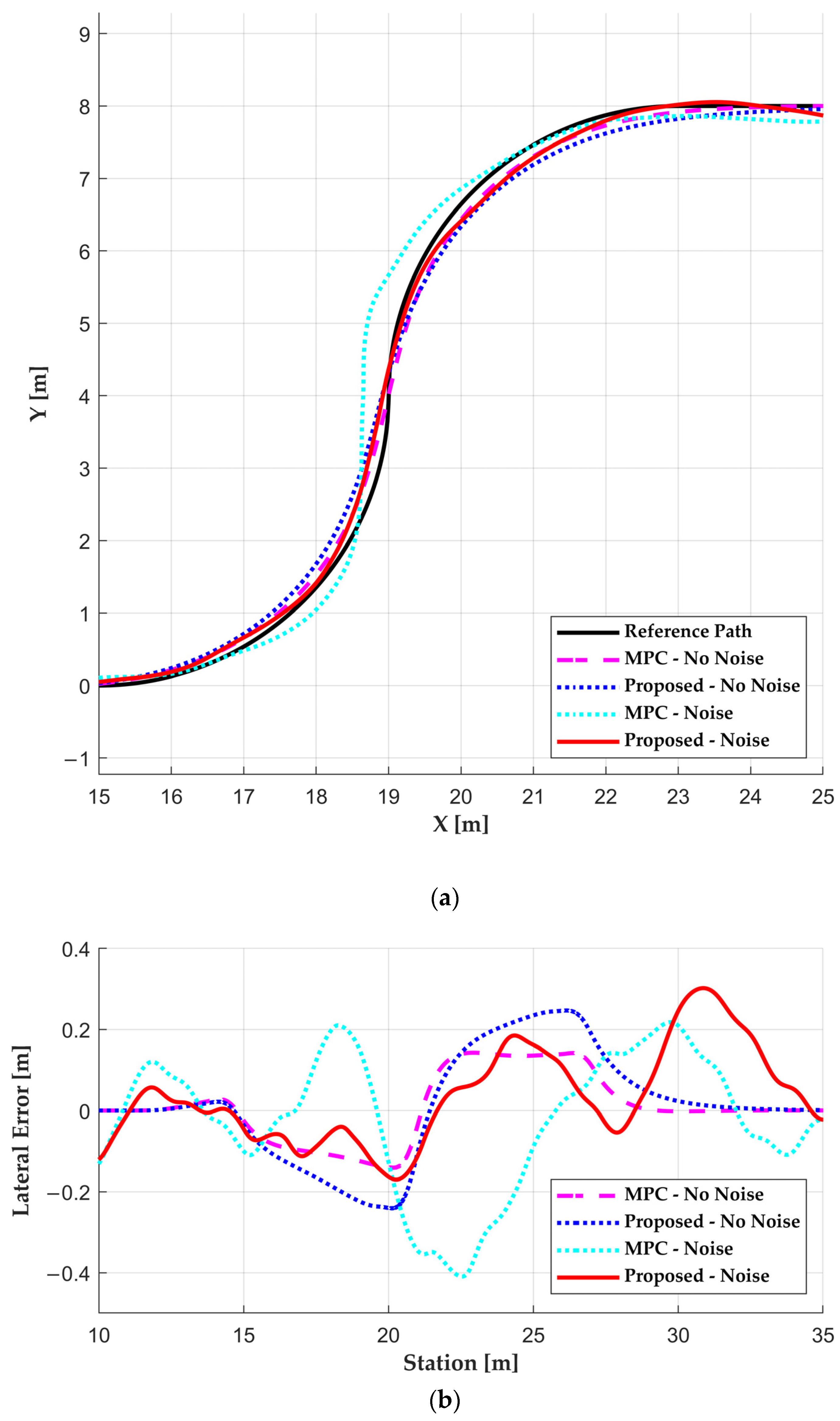
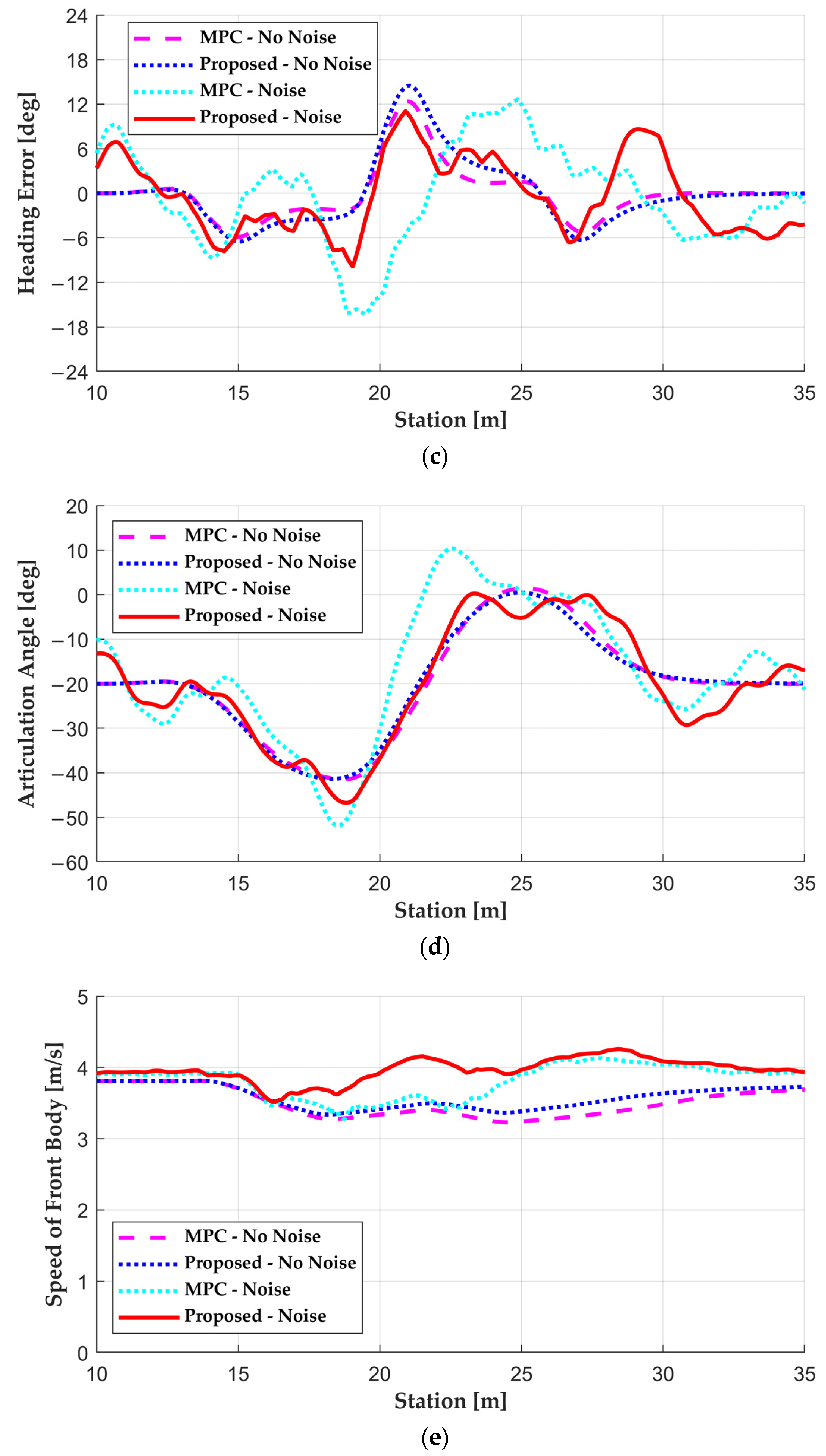
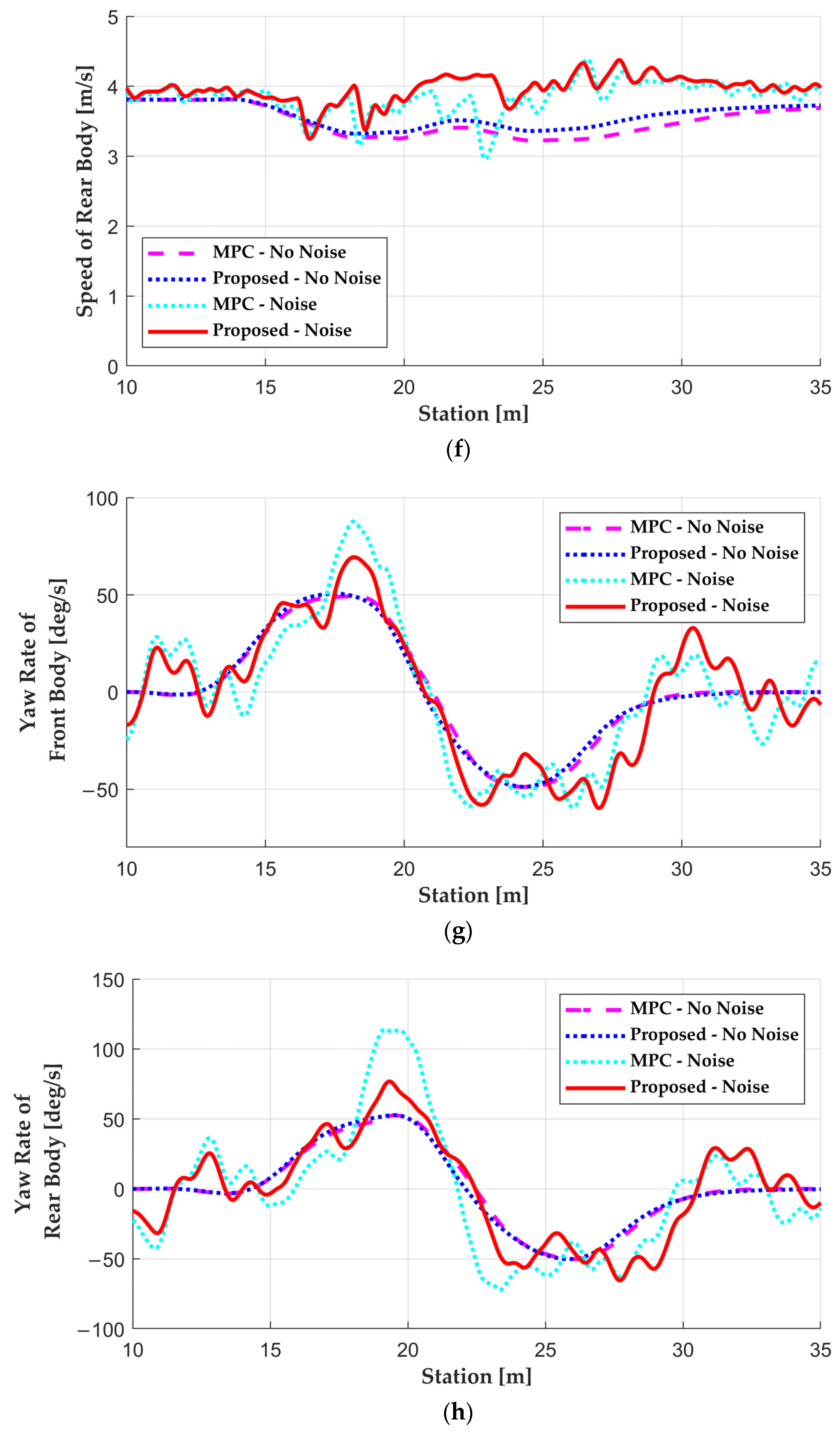
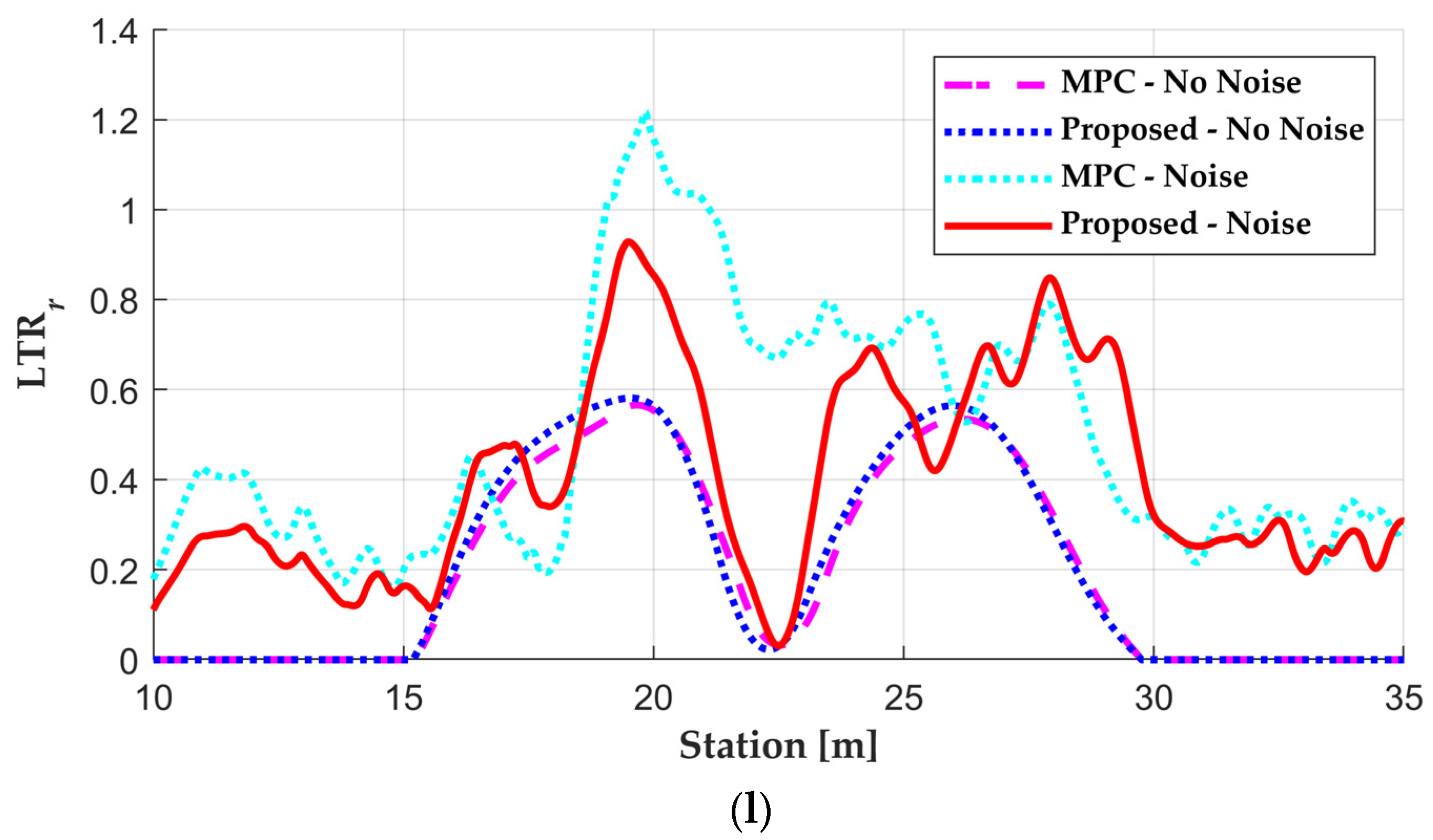
The simulation results of the noise injection case are summarized in Figure 6. In contrast to the simulation results without noise, the results of the base algorithms, except for MPC, were omitted due to their lack of robustness against disturbances, leading to controller divergence. Consequently, Figure 6 displays the results of MPC and the proposed algorithm for cases where noise was applied to the sensor measurement and the case where it was not. In Figure 6a, both MPC and the proposed algorithm can be observed to follow the target path without divergence, even with disturbances injected. Notably, the proposed algorithm exhibited a nearly identical driving trajectory to the noise-free case. However, MPC, which demonstrated similar performance to the proposed algorithm in the absence of noise, proved vulnerable to disturbances, resulting in significantly degraded performance in the noise case. This phenomenon becomes more pronounced in Figure 6b,c, which depict lateral and heading errors. The injected noise caused both algorithms to exhibit some level of vibration, but the proposed algorithm managed to keep the error within a range similar to that in the noise-free case. Similar trends were observed in parameters such as speed, yaw rate, and lateral acceleration. Nevertheless, when examining the LTR in Figure 6k,l, it becomes apparent that MPC, used as the base algorithm, exceeded a value of 1 in both LTRf and LTRr at the first corner. In contrast, the proposed algorithm effectively controlled the input to prevent rollover, even when exposed to high disturbances, confirming its robust control performance.
KPIs from the simulation results are summarized in Table 3. When considering scenarios without noise injection, the proposed algorithm showed KPIs related to lateral error compared to other base algorithms, except for pure pursuit. Notably, pure pursuit exhibited a mean and standard deviation of the lateral error nearly three times larger than the other algorithms. Regarding heading errors, the Stanley method showed the smallest mean and standard deviation, while the model-free controller and proposed controller exhibited similar values. Similar to lateral error, pure pursuit also showed the largest heading error, compared to other algorithms. Only considering the lateral and heading errors, the Stanley method provided the best performance among the base and proposed algorithms. However, when considering all KPIs, the proposed algorithm emerged as the top performer. For lateral stability and pure pursuit, the Stanley method and the model-free controller exhibited larger lateral acceleration, compared to MPC and the proposed algorithm. In comparison with MPC-based algorithms, the maximum lateral acceleration of other methods reached approximately 1.3 to 2 times that of MPC. This phenomenon stems from the limitation of determining control input by considering only a single position on the target path, unlike MPC, which factors in future vehicle motions. As indicated in Table 3, the increase in lateral acceleration corresponded to an increase in LTR. Even with no noise injection, only MPC and the proposed algorithm successfully kept the maximum LTR within 1, preventing rollovers.
KPIs for simulations with noise injection are also summarized in Table 3. Due to the divergence of the pure pursuit, Stanley, and model-free controllers when signal corruption occurred, their results are not included in Table 3. Comparing MPC and the proposed algorithm, the KPIs of the proposed algorithm delivered superior results. Hence, the proposed algorithm demonstrates robust path tracking performance while adhering to constraints.

6. Conclusions

An integrated controller for path tracking and velocity control is proposed to address the lateral stability of the AAV and enhance its resilience to external disturbances. This robust path tracking controller comprises two key modules: the reference state decision and tube-based MPC. In contrast to conventional approaches, the reference state decision module replaces error dynamics. It computes the reference state within the prediction horizon by integrating the kinematic vehicle model with the control input from the virtual controller. An LQR controller is employed to provide the optimal reference state. Tube-based MPC, the second component, calculates the optimal control input to track the reference state while adhering to state, input, and dynamic constraints. These constraints take into account factors like lateral stability and actuation limits, which can significantly affect performance. To evaluate the performance of the proposed robust path tracking controller, a simulation study was conducted. White noise was introduced to the measured signals from the plant model to assess robustness. The results demonstrated improved robustness and path tracking performance for the proposed algorithm, even under scenarios with measurement noise for multiple signals.
The motion control algorithm for the AAV can be improved in three ways. Firstly, replacing the kinematic vehicle model with a nonlinear dynamic model can significantly improve performance. Given that the AAV has non-steerable wheels, accounting for the non-negligible slip angle becomes crucial, especially as driving speeds increase. Therefore, designing a robust nonlinear controller is essential to extend the operational design domain of the AAV. Secondly, expanding the system to include more bodies is another potential improvement. For instance, adding an additional trailer to the rear body of the AAV requires the inclusion of a passive articulation joint. As a result, it becomes imperative to extend the applicability of the proposed algorithm to multi-trailer scenarios. Lastly, the implementation of the MPC and its testing on an actual AAV is a crucial step. This practical implementation allows for the validation and fine-tuning of the algorithm, ensuring that it works effectively in real-world AAVs.

Author Contributions

Conceptualization, T.L. and Y.J.; methodology, Y.J.; software, T.L. and Y.J.; validation, T.L. and Y.J.; formal analysis, T.L.; investigation, T.L.; resources, Y.J.; data curation, T.L.; writing—original draft preparation, Y.J.; writing—review and editing, Y.J.; visualization, T.L.; supervision, Y.J.; project administration, Y.J.; funding acquisition, Y.J. All authors have read and agreed to the published version of the manuscript.

Funding

This study was supported by the Research Program funded by the SeoulTech (Seoul National University of Science and Technology).

Data Availability Statement

Data are contained within the article.

Conflicts of Interest

The authors declare no conflicts of interest.

References

  1. Viscelli, S. Driverless? Autonomous Trucks and the Future of the American Trucker, Center for Labor Research and Education; University of California, Berkely and Working Partnerships USA: San Francisco, CA, USA, 2018. [Google Scholar]
  2. Rana, M.M.; Hossain, K. Connected and autonomous vehicles and infrastructures: A literature review. Int. J. Pavement Res. Technol. 2021, 16, 264–284. [Google Scholar] [CrossRef]
  3. Iclodean, C.; Cordos, N.; Varga, B.O. Autonomous shuttle bus for public transportation: A review. Energies 2020, 13, 2917. [Google Scholar] [CrossRef]
  4. Jo, A.; Lee, H.; Seo, D.; Yi, K. Model-reference adaptive sliding mode control of longitudinal speed tracking for autonomous vehicles. Proc. Inst. Mech. Eng. D J. Automob. Eng. 2023, 237, 493–515. [Google Scholar] [CrossRef]
  5. Zhang, Y.; Zhang, Y.; Ai, Z.; Feng, Y.; Zhang, J.; Murphey, Y.L. Estimation of electric mining haul trucks’ mass and road slope using dual level reinforcement estimator. IEEE Trans. Veh. Technol. 2019, 68, 10627–10638. [Google Scholar] [CrossRef]
  6. Hiraoka, T.; Nishihara, O.; Kumamoto, H. Automatic path-tracking controller of a four-wheel steering vehicle. Veh. Syst. Dyn. 2009, 47, 1205–1227. [Google Scholar] [CrossRef]
  7. Kang, J.; Kim, W.; Lee, J.; Yi, K. Design, implementation, and test of skid steering-based autonomous driving controller for a robotic vehicle with articulated suspension. J. Mech. Sci. Technol. 2010, 24, 793–800. [Google Scholar] [CrossRef]
  8. Yin, Y.; Rakheja, S.; Yang, J.; Boileau, P.E. Design optimization of an articulated frame steering system. Proc. Inst. Mech. Eng. D J. Automob. Eng. 2018, 232, 1339–1352. [Google Scholar] [CrossRef]
  9. Hang, P.; Chen, X.; Luo, F. LPV/H∞ controller design for path tracking of autonomous ground vehicles through four-wheel steering and direct yaw-moment control. Int. J. Automot. Technol. 2019, 20, 679–691. [Google Scholar] [CrossRef]
  10. Hiraoka, T.; Nishihara, O.; Kumamoto, H. Model-following sliding mode control for active four-wheel steering vehicle. Rev. Automot. Eng. 2004, 25, 305. [Google Scholar]
  11. Shamah, B.; Wagner, M.D.; Moorehead, S.; Teza, J.; Wettergreen, D.; Whittaker, W.L. Steering and control of a passively articulated robot. In Proceedings of the SPIE 4571, Sensor Fusion and Decentralized Control in Robotic Systems IV, Boston, MA, USA, 28–31 October 2001. [Google Scholar]
  12. Sunday, B. Stability analysis of a semi-trailer articulated vehicle: A review. Int. J. Automot. Sci. Technol. 2021, 5, 131–140. [Google Scholar]
  13. He, Y.; Khajepour, A.; McPhee, J.; Wang, X. Dynamic modelling and stability analysis of articulated frame steer vehicles. Int. J. Heavy Veh. Syst. 2005, 12, 28–59. [Google Scholar] [CrossRef]
  14. Lei, T.; Wang, J.; Yao, Z. Modelling and stability analysis of articulated vehicles. Appl. Sci. 2021, 11, 3663. [Google Scholar] [CrossRef]
  15. Shen, Y.; Xie, J.; Zhang, W. Study of hydraulic steering process for intelligent autonomous articulated vehicle. SAE Tech. Pap. 2018. [Google Scholar] [CrossRef]
  16. Sampei, M.; Tamura, T.; Kobayashi, T.; Shibui, N. Arbitrary path tracking control of articulated vehicles using nonlinear control theory. IEEE Trans. Control Syst. Technol. 1995, 3, 125–131. [Google Scholar] [CrossRef]
  17. Mohamed, A.; Ren, J.; Lang, H.; El-Gindy, M. Optimal path planning for an autonomous articulated vehicle with two trailers. Int. J. Autom. Control 2018, 12, 449–465. [Google Scholar] [CrossRef]
  18. Bolzern, P.; DeSantis, R.M.; Locatelli, A.; Masciocchi, D. Path-tracking for articulated vehicles with off-axle hitching. IEEE Trans. Control Syst. Technol. 1998, 6, 515–523. [Google Scholar] [CrossRef]
  19. Oreh, S.T.; Kazemim, R.; Azadi, S. A new desired articulation angle for directional control of articulated vehicles. Proc. Inst. Mech. Eng. K J. Multi-body Dyn. 2012, 226, 298–314. [Google Scholar] [CrossRef]
  20. Jeong, D.; Choi, S.B. Tube-based Robust Model Predictive Control for Tracking Control of Autonomous Articulated Vehicles. IEEE Trans. Intell. Veh. 2024, 9, 2184–2196. [Google Scholar] [CrossRef]
  21. Alshaer, B.J.; Darabseh, T.T.; Alhanouti, M.A. Path planning, modeling and simulation of an autonomous articulated heavy construction machine performing a loading cycle. Appl. Math. Model. 2013, 37, 5315–5325. [Google Scholar] [CrossRef]
  22. Meng, Y.; Gan, X.; Wang, Y.; Gu, Q. LQR-GA controller for articulated dump truck path tracking system. J. Shanghai Jiaotong Univ. (Sci.) 2019, 24, 78–85. [Google Scholar] [CrossRef]
  23. Nayl, T.; Nikolakopoulos, G.; Gustafsson, T. Effect of kinematic parameters on MPC based on-line motion planning for an articulated vehicle. Robot. Auton. Syst. 2015, 70, 16–24. [Google Scholar] [CrossRef]
  24. Nayl, T.; Nikolakopoulos, G.; Gustafsson, T. On-line path planning for an articulated vehicle based on model predictive control. In Proceedings of the 2013 IEEE international conference on control applications (CCA), Hyderabad, India, 28–30 August 2013. [Google Scholar]
  25. Nayl, T.; Nikolakopoulos, G.; Gustafsson, T. A full error dynamics switching modeling and control scheme for an articulated vehicle. Int. J. Control Autom. Syst. 2015, 13, 1221–1232. [Google Scholar] [CrossRef]
  26. Nayl, T.; Nikolakopoulos, G.; Gustafsson, T. Switching model predictive control for an articulated vehicle under varying slip angle. In Proceedings of the 2012 20th Mediterranean Conference on Control & Automation (MED), Barcelona, Spain, 3–6 July 2012. [Google Scholar]
  27. Marshall, J.; Barfoot, T.; Larsson, J. Autonomous underground tramming for center-articulated vehicles. J. Field Robot. 2008, 25, 400–421. [Google Scholar] [CrossRef]
  28. Rains, G.C.; Faircloth, A.G.; Thai, C.; Raper, R.L. Evaluation of a simple pure pursuit path-following algorithm for an autonomous, articulated-steer vehicle. Appl. Eng. Agric. 2014, 30, 367–374. [Google Scholar]
  29. Yao, D.; Xie, H.; Qiang, W.; Liu, Y.; Xiong, S. Accurate trajectory tracking with disturbance-resistant and heading estimation method for self-driving vibratory roller. IFAC-PapersOnLine 2018, 51, 754–758. [Google Scholar] [CrossRef]
  30. Liu, Z.; Yue, M.; Guo, L.; Zhang, Y. Trajectory planning and robust tracking control for a class of active articulated tractor-trailer vehicle with on-axle structure. Eur. J. Control. 2020, 54, 87–98. [Google Scholar] [CrossRef]
  31. Gao, Y.; Cao, D.; Shen, Y. Path-following control by dynamic virtual terrain field for articulated steer vehicles. Veh. Syst. Dyn. 2020, 58, 1528–1552. [Google Scholar] [CrossRef]
  32. Li, X.; Gong, X.; Huang, J.; Chen, Y.H. Trajectory-tracking controller for vehicles on inclined road based on Udwadia–Kalaba equation. Green Energy Intell. Transp. 2022, 1, 100021. [Google Scholar] [CrossRef]
  33. Fong, J.; Tan, Y.; Crocher, V.; Oetomo, D.; Mareels, I. Dual-loop iterative optimal control for the finite horizon LQR problem with unknown dynamics. Syst. Control Lett. 2018, 111, 49–57. [Google Scholar] [CrossRef]
  34. Lee, C.; Van Tran, Q.; Kim, J. Robust Path Tracking and Obstacle Avoidance using Tube-based Model Predictive Control for Surface Vehicles. IFAC-Pap. 2022, 55, 301–306. [Google Scholar] [CrossRef]
  35. Youness, G.; Phan, N.U.T.; Boulakia, B.C. BootBOGS: Hands-on optimizing Grid Search in hyperparameter tuning of MLP. In Proceedings of the AICCSA 2023: 20th ACS/IEEE International Conference on Computer Systems and Applications, Giza, Egypt, 4–7 December 2023. [Google Scholar]
  36. Korea IT News. Gwangju-Si and Korea Institute of Industrial Technology to Introduce Two Unmanned Special Vehicles Next Month. Available online: https://english.etnews.com/20201118200004 (accessed on 20 November 2020).
  37. Coulter, R. Implementation of the Pure Pursuit Path Tracking Algorithm; Carnegie Mellon University: Pittsburgh, PA, USA, 1990; pp. 1–9. [Google Scholar]
  38. Thrun, S.; Montemerlo, M.; Dahlkamp, H.; Stavens, D.; Aron, A.; Diebel, J.; Fong, P.; Gale, J.; Halpenny, G.; Lau, K.; et al. Stanley: The robot that won the DARPA Grand Challenge. J. Field Robot. 2006, 23, 661–692. [Google Scholar] [CrossRef]
  39. Liu, Q.; Solis, D.; Pan, W. Analysis of the STI tire Model. SAE Tech. Pap. 2002. [Google Scholar] [CrossRef]
  40. Jeong, Y. Integrated Vehicle Controller for Path Tracking with Rollover Prevention of Autonomous Articulated Electric Vehicle Based on Model Predictive Control. Actuators 2023, 12, 41. [Google Scholar] [CrossRef]
  41. Mattingley, J.; Boyd, S. CVXGEN: A code generator for embedded convex optimization. Optim. Eng. 2012, 13, 1–27. [Google Scholar] [CrossRef]
Figure 1. The overall architecture of the proposed algorithm.
Actuators 13 00164 g001
Figure 2. Parameter definition for the vehicle model of the AAV.
Actuators 13 00164 g002
Figure 3. Comparison between the simulation results of the kinematic vehicle model and experimental results: (a) trajectory of the simulation result; (b) speed of the front body; (c) articulation angle; (d) yaw rates of the front body; (e) lateral accelerations of the front body.
Actuators 13 00164 g003aActuators 13 00164 g003b
Figure 4. The virtual front axle.
Actuators 13 00164 g004
Figure 5. Simulation results of noise-free case: (a) driving trajectory; (b) lateral error; (c) heading angle error; (d) articulation angle; (e) speed of the front body; (f) speed of the rear body; (g) yaw rate of the front body; (h) yaw rate of the rear body; (i) lateral acceleration of the front body; (j) lateral acceleration of the rear body; (k) LTR of the front body; (l) LTR of the rear body.
Actuators 13 00164 g005aActuators 13 00164 g005bActuators 13 00164 g005cActuators 13 00164 g005dActuators 13 00164 g005e
Figure 6. Simulation results of noise case: (a) driving trajectory; (b) lateral error; (c) heading angle error; (d) articulation angle; (e) speed of the front body; (f) speed of the rear body; (g) yaw rate of the front body; (h) yaw rate of the rear body; (i) lateral acceleration of the front body; (j) lateral acceleration of the rear body; (k) LTR of the front body; (l) LTR of the rear body.
Actuators 13 00164 g006aActuators 13 00164 g006bActuators 13 00164 g006cActuators 13 00164 g006dActuators 13 00164 g006e
Table 1. Noise specification.
VariableStandard DeviationVariableStandard Deviation
xf0.5 mvf1 m/s
yf0.5 maf0.2 m/s2
θf5 degγ0.5 deg
Table 2. Parameters for AAV and the proposed algorithm.
ParameterValueParameterValue
Lf0.605 mΔT0.1 s
Lr0.895 mNp20
τf0.2 sτa0.05 s
Qx1xmgn0.5 m
Qy75ymgn0.5 m
Qθ100θmgn3 deg
Qv10vf,min0 m/s
Qa20vf,max5 m/s
Qγ100af,min−3 m/s2
Q γ ˙ 150af,man1 m/s2
Rp0.1γman50 deg
Rτ0.01 γ ˙ max 90 deg/s
pmax50 barτmax1500 Nm
Table 3. KPIs of the simulation results.
CriteriaNoisePure PursuitStanleyModel-MPCProposed
Mean (SD) of lateral error [m]Off0.1660
(0.1975)
0.0422
(0.0585)
0.0389
(0.0530)
0.0696
(0.0893)
0.0447
(0.0568)
On---0.1286
(0.0983)
0.0863
(0.0702)
Max of lateral error [m]Off0.69830.17700.19010.24700.1429
On---0.40930.3022
Mean (SD) of heading error [deg]Off4.3795
(4.8417)
0.9832
(1.6004)
1.3902
(2.7911)
2.2949
(3.1920)
1.7151
(2.6232)
On---4.8468
(3.8542)
3.7865
(2.4860)
Max of heading error [deg]Off17.49519.339015.749214.468612.3413
On---16.265811.0544
Max of ay [m/s2]Off5.86214.64364.27333.04352.9409
On---5.56994.3923
Max of LTROff1.78611.42521.25650.91390.8942
On---1.21750.9284
Disclaimer/Publisher’s Note: The statements, opinions and data contained in all publications are solely those of the individual author(s) and contributor(s) and not of MDPI and/or the editor(s). MDPI and/or the editor(s) disclaim responsibility for any injury to people or property resulting from any ideas, methods, instructions or products referred to in the content.