1. Introduction
Unwanted vibrations can cause significant problems for various systems and structures, and engineering principles must be employed to address them. Various sources, including machines, transportation, seismic activity, and human activity, can cause vibrations. The effects can be severe, ranging from damage to structures to malfunctioning sensitive equipment and processes. The goal of vibration isolation is to minimize or eliminate the transmission of vibrations from one system or component to another, thereby preserving the affected elements’ integrity, performance, and functionality. Many types of engineering applications require vibration isolation. In industrial settings, heavy machinery can generate vibrations that may compromise nearby structures or affect the precision of delicate manufacturing processes. Vehicles and aircraft also create vibrations that can cause problems for passengers or sensitive equipment. In electronics, the performance of delicate instruments and devices can be significantly impacted by vibrations, leading to reduced accuracy or malfunction. To address these challenges, engineers use various techniques and technologies for vibration isolation. These may include isolators, dampers, and resilient materials designed to absorb, dissipate, or redirect vibrational energy. The field of vibration isolation encompasses both active [
1,
2,
3,
4,
5,
6] and passive methods [
7,
8,
9,
10,
11,
12], each with advantages and limitations. Active vibration control requires a power source, a feedback sensor, and a controller to generate and regulate the control force or moment. This technique has a broader operation bandwidth and can achieve multiple objectives simultaneously. Nevertheless, active vibration control has some drawbacks, namely, high cost, complexity, energy consumption, and stability and robustness issues. On the contrary, passive vibration control involves adding or modifying elements in the system, such as springs, dampers, masses, or isolators, to change its natural frequency, damping ratio, or mode shape. Passive vibration control does not require any external power source, feedback sensor, or controller. It is relatively cheap, easy to implement, and robust to uncertainties and disturbances. However, passive vibration control has some limitations, such as low effectiveness at high frequencies, narrow bandwidth of operation, and trade-off between stiffness and damping.
In the last ten years, the capacity of phononic crystals to manipulate elastic waves has captured the interest of many researchers. The ability to forbid propagation in some frequency range for elastic waves (i.e., bandgap) has numerous applications in different fields, including vibration suppression. For example, Meng [
13] indicated that the transmission of waves in particular frequency ranges and phononic band gaps can be obstructed through phononic crystals and metamaterials. The extension of band gaps in these materials is attributed to block mass variations. The design proposed, which is nearly periodic, is based on cuboid blocks connected by curved beams. The blocks have internal voids that adjust the local masses and generate a 3D rainbow phononic crystal. The results reveal that the proposed approach can create lightweight phononic crystal with a simple and manufacturable design. The attenuation bandwidths of these phononic crystals surpass those of equivalent periodic designs with equal mass, exhibiting more than twice the effectiveness. Shao [
14] conducted a simulation and experimental investigation on the vibration reduction of low-frequency honeycomb phononic crystals. The results suggest that the honeycomb phononic crystal is a noteworthy solution for reducing vibration, particularly at lower frequencies. The authors designed a honeycomb phononic crystal using a chemigum plate and a steel column, calculated the bandgaps, and analyzed the vibration modes. The results showed that the honeycomb phononic crystal reduced vibration by up to 60 dB in the frequency range of 600–900 Hz, while a rubber plate only reduced it by about 20 dB. Yang et al. [
15] described low-frequency elastic waves and vibration control mechanism of innovative phononic crystal thin plates. The plate is shown to have good band gap tuning and vibration attenuation effects. An innovative phononic crystal thin plate is proposed for controlling low-frequency vibration in practical engineering. Peng et al. [
16] stated that in this article, the method of modeling, operating principle, and recommended specifications for acoustic metamaterial plates with multiple stopbands are presented. The metamaterial plate is designed to reduce vibrations by incorporating a two-degree of freedom mass-spring system within an isotropic plate. The metamaterial plate employs the principles of traditional vibration absorbers, as indicated by the results obtained. The stopbands’ bandwidth can be increased by adjusting the absorber mass and the average mass of the isotropic plate. The paper also discusses the importance of damping ratios for quick response and wide stopbands. A sensitivity analysis on absorber resonant frequencies reveals significant sensitivity in the stopband regions. Wei [
17] reported the vibration attenuation of 2D rainbow metamaterial plates with spatially varying stepped resonators. It is found that rainbow resonators can lead to broader vibration attenuation bands compared to periodic resonators. The additional mode shapes of the rainbow resonators break the complete bandgap of the periodic metamaterial plate into isolated narrower bandgaps, resulting in reduced vibration of the host plates. Broadening the attenuation band by nonperiodicity could help design plate structures with better vibration attenuation. The study also discusses the existence of bandgaps in elasto-acoustic metamaterials and the potential for vibration attenuation at low frequencies. The paper proposes metamaterial plates with rainbow-stepped resonators for obtaining broader vibration attenuation bands. The dynamic properties of periodic and rainbow metamaterial plates are compared, and it is concluded that the nonperiodic resonators’ varied resonance frequencies contribute to the attenuation band’s broadening. The study suggests that the investigated metamaterial plate can be extended to broader applications and provides data availability information.
With the latest scientific developments, membrane-type acoustic metamaterials have recently garnered significant attention. Yang [
18] unveiled a novel concept of negative dynamic mass that indicates a phase difference between force and acceleration. These materials demonstrate macroscopic behaviors beyond classical acoustics by negating the Newtonian assumptions. The fundamental building block of these materials is a circular elastic membrane with a fixed boundary. The authors have successfully utilized stacked membrane-type panels with varying operating frequencies to achieve optimal effectiveness across various frequencies. Given the weak elastic moduli of the membrane, small and finite samples can produce distinct low-frequency oscillation patterns. These findings hold substantial implications for the design and development of future acoustic metamaterials. Afterwards, scientists suggested other techniques for designing acoustic metamaterials to enhance their ability to insulate low-frequency sounds. They achieved strong and broad sound insulation in the low-frequency range [
19,
20,
21,
22,
23,
24,
25,
26].
In addition to excellent sound insulation, membrane resonators show potential applications as vibration isolators. Like in the sound isolation case, low elastic moduli shift resonance frequency to lower frequencies. Sun et al. [
27] reported the experimental realization of the decorated membrane resonator, which offers a lightweight, compact, and effective low-frequency damper. Two dampers can significantly reduce the vibration amplitude at around 150 Hz with a weight of 0.6% of the host structure. According to a research study by Gao et al. [
28], important design principles have been identified for the bilayer membrane-type metamaterial. By increasing the mass values of resonators and applying tensile stresses to membranes in each unit cell, the bandgap width can be expanded. Conversely, changing the periodicity of the unit cell has the opposite effect. In another study, Dong and colleagues [
29] suggested a new metamaterial plate with double-mass membrane-type resonators (DMMRs). The results indicate that the suggested metamaterial plate possesses multiple band gaps caused by the cancellation of the shear forces in the plate by the reaction forces produced by the first two resonances of the resonators. The research suggests that the presence and size of the two band gaps are strongly linked to the mass ratio between the resonator and the host plate. In another study, Sun [
30] described an experimental investigation of a vibration damper composed of acoustic metamaterials. This paper presents the experimental results of a vibration damper comprising acoustic metamaterials attached to a rectangular steel plate. The damper reduces vibrating plate resonance magnitudes by up to 42 dB and provides an overall vibration reduction of 24.7 dB in the 100–1200 Hz frequency range. The damper shows potential for use in aerospace vehicles. Comparison experiments with a commercial rubber plate show that the acoustic metamaterial structure performs better in lower and higher frequency ranges. Shen et al. [
31] discuss phononic crystals and a periodic pipe structure to control vibrations in piping systems. The calculations are based on the Timoshenko beam model and the Bragg scattering mechanism of phononic crystals. The results show that the vibration band gaps effectively attenuate vibrations. The research provides a reference for the design and vibration control of liquid-filled composite pipelines. The paper also calculates the band structure of flexural, longitudinal, and torsional vibrations using the transfer matrix method. The results demonstrate the existence of vibration band gaps in a 3D periodic pipe structure. The paper emphasizes the importance of considering shear distortion and section moment of inertia in accurately calculating flexural vibration frequency response functions. The density, Young’s modulus, and shear modulus of epoxy and steel are provided to calculate the band structures of a straight periodic pipe. Understanding the vibration properties of this system is crucial. Manushyna et al. [
32] studied the application of vibroacoustic metamaterials for structural vibration reduction in space structures. The technology of vibroacoustic metamaterials is applied to representative scaled-down launchers and satellite components. It was shown to lower vibrations across a broad spectrum of frequencies, which is beneficial for handling. Moreover, vibroacoustic metamaterials make using composite materials for rocket components possible. According to Janssen et al. [
33], vibroacoustic metamaterials that are locally resonant are effective in reducing noise and vibration; however, these materials often experience a significant drop in performance after achieving peak insulation, which limits their usefulness. To break the limitation, a multiresonant metamaterial panel was developed and compared to a conventional panel, demonstrating improved performance after the peak insulation. Ma et al. [
34] suggested a technique to dampen low-frequency vibrations using ultralight locally resonant plate-type units as dampers, which have a designable band gap property to absorb and localize structural vibration in a predefined band gap range. These dampers can be as light as 0.3% of the objective vibration structure, making them highly suitable for industry applications. Wang [
35] proposed a broadband damping method using multiple damping units to achieve vibration absorption across a wide frequency range. By integrating units with different frequency ranges, a linear superposition of the absorption bandwidth can be achieved, overcoming the limitations of traditional dynamic vibration absorbers or metamaterial dampers with narrow working bands. This design optimizes each subunit’s working bandwidth, significantly increasing the available design parameters. The damper device and subunits are small, resulting in lower additional mass compared to traditional dynamic vibration absorbers. The proposed method and device have potential applications in suppressing low-frequency vibrations in various machinery and equipment. Li and colleagues [
36] noted that a metamaterial plate with multi bandgaps is proposed for vibration suppression by integrating membrane-mass structures into a honeycomb sandwich structure. The proposed metamaterial exhibits excellent vibration suppression performance and designability. Yu and colleagues [
37] reported an integrated load-bearing vibration-isolation supporter with decorated metamaterial absorbers. Without altering the metallic support structure, a steel support column offers the necessary load-bearing rigidity. Additionally, some lightweight subwavelength local resonance units are integrated to prevent the propagation of elastic waves and absorb the vibration of the support structure. The vibration-absorbing unit’s band gap can be customized based on parameters such as the mass block radius, plate thickness, frame height, and beam width.
The aim of the current study is an experimental investigation of low-frequency vibration attenuation. The tubes with small diameters (outer diameter to 16 mm) used in different systems, for example, condition systems, are vulnerable to continuous low-frequency vibration, leading to fatigue. Due to this and the fact that it is not covered in the existing works, the authors propose the membrane resonator to suppress the vibration in tubes in the frequency range from 100 Hz to 150 Hz.
2. Dispersion Curves and Bandgap Configuration
The resonance of the mechanical system is described by a well-known Equation (1) that is suitable for the prediction of the first bandgap [
38]:
where
k—stiffness,
m—mass. To achieve low-frequency resonance, there are two possible approaches: decreasing the stiffness or increasing the mass. However, increasing the mass is unsuitable for the current case since the tubes are in focus, which are usually lightweight. The different types of silicone can provide the low stiffness required. Additionally, since the tube has axial symmetry, for the sake of simplicity, the resonator also has axial symmetry.
The first step of the study of the proposed resonator is in the dispersion curves calculation, which can show the frequency range where the propagation of the waves (longitudinal, torsional and flexural guided waves) is restricted; in other words, the waves have a bandgap. For that, the governing Equation (2) in eigenfrequency formulation (3) is used.
where
ρ—density,
u—displacement, ∇—nabla operator,
σ—stress tensor,
λ = −jω—eigenfrequency.
Threatening the resonator as an infinite chain of phononic crystals allows the application of the Floquet boundary condition and the calculation of wave behavior in the first irreducible Brillouin zone [
39]. Because of axial symmetry, geometry can be reduced from 3D to 2D axisymmetric, with a circumferential wavenumber equal to an integer number. By solving the eigenvalue problem, the dispersion curve can be obtained.
The described procedure was performed using commercial software COMSOL ver. 6.1 based on the finite element method. A copper tube was chosen as a host structure because of the wide range of usage. The silicone membrane resonator with an additional mass and a frame are attached to the tube. The material properties of copper and silicone are provided in
Table 1.
The hardness s of the silicone can be converted to Young’s modulus approximately by the Gent Equation (4) [
40] (result in MPa):
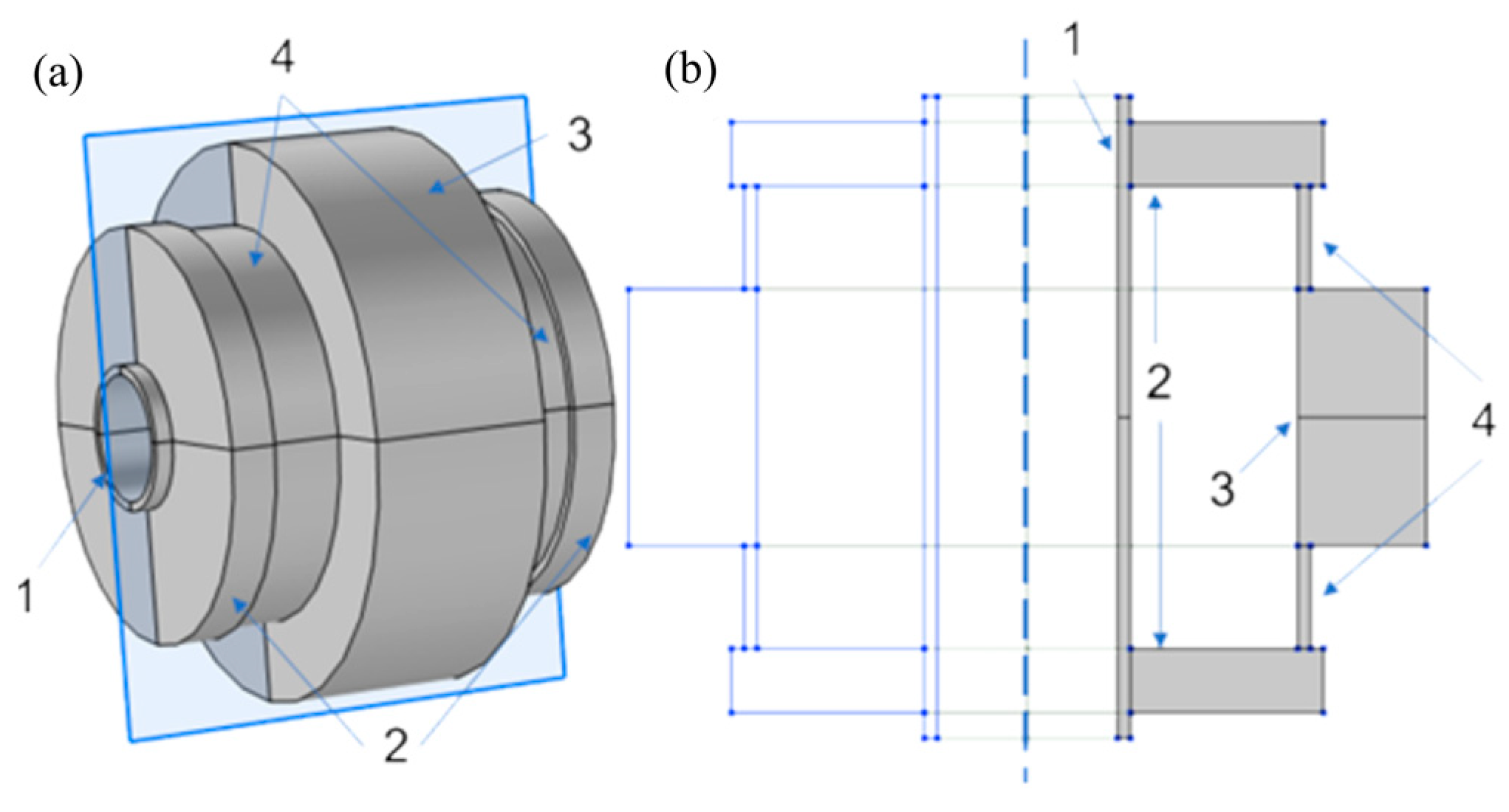
The overall length of the unit cell is 50 mm, with 1 mm wall thickness of the tube, 5 × 15 mm frame, 10 × 20 mm mass, and 1 × 9 mm membrane (
Figure 1). Considering that the Floquet boundary condition is applied to the tube’s ends, solving the eigenfrequency problem in the wavenumber domain in the range
, where
L—unit cell length, gives the set of frequencies for the given wavenumber and circumferential wavenumber
m = 0, 1, 2.
The mesh size can be defined by many criteria, for example, by defining the necessary among the points at the wavelength [
41]. For the model, the number of points is equal to 10, so the mesh size is 1 mm. The corresponding model is discretized by 418 quadratic elements in 4942 degrees of freedom. Computation on a Dell workstation took 7 min 15 s, which is relatively fast, but the increased complexity of the model (e.g., material anisotropy) increases the computational time. Potentially, the modification of the model, e.g., modified Drucker–Prager model [
42], can be implemented to enhance the accuracy and decrease the computation time.
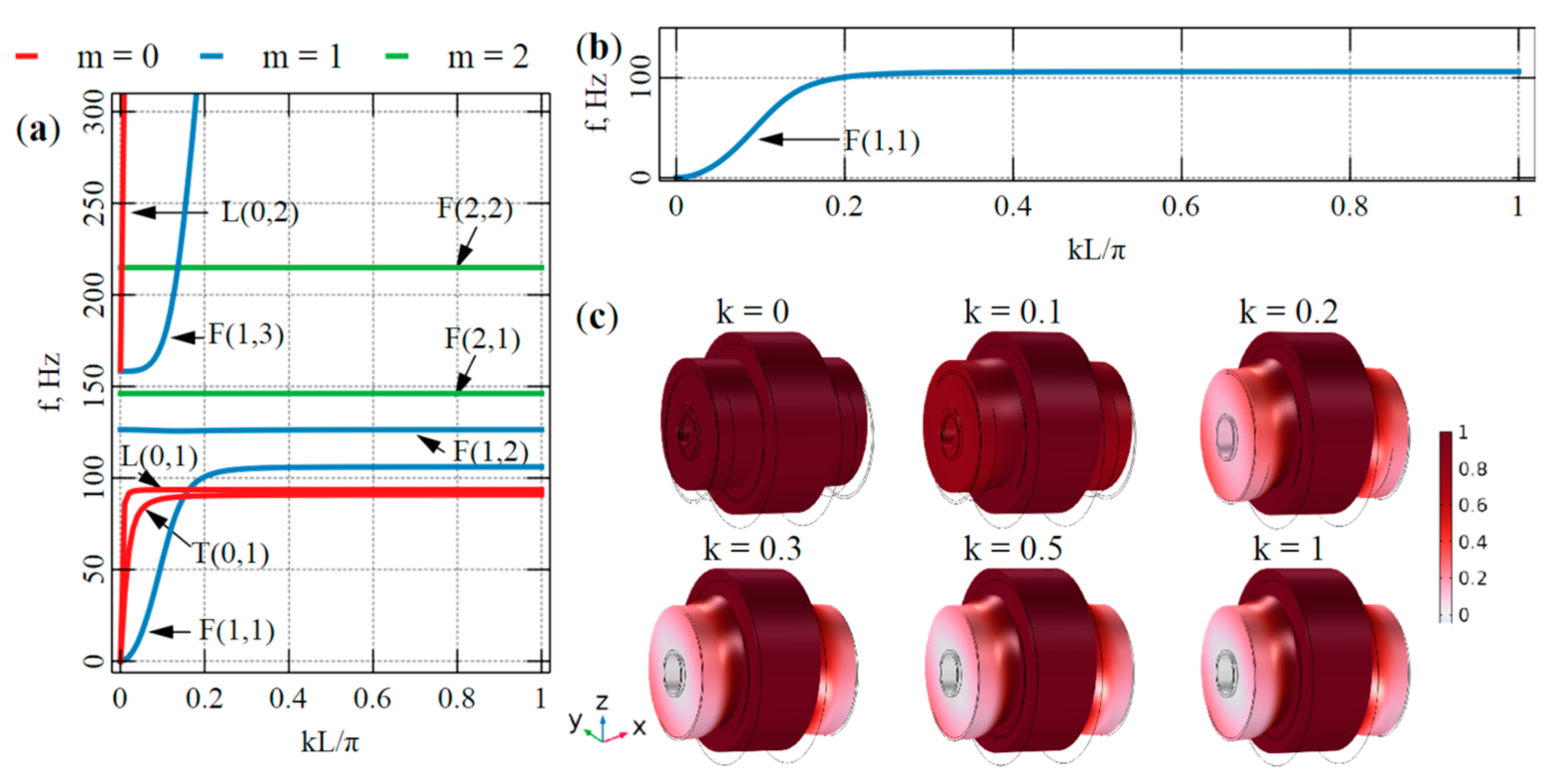
In
Figure 2a, the k–f dispersion curve is depicted. Firstly, multiple bandgaps can be observed, for example, between longitudinal guided wave modes L(0,1) and L(0,2), flexural waves F(1,1) and F(1,2), F(1,2) and F(1,3), or torsional wave T(0,1) and T(0,2) (exist higher than 300 Hz and not presented in graph), which makes the proposed resonator suitable for any vibration type. Also, it is interesting to note the curve behavior itself; all curves turn into a straight line, which means the mode shape transforms from the motion of the entire unit cell into the motion of the membrane resonator (
Figure 2b,c).
Since the flexural wave is dominant among all waves and the higher flexural waves (m > 1) represent the resonator’s motion, only the flexural wave with m = 1 is interesting. For this wave, bandgaps between F(1,1)–F(1,2) and F(1,2)–F(1,3) can be observed. As F(1,2) is a straight line, it can be excluded. Overall, the bandgap is 106 Hz to 158 Hz, where the first flexural wave does not exist.
The complete characterization of the dynamic impact of a deep-subwavelength object with linear internal vibrational degrees of freedom on a vibrational host body can be achieved by determining its effective mass. The effective mass is calculated based on the hybridization method [
43] to explain the resonator’s behavior. To define the effective mass
, Newton’s second law is employed Equations (5)–(7), expressed as follows:
where
—effective mass density,
V—unit cell volume,
F—force, a—acceleration,
—volume average,
S—boundary area,
—local stress, and
n—boundary unit normal vector. Since the flexural wave is interested, only the
Z component of the force and acceleration is considered.
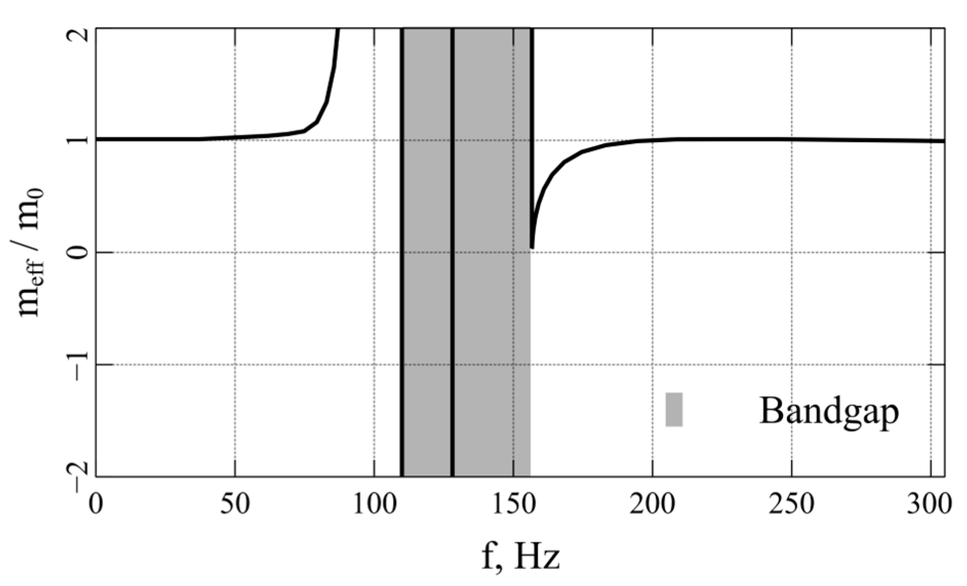
Figure 3 depicts a calculated relative effective mass (the total static mass of the unit cell is 77 g). It is seen that the closer the system is to the bandgap, the higher the effective mass of the unit cell, indicating a good vibration suppression effect to be expected. A straight line inside the bandgap is related to F(1,2) in
Figure 2a.
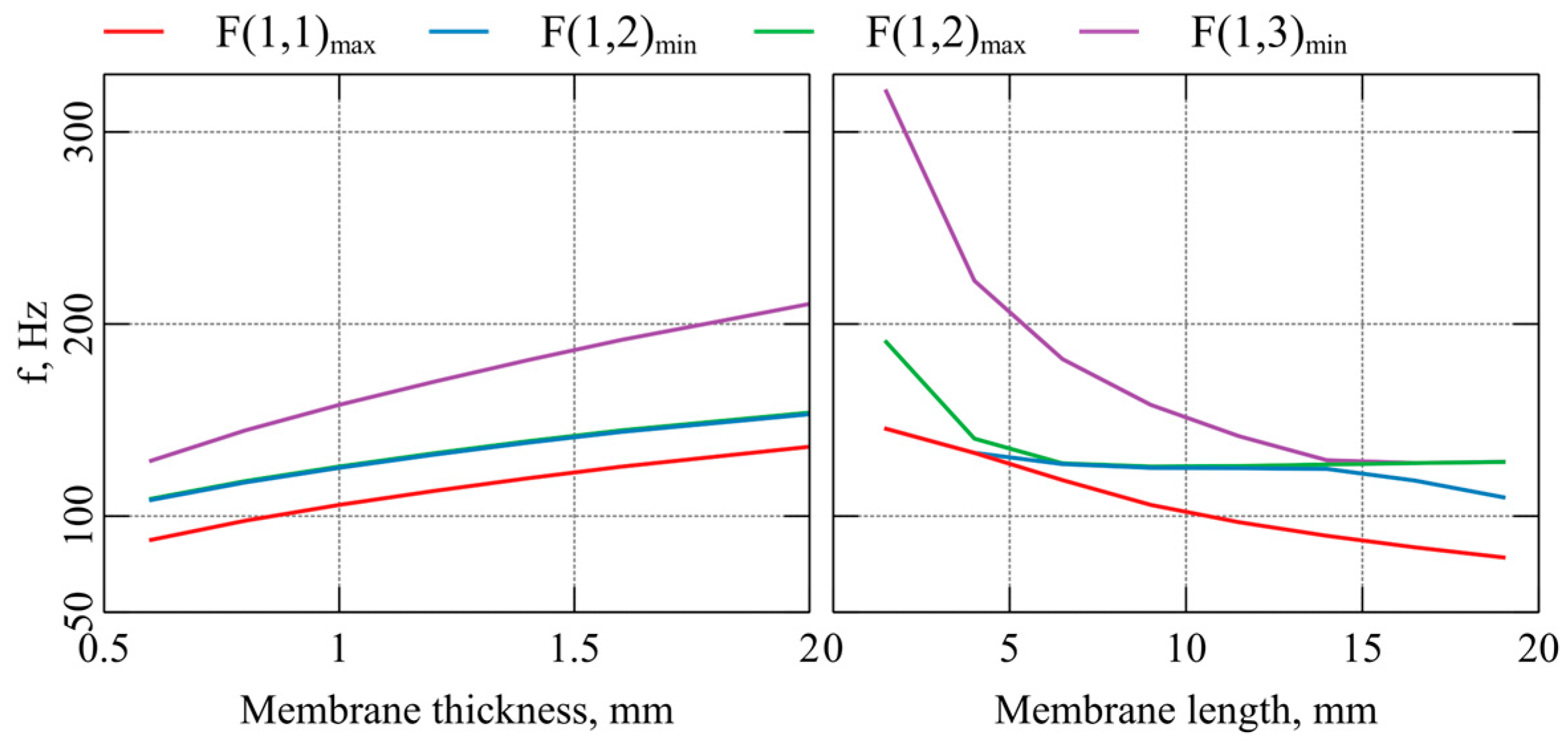
Before manufacturing the proposed resonator, it is interesting to analyze the bandgap frequencies’ sensitivity on the deviation of membrane geometry. For that, a parametric study was performed, with the membrane thickness varying from 0.5 mm to 2 mm and the membrane length varying from 1.5 mm to 19 mm. A closer look at
Figure 2a shows that four frequencies can be noted. It is the maximum frequency of the F(1,1), minimum and maximum frequency of the F(1,2) and minimum frequency of F(1,3). These frequencies form the bandgap and are depicted in
Figure 4. Firstly, the membrane thickness shifts the bandgap at higher frequencies and does not change the shape of the F(1,2). Secondly, the membrane length shows the opposite behavior; with the increased membrane length, the bandgap trends to lower-frequency forms between F(1,1) and F(1,2).
3. Experimental Setup
The proposed resonator (
Figure 5) was made by silicone (presented in
Table 1) and printed by a Sandraw (Taichung, Taiwan) silicone 3D printer with dimensions the same as in the previous section, except the internal diameter is slightly lower 16 mm (~15.6 mm). According to the manufacturer, the silicone 3D printed has a 0.4 mm resolution, so the bandgap should be at the predicted frequencies. The mass of the resonator is 56 g.
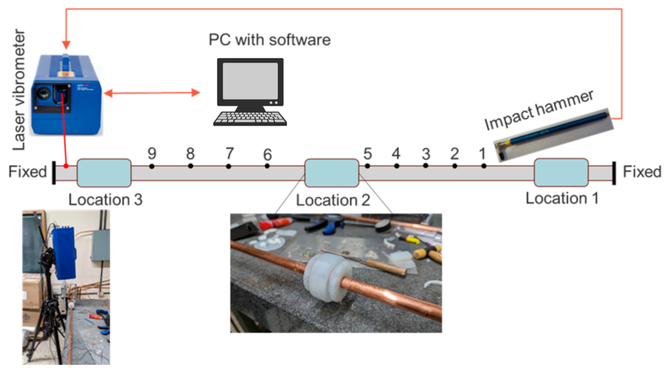
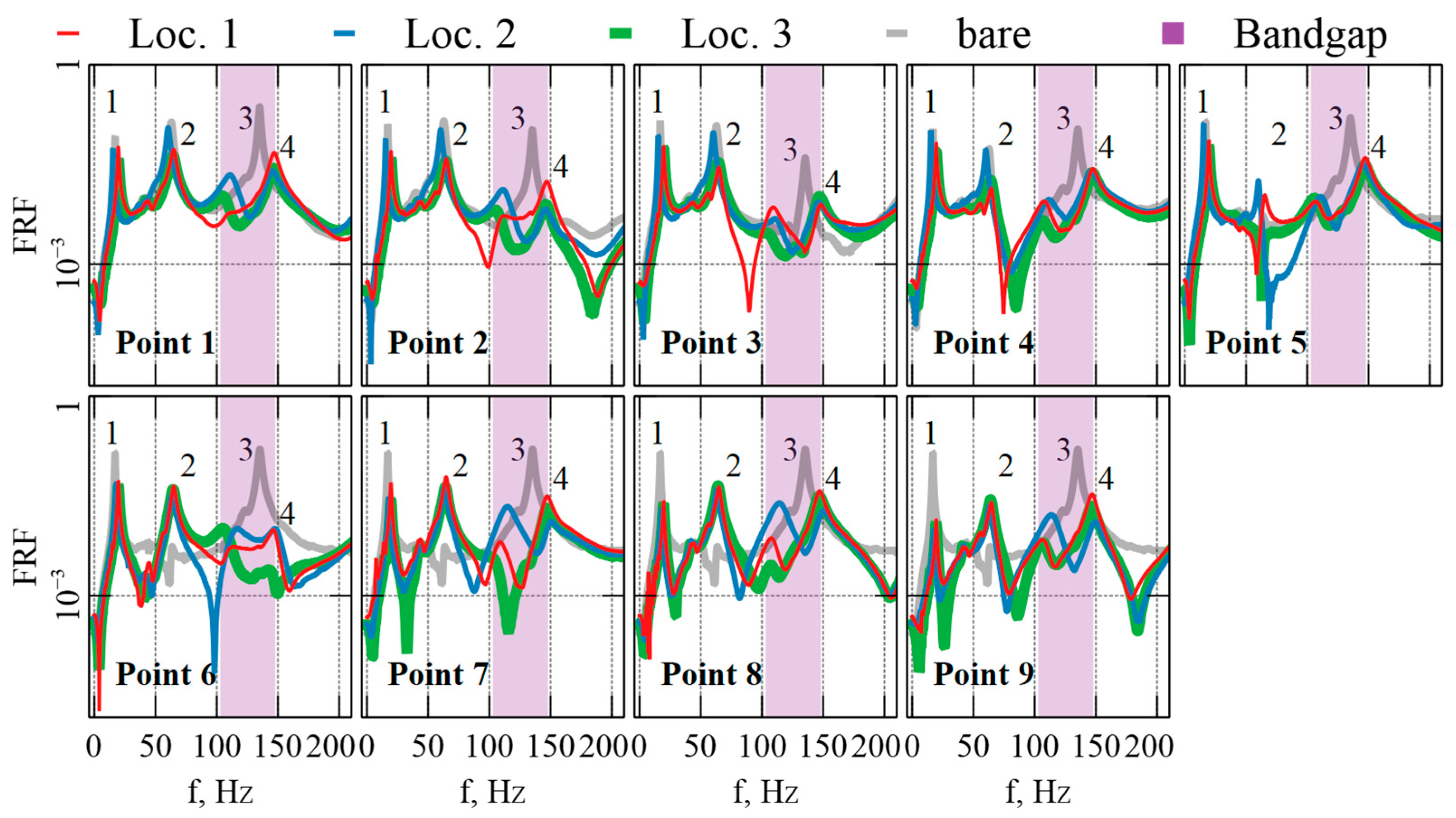
The copper tube with a 16 mm outer diameter, 1 mm wall thickness, and 1430 mm length was used as a host structure and clamped on an aluminum frame with silicone inserts on both ends. The tube lay on the aluminum frame with soft silicone inserts to minimize unnecessary external vibration. The resonator was attached to the tube without glue in three locations to avoid mode shape nodes. The roving hammer technique was used to accurately depict wave propagation in the tube with the resonator.
Figure 6 shows the scheme of the experimental setup. A PCB 084A17 impact hammer was used to excite the vibration of the tube with the resonator in nine different points with 100 mm spacing between points. The impact hammer connected to the Optomet (Darmstadt, Germany) laser doppler vibrometer and sent the trigger signal to start the measurement. The PC with the Optoscan ver. 2.15.5 software controls the entire process (start–stop measurement) and post-processes the measured data.
After triggering, the laser vibrometer measures the velocity amplitude for 16 s for better frequency resolution (example of measured data depicted in
Figure 7). After that, the raw measured signal is windowed by an exponential function.
A linear mechanical system with excitation
x(t) and response
y(t) signals can be characterized by the frequency response function (FRF) as in Equations (8)–(11):
where
X(f),
Y(f)—fast Fourier transform of the
x(t) and
y(t) respectively,
—average auto power spectrum and cross power spectrum, respectively,
—number of repetitions of excitation. The average values are used to make a spectrum less noisy, so each point was excited
times.
