Article

High-Precision Position Tracking Control with a Hysteresis Observer Based on the Bouc–Wen Model for Smart Material-Actuated Systems

1
92941 Troops, PLA, Huludao 125001, China
2
Changchun Institute of Optics, Fine Mechanics and Physics, Chinese Academy of Sciences, Changchun 130033, China
*
Author to whom correspondence should be addressed.
Actuators 2024, 13(3), 105; https://doi.org/10.3390/act13030105
Submission received: 4 February 2024 / Revised: 26 February 2024 / Accepted: 5 March 2024 / Published: 7 March 2024
(This article belongs to the Special Issue Advances in Smart Materials-Based Actuators)

Abstract

:
The Bouc–Wen model has been widely adopted to describe hysteresis nonlinearity in many smart material-actuated systems, such as piezoelectric actuators, shape memory alloy actuators, and magnetorheological dampers. For effective control design, it is of interest to estimate the hysteresis state that is not measurable. In this paper, the design of a state observer for the Bouc–Wen model is presented. It is shown that, with sufficiently high observer gains, the state estimate error, including that for the hysteresis state, converges to zero exponentially fast. The utility of the proposed hysteresis observer is illustrated in the design of a high precision output-feedback position tracking controller, and the resulting tracking error is shown to decay exponentially via Lyapunov analysis. Simulation and experimental results show that the proposed hysteresis observer and the high precision position tracking controller outperform a traditional extended state observer and the corresponding tracking controller, respectively.

1. Introduction

Hysteresis exists widely in smart material-actuated systems, such as shape memory alloy actuators [1], piezoelectric actuators [2], and magnetorheological dampers [3]. As an undesirable nonlinearity in general, hysteresis negatively impacts the performance of these systems. Mitigation of the hysteresis effect in smart materials has been an active research field in the past several decades and remains a subject of significant interest [4,5,6].
Modeling of the hysteresis is crucial to the proper design of controllers for systems with hysteresis. There are mainly two types of hysteresis models: physics-based models and phenomenological models. Examples of physics-based models include the Jiles–Atherton model [7] and the domain wall model [8], which are obtained by analyzing the physical relations between system variables. Phenomenological models can be classified into operator-based models and models based on differential equations. Operator-based models are often composed of the weighted superposition of a number (even continuum) of elementary hysteresis units, examples of which include the Prandtl–Ishlinskii model [9], Preisach model [10], and Krasnosel’skii–Pokrovkii model [11]. Notable differential equations-based models include the Duhem model [12,13], Backlash-like model [14], and Bouc–Wen model [15]. In addition, hysteresis of the smart material systems is not only related to the amplitude of the input, but also to the frequency of the input; it is defined as the rate-dependent property. To describe the rate-dependent hysteresis property, some rate-dependent hysteresis models are proposed. For example, [16] proposed a three-dimensional micromechanical model for describing the rate-dependent properties of piezoelectric materials. The rate-dependent Prandtl–Ishlinskii model [17] and Krasnosel’skii–Pokrovkii model [18] are also proposed to describe the rate-dependent hysteresis nonlinearity of various piezoelectric material actuators and have achieved a great rate-dependent hysteresis modeling effect of smart material systems. However, since the input to the hysteresis part of the Bouc–Wen model contains not only the positional information of the input values, but also the velocity information of the input values, it has certain rate-dependent properties. In particular, the Bouc–Wen model has the advantages of a simple structure, small numbers of parameters, and demonstrated efficacy in capturing hysteresis in smart material-actuated systems [19,20,21].
The Bouc–Wen model can be split into two parts; one is linear and the other is hysteretic. In most existing studies, the hysteresis term of the Bouc–Wen model is used to construct the feedforward compensation control for hysteresis nonlinearity in smart material-actuated systems [22]. In [23], an inverse compensation control scheme based on the Bouc–Wen model was proposed to mitigate the hysteresis of a piezoelectric actuator. In addition, a multiple-degree-of-freedom Bouc–Wen model (MDFBW) was presented in [24], where a multi-variable compensator with the inverse multiplicative structure of the MDFBW was designed to achieve tracking control for a three-degree-of-freedom piezo tube scanner. However, the feedforward compensation control technique is open-loop in nature, the performance of which is susceptible to the influence of external disturbances and model uncertainties. An alternative class of control approaches for the Bouc–Wen model treats the hysteresis part as an unknown disturbance and mitigates its effect via disturbance estimation and compensation. In [25], a proportional-integral-differentiation (PID)-sliding mode controller based on the simplified linear system was proposed to achieve high-precision tracking for piezo-nanopositioning stages; here, a high-gain observer was used to estimate position, velocity, and acceleration of the stage, and the hysteresis state was essentially treated as a perturbation in the velocity dynamics equation and computed based on the estimated acceleration, position, and velocity. In [26], an open-loop observer based on the Bouc–Wen model was proposed to estimate the hysteresis part for a piezoelectric nanopositioning stage. In [27], a disturbance observer and a fuzzy state observer were simultaneously designed to estimate unknown external disturbances and unmeasured states, respectively. However, these open-loop observers are just a copy of the Bouc–Wen model and are thus sensitive to the chosen initial estimate of the system state, which greatly limits the practical application of this kind of observer.
In this paper, we propose a novel state observer for the Bouc–Wen model. Different from existing state estimation methods, the hysteresis system is treated explicitly as a whole, instead of a linear system with a hysteresis perturbation. The hysteresis state is estimated without requiring knowledge of the initial state of the system, which significantly facilitates control implementation. The observer features a simple and efficient design. With Lyapunov analysis, we establish exponential convergence of the state observer for sufficiently high observer gains. To demonstrate its utility, the state observer is used to construct an output-feedback tracking controller, where exponentially fast-tracking performance is established via analysis. Finally, a simulation is conducted to illustrate the proposed hysteresis state observer and the aforementioned output-feedback position tracking controller. Both the simulation and experimental results show that the proposed approach outperforms the approach based on the traditional extended state observer, where the hysteretic part is treated as a disturbance.
The main contribution of this paper can be summarized as follows:
(1) The proposed high-gain hysteresis observer of the smart material is designed by using the Bouc–Wen model and the hysteresis part can be accurately estimated without the initial state of the smart material systems.
(2) The proposed high-gain hysteresis observer is beneficial to the controller design because all states of the whole system can be accurately estimated. And the stability of the whole output-feedback tracking controller with proposed high-gain hysteresis observer is proved by constructing the Lyapunov function. The proposed controller makes it easy to implement high-precision positioning control of the smart material systems.
The remainder of this paper is organized as follows. Section 2 reviews the Bouc–Wen model, followed by the design of the state observer along with its convergence analysis. In Section 3, the position tracking controller based on the state observer is proposed and its stability is established. Simulation and experimental results are presented in Section 4 and Section 5, respectively. Finally, the conclusion and future work are discussed in Section 6.

2. Observer Design for Bouc–Wen Models

2.1. Bouc–Wen Model

To describe the hysteresis nonlinearity of the smart material system, Bouc–Wen models are proposed and extended by Bouc and Wen [28,29]. A widely adopted form of the Bouc–Wen model is as follows:
m x ¨ + b x ˙ + k x = k ( d u h ) h ˙ = α 0 d u ˙ β u ˙ h γ u ˙ h ,
where x represents the system output (for example, displacement of a piezoelectric actuator), u is the input (input voltage of a piezoelectric actuator), and h is the hysteresis state. The variables m, b, and k represent the mass, the damping constant, and the stiffness, respectively, d is some proportional constant, and α 0 , β , and γ are the parameters of the hysteresis term. To facilitate the observer design, Equation (1) is rewritten as
x ˙ 1 = x 2 x ˙ 2 = a 1 x 1 a 2 x 2 a 1 x 3 + a 3 u x ˙ 3 = φ ( u ˙ , x 3 ) y = x 1 ,
where φ ( u ˙ , x 3 ) = α u ˙ β u ˙ x 3 γ u ˙ x 3 . Here, the constants a 1 , a 2 , a 3 , and α are related to those in Equation (1) via a 1 = k m , a 2 = b m , a 3 = k d m , and α = α 0 d , and y represents the output of the Bouc–Wen model. The variables x 1 , x 2 , and x 3 represent system states (which are the displacement, velocity, and hysteresis state, respectively). It is clear that the x 1 can be obtained using the displacement sensor, but x 2 and x 3 are not measurable directly. We next design a state observer to estimate the unknown states.

2.2. Design of the Hysteresis Observer

In this subsection, the proposed hysteresis observer design is presented, along with the convergence analysis. The observer takes the following form:
x ^ ˙ 1 = x ^ 2 + l 1 ( y x ^ 1 ) x ^ ˙ 2 = a 1 x ^ 1 a 2 x ^ 2 a 1 x ^ 3 + a 3 u + l 2 ( y x ^ 1 ) x ^ ˙ 3 = φ ( u ˙ , x ^ ) + l 3 ( y x ^ 1 ) ,
where x ^ i , i = 1 , 2 , 3 , are the estimate of state x i , and l 1 , l 2 , and l 3 are the observer gains, the conditions on which for estimate convergence are given in the following theorem.
Theorem 1.
Theorem: Consider the Bouc–Wen model Equation (2) and the proposed hysteresis observer Equation (3). Assume u ˙ to be bounded. Choose the observer gains such that
l 1 + a 2 > 0 ( l 1 + a 2 ) ( l 1 a 2 + a 1 + l 2 ) + l 3 a 1 > 0 l 3 a 1 < 0 .
Furthermore, the values of l 1 , l 2 , and l 3 are chosen to be large enough. Then the observer state x ^ will converge to the true state x exponentially fast.
Proof of Theorem 1.
Define the state observer errors, ε i = x ^ i x i , i = 1 , 2 , 3 , and ε = ( ε 1 , ε 2 , ε 3 ) T . It can be readily shown that ε satisfies
ε ˙ = A ε + B φ ˜ ( u ˙ , x 3 , x ^ 3 ) ,
where A = l 1 1 0 ( a 1 + l 2 ) a 2 a 1 l 3 0 0 , B = [ 0 , 0 , 1 ] T and φ ˜ ( u ˙ , x 3 , x ^ 3 ) = β u ˙ ( x 3 x ^ 3 ) + γ u ˙ ( x 3 x ^ 3 ) . It can be shown that, with (4), A will be Hurwitz. By noting ( | x ^ 3 | | x 3 | ) x ^ 3 x 3 = ε 3 , we have
φ ˜ ( u ˙ , x 3 , x ^ 3 ) ( β u ˙ + γ u ˙ ) ε 3 ( β + γ ) u ˙ ε = L ε ,
where L = ( β + γ ) ν ¯ and ν ¯ denote the bound on u ˙ . Now define a Lyapunov function
V o ( ε ) = ε T P ε ,
where P = P T > 0 is given by
P A + A T P = I .
The derivative of the Lyapunov Function (7) is given by
V ˙ o = ε T ε + 2 ε T P B φ ˜ ( u ˙ , x 3 , x ^ 3 ) .
With Equation (6), it can be shown that
ε T P B φ ˜ ( u ˙ , x 3 , x ^ 3 ) L P B ε 2 = L P ε 2 ,
where · denotes the 2-norm and induced-2-norm for vector and matrix, respectively. The latter leads to V ˙ o ( 1 2 L P ) ε T ε . □
Remark 1.
Since a 1 and a 2 are positive, the conditions for the observer gains specified in Theorem 1 can be easily satisfied. In particular, for a given l 3 < 0 , the first two inequalities in Equation (4) can be satisfied by choosing sufficiently large l 1 and l 2 .
Remark 2.
In the design process of the proposed state observer, we can choose sufficiently large l 1 , l 2 , and l 3 that P is made greater than 1 2 L . At this point, V ˙ o satisfies V ˙ o < 0 . According to the Lyapunov theory, it causes the state estimate error ε to converge to zero exponentially fast.

3. Position Tracking Controller

In this section, the proposed hysteresis state observer is exploited to develop a position tracking controller based on the output-feedback theory. Let x d denote the desired reference trajectory for x 1 that is twice continuously differentiable. Define the sliding surface function
σ = λ 1 e + e ˙ ,
where e = x 1 x d , e ˙ is the derivative of e with respect to the time, and λ 1 is a positive constant. Define e ^ = x ^ 1 x d , e ^ δ = x ^ 2 x ˙ d , and the controller is shown as
u = 1 a 3 [ x ¨ d + a 1 ( x ^ 1 + x ^ 3 ) + a 2 x ^ 2 λ 1 e ^ δ λ 2 ( λ 1 e ^ + e ^ δ ) ] ,
where λ 2 > 3 2 is a positive constant. We next show that the proposed controller will result in asymptotic tracking of the reference trajectory, namely, e 0 .
Consider a Lyapunov function
V 1 = 1 2 σ 2 .
The time-derivative of V 1 is calculated as
V ˙ 1 = σ σ ˙ ,
where σ ˙ is given by
σ ˙ = λ 1 e ˙ + e ¨ = λ 1 e ˙ + x ˙ 2 x ¨ d = λ 1 e ˙ a 1 x 1 a 2 x 2 a 1 x 3 + a 3 u x ¨ d .
With Equation (12), we obtain
σ ˙ = λ 1 e ˙ a 1 x 1 a 2 x 2 a 1 x 3 x ¨ d + x ¨ d + a 1 ( x ^ 1 + x ^ 3 ) + a 2 x ^ 2 λ 1 e ^ δ λ 2 ( λ 1 e ^ + e ^ δ ) = λ 1 ε 2 λ 2 ( λ 1 e ^ + e ^ δ ) + a 1 ( ε 1 + ε 3 ) + a 2 ε 2 = λ 1 ε 2 λ 2 σ λ 2 ( λ 1 ε 1 + ε 2 ) + a 1 ( ε 1 + ε 3 ) + a 2 ε 2 = λ 2 σ + ( λ 1 λ 2 + a 1 ) ε 1 ( λ 1 + λ 2 a 2 ) ε 2 + a 1 ε 3 ,
By substituting Equation (16) into Equation (14), we obtain
V ˙ 1 = σ [ λ 2 σ + ( λ 1 λ 2 + a 1 ) ε 1 ( λ 1 + λ 2 a 2 ) ε 2 + a 1 ε 3 ] = λ 2 σ 2 + ξ 1 σ ε 1 + ξ 2 σ ε 2 + ξ 3 σ ε 3 ,
where ξ 1 = a 1 λ 1 λ 2 , ξ 2 = a 2 λ 1 λ 2 , ξ 3 = a 1 . Because of ξ 1 σ ε 1 1 2 σ 2 + 1 2 ξ 1 2 ε 1 2 , ξ 2 σ ε 2 1 2 σ 2 + 1 2 ξ 2 2 ε 2 2 and ξ 3 σ ε 3 1 2 σ 2 + 1 2 ξ 3 2 ε 3 2 , we have
V ˙ 1 λ 2 σ 2 + 1 2 σ 2 + 1 2 ξ 1 2 ε 1 2 + 1 2 σ 2 + 1 2 ξ 2 2 ε 2 2 + 1 2 σ 2 + 1 2 ξ 3 2 ε 3 2 = ( λ 2 3 2 ) σ 2 + 1 2 ξ 1 2 ε 1 2 + 1 2 ξ 2 2 ε 2 2 + 1 2 ξ 3 2 ε 3 2 .
Because the state observer converges exponentially, we obtain
V ˙ 1 λ V 1 + Γ ( | | ε ( t 0 ) | | ) e κ ( t t 0 ) ,
where λ = 2 λ 2 3 > 0 , and Γ ( · ) is a class-K function, κ > 0 .
To prove that V 1 converges exponentially, we will use the following lemma [30].
Lemma 1.
If a function V : [ 0 , ) R satisfies V ˙ ( t ) μ V ( t ) + f ( t ) , for some constant μ and function f ( · ) , then the following is true:
V ( t ) e μ ( t t 0 ) V ( t 0 ) + t 0 t e μ ( t τ ) f ( τ ) d τ ,
for t t 0 .
Using Lemma 1 and Equation (19), we obtain
V 1 ( t ) e λ ( t t 0 ) V 1 ( t 0 ) + Γ ( | | ε ( t 0 ) | | ) t 0 t e λ ( t τ ) e κ ( τ t 0 ) d τ = e λ ( t t 0 ) V 1 ( t 0 ) + ζ ( | | ε ( t 0 ) | | ) λ κ ( e κ ( t t 0 ) e λ ( t t 0 ) ) .
From Equation (20), V 1 ( t ) converges to zero exponentially fast. This implies that σ 0 is exponentially fast, which in turn implies that the tracking error approaches zero exponentially fast.

4. Simulation Results

In this section, we verify the designed state observer and the output-feedback position tracking control method with simulation results. Experimental data from a commercial piezoelectric nanopositioning actuator is utilized to identify the parameters of the Bouc–Wen model adopted in the simulation: a 1 = 1.7168 × 10 8 , a 2 = 5743 , a 3 = 1.7808 × 10 9 , α = 4.6325 , β = 1.3567 , and γ = 0.4677 .

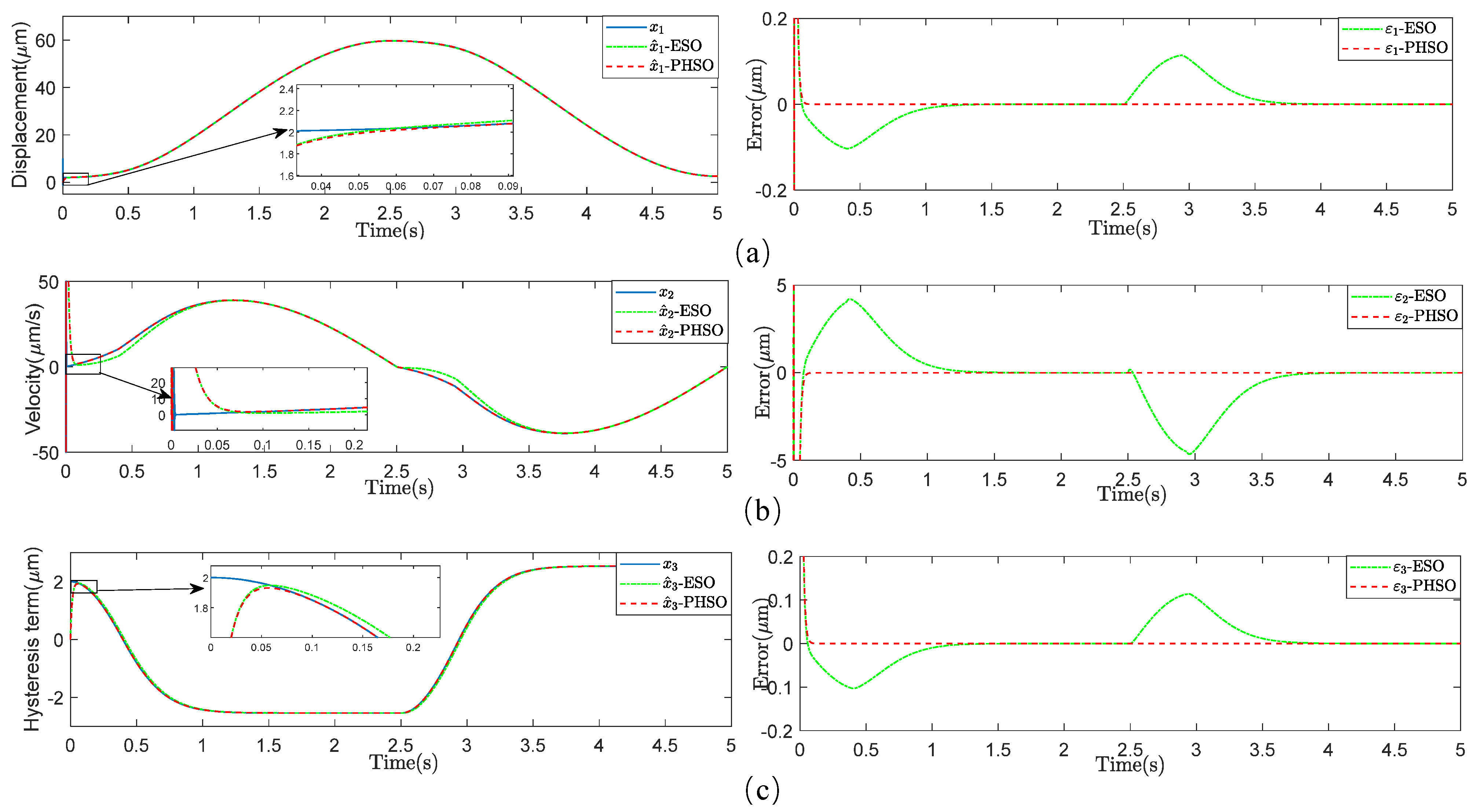
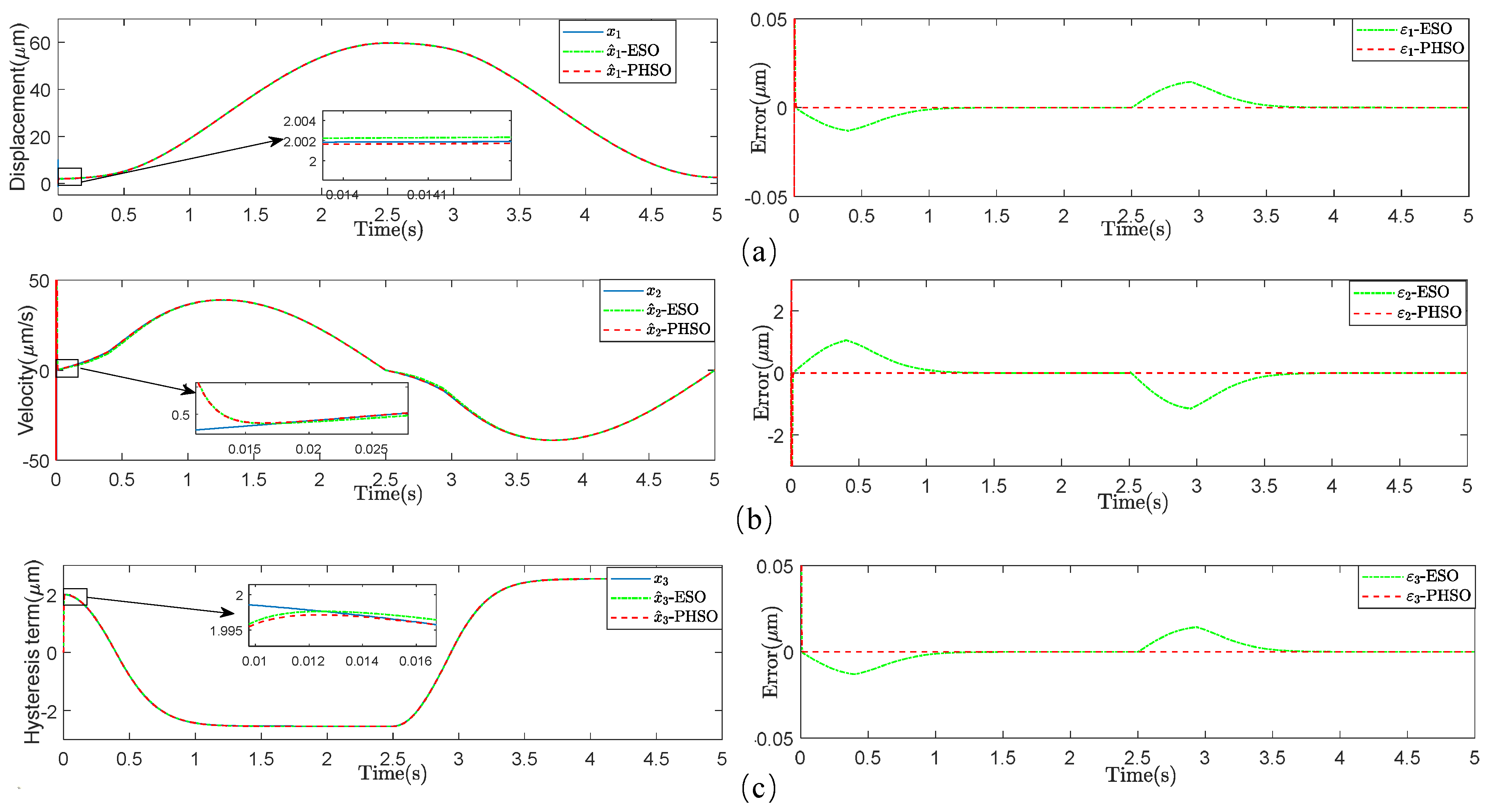
4.1. Hysteresis Observer Performance

To more thoroughly examine the performance of the proposed hysteresis state observer, we design a traditional extended state observer based on the Bouc–Wen model for comparison. The latter observer can be represented as
x ^ ˙ 1 = x ^ 2 + l 1 ( y x ^ 1 ) x ^ ˙ 2 = a 1 x ^ 1 a 2 x ^ 2 a 1 x ^ 3 + a 3 u + l 2 ( y x ^ 1 ) x ^ ˙ 3 = l 3 ( y x ^ 1 ) .
The first set of simulation results compares the performance in estimating the states. In the simulation, the Bouc–Wen model states are initialized as x 1 ( 0 ) = 10 , x 2 ( 0 ) = 2 , and x 3 ( 0 ) = 2 ; the initial states of the state observer are chosen as x ^ 1 ( 0 ) = 0 , x ^ 2 ( 0 ) = 0 , and x ^ 3 ( 0 ) = 0 . The reference input of the Bouc–Wen model is u = 3 sin ( 0.4 π t 0.5 π ) + 3 . The observer parameters l 1 , l 2 , l 3 are set to be 40, 40, and 80 . Figure 1 shows that the states of the system can be estimated by both observers, but the proposed hysteresis state observer outperforms the extended state observer. In particular, with the same set of observer gains, both observers show comparable rates of convergence to the steady-state values (within about 0.1 s); however, the estimation error from the proposed observer is significantly smaller. When the observer parameters l 1 , l 2 , l 3 are set to be 80, 160, and 640 , while all errors become smaller, Figure 2 shows that the proposed hysteresis state observer still clearly outperforms the extended state observer. In addition, the convergence of the proposed state observer is unrelated to the initial states of the piezoelectric nanopositioning system.

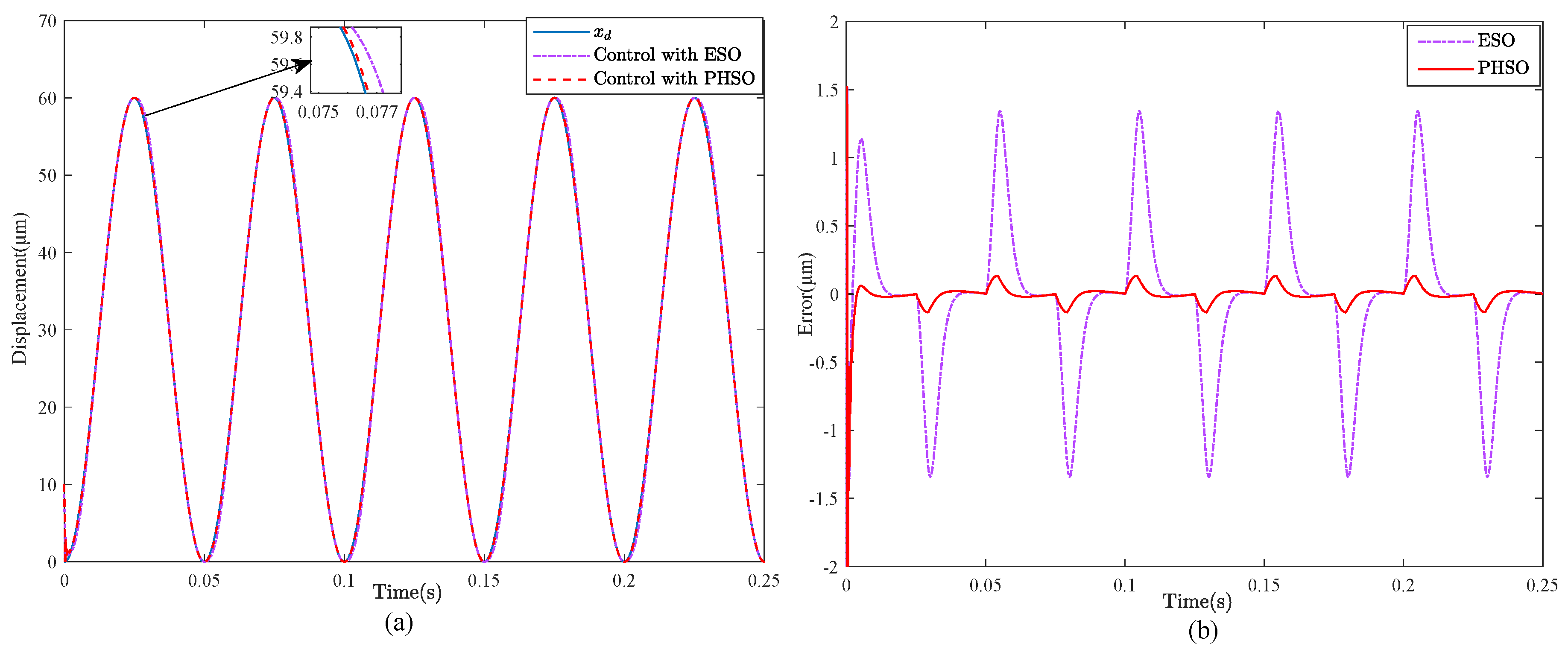
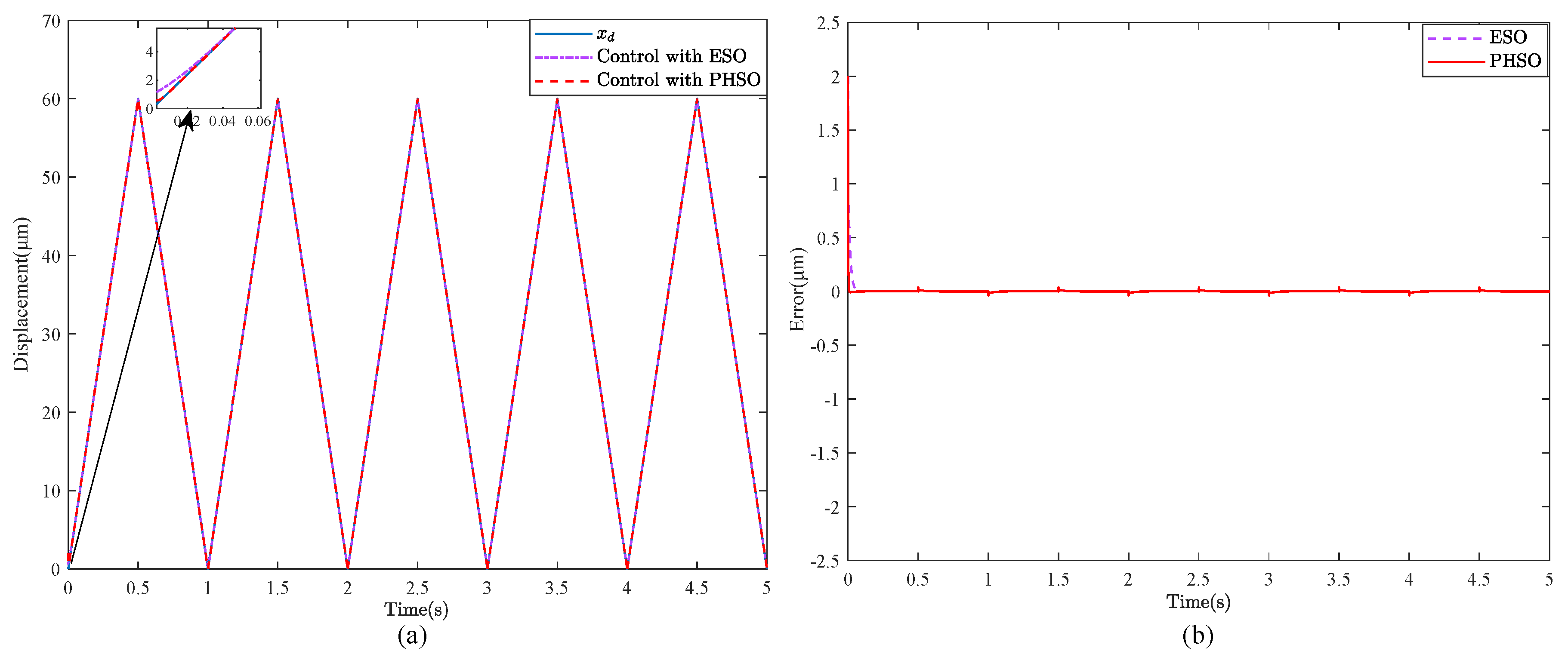
4.2. Output-Feedback Position Tracking Controller Performance

Based on the two state observers mentioned above, the performance of the output-feedback position tracking control method described in Section 3 is evaluated by a series of comparative simulation runs on tracking control, using the reference signal x d = 30 sin ( 2 π f t 0.5 π ) + 30 , with frequency f = 1 and 20 Hz, respectively. The parameters l 1 , l 2 , and l 3 for these two state observers are set as 80, 160, and 640 . The parameters for the output-feedback control method are chosen to be the same as λ 1 = 2.2 × 10 6 and λ 2 = 80 . Figure 3, Figure 4 and Figure 5 show the comparative simulation curves. In this paper, the performances of the controller are evaluated using the maximum error (MAXE), mean error (ME), and root means square error (RMSE), and the simulation results are further summarized in Table 1.
As can be seen in Figure 3, the proposed hysteresis state observer has smaller estimation errors compared with the extended state observer; in the meantime, the output of the system with the output-feedback position tracking controller based on the proposed hysteresis state observer rapidly tracks the desired signal at 1 Hz, and its MAXE is dropped by more than 0.2187 μ m compared to the case with the output-feedback controller based on the extended state observer. When the frequency of the reference signal is 20 Hz, it is noteworthy that the tracking error with the output-feedback position tracking control based on the proposed hysteresis state observer can still reach the steady state quickly as shown in Figure 4, where its MAXE at the steady state is 0.4043 μ m, which is reduced by 3.6194 μ m compared to the case with the extended state observer. From Table 1, the tracking error with the proposed observer is 80% or less than the error with the traditional observer. In addition, when the desired tracking trajectory is the triangular wave signal, the simulation results show that the ME of the piezoelectric nanoposition actuator with the proposed output-feedback controller based on PHSO is 0.0082 μ m, which is improved by 87.15% compared to that of the ESO method.

5. Experimental Results

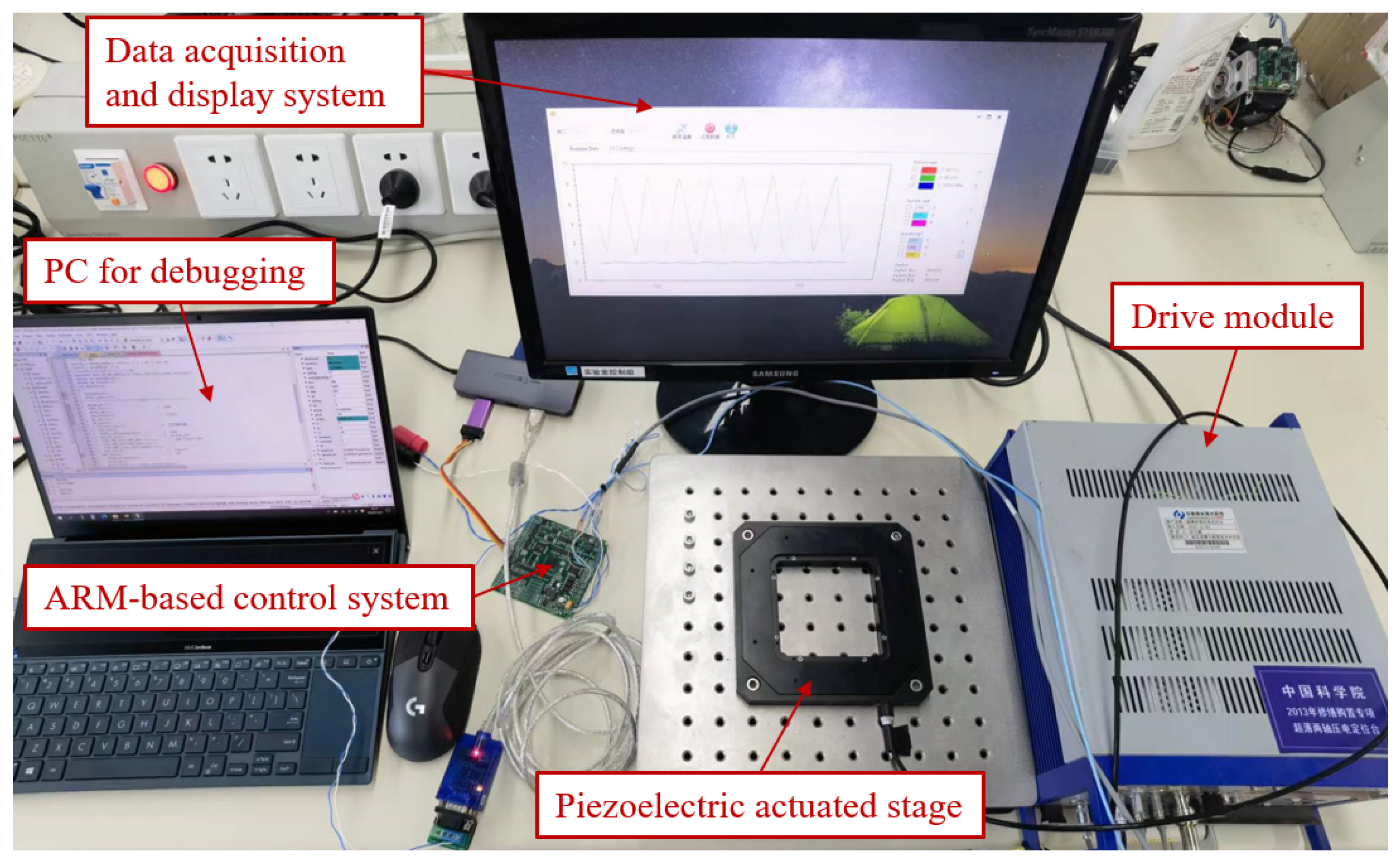
5.1. Experimental System and Parameters Setting

The experimental platform is developed based on an ARM-embedded system (its model number is STM32F407IGT6). A commercial piezoelectric-actuated XY-stage with the position travel of 200 μ m trip (P-542.2, PI, Germany) and a drive module (E-509.X3-503.00, PI, Germany) are used to finish the experiment. The connection relationship of all components in the experimental system is shown in Figure 6.
The parameters of the platform are identified as follows: a 1 = 159827.5 , a 2 = 713.8 , a 3 = 222665.02 , α = 0.4795 , β = 0.3762 , and γ = 0.0378 . The control algorithm is implemented in ARM, based on C language. The sampling time is set to 0.0002 s by balancing controller performance and ARM-embedded hardware processing power during the experiment. The parameters are tuned online using debug mode. The experimental data is sent to the data acquisition and display system via an RS422 serial port. The output-feedback position tracking control with ESO is selected as the comparison algorithm for the experiment. The parameters are set the same for both methods for a fair comparison. By trial and error, the observer parameters are set as l 1 = 8 , l 2 = 64 , l 3 = 512 , and the parameters of the feedback-output position tracking contoller are set as λ 1 = 1 and λ 2 = 2 .

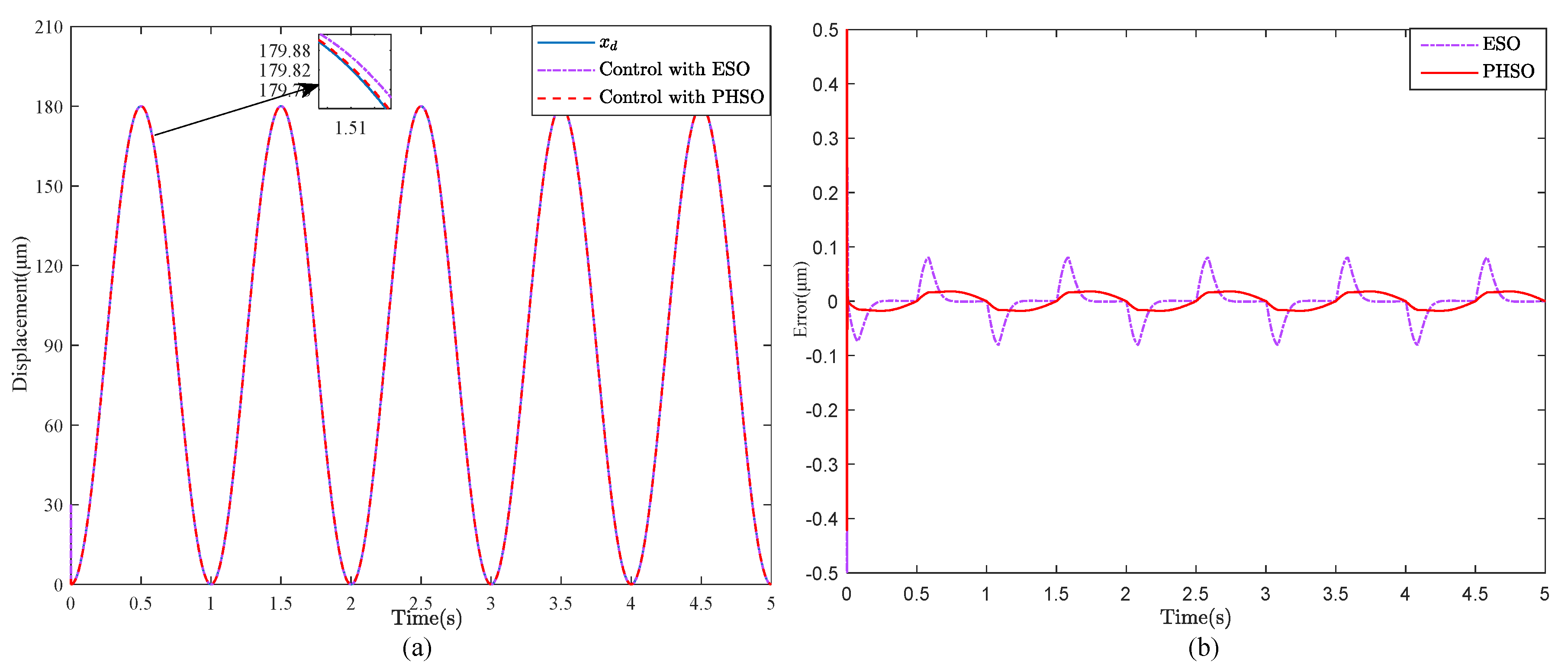
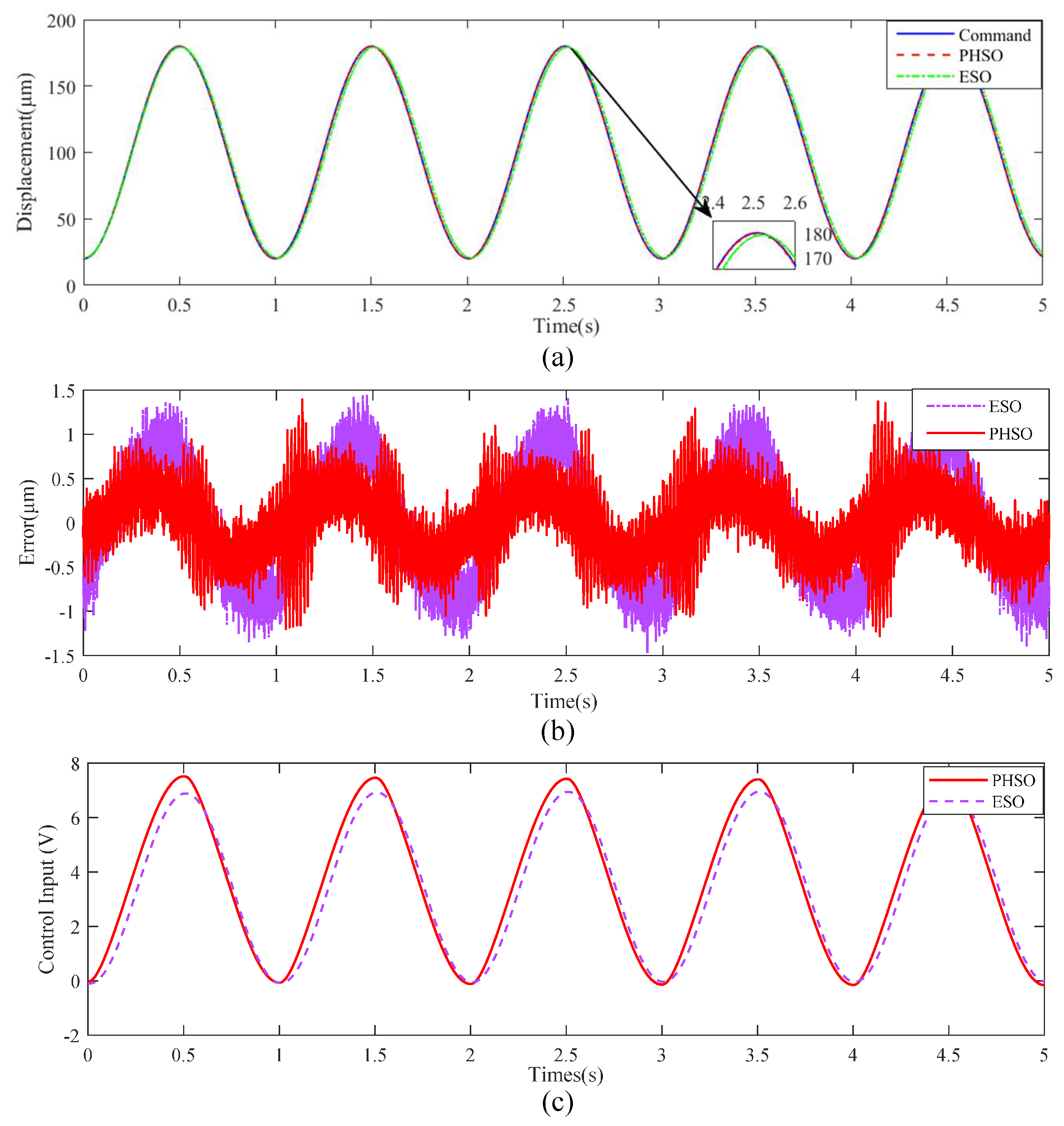
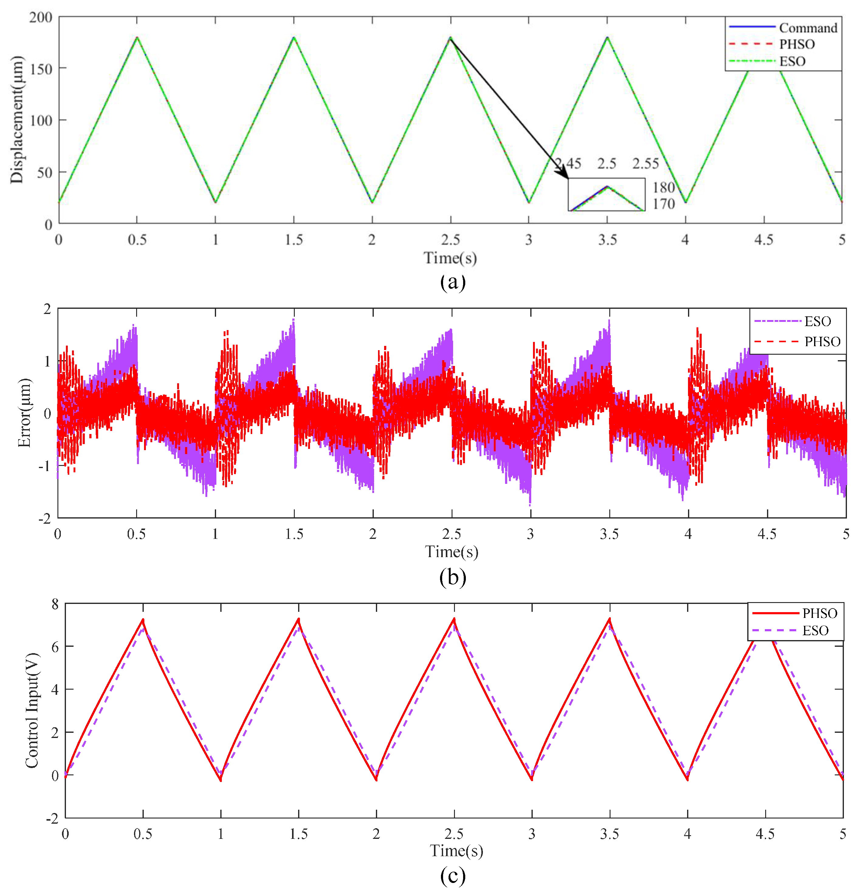
5.2. Proposed Position Tracking Controller Performance

To verify the superiority of the proposed algorithm, two common signals are selected for the reference signal: sinusoidal and triangular signals. The sinusoidal signal is set as (80sin(2 π t) + 100) μ m. The other signal is set as a triangular signal with a peak-to-peak value of 180 μ m, an offset of 100 μ m, and a period of 1 Hz. When the system signal tracking is in a steady state, the input and output response curves, control input curves, and error curves are shown in Figure 7 and Figure 8.
From the results, we can find that both methods can achieve signal tracking; however, the proposed method has higher tracking accuracy and less phase lag. This indicates that PHSO can achieve high-precision hysteresis observation. Specifically, to quantitatively compare the controller performance, MAXE, ME, and RMSE are used for evaluation and the results are shown in Table 2.
In addition, the applied control voltages based on two controllers to the piezoelectric-actuated stage are also shown in Figure 7c and Figure 8c. As shown in these figures, the control signals are smooth and do not exhibit chattering according to the performance indices described in [31].
The quantitative results show that the indicators of the proposed output-feedback position tracking controller with PHSO are improved comprehensively compared to the output-feedback position tracking controller with ESO. For a piezoelectric-actuated stage with a stroke of 200 μ m, the hysteresis effect is severe and the steady-state tracking errors under the proposed scheme are nearly half of those under a traditional extended state observer-based scheme.
It is noteworthy that the position tracking results do not display a complete match between simulations and experiments. In simulation, the tracking error using the PHSO method is significantly smaller than the one using the ESO method, which is improved by about 80%. However, the experiments show that there is not so much difference between the PHSO and ESO, which is improved by about 40%. This is because the external disturbances and model uncertainties have an impact on the performance of the controller. For example, the hysteresis part of PHSO based on the Bouc–Wen model cannot describe the actual hysteresis characteristics of the piezoelectric-actuated stage. However, the hysteresis part of PHSO method (that is replaced by the obtained Bouc–Wen model) is consistent with piezoelectric systems in simulation.

6. Conclusions

In this paper, we presented a simple and effective state observer to estimate the unmeasurable states of hysteresis systems represented by a Bouc–Wen model. Despite the nonlinear, non-smooth terms present in the Bouc–Wen model and the proposed hysteresis observer, we established exponential convergence of the hysteresis observer for sufficiently large observer gains. Simulation results showed that the state estimation errors converge to zero quickly, as predicted by the stability analysis. Based on the proposed hysteresis state observer, an output-feedback position tracking control method was proposed to mitigate the hysteresis effect in tracking control. The stability of the output-feedback position tracking control method with the hysteresis state observer was further established via Lyapunov analysis. The simulation showed that the steady-state tracking errors under the proposed scheme are 10% or less than the errors under a traditional extended state observer-based scheme. Furthermore, in the actual piezoelectric driven stage experimental system, the steady-state tracking errors under the proposed scheme are nearly 50% of the errors under a traditional extended state observer-based scheme.
For future work, we note that in this work the parameters of the Bouc–Wen model were assumed to be known. The extension of this work will look into the design and analysis of adaptive observers when the parameters are not known. In addition, we find that when the reference trajectory is a step signal, both ESO and HPSO methods have a “peak” phenomenon, which leads to the instability of the whole control system. In the future, we will study the “peak” phenomenon of the state observer and solve this problem.

Author Contributions

Conceptualization, J.Z.; methodology, J.Z. and Y.L.; validation, J.Z. and F.Z.; formal analysis: J.Z. and M.C.; writing—original draft preparation, J.Z. and Y.C.; writing—review and editing: Y.C. and R.X.; supervision and project administration, Y.L. All authors have read and agreed to the published version of the manuscript.

Funding

This paper is supported in part by the Program of Science and Technology Development Plan of Jilin Province of China under Grant No. 20220101118JC.

Data Availability Statement

The data presented in this study are available on request from the corresponding author.

Conflicts of Interest

The authors declare no conflicts of interest.

References

  1. Jin, M.; Jinoh, L.; Kyung, K.A. Continuous nonsingular terminal sliding-mode control of shape memory alloy actuators using time delay estimation. IEEE/ASME Trans. Mech. 2015, 20, 899–909. [Google Scholar] [CrossRef]
  2. Zhang, C.; Zhou, M.; Nie, L.; Zhang, X.; Su, C.Y. Prandtl-Ishlinskii model based event-triggered prescribed control: Design and application to piezoelectric-driven micropositioning stage. Mech. Syst. Signal. Process. 2023, 200, 110562. [Google Scholar] [CrossRef]
  3. Tan, X.; John, S.B. Modeling and control of hysteresis in magnetostrictive actuators. Automatica 2004, 40, 1469–1480. [Google Scholar] [CrossRef]
  4. Mohammad, A.; Rakotondrabe, M.; Al-Darabsah, I.; Aljanaideh, O. Internal model-based feedback control design for inversion-free feedforward rate-dependent hysteresis compensation of piezoelectric cantilever actuator. Control Eng. Pract. 2018, 72, 29–41. [Google Scholar]
  5. Nie, L.; Zhou, M.; Cao, W.; Huang, X. Improved Nonlinear Extended Observer Based Adaptive Fuzzy Output Feedback Control for a Class of Uncertain Nonlinear Systems with Unknown Input Hysteresis. IEEE Trans. Fuzzy Syst. 2023, 31, 3679–3689. [Google Scholar] [CrossRef]
  6. Xu, R.; Tian, D.; Wang, Z. Adaptive Disturbance Observer-Based Local Fixed-Time Sliding Mode Control with an Improved Approach Law for Motion Tracking of Piezo-Driven Microscanning Systems. IEEE Trans. Ind. Electron. 2024. early access. [Google Scholar] [CrossRef]
  7. Rosenbaum, S.; Ruderman, M.; Strohla, T.; Bertram, T. Use of Jiles-Atherton and Preisach hysteresis models for inverse feed-forward control. IEEE Trans. Magn. 2010, 46, 3984–3989. [Google Scholar] [CrossRef]
  8. Smith, R.; Ounaie, Z. A domain wall model for hysteresis in piezoelectric materials. J. Intell. Mater. Syst. Struct. 2000, 11, 62–79. [Google Scholar] [CrossRef]
  9. Edardar, M.; Tan, X.; Khalil, H.K. Design and analysis of sliding mode controller under approximate hysteresis compensation. IEEE Trans. Control Syst. Technol. 2015, 23, 598–608. [Google Scholar] [CrossRef]
  10. Li, Z.; Zhang, X.; Su, C.Y.; Chai, T. Nonlinear control of systems preceded by Preisach hysteresis description: A prescribed adaptive control approach. IEEE Trans. Control Syst. Technol. 2016, 24, 451–460. [Google Scholar] [CrossRef]
  11. Li, Z.; Shan, J.; Gabbert, U. Inverse compensation of hysteresis using Krasnoselskii-Pokrovskii model. IEEE/ASME Trans. Mech. 2018, 23, 966–971. [Google Scholar] [CrossRef]
  12. Xu, R.; Wang, Z.; Zhou, M.; Tian, D. A robust fractional-order sliding mode control technique for piezoelectric nanopositioning stages in trajectory-tracking applications. Sens. Actuators A 2023, 363, 114711. [Google Scholar] [CrossRef]
  13. Wang, X.; Alici, G.; Tan, X. Modeling and inverse feedforward control for conducting polymer actuator with hysteresis. Smart Mater. Struct. 2014, 23, 025015. [Google Scholar] [CrossRef]
  14. Ibrir, S.; Su, C.Y. Adaptive stabilization of a class of feedforward nonlinear systems subject to unknown backlash-hysteresis inputs. IEEE Trans. Control Syst. Technol. 2017, 25, 1180–1192. [Google Scholar] [CrossRef]
  15. Rakotondrabe, M. Bouc-Wen modeling and inverse multiplicative structure to compensate hysteresis nonlinearity in piezoelectric actuators. IEEE Trans. Autom. Sci. Eng. 2011, 8, 428–431. [Google Scholar] [CrossRef]
  16. Delibas, B.; Arockiarajan, A.; Seemann, W. Rate dependent properties of perovskite type tetragonal piezoelectric materials using micromechanical model. Int. J. Solids Struct. 2006, 43, 697–712. [Google Scholar] [CrossRef]
  17. Yang, M.; Li, C.; Gu, G.; Zhu, L. Modeling and compensating the dynamic hysteresis of piezoelectric actuators via a modified rate-dependent Prandtl–Ishlinskii model. Smart Mater. Struct. 2015, 24, 125006. [Google Scholar] [CrossRef]
  18. Xu, R.; Tian, D.; Zhou, M. A rate-dependent KP modeling and direct compensation control technique for hysteresis in piezo-nanopositioning stages. J. Intell. Mater. Syst. Struct. 2022, 33, 629–640. [Google Scholar] [CrossRef]
  19. Zhu, W.; Rui, X. Hysteresis modeling and displacement control of piezoelectric actuators with the frequency-dependent behavior using a generalized Bouc-Wen model. Precis. Eng. 2016, 43, 299–307. [Google Scholar] [CrossRef]
  20. Ramli, M.; Minh, T.; Chen, X. Pseudoextended Bouc-Wen model and adaptive control design with applications to smart actuators. IEEE Trans. Control Syst. Technol. 2019, 27, 2100–2109. [Google Scholar] [CrossRef]
  21. Wang, Z.; Xu, R.; Wang, L.; Tian, D. Finite-time adaptive sliding mode control for high-precision tracking of piezo-actuated stages. ISA Trans. 2022, 129, 436–445. [Google Scholar] [CrossRef] [PubMed]
  22. Yu, S.; Feng, Y.; Yang, X. Extended state observer–based fractional order sliding-mode control of piezoelectric actuators. J. Syst. Control Eng. 2021, 235, 39–51. [Google Scholar] [CrossRef]
  23. Wang, Z.; Zhang, Z.; Mao, J. Precision tracking control of piezoelectric actuator based on Bouc-Wen hysteresis compensator. Electron. Lett. 2012, 48, 1459–1460. [Google Scholar] [CrossRef]
  24. Habineza, D.; Rakotondrabe, M.; Gorrec, Y. Bouc-Wen modeling and feedforward control of multivariable hysteresis in piezoelectric systems: Application to a 3-dof piezotube scanner. IEEE Trans. Control Syst. Technol. 2015, 23, 1797–1806. [Google Scholar] [CrossRef]
  25. Li, Y.; Xu, Q. Adaptive sliding mode control with perturbation estimation and PID sliding surface for motion tracking of a piezo-driven micromanipulator. IEEE Trans. Control Syst. Technol. 2010, 18, 798–810. [Google Scholar] [CrossRef]
  26. Sofla, M.; Rezaei, S.; Areinejad, Z.; Saadat, M. Hysteresis-observer based robust tracking control of piezoelectric actuators. Am. Control Conf. 2010, 1, 4187–4192. [Google Scholar]
  27. Wu, Y.; Ma, H.; Chen, M.; Li, H. Observer-based fixed-time adaptive fuzzy bipartite containment control for multiagent systems with unknown hysteresis. IEEE Trans. Fuzzy Syst. 2022, 30, 1302–1312. [Google Scholar] [CrossRef]
  28. Bouc, R. Forced vibration of mechanical systems with hysteresis. In Proceedings of the Fourth Conference on Nonlinear Oscillations, Prague, Czech Republic, 5–9 September 1967; p. 315. [Google Scholar]
  29. Wen, Y. Method for random vibration of hysteretic systems. J. Eng. Mech. Div. 1976, 102, 249–263. [Google Scholar] [CrossRef]
  30. Ioannou, P.; Sun, J. Robust Adaptive Control; CRC Press: Boca Raton, FL, USA, 1996; p. 75. [Google Scholar]
  31. Izadbakhsh, A.; Kheirkhahan, P. Nonlinear PID control of electrical flexible joint robots-Theory and experimental verification. In Proceedings of the 2018 IEEE International Conference on Industrial Technology (ICIT), Lyon, France, 19–22 February 2018; pp. 250–255. [Google Scholar]
Figure 1. Estimation of the states based on the extended state observer (ESO) and the proposed hysteresis state observer (PHSO) with l 1 = 40 , l 2 = 40 , l 3 = 80 . (a) Estimated states x 1 . (b) Estimated states x 2 . (c) Estimated states x 3 .
Actuators 13 00105 g001
Figure 2. Estimation of the states based on the ESO and the PHSO with l 1 = 80 , l 2 = 160 , l 3 = 640 . (a) Estimated states x 1 . (b) Estimated states x 2 . (c) Estimated states x 3 .
Actuators 13 00105 g002
Figure 3. Simulation results of the output-feedback position tracking control method with the ESO and the PHSO when tracking a sinusoidal trajectory at 1 Hz. (a) Desired and achieved output trajectories. (b) Tracking error.
Actuators 13 00105 g003
Figure 4. Simulation results of the output-feedback position tracking control method with the ESO and the PHSO when tracking a sinusoidal trajectory at 1 Hz. (a) Desired and achieved output trajectories. (b) Tracking error.
Actuators 13 00105 g004
Figure 5. Simulation results of the output-feedback position tracking control method with the ESO and the PHSO when tracking a triangular wave trajectory. (a) desired and achieved output trajectories. (b) tracking error.
Actuators 13 00105 g005
Figure 6. Experimental system.
Actuators 13 00105 g006
Figure 7. Experimental results of the output-feedback position tracking control with the PHSO and ESO when tracking a sinusoidal trajectory at 1 Hz. (a) Tracking trajectory. (b) Tracking error. (c) Control Input.
Actuators 13 00105 g007
Figure 8. Experimental results of the output-feedback position tracking control with the PHSO and ESO when tracking a triangle trajectory at 1 Hz. (a) Tracking trajectory. (b) Tracking error. (c) Control input.
Actuators 13 00105 g008
Table 1. Comparative simulation results under different frequencies of desired signal.
Frequency Criteria Controller with ESO Controller with PHSO Improved
MAXE ( μ m)0.24060.021990.89%
1 Hz (sine)ME ( μ m)0.05160.005389.73%
RMSE ( μ m)0.20780.009895.28%
MAXE ( μ m)4.02370.404389.95%
20 Hz (sine)ME ( μ m)1.03130.105189.81%
RMSE ( μ m)2.04510.155492.40%
MAXE ( μ m)3.10320.063997.94%
triangularME ( μ m)0.06230.008287.15%
RMSE ( μ m)0.24310.014594.24%
Table 2. Comparative results under different desired signal.
Signal Criteria Controller with ESO Controller with PHSO Improved
MAXE ( μ m)1.56191.396010.62%
SineME ( μ m)0.59150.317846.27%
RMSE ( μ m)0.66460.380442.76%
MAXE ( μ m)1.79831.65937.73%
TriangleME ( μ m)0.52860.297643.70%
RMSE ( μ m)0.65830.376442.82%
Disclaimer/Publisher’s Note: The statements, opinions and data contained in all publications are solely those of the individual author(s) and contributor(s) and not of MDPI and/or the editor(s). MDPI and/or the editor(s) disclaim responsibility for any injury to people or property resulting from any ideas, methods, instructions or products referred to in the content.

