Abstract
Aiming to address problems such as low sampling success rate and long computation time in the motion planning of a dual-arm cooperative system with multiple constraints, this paper proposes an Informed-Bi-Quick RRT* algorithm based on offline sampling. First, in the process of pre-sampling, the new algorithm relaxes the approximation of constrained manifolds by introducing the idea of incremental construction, and it incorporates the stochastic gradient descent method to replace global random sampling with local random sampling, which enriches the data set and shortens the offline sampling time of the data set. Second, the new algorithm improves the original Quick-RRT* algorithm by combining the two-tree idea and the multi-target bias expansion strategy, and it improves the adaptability of the algorithm to different obstacle environments. In addition, the loosely constrained motion and tightly constrained motion in the two-arm cooperative system are analyzed, and the adaptive planning of the two-arm trajectory in different motions is described in detail. In this paper, the two-arm cooperative model constructed with UR5 and UR10 robot arms is studied, and the ability of the proposed algorithm to deal with multiple constraints is verified by simulating assembly and handling tasks. The experimental results show that compared with other methods, the proposed algorithm has obvious advantages in path quality and planning efficiency.
1. Introduction
The basis of the coordinated motion realization system is to perform reasonable motion planning according to the operation scene [1,2]. With the continuous expansion of the application scenarios of the two-armed cooperative system, increasing numbers of task constraints are faced, such as end-effector constraints, closed-loop constraints, and geometric constraints [3]. Planning complex cooperative systems is an important and specific problem when many constraints need to be considered in special cases. At present, the mainstream motion-planning methods [4,5] that deal with a single constraint are relatively common and effective, but many algorithms have certain limitations in the face of dealing with multiple constraints [6,7,8,9]. For example, methods based on Inverse Kinematics (IK) [10] are traditional methods for dealing with end-effector constraints of redundant robotic arms that can directly evaluate constraints and sample target poses. In the face of multiple end-effector constraints, the IK-based response control method [11,12] relaxes the hard geometric constraints to soft ones based on cost through nonlinear optimization. Under operator supervision, this optimization is feasible. Optimizer-based programming methods [13,14] are effective for everyday operational tasks, adding kinematic constraints to the optimizer to generate a trajectory that follows a given path. Long et al. [15] formed a constrained operable polyhedron that help generate trajectories in optimization-based motion planners. However, these two types of algorithms share the same problem of being easily trapped in local minima and having difficulty dealing with complex paths with multiple constraints [16,17].
Sampling-based planning methods [18,19,20,21,22] are preferred for solving obstacle constraints in high-dimensional configuration spaces due to their adaptability. However, when faced with multiple task constraints, sampling planning can present challenges. The main difficulty arises from the requirement that the configuration satisfies the constraint function, which defines the manifold in the configuration space. Sampling-based motionplanning algorithms often struggle to uniformly sample the configuration space and obtain constrained configurations.
The planning methods based on multi-constraint sampling include projection, continuous, and offline sampling [23]. The projection-based method finds the configuration that satisfies the constrained function by solving the system of constrained equations. The projection operator then obtains the configuration and maps it to the implicit manifold. This method was first used by Yakey et al. [24] for the closed-loop control of a parallel manipulator. The authors apply the projection idea to general end-effector constraints and optimize the projection process using stochastic gradient descent and Jacobian gradient descent. For instance, Berenson et al. [25] combine the Jacobian matrix projection method with C-space sampling to move the sample onto the constrained manifold and solve the motion-planning problem in high-dimensional space with end-effector attitude and joint torque constraints. Recently implemented planners can solve complex combinations of constraints using projections with general constraints. For example, humanoid path planner (HPP) [26,27] systems combine explicit and implicit manifold constraints into more efficient projections. Projection enforces strict adherence to the constraints, but it can result in a lack of available information, and the iterative projection process consumes significant computational resources, leading to unacceptably long computation times.
The continuation-based method generates the tangential space of an implicit manifold from a known target configuration. By applying the projection to a configuration sampled within the tangential space, an efficient local motion can be generated. The tangent spaces are grouped together to create piecewise linear approximations or continuations of the manifold, resulting in a new configuration close to the target manifold [28]. The study utilized early manipulators constrained by general end-effectors [29] and redundant manipulators constrained by curve tracking [30]. To compute the solution of a constrained manifold, some methods [31,32] combined with numerical continuation techniques define the atlas as a piecewise linear approximation of a constrained manifold in the tangent space. This is achieved by gradually building an atlas interleaved with the space, allowing planners to explore or reuse the results of previous runs online. However, linear approximation, or continuation, also has clear disadvantages. In addition to the expensive calculation of the matrix, when the manifold becomes highly curved, the tangential motion quickly deviates from the surface of the manifold, and the tangential space will not be reasonable.
In general, the above two algorithms can only be designed for or applied to relatively simple problems or specific robot arm structures, and it is difficult to provide general solutions for general motion-planning problems.
Therefore, this paper proposes an optimized off-line sampling-based motion-planning method for multi-constrained dual-arm cooperative systems. The offline sampling-based approach [33,34,35] is a configuration that precomputes a set of constraints and then uses this set for sampling and local planning. At its core, it is possible to construct an approximation of a constrained manifold offline and then use this approximation to plan directly on the constrained manifold rather than in the entire configuration space. The advantage is that constrained manifolds can be quickly sampled online using data structures computed offline, rather than using relatively slow dedicated sampling algorithms to sample the configuration space. To address the issues of low sampling success rate and the slow generation speed of offline data sets, this paper proposes the idea of relaxing constraints during the sample set generation process. The paper establishes constraint tolerances and task errors, and controllably relaxes the range of constrained manifold approximation. This approach increases the number of possible pre-sampling configurations, resulting in an improved success rate of subsequent sampling. Secondly, local random sampling is used instead of pure random sampling. Additionally, a random gradient descent method is employed to prioritize the presence of a matching new configuration within a certain range of collected target configurations. This helps to shorten the construction time of the sample data set. In addition, this paper enhances the original Quick-RRT* algorithm by combining the two-tree concept and multi-objective biasing expansion strategy. This optimization improves the initial path and accelerates the convergence speed while ensuring asymptotic optimization. Additionally, it enhances the algorithm’s adaptability to different obstacle environments. Finally, this paper analyzes the difference in task constraints in loosely constrained motion and tightly constrained motion (taking assembly and handling as examples, respectively) under collaborative tasks, and describes the influence of different task constraints on the motion planning of both arms in detail. In addition, under master–slave control, the optimized planning method based on advance sampling is used to realize the assembly and handling of dual robot arms.
The structure of this thesis is as follows: The second section introduces a review of work related to constrained motion planning; the third section describes, in detail, how to optimize the motion-planning method based on offline sampling; the fourth section analyzes the task constraints present in collaborative systems, and the fifth section presents various experimental results and discusses our approach and other previous work. The sixth section contains the conclusion.
2. Method
2.1. Problem Description
Since the constraints of the end pose of the manipulator and the obstacles in the environment are treated as separate entities during the motion-planning process, it is possible to acquire some prior knowledge about the constraint manifold formed by the constrained end pose before the motion planning.
In this paper, we opt to create an offline sampling set beforehand, which includes numerous configurations of pose constraints, to provide an approximate description of the constraint manifold. The standard sampling-based motion-planning algorithm explores the high-dimensional configuration space through random sampling and collision detection to locate a collision-free path. In the unconstrained situation, a manipulator with six degrees of freedom, the sampling space for the entire configuration space, can be defined as . However, in the scene with final pose constraints, the configuration that satisfies both the pose constraints and the obstacle avoidance constraints is usually distributed over a lower-dimensional manifold.
The initial configuration space is reduced to a two-dimensional surface, referred to as the constraint manifold. This surface has a volume almost equal to zero within the three-dimensional space. The function that evaluates whether q satisfies the constraint in the configuration space can be defined as (when , q satisfies the constraint). The constraint manifold defined by the constraint function can be defined as X:
The problem of planning motion for a manipulator while taking into account the end pose constraint is defined as follows:
The starting configuration is denoted as , whereas the target configuration is referred to as . Both and are on the constraint manifold X. A path is determined on the constraint manifold X that leads from to , while ensuring that the manipulator remains collision-free as it traverses this path through the environment.
2.2. Constraint Tolerance and Task Error
The main concept of this approach is to construct an offline sampling dataset that contains a significant number of configurations satisfying the constraints. This sampling dataset is then used to provide an approximate description of the constraint manifold. The key to judging whether the data set satisfies the constraint is how to correctly measure the concept of approximation. In this paper, this is measured by constraining the tolerance ϵ with the task error .
The constraint tolerance denotes the acceptable range for linear approximation. If the curvature of the constraint manifold is finite, the random expansion tree’s step length is relatively brief, and the constraint manifold can be approximated through piecewise linear approximation. However, it is crucial to ensure that the linear approximation falls within the acceptable range when transitioning from the previous configuration which meets the constraint to the subsequent configuration meeting the constraint in the constraint manifold. The range is defined as the tolerance ε, and the constraint manifold X changes accordingly:
The task error refers to the distance between the obtained configuration and the defined constraint manifold. Typically, the manipulator’s end-effector’s degree of freedom is determined by rotation and translation. The transformation of the coordinate system relative to the coordinate system can be expressed by the homogeneous matrix :
The six-dimensional vector of the end pose information of the manipulator can be expressed as:
Therefore, the end constraint of the manipulator in the task space can be expressed as:
Then the task errors between the configuration and the constraint manifold can be defined as:
2.3. Construction of Offline Sampling Set
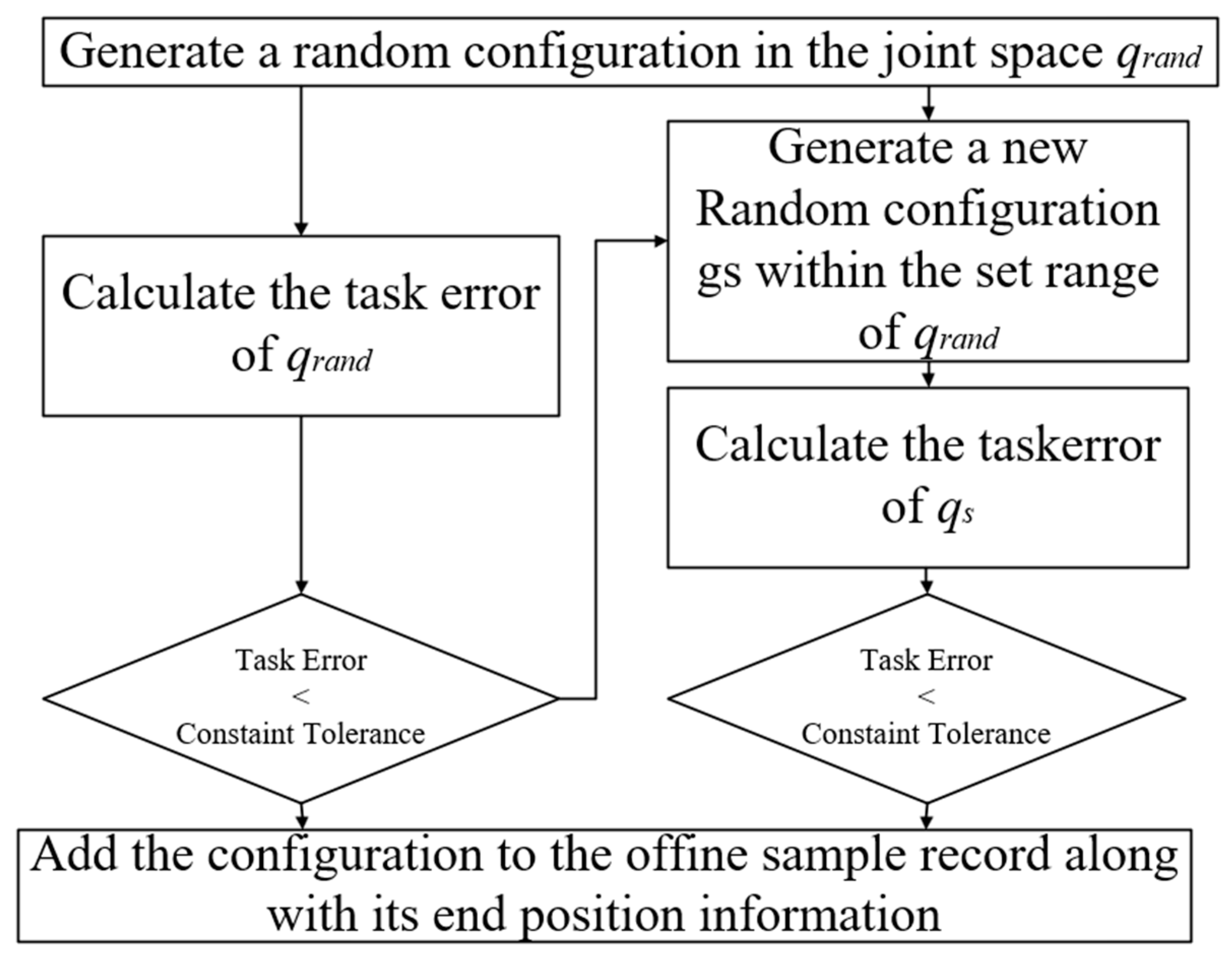
In this paper, an offline sampling set containing a large number of pose constraint configurations is constructed in advance to approximately describe the constraint manifold. The fundamental concept behind forming the sampling set is to randomly create the initial configuration in the joint space and assess whether or not it is a potential target configuration . By using the idea of continuous sampling and approximation of the Monte Carlo method, can be randomly generated as much as possible until the whole configuration space is obtained, which ensures the probability completeness. When judging that the random mechanism type is not in the constraint manifold, in order to accelerate the random sampling rate in advance, this paper incorporates the idea of the stochastic gradient descent method to select a new configuration within a certain range near and re-judge it.
The flowchart shown in Figure 1 can be broken down into five steps, as follows:
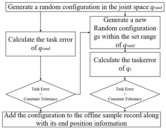
Figure 1.
Flow diagram of off-line data set construction.
Step 1: A random mechanism type is generated in the joint space and the task error of is calculated according to the task error formula.
Step 2: To determine whether the is on the constrained manifold, if < , then the is identified as the configuration that satisfies the target constraint.
Step 3: Conversely, if the is not on the constrained manifold, then new configurations are randomly selected within a specified range of the , and their task errors are calculated to determine whether the task errors of the are less than those of . Then the is replaced by .
Step 4: The iterative process is repeated until the task error meets the constraint tolerance . In this case, the is identified as the configuration that satisfies the target constraint.
Step 5: If the task error of the obtained configurations is still greater than the constraint tolerance within the set number of iterations, it will fail and return to step 1.
2.4. Informed Bidirectional Quick-RRT* Algorithm
2.4.1. Multi-Objective Bias Strategy
In the Bi-Quick-RRT* algorithm, the sampling points generated by double trees are random and single, and lack the ability to jump out of local traps when dealing with complex obstacles; there is also the lack of search efficiency when dealing with simple obstacles, which means there is the lack of adaptability to obstacles of different complexity. Because the multi-objective bias strategy is added to solve this problem, the core idea of the strategy is to extend the sampling process of random tree to three biased samples. Each biased sample has different effects.
- Tree 1 and tree 2 randomly pick points in the whole map. The purpose is to enhance the ability to jump out of the obstacle area faster when facing more complex obstacles, reduce the number of invalid samples, and improve the sampling efficiency.
- Tree 1 takes the starting point of tree 2 as the biased target for sampling points, and tree 2 takes the starting point of tree 1 as the biased target for sampling points. The purpose is to ensure the overall direction of random sampling and ensure the efficiency of the algorithm.
- Tree 1 uses the previous sampling point of tree 2 as a biased target for sampling points, and tree 2 uses the previous sampling point of tree 1 as a biased target for sampling points. The purpose is to speed up the connection of double trees and shorten the path process when facing simple and uncomplicated obstacles.
Depending on the complexity of the obstacles in the environment, different purposes can be achieved by changing the probability of the occurrence of each mining point. The pseudo-code for the multi-target bias strategy is provided in Algorithm 1.
| Algorithm 1: InformedSampleFree Function. |
2.4.2. Informed Bidirectional Quick-RRT* algorithm
To enhance the RRT exploration efficiency, the algorithm reduces the time spent solving the effective path. Informed-Bi-Quick-RRT* adds two optimization processes to the RRT algorithm: selecting the optimal parent node and pruning, and using the triangle inequality theorem to optimize the random tree structure [36]. This enlarges the traceability range of the two optimization processes and enhances the initial path to a certain extent while ensuring asymptotic optimization [37].
On this basis, the new algorithm incorporates the idea of double-tree expansion, starts randomly sampling from the starting point and the end point at the same time to find possible paths, and finally connects the two trees to determine a complete feasible path, which greatly improves the convergence speed [38].
However, since the randomly generated tree nodes are randomly distributed in the map, the generated random points are too scattered. In this paper, the sampling process of the random tree is extended to three-stage bias sampling in combination with the multi-objective bias expansion strategy mentioned above, and the algorithm is improved. The optimized algorithm can adjust the probability of three-stage sampling according to the complexity of the actual environment, and the algorithm can better deal with simple or complex obstacle environments.
The pseudo-code for the Informed-Bi-Quick-RRT* algorithm is provided in Algorithm 2.
| Algorithm 2: Informed-Bi-Quick-RRT*. |
The Informed-Bi-Quick-RRT* runs as follows:
- 1.
- The InformedSampleFree() function is used to generate random sampling points for both trees. Algorithm 2 presents the pseudocode for the InformedSampleFree() function. In the exploration process, the two trees are consistent in steps 2 through 4, so the related steps use the same expression.
- 2.
- Two new nodes are used: and . The Nearest (, ) function should be used to produce , and the Steer (, , δ) function should be used to create .
- 3.
- Under the premise that there is no collision between and , the path from to is optimized. The Near (, , ) and Ancestry (, , ) functions are used to identify the potential parent node of . Then, the ChooseParent (‘ ∪ , ) function is used to select the parent node in the potential parent node, so that the path distance from to is the smallest; finally, the Link (, ) function is used to form .
- 4.
- The path from to the midpoint of is optimized. The Ancestry (, , ) function is used to find the parent node of ; the and are used as the potential parent nodes of the midpoint of , and the Rewire (, ∪ ) function is used to find the parent node at the potential parent node, so that the path distance is minimized.
- 5.
- The Connect (, ) function is used to connect and . Firstly, the nodes closest to in : are determined, and then continuously advances δ with as the goal until they encounter obstacles or link to .
- 6.
- The FillPath (, ) function is used to stitch paths. In the case of a link between and , traces the parent node from to , thus forming the final . begins to trace the parent node to from the node connected to , thus forming the final .
- 7.
- The Swap (, ) function is used to exchange the contents of two trees, so that the number of nodes of the two trees remains balanced after several iterations.
3. Different Task Constraints in Dual-Arm Cooperative Systems
In the trajectory planning of heterogeneous two-arm collaboration, in order to ensure the relative consistency of the end-effector postures in collaboration so that the heterogeneous two-arm collaboration system is able to meet higher task requirements, this paper investigates the relative motion of the end-postures in different types of collaborative motions, and realizes the adaptive planning from the trajectory of the robot arm through the establishment of different kinematic constraint relations. According to the different motion constraint relationships between the arms, the two-arm cooperative motion can be broadly categorized into loose-constraint cooperative motion and tight-constraint cooperative motion.
3.1. Collaborative Movement with Loose Constraints
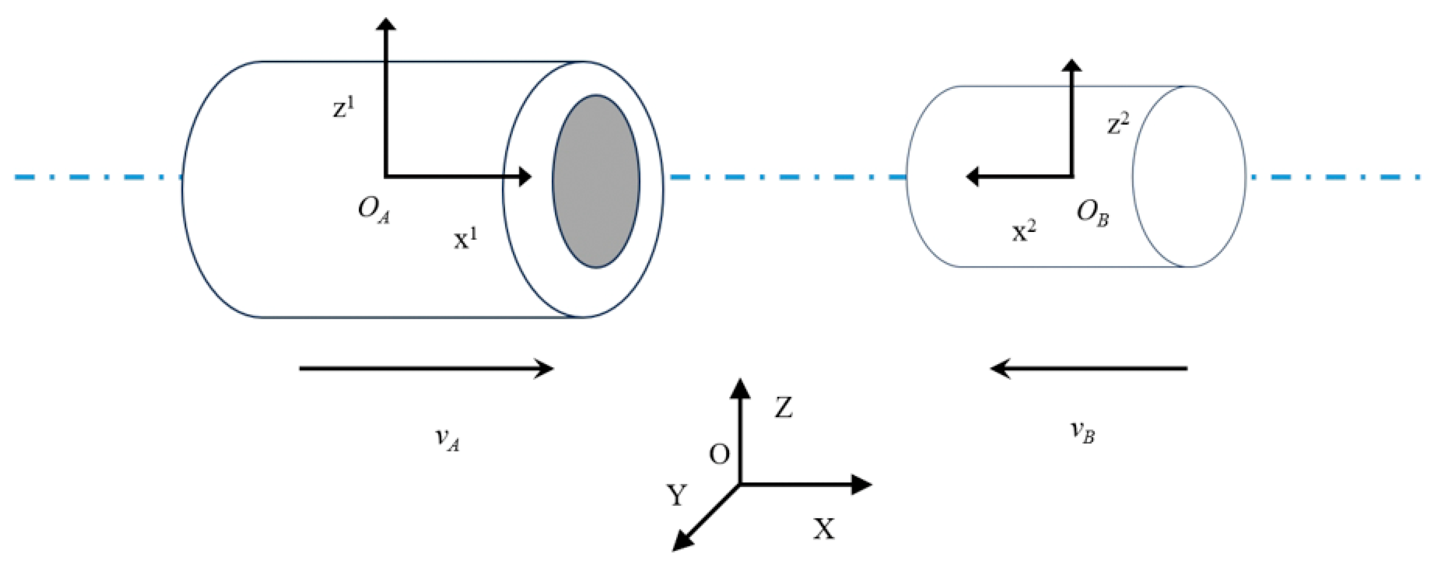
There are relatively strict constraints in the coordinated motion of the two arms under loose constraints. The two arms and the manipulated object will form a semi-closed chain system with a certain constraint relationship but not completely closed. In the typical pine cooperative assembly task [39], the dual-arm end-effector is required to perform relative motion on the same horizontal line with a fixed attitude, as shown in Figure 2.
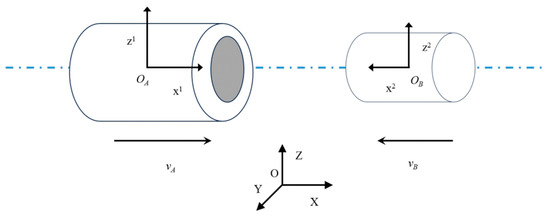
Figure 2.
Axle hole assembly relative pose diagram.
Suppose that the pose matrix of any point on the end-effector trajectory of the master robot is ,; then, is the pose transformation matrix from the base coordinate of the master robot to the point on the end-effector trajectory. Therefore, the pose matrix of the end-effector trajectory point at any time can be obtained as:
Let be the pose transformation matrix from the base coordinate of the manipulator to the base coordinate of the main manipulator, and be the pose matrix of the trajectory point of the end-effector of the manipulator under the base coordinate of the main manipulator. is the pose matrix of the trajectory point of the end-effector of the slave manipulator under the base coordinate of the slave manipulator. Then the pose matrix of the trajectory point of the end-effector of the slave manipulator under the base coordinate of the main manipulator can be obtained as follows:
According to the constraint between the trajectory points at the end of the master–slave manipulator, the pose matrix of the trajectory points at the end of the slave manipulator under the base coordinate of the master manipulator is solved:
Among them: is the pose matrix of the trajectory from the end point of the robot actuator under the base coordinate of the main manipulator.
By using Formulas (8) and (9), we can obtain:
Therefore, the pose matrix of the end point of the slave manipulator under the base coordinate of the slave manipulator can be obtained as follows:
From Equation (11), it can be seen that the end point pose of the slave manipulator can be solved under the condition of obtaining the base coordinate pose relationship matrix of the master–slave manipulator and the relative motion pose constraint of the end point and the end point pose of the master manipulator, so as to realize the adaptive planning of the slave manipulator trajectory according to the trajectory of the master manipulator.
3.2. Collaborative Movement with Tightly Constraints
The dual-arm cooperative motion under tight constraints has the strictest constraints on the motion process, which means that the dual arms and the operated object form a closed chain system with complete constraints [39]. In a typical tight cooperative task handling task [40], there is no relative motion between the dual-arm end-effector and the object to be carried, and the relative pose of the dual-arm end-effector is required to remain unchanged, as shown in Figure 3.

Figure 3.
Handling relative pose diagram.
The key point is to ensure that when the end-effector of the main arm moves from the point to the point, the pose relationship between the point and the point is equal to that between the point and the point in the process of moving the end-effector of the manipulator from to . The specific kinematics derivation is as follows:
When the pose transformation matrix from the robot base coordinate to the master robot base coordinate is set as , the pose relationship from the point to the point is , and the pose relationship from to is .
Since the relative pose relationship between the main manipulator and the end-effector of the slave manipulator remains unchanged at all times, the following relationship is satisfied:
Then:
Let and be the pose matrix of the and points in the master arm coordinate system, and and be the pose matrix of the and points in the slave arm coordinate system. Then the coordinates of the and points under the base coordinates of the main manipulator are:
Since , , , and constitute a complete closed chain of motion rings, they are obtained using Formulas (12) and (13):
From Formulas (14), (17) and (18), the following can be obtained:
The position of the slave manipulator in the base coordinate is:
By solving the inverse solution of , the angle value of each joint of the slave manipulator can be obtained. The slave manipulator can achieve the specified pose and position of the end point, so as to realize the adaptive planning of the slave manipulator trajectory according to the trajectory of the main manipulator.
4. Experiment
This research focuses on the dual-arm cooperation system composed of UR5 and UR10. MATLAB 2022b was used as the simulation software to complete the simulation of the algorithm and the system model construction.
The Informed-Bi-Quick-RRT* algorithm proposed in this paper was simulated with the RRT*, Quick-RRT*, and Bi-Quick-RRT* algorithms in different two-dimensional environments. It has been demonstrated that the new algorithm exhibits fast convergence speed, a short search path, and adaptability to various obstacle environments.
The simulation of both loose and close collaboration tasks in a 3D environment demonstrates the effect of the pre-sampling planning algorithm on the horizontal constraints of different end-effectors, as well as the rationality of adaptive planning for dual-arm trajectories.
Finally, the simulation environment for close cooperative motion includes the addition and simulation of obstacles. The simulation results demonstrate the ability of the Informed-Bi-Quick-RRT* algorithm, based on advanced sampling, to handle the horizontal and obstacle avoidance constraints of the end-effector. The results also prove the adaptability of the new algorithm to multi-constraint environments.
4.1. Algorithm Comparison
To demonstrate the adaptability of the new algorithm to complex obstacle environments, the experiment compared its performance in two environments: one simple and one complex. To reduce the impact of random sampling, the experiment recorded and summarized the average results of each algorithm after 20 runs, including path length, running time, and number of sampling nodes.
4.1.1. Simple Environment
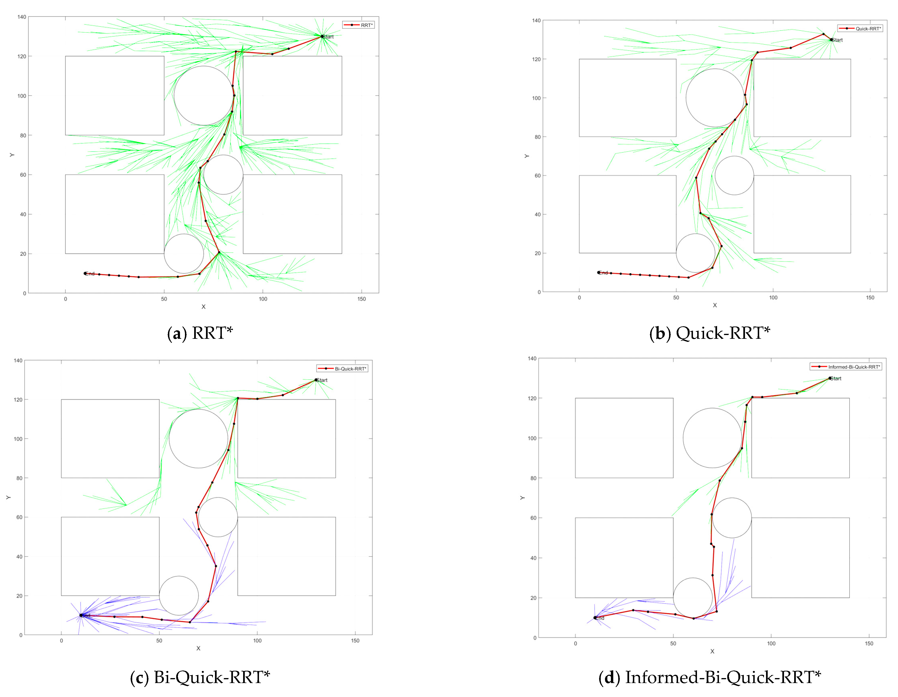
The results of algorithm comparison in a simple environment are shown in Figure 4, The simple environment shows a 1400 mm × 1400 mm environment containing four matrices and three circular obstacles. The start point is located in the upper right corner and the end point is located in the lower left corner. The red line represents the last viable path generated, while the green and blue lines represent the branches generated by the two trees, respectively.
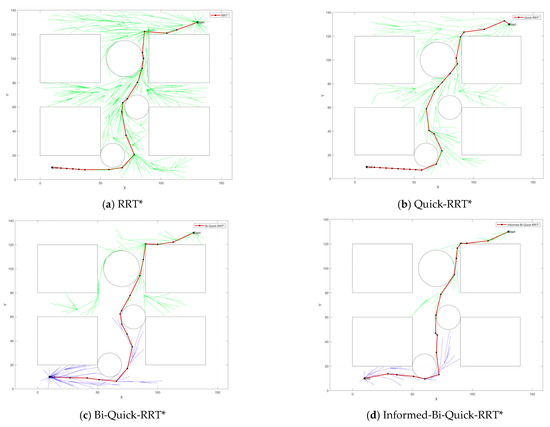
Figure 4.
Algorithm comparison in a simple environment.
Table 1 provides the specific statistics in a simple environment. As can be seen in Figure 4a), the RRT* algorithm performs a large number of random samples in the environment and has a large number of redundant calculations, resulting in a very pronounced inflection point in the final trajectory. Figure 4b) shows the effect of the Quick-RRT* algorithm on the optimization of node links. Compared to the RRT* algorithm, the number of path nodes is reduced by 28.8%, the generation of prominent inflection points is reduced, and the final trajectory is clearer and smoother. In addition, the computational cost is greatly reduced and the overall execution time is correspondingly reduced by 64%. The Bi-Quick-RRT* algorithm in Figure 4c) generates two trees simultaneously on the basis of the above, further improving the search efficiency of the algorithm and reducing the running time by 28.2%. Figure 4d) shows the planning effect of the Informed-Bi-Quick-RRT* algorithm. In a simple environment, according to the multi-objective bias strategy, the probability of the third segment is increased to speed up the connection speed and shorten the path length. It is not difficult to find in Table 1 that the new algorithm has fewer redundant nodes and branches, and shorter path length. Compared with the basic algorithm, the search efficiency of the new algorithm is improved by 94.3%, which meets the actual working requirements of the robot arm and proves the superiority of the new algorithm.

Table 1.
Simple environment algorithm comparison table.
4.1.2. Complex Environment
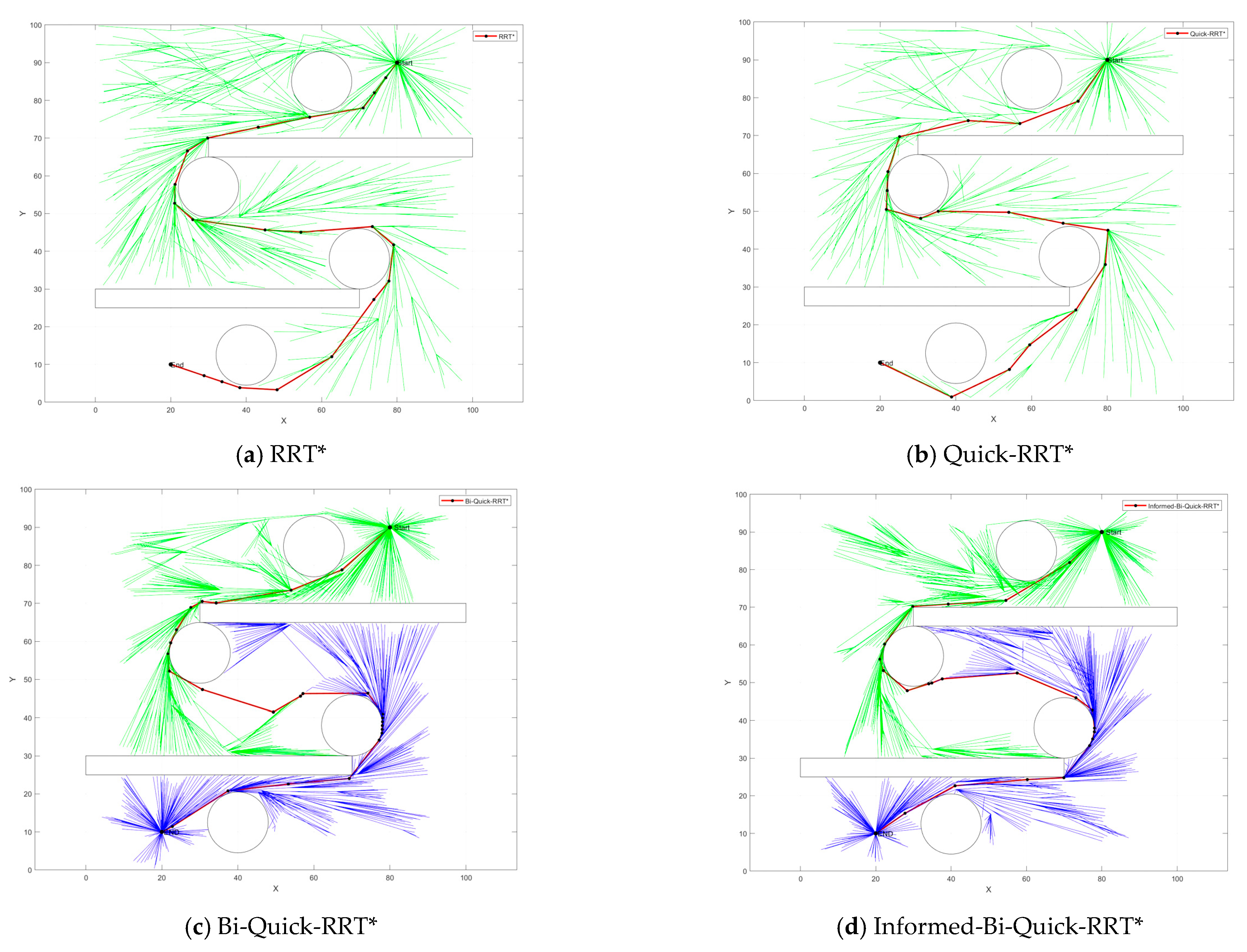
Figure 5 depicts a more complex environment, which includes two rectangular and four circular obstacles. This change in the position of the obstacles results in a more winding possible driving path.
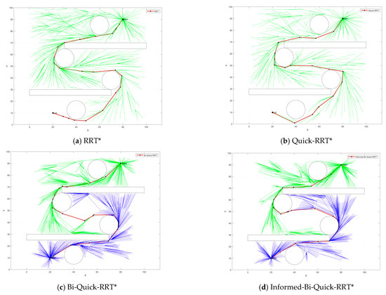
Figure 5.
Algorithm comparison in a complex environment.
Table 2 provides specific statistics in a complex environment. When analyzing Figure 5a–c, it becomes apparent that in a more complex environment, the Quick-RRT* and Bi-Quick-RRT* algorithms have significant advantages over RRT*. Specifically, the number of path nodes is reduced by 25.6% and 27.4%, respectively, and the time is shortened by 72.3% and 76.7%, respectively.

Table 2.
Algorithm comparison in complex environment.
In the face of a complex environment, the new algorithm improves the probability of occurrence of the first paragraph according to the multi-objective bias strategy to improve the ability of the random tree to jump out of the obstacle area and reduce the generation of redundant nodes, as shown in Figure 5d). According to Table 2, the running time of the new algorithm is further reduced by 36.5%, the number of path nodes is further reduced by 17.4%, and the comprehensive search efficiency is increased by 85.2%. This shows that the algorithm has a strong ability to deal with complex obstacles.
To summarize, in comparison with traditional planning algorithms, the Informed-Bi-Quick-RRT* algorithm has clear advantages in terms of convergence speed, path length, and quality, and performs well in various obstacle environments. In straightforward environments, this technique can significantly accelerate path generation. In more complicated environments, it can assist branches in avoiding obstacles more effectively.
4.2. Three-Dimensional Simulation Considering Horizontal Constraints
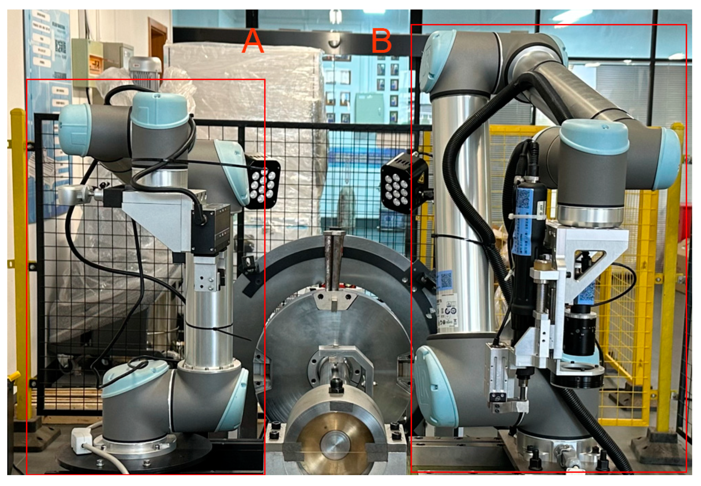
The UR5 and UR10 manipulators used in the laboratory are both six-degree-of-freedom serial manipulators. They are widely used in mechanical operations because of their programming simplicity, high flexibility, and high safety. The actual working environment of the dual-arm cooperative system is shown in Figure 6. A is the UR5 manipulator, and B is the UR10 manipulator.
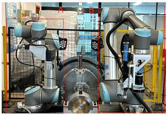
Figure 6.
Real environment of the two-arm collaboration system.
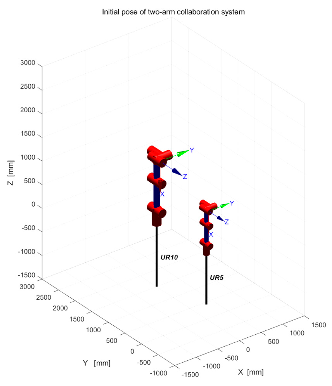
According to the Denavit–Hartenberg (DH) parameters shown in Table 3 and Table 4, the UR5 and UR10 manipulator models are defined respectively, as shown in Figure 7.

Table 3.
UR5 D-H Table.

Table 4.
UR10 D-H Table.
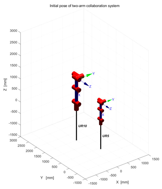
Figure 7.
Initial pose of two−arm collaboration system.
According to the transformation principle of the coordinate system and the establishment rule of the D–H coordinate system, the forward transformation matrix between adjacent joint coordinate systems can be derived, that is, the D–H transformation matrix, as shown in Formula (21).
The transformation matrix that is homogeneous between the UR series manipulator base and the end-effector in the Cartesian coordinate system is as follows:
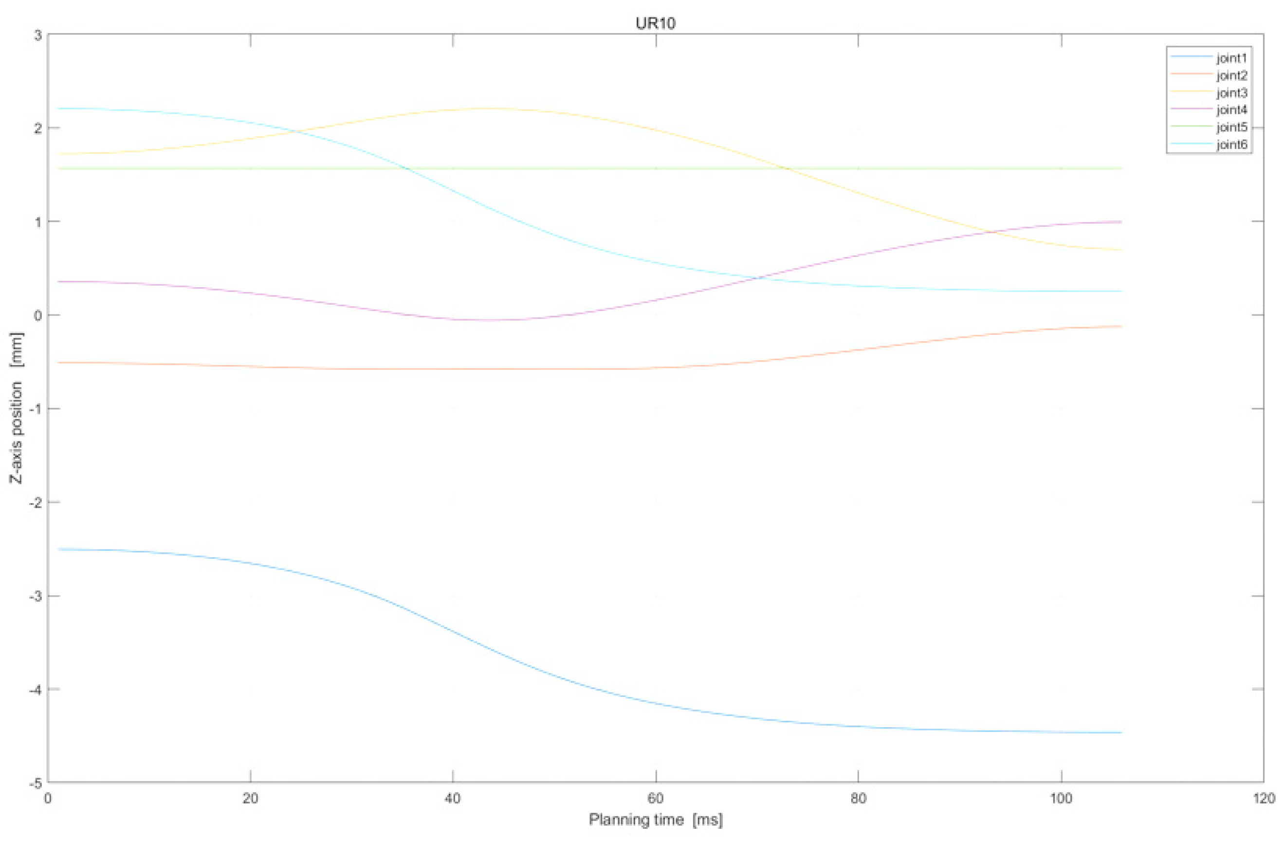
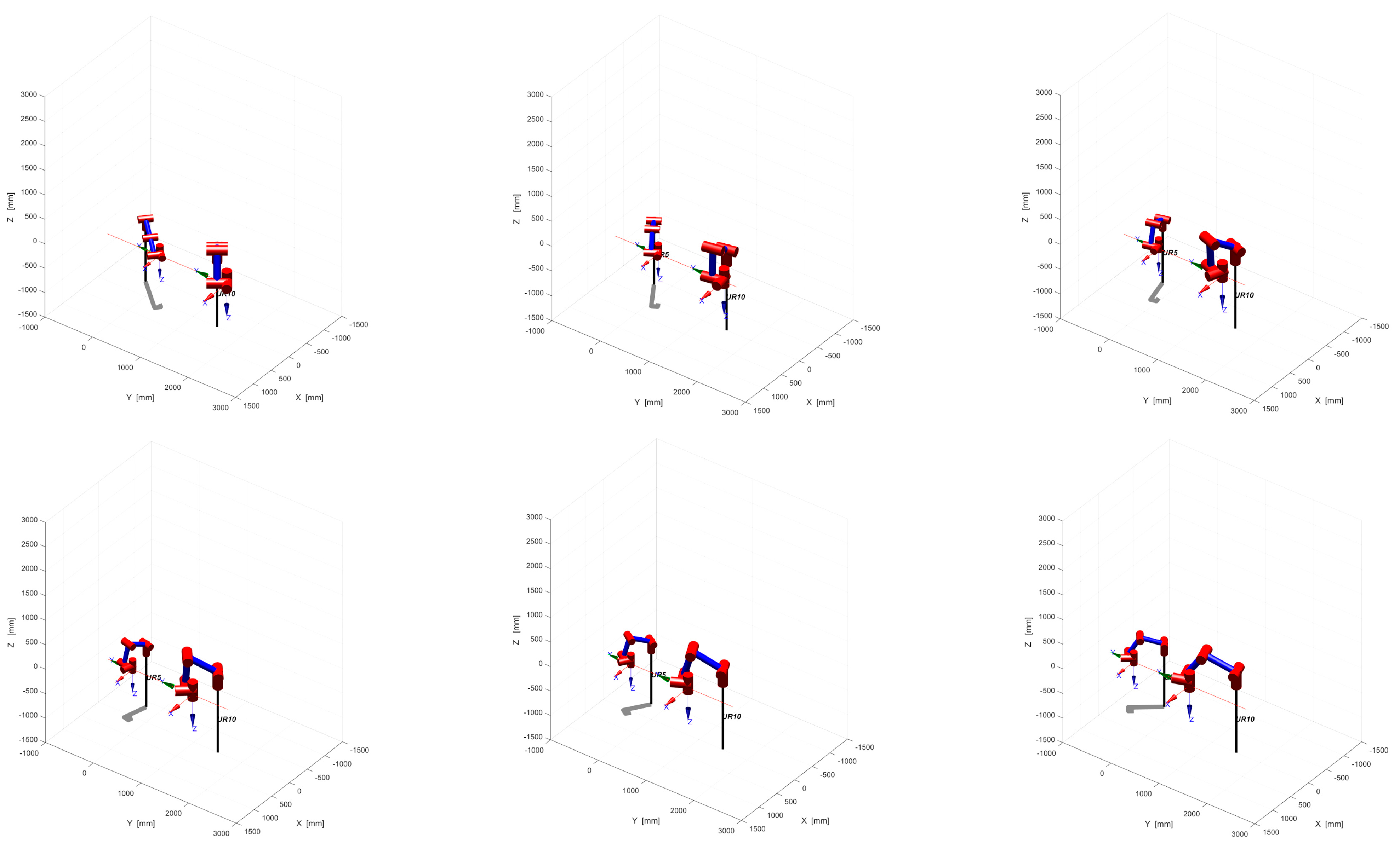
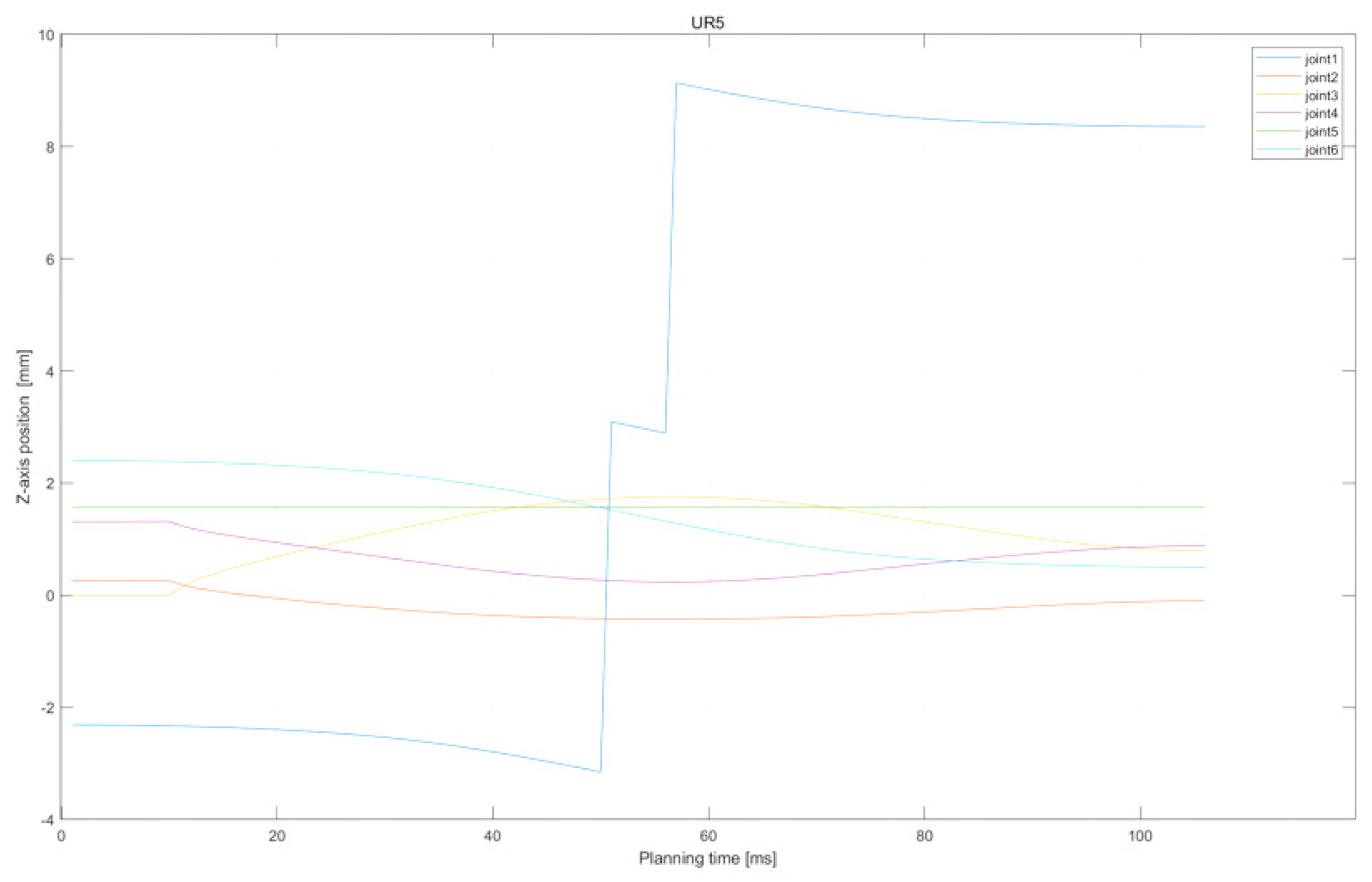
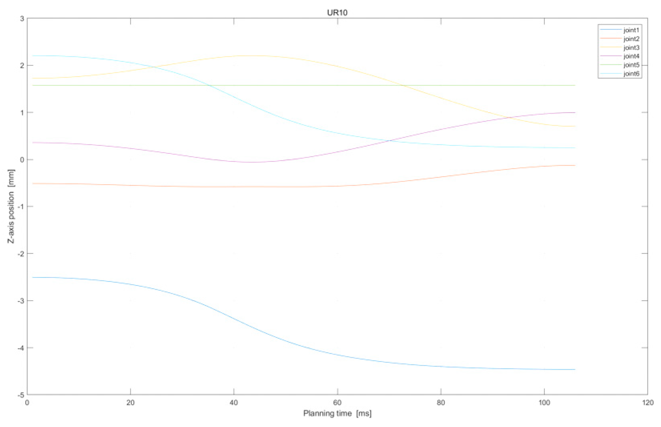
We take the two-arm collaborative model built in the laboratory environment as the research object, with UR5 as the main robot arm and UR10 as the slave robot arm, and perform the assembly task and the handling task, respectively, through the master–slave control. In both tasks, the horizontal constraint of the end-effector and the dynamic constraint between the two arms are considered. We use a series of postures taken at fixed time intervals to show the movement of the task, and a joint position graph to show the changes of all joints.
4.2.1. Loose Collaborative Motion: Assembly Task
The objective of the assembly task is to hold objects horizontally and assemble them on a level plane. Throughout the assembly process, it is necessary for the end-effector of the two arms to maintain a horizontal attitude constantly, whilst the joint motion is smooth.
The simulated diagram of the dual-arm collaborative system’s pose is depicted in Figure 8. Specifically, the poses at 0 s, 2 s, 4 s, 6 s, 8 s, and 10 s were selected for observation. The steady convergence of the arms during the assembly process, while the end-effector maintains a Y-axis level, can be observed. This conforms to the attitude relationship required during the said assembly process.
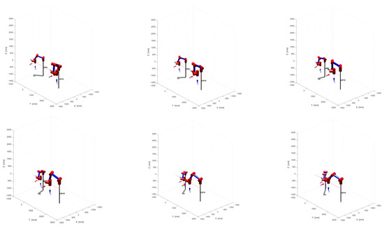
Figure 8.
Cooperative system’s position of assembly task.
Further, Figure 9 and Figure 10 display the joint position variations of the two arms. From the green dot on the diagram, it is evident that the end-effector remains at a constant position of 150 mm whilst maintaining the same horizontal line and smooth joint changes.
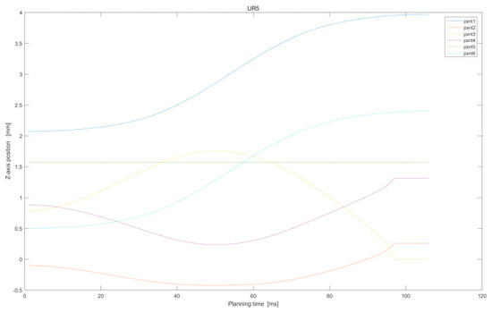
Figure 9.
Z−axis position of UR5 in assembly task.
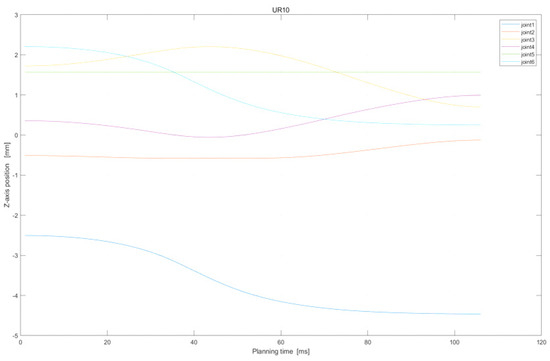
Figure 10.
Z−axis position of UR10 in assembly task.
4.2.2. Tightly Collaborative Motion: Handling Task
The goal of the handling task is to carry objects with two arms. During the motion, the end-effector of the two arms must maintain the same level of posture at all times; then, the joint motion is smooth.
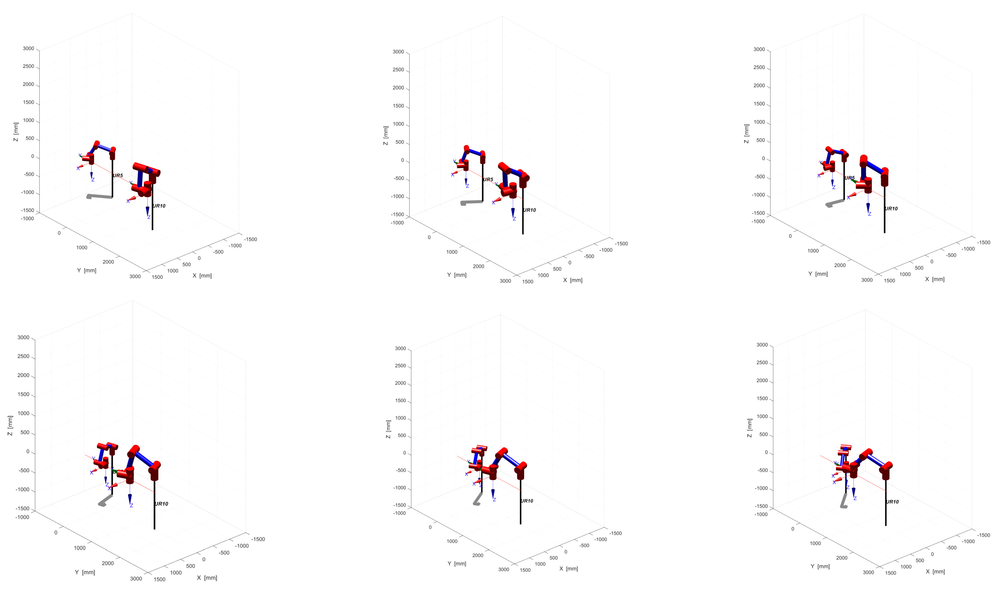
The position of the dual-arm cooperative system during the handling task is depicted in Figure 11, showcasing six different moments: 0 s, 2 s, 4 s, 6 s, 8 s, and 10 s. As demonstrated, the arms move synchronously throughout the handling process, and the end-effector stays levelled along the Y-axis, thus adhering to the required attitude relationship.

Figure 11.
Cooperative system’s position of handling task.
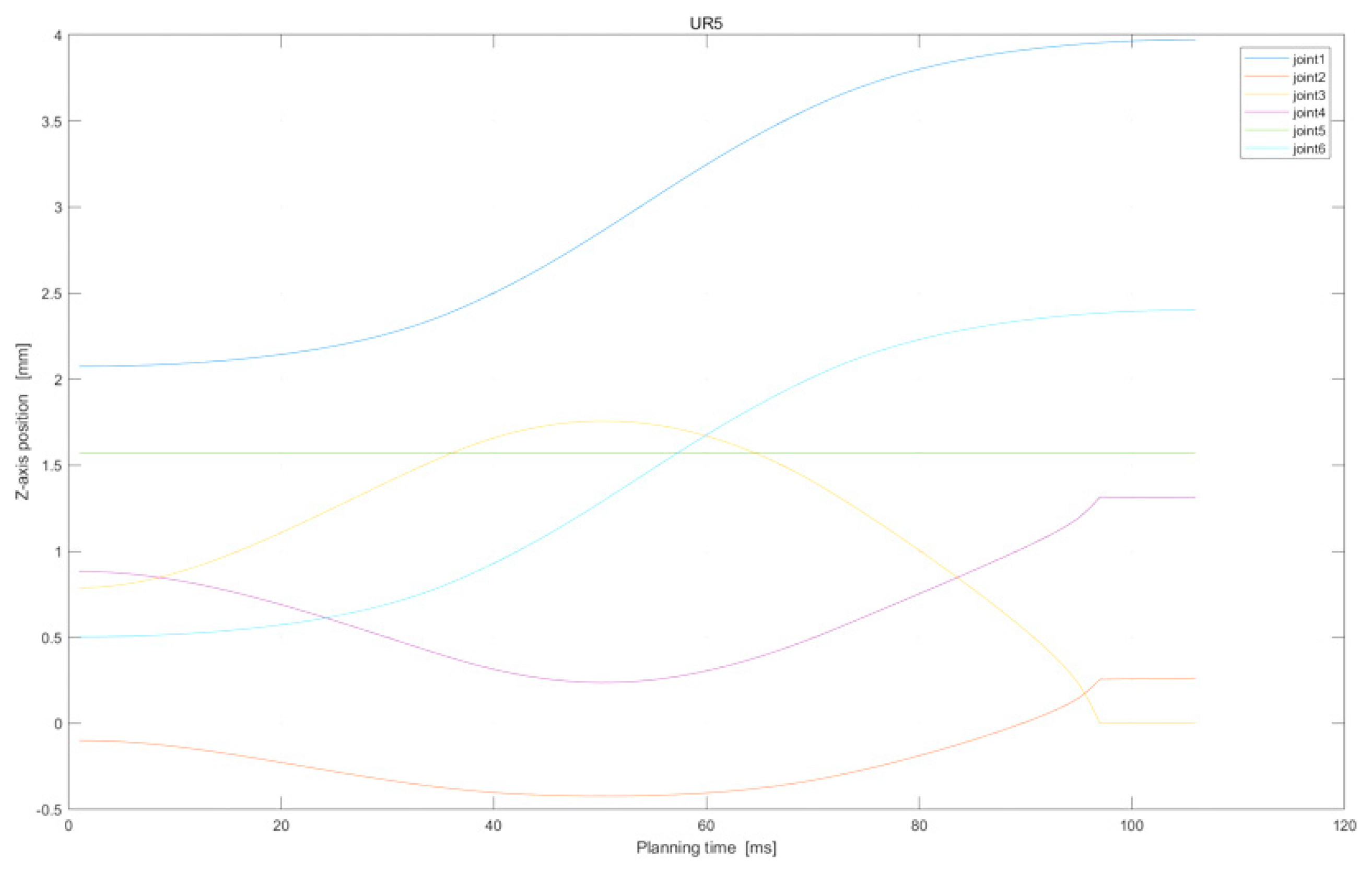
Moreover, Figure 12 and Figure 13 present the handling task variations in the joint position of the main–slave manipulator. From the end-effector joint represented by the green component in the figure, it can be observed that the end-effector remains at a fixed position of 175 mm whilst maintaining the same horizontal alignment and smooth joint movement.
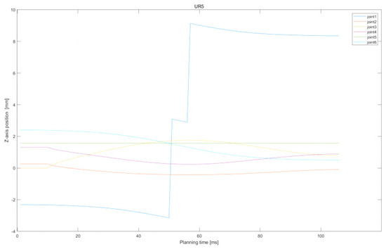
Figure 12.
Z-axis position of UR5 in handling task.
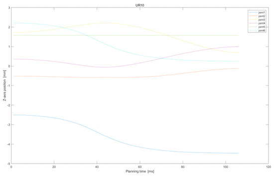
Figure 13.
Z-axis position of UR10 in handling task.
In summary, the above two motion processes realized by the offline sampling-based motion-planning method preliminarily demonstrate the effectiveness of this method in dealing with end-effector constraints and horizontal direction constraints.
4.3. Three-Dimensional Simulation Considering Multiple Constraints
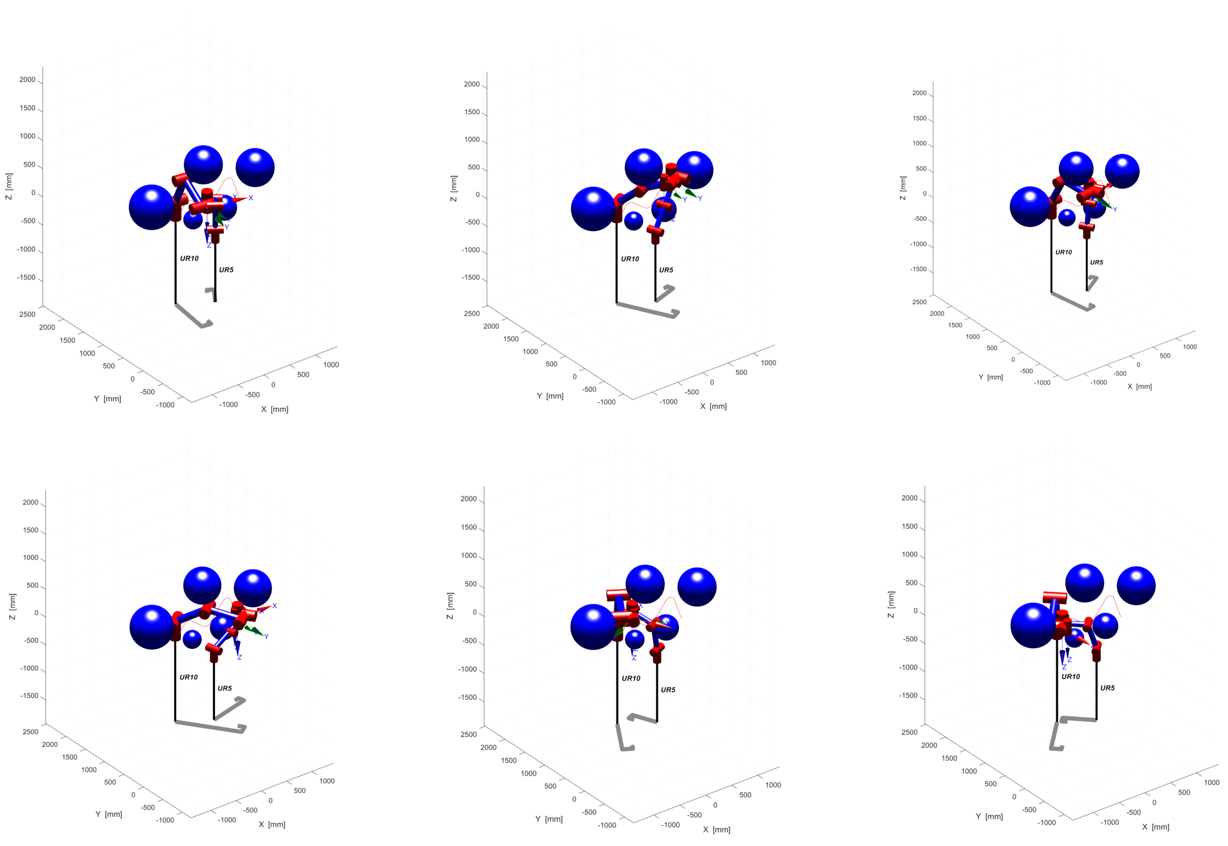
In Section 4.2, we simulate the two tasks of assembly and handling, focusing on the directional constraints. The experimental results show that the directional constraints of the end-effector have been well handled. Based on this, we now need to consider additional obstacle avoidance constraints for the handling task. To test the motion-planning effect of the Informed Bi-Quick RRT* algorithm, we set up a 3000 mm × 4000 mm × 4500 mm map and placed five dark blue spherical obstacles with different radii on the 3D map. We set the right side as the start point of the moving task and the left side as the end point of the moving task. Throughout the handling process, we needed the two-armed end-effectors to maintain a horizontal position and be able to avoid obstacles and collisions.
As shown in Figure 14, the two-arm collaborative system obtains a collision-free and smooth path after running the simulation. In the actual handling process, the end-effector of both arms can complete the handling task by following this collision-free path.
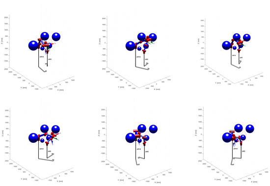
Figure 14.
Cooperative system’s position.
Figure 14 shows the complete process of moving both arms from the predetermined start point to the target end point, confirming that the algorithm is efficient and feasible as there is no collision with surrounding obstacles and the end-effector direction obeys horizontal holding constraints throughout the movement.
5. Conclusions
This paper presents an Informed Bi-Quick RRT* algorithm for rational motion planning of two-arm cooperative systems under multiple constraints. The algorithm is based on offline sampling and rich data sets, and the offline sampling time is reduced by incremental construction and random gradient descent. However, the traditional Quick-RRT* algorithm is enhanced by integrating a two-tree concept and a multi-objective bias expansion strategy. In this paper, simulation experiments are conducted in two obstacle environments with different complexity levels. The results show that compared with other traditional algorithms, the computation time of the proposed algorithm is reduced by about 70% and the number of path nodes is reduced by about 40%, which proves the superiority of the new algorithm. In addition, the directional constraints in the two-arm cooperative system are analyzed in detail, and the adaptive planning effect of the two-arm trajectory is demonstrated through the three-dimensional simulation of the assembly and transportation tasks, and it is verified that the loosely constrained cooperative motion algorithm and the tightly constrained cooperative motion algorithm can accurately describe the nonlinear kinematic constraints between the two arms. Finally, in the handling task, a three-dimensional motion simulation of the two-arm cooperative system is performed considering obstacle avoidance and directional constraints. The system runs stably and avoids possible collisions while maintaining the level of the end-effector, demonstrating the feasibility and effectiveness of the proposed algorithm.
In summary, the motion-planning technology based on offline sampling can shorten the subsequent planning time by sampling the basic constrained manifolds in advance and generating sample databases that satisfy the constraints. However, although the offline sampling process is optimized in this paper, a large number of offline computations are inevitably required to satisfy more constraints. Second, although the offline database can be continuously supplemented and improved, it is not as flexible as the real-time planning method. In order to adapt to a changing external environment, the method based on offline sampling needs to introduce some online planning elements to cope with the changing obstacle configuration and possible fault edges in the offline calculation roadmap.
Author Contributions
Conceptualization, Q.Z. and Y.L.; methodology, Y.L.; software, Q.Z. and J.D.; validation, Q.Z. and J.Q.; formal analysis, Y.L. and J.D.; investigation, Y.L.; resources, Y.L.; data curation, Q.Z. and Y.L.; writing—original draft preparation, Y.L.; writing—review and editing, J.Q.; supervision, J.D.; project administration, Q.Z.; funding acquisition, Y.L. All authors have read and agreed to the published version of the manuscript.
Funding
This research received no external funding.
Data Availability Statement
Data will be made available on request.
Conflicts of Interest
The authors declare no conflicts of interest.
References
- Qu, J.; Zhang, F.; Wang, Y.; Fu, Y. Human-like coordination motion learning for a redundant dual-arm robot. Robot. Comput. Integr. Manuf. 2019, 57, 379–390. [Google Scholar] [CrossRef]
- Choset, H.; Lynch, K.M.; Hutchinson, S.; Kantor, G.A.; Burgard, W. Principles of Robot Motion: Theory, Algorithms, and Implementations; MIT Press: Cambridge, MA, USA, 2005. [Google Scholar]
- Vahrenkamp, N.; Asfour, T. Representing the robot’s workspace through constrained manipulability analysis. Auton. Robot. 2015, 38, 17–30. [Google Scholar] [CrossRef]
- Gammell, J.D.; Strub, M.P. Asymptotically optimal sampling-based motion planning methods. Annu. Rev. Control. Robot. Auton. Syst. 2021, 4, 295–318. [Google Scholar] [CrossRef]
- Liebenwein, L.; Baykal, C.; Gilitschenski, I.; Karaman, S.; Rus, D. Sampling-based approximation algorithms for reachability analysis with provable guarantees. In Proceedings of the of Robotics: Science and Systems 2018, Pittsburgh, PA, USA, 26–28 June 2018. [Google Scholar]
- Yu, F.; Shang, H.; Zhu, Q.; Zhang, H.; Chen, Y. An efficient RRT-based motion planning algorithm for autonomous underwater vehicles under cylindrical sampling constraints. Auton. Robot. 2023, 47, 281–297. [Google Scholar] [CrossRef]
- Vonásek, V.; Pěnička, R. Sampling-based motion planning of 3D solid objects guided by multiple approximate solutions. In Proceedings of the 2019 IEEE/RSJ International Conference on Intelligent Robots and Systems (IROS), Macau, China, 3–8 November 2019; IEEE: Piscataway, NJ, USA, 2019. [Google Scholar]
- Zhou, C.; Huang, B.; Fränti, P. A review of motion planning algorithms for intelligent robots. J. Intell. Manuf. 2022, 33, 387–424. [Google Scholar] [CrossRef]
- Tamizi, M.G.; Yaghoubi, M.; Najjaran, H. A review of recent trend in motion planning of industrial robots. Int. J. Intell. Robot. Appl. 2023, 7, 253–274. [Google Scholar] [CrossRef]
- James, J.; Weng, Y.; Hart, S.; Beeson, P.; Burridge, R. Prophetic goal-space planning for human-in-the-loop mobile manipulation. In Proceedings of the 2015 IEEE-RAS 15th International Conference on Humanoid Robots (Humanoids), Seoul, Republic of Korea, 3–5 November 2015; IEEE: Piscataway, NJ, USA, 2015. [Google Scholar]
- Rakita, D.; Mutlu, B.; Gleicher, M. RelaxedIK: Real-time Synthesis of Accurate and Feasible Robot Arm Motion. In Proceedings of the Robotics: Science and Systems, Pittsburgh, PA, USA, 26–30 June 2018. [Google Scholar]
- Rakita, D.; Mutlu, B.; Gleicher, M. Stampede: A discrete-optimization method for solving pathwise-inverse kinematics. In Proceedings of the 2019 International Conference on Robotics and Automation (ICRA), Montreal, QC, Canada, 20–24 May 2019; IEEE: Piscataway, NJ, USA, 2019. [Google Scholar]
- Li, B.; Li, L.; Acarman, T.; Shao, Z.; Yue, M. Optimization-based maneuver planning for a tractor-trailer vehicle in a curvy tunnel: A weak reliance on sampling and search. IEEE Robot. Autom. Lett. 2021, 7, 706–713. [Google Scholar] [CrossRef]
- Bonalli, R.; Bylard, A.; Cauligi, A.; Lew, T.; Pavone, M. Trajectory optimization on manifolds: A theoretically-guaranteed embedded sequential convex programming approach. arXiv 2019, arXiv:190507654. [Google Scholar]
- Long, P.; Keleştemur, T.; Önol, A.Ö.; Padir, T. Optimization-based human-in-the-loop manipulation using joint space polytopes. In Proceedings of the 2019 International Conference on Robotics and Automation (ICRA), Montreal, QC, Canada, 20–24 May 2019; IEEE: Piscataway, NJ, USA, 2019. [Google Scholar]
- Kang, M.; Yoon, S.-E. Analysis and acceleration of TORM: Optimization-based planning for path-wise inverse kinematics. Auton. Robot. 2022, 46, 599–615. [Google Scholar] [CrossRef]
- Rakita, D.; Mutlu, B.; Gleicher, M. An analysis of RelaxedIK: An optimization-based framework for generating accurate and feasible robot arm motions. Auton. Robot. 2020, 44, 1341–1358. [Google Scholar] [CrossRef]
- Kim, D.; Kwon, Y.; Yoon, S.-E. Dancing prm: Simultaneous planning of sampling and optimization with configuration free space approximation. In Proceedings of the 2018 IEEE International Conference on Robotics and Automation (ICRA), Brisbane, QLD, Australia, 21–25 May 2018; IEEE: Piscataway, NJ, USA, 2018. [Google Scholar]
- Cheng, R.; Petersen, J.; Borders, J.; Helmick, D.; Kaul, L.; Kruse, D.; Leichty, J.; Matl, C.; Papazov, C.; Shankar, K.; et al. Motion Planning to Cartesian Targets Leveraging Large-Scale Dynamic Roadmaps. In Proceedings of the 2023 IEEE 19th International Conference on Automation Science and Engineering (CASE), Auckland, New Zealand, 26–30 August 2023; IEEE: Piscataway, NJ, USA, 2023. [Google Scholar]
- Wang, X.; Wei, J.; Zhou, X.; Xia, Z.; Gu, X. AEB-RRT*: An adaptive extension bidirectional RRT* algorithm. Auton. Robot. 2022, 46, 685–704. [Google Scholar] [CrossRef]
- Li, B.; Chen, B. An adaptive rapidly-exploring random tree. IEEE/CAA J. Autom. Sin. 2021, 9, 283–294. [Google Scholar] [CrossRef]
- Sun, C.; Liu, X.; Shen, R. Research on Collision Avoidance Path Planning of Dual Manipulator Robot Based on Fusion Algorithm. In Proceedings of the 2022 International Conference on Automation, Robotics and Computer Engineering (ICARCE), Wuhan, China, 16–17 December 2022; IEEE: Piscataway, NJ, USA, 2022. [Google Scholar]
- Kingston, Z.; Moll, M.; Kavraki, L.E. Exploring implicit spaces for constrained sampling-based planning. Int. J. Robot. Res. 2019, 38, 1151–1178. [Google Scholar] [CrossRef]
- Jaillet, L.; Porta, J.M. Path planning under kinematic constraints by rapidly exploring manifolds. IEEE Trans. Robot. 2012, 29, 105–117. [Google Scholar] [CrossRef]
- Berenson, D.; Srinivasa, S.S.; Ferguson, D.; Kuffner, J.J. Manipulation planning on constraint manifolds. In Proceedings of the 2009 IEEE International Conference on Robotics and Automation, Kobe, Japan, 12–17 May 2009; IEEE: Piscataway, NJ, USA, 2009. [Google Scholar]
- Mirabel, J.; Tonneau, S.; Fernbach, P.; Seppälä, A.-K.; Campana, M.; Mansard, N.; Lamiraux, F. HPP: A new software for constrained motion planning. In Proceedings of the 2016 IEEE/RSJ International Conference on Intelligent Robots and Systems (IROS), Daejeon, Republic of Korea, 9–14 October 2016; IEEE: Piscataway, NJ, USA, 2016. [Google Scholar]
- Mirabel, J.; Lamiraux, F. Handling implicit and explicit constraints in manipulation planning. In Proceedings of the of Robotics: Science and Systems 2018, Pittsburgh, PA, USA, 26–28 June 2018. [Google Scholar]
- Henderson, M.E. Multiple parameter continuation: Computing implicitly defined k-manifolds. Int. J. Bifurc. Chaos 2002, 12, 451–476. [Google Scholar] [CrossRef]
- Stilman, M. Global manipulation planning in robot joint space with task constraints. IEEE Trans. Robot. 2010, 26, 576–584. [Google Scholar] [CrossRef]
- Vendittelli, M.; Oriolo, G. Task-constrained motion planning for underactuated robots. In Proceedings of the IEEE International Conference on Robotics and Automation, Kobe, Japan, 12–17 May 2009. [Google Scholar]
- Kim, B.; Um, T.T.; Suh, C.; Park, F.C. Tangent bundle RRT: A randomized algorithm for constrained motion planning. Robotica 2016, 34, 202–225. [Google Scholar] [CrossRef]
- Wu, D.; Wei, L.; Wang, G.; Tian, L.; Dai, G. APF-IRRT*: An improved informed rapidly-exploring random trees-star algorithm by introducing artificial potential field method for mobile robot path planning. Appl. Sci. 2022, 12, 10905. [Google Scholar] [CrossRef]
- Burget, F.; Hornung, A.; Bennewitz, M. Whole-body motion planning for manipulation of articulated objects. In Proceedings of the 2013 IEEE International Conference on Robotics and Automation, Karlsruhe, Germany, 6–10 May 2013; IEEE: Piscataway, NJ, USA, 2013. [Google Scholar]
- Şucan, I.A.; Chitta, S. Motion planning with constraints using configuration space approximations. In Proceedings of the 2012 IEEE/RSJ International Conference on Intelligent Robots and Systems, Vilamoura-Algarve, Portugal, 7–12 October 2012; IEEE: Piscataway, NJ, USA, 2012. [Google Scholar]
- Kingston, Z.; Moll, M.; Kavraki, L.E. Sampling-based methods for motion planning with constraints. Annu. Rev. Control. Robot. Auton. Syst. 2018, 1, 159–185. [Google Scholar] [CrossRef]
- Karaman, S.; Frazzoli, E. Sampling-based algorithms for optimal motion planning. Int. J. Robot. Res. 2011, 30, 846–894. [Google Scholar] [CrossRef]
- Jeong, I.-B.; Lee, S.-J.; Kim, J.-H. Quick-RRT*: Triangular inequality-based implementation of RRT* with improved initial solution and convergence rate. Expert Syst. Appl. 2019, 123, 82–90. [Google Scholar] [CrossRef]
- Kuffner, J.J.; LaValle, S.M. RRT-connect: An efficient approach to single-query path planning. In Proceedings of the 2000 ICRA Millennium Conference, IEEE International Conference on Robotics and Automation Symposia Proceedings, (Cat No 00CH37065), San Francisco, CA, USA, 24–28 April 2000; IEEE: Piscataway, NJ, USA, 2000. [Google Scholar]
- Wang, Q.; Min, H.; Guo, Y. An algorithm for trajectory optimization of dual-arm coordination based on arm angle constraints. Cobot 2022, 1, 10. [Google Scholar] [CrossRef]
- Liu, F.; Ran, L.; Zhang, F. Structure Design and Dynamic Simulation Analysis of Dual-arm Handling Robot. In Proceedings of the 2021 2nd International Conference on Artificial Intelligence and Information Systems, Hangzhou, China, 5–7 November 2021. [Google Scholar]
Disclaimer/Publisher’s Note: The statements, opinions and data contained in all publications are solely those of the individual author(s) and contributor(s) and not of MDPI and/or the editor(s). MDPI and/or the editor(s) disclaim responsibility for any injury to people or property resulting from any ideas, methods, instructions or products referred to in the content. |
© 2024 by the authors. Licensee MDPI, Basel, Switzerland. This article is an open access article distributed under the terms and conditions of the Creative Commons Attribution (CC BY) license (https://creativecommons.org/licenses/by/4.0/).

