Abstract
The flywheel energy storage system (FESS) of a mechanical bearing is utilized in electric vehicles, railways, power grid frequency modulation, due to its high instantaneous power and fast response. However, the lifetime of FESS is limited because of significant frictional losses in mechanical bearings and challenges associated with passing the critical speed. To suppress the unbalanced response of FESS at critical speed, a damping ring (DR) device is designed for a hybrid supported FESS with mechanical bearing and axial active magnetic bearing (AMB). Initially, the dynamic model of the FESS with DR is established using Lagrange’s equation. Moreover, the dynamic parameters of the DR are obtained by experimental measurements using the method of free vibration attenuation. Finally, the influence of the DR device on the critical speed and unbalanced response of FESS is analyzed. The results show that the designed DR device can effectively reduce the critical speed of FESS, and increase the first and second mode damping ratio. The critical speed is reduced from 13,860 rpm to 5280 rpm. Compared with FESS of the mechanical bearing, the unbalanced response amplitude of the FESS with DR is reduced by more than 87.8%, offering promising technical support for the design of active and passive control systems in FESS.
1. Introduction
The rapid development of electric vehicles has been facilitated by the implementation of the dual-carbon strategy. However, conventional batteries encounter several challenges as a result of the frequent braking and starting of electric vehicles in the city. To enhance the lifetime of traditional batteries, a variety of new energy storage devices have gained attention. Currently, the FESS has emerged as a focal point of research due to its characteristics of high instantaneous power, fast response speed, and long lifetime [1,2,3,4,5]. The bearing is the key component of the FESS, as it determines several vital characteristics such as self-discharge, lifetime, maintenance intervals, and most importantly, cost [6]. In FESS, the bearings mainly include mechanical bearings [7,8,9], permanent magnet bearings (PMBs) [10,11], active magnetic bearings (AMBs) [12,13], and superconducting magnetic bearings (SMBs) [14,15]. At present, mechanical bearings are utilized in FESS to better address the complex vehicle conditions [7]. Nevertheless, mechanical bearings suffer from high friction loss, low lifetime, and challenges in surpassing critical speeds [8].
To solve this problem, the current trend is to combine different types of bearings, and active control combined with conventional bearing has a positive effect on rotor–bearing systems [16,17]. By integrating AMBs with mechanical bearings, the axial pressure on the latter is mitigated. This results in a reduction of bearing friction loss, leading to improved charging efficiency and extended bearing lifetime [18,19]. In [20], the predominant portion of the bearing load spectrum is mitigated by utilizing elastic bearing supports and AMBs. Simultaneously, the cost of on-board FESS is reduced and the lifetime is increased. Furthermore, FESS combining AMBs with mechanical bearings has been applied in companies [21]. While the friction loss of mechanical bearings is reduced by AMB, FESS will be more complicated by the introduction of controllers.
In addition to utilizing AMB for enhancing the load-bearing capacity of mechanical bearings and minimizing frictional losses, an alternative approach involves the incorporation of elastic support damping devices into mechanical bearings [22]. In [10,11], a radial magnetic pendulum tuned mass damper is proposed for 100 kg class FESS. The experimental results demonstrate that the low-frequency whirling is successfully suppressed, and the FESS runs smoothly within the working speed range. However, the configuration of this damper is more intricate and will occupy a larger internal space. In [23], a cost-effective passive device is developed to modify the overall stiffness and damping of the bearing using an O-ring. Experimental comparisons are made between the effects of elastic and rigid supports. Nonetheless, the range of the elastic support is limited, because of the low stiffness and damping of the O-ring. In [24], the reduction in bearing load is achieved through the utilization of small size REB with a cast silicone seat and passive magnetic unloading, which has been demonstrated to significantly decrease self-discharge in FESS. And the looser assembly is a characteristic of the elastomeric bearing housings. Compared to squeeze film dampers, elastomeric bearing housings allow supercritical speed operation due to their lower support stiffness, and are relatively simple and cheaper [25]. Furthermore, the system can be flexibly designed due to the use of elastomer structures, despite the fact that O-rings may present a more economical option [6]. It is important to note that most of the elastic support damping devices studied above have complex structures and large installation volumes, and the damping value is not easily adjusted.
In this paper, an elastic DR device is designed for mechanical bearing and axial AMB hybrid support FESS. Due to the large volume and difficulty in adjusting dynamic parameters of the elastic support device previously studied, this paper first designs a DR device with a simple structure and easy installation and disassembly. While balancing volume, it also ensures that the dynamic parameters are easy to adjust. Next, the author designs the DR as a hollow structure, and provides elastic support between the inner and outer rings of the DR through -shaped structure. This structure can not only increase damping by filling different materials, but also solve the problem of large unbalanced response when the FESS exceeds the critical speed. Finally, the influence of DR on the critical speed and unbalanced response of FESS was studied based on simulation models.
The chapters of this paper are organized as follows. In Section 2, the structure of FESS and the DR is introduced, while the dynamic equation and the DR stiffness and damping theory are derived. In Section 3, the DR is experimentally measured and the FESS with DR is numerically analyzed. Including the natural frequency, modal, critical speed and unbalance response, and the FESS with mechanical bearings was compared. In Section 4, conclusions are derived from the analyzed results.
2. Design Theory of FESS with DR
First, the structure of FESS and the design principle of DR are introduced. Subsequently, the dynamic equation of FESS with DR is deduced. Finally, the experimental measurement principle of stiffness and damping of DR is introduced.
2.1. Structure Introduction of FESS
The schematic diagram of the FESS with mechanical bearings and axial AMB is shown in Figure 1. The following parts are included:
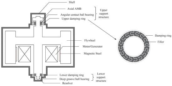
Figure 1.
Schematic of FESS structure.
(1) Flywheel rotor
The flywheel rotor is composed of shaft, hub, motor back-iron, magnet steel and carbon fiber outer ring, motor rotor, magnetic bearing rotor, etc. The carbon fiber outer rings are assembled with interference between them.
(2) Upper support structure
The upper support structure consists of an axial AMB and an upper damper from top to bottom. The axial AMB utilizes permanent magnet biased hybrid magnetic bearings. The upper damper is composed of a mechanical bearing and DR, which is used to reduce the amplitude when the rotor passes the critical speed and to enhance the system stability. The mechanical bearing comprises a pair of angular contact ball bearings.
(3) Lower support structure
The lower bearing structure is composed of a lower DR and a deep groove ball bearing.
(4) Others
The outer rotor structure is adopted in permanent magnet synchronous motors integrated with FESS. A permanent magnet motor rotor is installed on the inner wall of the flywheel rotor, which has the characteristics of high efficiency and high power density. The rotor–bearing system of the FESS is placed in a vacuum chamber, and the cooling water channel is equipped in the motor to reduce the power loss and heating of the FESS.
(5) Design principle of DR
The DR elastic support device is composed of a ring elastomer structure and a filler. Multiple -shaped spokes are evenly distributed along the circumference between the inner and outer rings of the elastomer structure. The damping values are adjusted by introducing materials such as rubber to fill the spoke gap between the inner and outer rings. The elastomer structure is utilized to primarily provide bearing support stiffness, while the rubber filler contributes a minor portion of the overall stiffness. The two stiffnesses are connected in parallel, and this design of elastic DR has both good elastic stiffness and large damping. In detail, for the adjustment of the stiffness of the DR, it is mainly adjusted by changing its own material and structure size. For example, aluminum alloy, stainless steel and other materials are chosen, and changing the material can make the stiffness change several times. In addition, the stiffness value can be changed by adjusting the spoke size between the inner and outer rings of the DR. Changing the spoke size can adjust the stiffness in a small range. In addition, when the stiffness of the DR is adjusted, the influence on the damping is small, because the main damping of the DR comes from the filling material. The damping adjustment of the DR is achieved mainly by filling different materials, such as neoprene rubber, metal rubber, plastic, wood and other materials. There are also large differences in damping between different materials. In addition, the stiffness value of these filling materials is tens of times different from that of the DR, so the stiffness of the DR will not be greatly affected when the filling material is changed.
2.2. Dynamics Modeling of FESS
According to rotordynamics, the effect of DR is evaluated by the modal damping ratio of FESS with DR. Consequently, the free vibration of FESS is analyzed in this section. The dynamic model of FESS is shown in Figure 2, and the following assumptions are made to simplify the FESS model:
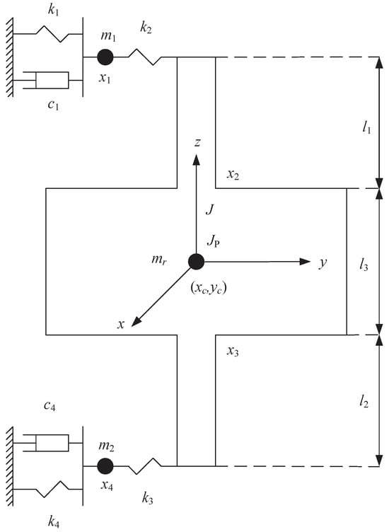
Figure 2.
Simplified model of FESS rotor–bearing system.
(1) The flywheel rotor is completely centered vertically at rest, and the effect of gravity on the shaft is not considered.
(2) The influence of the motor magnetic field on the flywheel rotor is ignored.
(3) Only the effect of radial vibration is considered, and the vibration is linear, because the radial motion of the rotor is much smaller than the axial vibration.
(4) The DR is simplified as a linear mass–spring damping system.
Based on the above assumptions, the kinetic energy T, potential energy U, and consumed energy Z of FESS are calculated, according to Lagrange’s equation.
where, , , , , , , similarly for the y-direction.
Substituting Equations (1)–(3) into Lagrange’s equation, Equation (4), of the second kind with dissipative force:
The final equation is deduced in matrix form as:
where , , , , , ,
Equation (5) is written in state-space form:
where , , .
The solution of Equation (6) is set to :
in which is the eigenvector, s is the eigenvalue, is the modal damping, is the eigenfrequency, and is the modal damping ratio. Let , then:
The mode of FESS is represented by R. Only the forward whirling mode is analyzed, since the backward whirling mode is always stable. represents the derivative of the mode. The natural frequencies and modes of the free response of the flywheel energy storage system with damping ring are solved through the above derivation.
The flywheel rotor is inevitably unbalanced. If the residual unbalance at the top and bottom of the flywheel are and , respectively, the steady state forced vibration equation of the system is obtained as [11]:
where , . The solution of the equation is:
Once the dynamic parameters of the vibration system are determined, the steady state unbalance response is calculated from Equation (11).
2.3. Method of Free Vibration Attenuation
The stiffness and damping analysis of the DR is based on the method of free vibration attenuation. And then the single degree of freedom vibration with damping is deduced. The equation of motion for a one-dimensional vibration is given [26].
where m is mass, c is damping coefficient, and k is stiffness. The form of a standard second-order equation is written as:
where is the undamped natural frequency, then:
The damping ratio and the undamped natural frequency are calculated from the waveform curves in the time domain.
The free vibration of a damped single-degree-of-freedom system can be represented by Equation (16).
This is a vibration that attenuates exponentially with an attenuation coefficient , where A is the amplitude, is damped natural frequency, is phase angle. The ratio of two adjacent amplitudes is a constant called the reduction factor .
The natural logarithm of is called the logarithmic reduction factor , where is the i-th amplitude peak, is damped natural period.
For the case of small damping, , the frequency of the decaying vibration is the damping natural angular frequency , and the damped natural period is:
3. Analysis of Dynamic Characteristics
The FESS of mechanical bearing and axial AMB hybrid support and the DR developed in our laboratory are shown in Figure 3 and Figure 4. The exterior of FESS consists of an exhaust valve, ring, vacuum shell, base, and power line. Internally, there is a flywheel rotor and motor system. The outer ring diameter of the flywheel rotor is 390 mm. And the main shaft diameter of the flywheel rotor is 42 mm. The DR consists of inner and outer rings and -shaped spokes. The inner diameter of the DR is 42 mm and the outer diameter is 72 mm. The main structural and dynamic parameters are listed in Table 1.
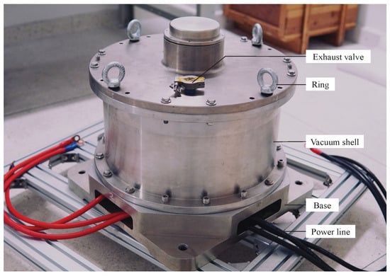
Figure 3.
FESS.
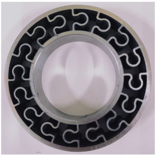
Figure 4.
Unfilled DR.

Table 1.
Structure and dynamic parameters of FESS.
3.1. Materials and Methods
The stiffness and damping coefficient of the DR will be given experimentally in the next section. A parameter measurement device for DR is illustrated in Figure 5, which mainly includes the shaft, mechanical bearing, DR, support end cap, bearing retaining ring, test mount, eddy current displacement sensor, axial tile. The experimental measurement steps of DR are shown in Figure 6, which mainly includes the preliminary work and experimental steps. In the preliminary work, the power supply should be set. The voltage is set to plus or minus 5 V, and the current is set to 0.1 A. Next, the sampling frequency of the eddy current displacement sensor is set to 5000 Hz. Then, check and ensure that the data of the 8 sampling channels are normal. Finally, the sensitivity of eddy current displacement sensor is calculated and measured several times. Next is the experimental step. Each time, the force hammer is struck on the shaft, and then the data are collected by the eddy current displacement sensor. In the course of the experiment, a number of experiments were carried out according to the rotation of the damping ring 90° each time, and a variety of hammer heads (metal hammer, plastic hammer) were replaced. The data in the experiment process can be observed in real time on the monitor, and finally, the data are processed in MATLAB-R2022a. This paper is based on the method of free vibration attenuation to perform post-processing on the measured data. And the damping and stiffness of the DR are mainly fitted through Equation (16). Finally, the results of the analysis of multiple sets of experimental data were averaged.
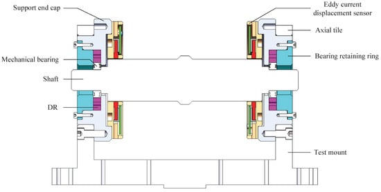
Figure 5.
Cross-section of the DR measuring device.
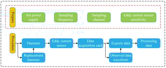
Figure 6.
Experimental procedure of DR.
3.2. Stiffness and Damping Experiment of DR
The experimental platform of DR is shown in Figure 7, which contains power supply, shielded I/O connector module, monitor, measurement device of DR, eddy current displacement sensor, computer. The experimental data of DR were fitted and calculated; the fitting curve is shown in Figure 8, and the statistical results are shown in Table 2. According to Table 2, the fitting coefficients R of the data of 6 groups are above 0.96, and the maximum SSE is 20; the fitting effect is indicated very well. The maximum and minimum values of data of each set were deleted separately and then averaged. The average damping coefficient c was 1.66 × N·s/m, the average damping ratio was 0.118, and the average stiffness k was 7.29 × N/m. The values of the experimental results of the DR are given in Table 3, and these data will be utilized for the simulation analysis later.
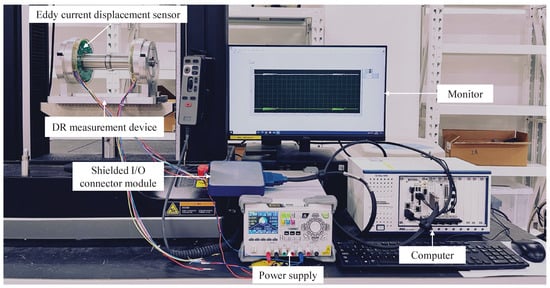
Figure 7.
Experimental platform of DR.
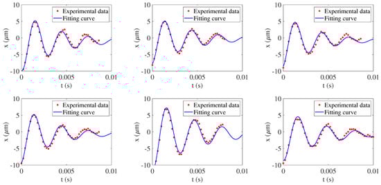
Figure 8.
Curve fitting of free decay data.
Table 2.
Experimental fitting data of rubber-filled DR.
Table 3.
The experimental results of the dynamic parameters of DR.
3.3. Dynamics of the Rotor–Bearing System
The working speed of FESS designed in this laboratory is 12,000 rpm. FESS with mechanical bearings and FESS with DR are analyzed, and the natural frequencies are shown in Table 4. Obviously, the natural frequency of FESS with DR is comparatively lower than that of mechanical bearings, and the natural frequency at 12,000 rpm is slightly higher than that at 0 rpm. The modal shapes of FESS with DR at 0 and 12,000 rpm are presented in Figure 9 and Figure 10, respectively. The first four modal shapes in the figure are rotor translational, conic, upper localized bending, and lower localized bending, respectively. The variation of the first four modes’ modal damping ratios with the damping coefficient c are shown in Figure 11. All the modal damping ratios except the third order show an increasing trend, with the increase in the damping coefficient . The fourth-order modal damping ratio is most affected by the damping coefficient . The modal damping ratios, with the exception of the fourth order, exhibit a rising trend as the damping coefficient increases. The third-order modal damping ratio is most affected by the damping coefficient . And this result also agrees with the mode shapes. The DR designed in this paper is mainly to increase the modal damping ratio of the first and second order of the system. However, the damping ratio of the third and fourth modes of the system also increases, which is also favorable. As shown in Figure 9, for the FESS, the third mode is a local mode dominated by the lower mechanical bearing vibration, and the FESS has almost no vibration. And the damping coefficient c4 increases the damping ratio of the third mode of the FESS. In other words, the damping coefficient c4 increases the damping ratio at the lower mechanical bearing. Similarly, the damping coefficient c1 increases the damping ratio at the upper mechanical bearing. This also indicates that DR has a clear effect on the damping of mechanical bearings. Since the actual motion of the FESS is the superposition of all modes, although the third and fourth modes are difficult to excite within 200 Hz, they still exist in the actual motion. In summary, the introduction of the DR can increase the modal damping ratio of the first and second order of the FESS, and help to reduce the vibration at the mechanical bearing during operation, and improve the service life of the mechanical bearing.
Table 4.
Natural frequency at different rotational speeds for FESS.
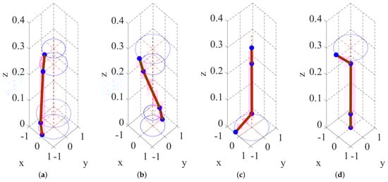
Figure 9.
Modal shapes of FESS with DR at 0 rpm: (a) first modal, (b) second modal, (c) third modal, (d) fourth modal.
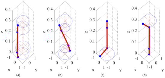
Figure 10.
Modal shapes of FESS with DR at 12,000 rpm: (a) first modal, (b) second modal, (c) third modal, (d) fourth modal.
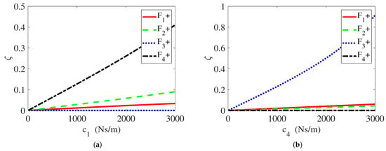
Figure 11.
Variation of 1st- to 4th-order modal damping ratio with damping coefficients: (a) , (b) .
3.4. Critical Speed
Critical speed is one of the most significant parameters of FESS. The working speed of the rigid rotor is generally required to meet , and flexible rotors are usually required to meet [27]. and are the first- and second-order critical speeds, respectively. The Campbell diagrams of the FESS with DR and mechanical bearing are shown in Figure 12. Only the forward whirling is shown, because the backward whirling is stable. The forward whirling is represented by “+”. As shown in Figure 12, the critical speed of the mechanical bearing FESS is 13,860 rpm, which is close to the working speed and does not meet the above requirements. The critical speed of FESS with DR is 5280 rpm, which meets the requirement of working speed. Therefore, the FESS with DR device can run smoothly under the working speed.
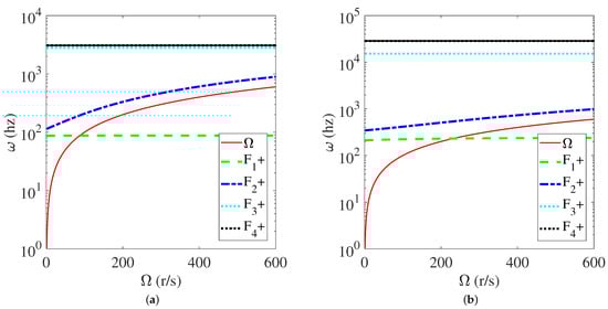
Figure 12.
Campbell diagram of the FESS: (a) REB + DR, (b) REB.
3.5. Unbalanced Response
The unbalanced response of FESS is analyzed; the unbalanced mass parameters should be given first. According to the previous unbalance measurements of the flywheel, the unbalance at the upper end face of the flywheel is about 1 × kg m, and the unbalance at the lower end face of the flywheel is about 1 × kg m. The variation of unbalance response with stiffness at the upper bearing and the upper end face of the flywheel is presented in Figure 13, where the stiffness varies in the range of 5 × ∼5 × N/m. As shown in Figure 13, the critical speed of FESS increases gradually with the increase in stiffness. The unbalanced response regularly increases first and then decreases, but the overall trend increases. Figure 14 shows the variation of the unbalance response with damping at the upper bearing and the upper end face of the flywheel, where the damping varies in the range of 1∼5000 N·s/m. As shown in Figure 14, the critical speed of the FESS rarely changes but the unbalance response decreases gradually with the increase in the damping. In addition, the overall amplitude at the upper end face of the flywheel is a bit larger than that at the upper bearing, both with the change of stiffness and damping. This demonstrates that the stiffness and damping changes have a greater effect on the amplitude at the upper end face of the flywheel.
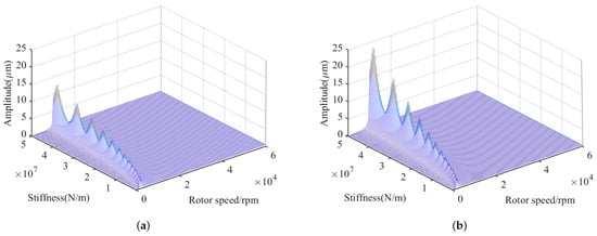
Figure 13.
Variation of unbalanced response with stiffness: (a) upper bearing, (b) upper end face of flywheel.
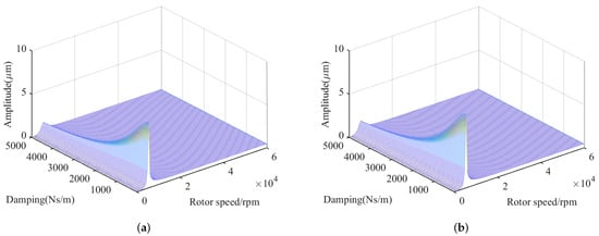
Figure 14.
Variation of unbalanced response with damping: (a) upper bearing, (b) upper end face of flywheel.
3.6. Comparison with FESS of Mechanical Bearings
In order to further illustrate the effectiveness of the DR, the unbalanced response of the mechanical bearing FESS and the FESS with DR is compared. A comparison of the unbalanced response of the bearings and the end faces of the flywheel is given in Figure 15. As shown in Figure 15, the unbalance response of the mechanical bearing has a maximum of 51.4 m and a minimum of 28.7 m. And the unbalance response of the FESS with DR is 4.2 m at maximum and 3.5 m at minimum. The unbalanced amplitude of the FESS with DR is significantly reduced; the maximum reduction is 93.11% at the lower bearing and the minimum reduction is 87.8% at the upper bearing. It can be seen that the unbalance response can be effectively suppressed by introducing the DR device into the FESS of mechanical bearings.
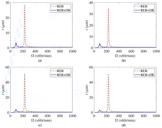
Figure 15.
Comparison of unbalanced response: (a) upper bearing, (b) upper flywheel end face, (c) lower flywheel end face, (d) lower bearing.
4. Discussion
In this paper, the problem of high friction loss and difficulty in passing the critical speed of the FESS with mechanical bearings was studied. The results indicate that the DR device designed in this paper can effectively reduce the critical speed of the FESS of mechanical bearings. And it has a good suppression effect on the unbalanced response of the FESS with mechanical bearings when passing through the critical speed. The DR device designed in this paper mainly includes the following advantages. Firstly, the DR device has a smaller volume with an outer diameter of 72 mm, which greatly reduces the space occupation compared to previous studies on tuned mass dampers [10,11], further simplifying the structure of the FESS. In addition, compared with previous studies on elastic support devices and O-rings [23,24], the stiffness of the DR can be accurately adjusted through structural materials and -shaped spokes between the inner and outer rings, and the range of stiffness adjustment has been expanded. At the same time, the damping of the DR can be adjusted by filling different materials, which can easily and quickly change the damping of the FESS. This also adds advantages to the engineering application of FESS with mechanical bearings.
Certainly, DR also has some drawbacks. Firstly, the stiffness and damping adjustment range of the DR are limited. Because the stiffness of the DR mainly depends on the material properties, the stiffness range of different materials will directly affect the stiffness adjustment of the DR. Similarly, since the damping of the DR is adjusted by filling different materials, the damping of the filling material will directly affect the damping characteristics of the DR. In addition, the DR does not have a good suppression effect on the gyroscopic effect in the FESS, which requires the use of AMB for adjustment.
The active and passive vibration control will be investigated after the dynamic analysis of the FESS with DR. In this way, the advantages of the passive control of the DR and the AMB can be combined to further improve the stability of the magnetic suspension FESS. In general, the DR device designed in this paper can reduce the friction loss of the FESS of the mechanical bearing and improve the service life of the mechanical bearing. In addition, it is very helpful to improve the working speed of the FESS of the mechanical bearing, which also lays a foundation for improving the energy storage of the FESS of the mechanical bearing in engineering application.
5. Conclusions
In this paper, the dynamic characteristics of FESS with hybrid support and DR are studied. The dynamic model of FESS of the four degree of freedom is established, and the parameters of the DR are obtained experimentally, and the natural frequency, modal shapes, critical speed, and unbalanced response of the system are calculated. The main conclusions are as follows:
(1) The damping ratio of the first- and second-order modes of FESS is effectively increased by the DR. The vibration at the mechanical bearing can be primarily mitigated when the critical speed is exceeded, the system instability caused by partial damage is avoided, and the lifetime of the mechanical bearing is increased.
(2) The critical speed of the FESS system is significantly reduced by the DR, and the FESS system can operate well under the working speed. Compared with FESS of a mechanical bearing, the critical speed is reduced from 13,860 rpm to 5280 rpm.
(3) Compared to the FESS of a mechanical bearing, the unbalanced response amplitude of the FESS with DR is reduced by more than 87.8%.
(4) The designed DR device has a simple structure and is easy to install and dismantle, and the foundation has been laid for the subsequent design of a FESS active–passive control system.
Author Contributions
Conceptualization, K.L.; Data curation, M.H.; Funding acquisition, K.L.; Investigation, M.H.; Methodology, experiment and measurement, M.H., D.L. and X.Z.; Software, M.H. and E.H.; Validation, M.H.; Writing—original draft, M.H.; Writing—review and editing, K.L., J.W. and E.H. All authors have read and agreed to the published version of the manuscript.
Funding
This work is supported by “Flywheel battery” and fuel cell pure electric vehicle hybrid power supply research and Shenzhen Basic Research (key project) (JCYJ20200109142205924).
Institutional Review Board Statement
Not applicable.
Informed Consent Statement
Not applicable.
Data Availability Statement
The data presented in this study are available on request from the corresponding author.
Acknowledgments
We would like to express our sincere gratitude to Zongyu Zhang, Jie Zhang and Jinzhao Yang for their valuable help in framing the paper. We are also grateful to Chen Hai, Mechanics Laboratory, School of Aeronautics and Astronautics, Sun Yat-sen University, for his support.
Conflicts of Interest
The authors declare no conflicts of interest.
Abbreviations
The following abbreviations are used in this manuscript:
| FESS | Flywheel energy storage system |
| PMB | Permanent magnet bearing |
| AMB | Active magnetic bearing |
| SMB | Superconducting magnetic bearing |
| REB | Rolling element bearing |
| DR | Damping ring |
| Mass of the flywheel rotor | |
| Mass of the upper damping ring after filling | |
| Mass of the lower damping ring after filling | |
| Stiffness of upper damping ring | |
| Stiffness of the upper mechanical bearing | |
| Stiffness of the lower mechanical bearing | |
| Stiffness of lower damping ring | |
| Damping coefficient of upper damping ring | |
| Damping coefficient of lower damping ring | |
| Polar moment inertia of the flywheel rotor | |
| J | Diameter moment inertia of the flywheel rotor |
| Length from upper mechanical bearing to upper end of flywheel | |
| Length from lower mechanical bearing to lower end of flywheel | |
| Length between the upper and lower ends of the flywheel | |
| Rotating speed of the rotor | |
| Modal frequency or exciting frequency | |
| x | Vibration in the direction of x-axis |
| y | Vibration in the direction of y-axis |
References
- Naderi, E.; Bibek, K.C.; Ansari, M.; Asrari, A. Experimental validation of a hybrid storage framework to cope with fluctuating power of hybrid renewable energy-based systems. IEEE Trans. Energy Convers. 2021, 36, 1991–2001. [Google Scholar] [CrossRef]
- Ershad, N.; Mehrjardi, R.; Ehsani, M. High-performance 4WD electric powertrain with flywheel kinetic energy recovery. IEEE Trans. Power Electron. 2021, 36, 772–784. [Google Scholar] [CrossRef]
- Hu, H.; Liu, K.; Wang, H.; Wei, J. A wide bandwidth GaN switching power amplifier of active magnetic bearing for a flywheel energy storage system. IEEE Trans. Power Electron. 2023, 38, 2589–2605. [Google Scholar] [CrossRef]
- Masouleh, M.; Limebeer, D. Fuel minimization for a vehicle equipped with a flywheel and battery on a three-dimensional track. IEEE Trans. Intell. Veh. 2017, 2, 161–174. [Google Scholar] [CrossRef]
- Hu, H.; Wei, J.; Wang, H.; Xiao, P.; Zeng, Y.; Liu, K. Analysis of the Notch Filter Insertion Position for Natural Frequency Vibration Suppression in a Magnetic Suspended Flywheel Energy Storage System. Actuators 2023, 12, 22. [Google Scholar] [CrossRef]
- Haidl, P.; Buchroithner, A. Design of a Low-Loss, Low-Cost Rolling Element Bearing System for a 5 kWh/100 kW Flywheel Energy Storage System. Energies 2021, 14, 7195. [Google Scholar] [CrossRef]
- Buchroithner, A.; Brandstatter, A.; Recheis, M. Mobile Flywheel Energy Storage Systems: Determining Rolling Element Bearing Loads to Expand Possibilities. IEEE Veh. Technol. Mag. 2017, 12, 83–94. [Google Scholar] [CrossRef]
- Cole, M.; Hawkins, L. Model-Based Analysis of Friction-Induced Subsynchronous Whirl for a Rotor Contacting with Clearance Bearings Under Axial Load. ASME J. Eng. Gas Turbines Power 2016, 138, 072507. [Google Scholar] [CrossRef]
- Ginzinger, L.; Ulbrich, H. Simulation-Based Controller Design for an Active Auxiliary Bearing. J. Syst. Des. Dyn. 2009, 3, 607–616. [Google Scholar] [CrossRef][Green Version]
- Qiu, Y.; Jiang, S. Suppression of low-frequency vibration for rotor-bearing system of flywheel energy storage system. Mech. Syst. Signal Process. 2019, 121, 496–508. [Google Scholar] [CrossRef]
- Qiu, Y.; Jiang, S. Dynamics of Flywheel Energy Storage System with Permanent Magnetic Bearing and Spiral Groove Bearing. J. Dyn. Syst. Meas. Control 2018, 140, 021006. [Google Scholar] [CrossRef]
- Xiang, B.; Liu, H. Dynamic Vibration Absorbing Performance of 5-DoF Magnetically Suspended Momentum Wheel Based on Damping Regulation. Actuators 2023, 12, 152. [Google Scholar] [CrossRef]
- Hopf, T.; Richter, M.; Schüßler, B.; Rinderknecht, S. Control Strategies for Highly Gyroscopic Outer Rotors with Diametral Enlargement in Active Magnetic Bearings. Actuators 2022, 11, 91. [Google Scholar] [CrossRef]
- Lee, H.; Jung, S.; Cho, Y. Peak Power Reduction and Energy Efficiency Improvement with the Superconducting Flywheel Energy Storage in Electric Railway System. Phys. C Supercond. 2013, 494, 246–249. [Google Scholar] [CrossRef]
- Komori, M.; Kato, H.; Asami, K.-I. Suspension-Type of Flywheel Energy Storage System Using High Tc Superconducting Magnetic Bearing (SMB). Actuators 2022, 11, 215. [Google Scholar] [CrossRef]
- Breńkacz, Ł.; Witanowski, Ł.; Drosińska-Komor, M.; Szewczuk-Krypa, N. Research and applications of active bearings: A state-of-the-art review. Mech. Syst. Signal Process. 2021, 151, 107423. [Google Scholar] [CrossRef]
- Fang, J.; Tang, E.; Zheng, S. Optimum Damping Control of the Flexible Rotor in High Energy Density Magnetically Suspended Motor. ASME J. Eng. Gas Turbines Power 2015, 137, 082505. [Google Scholar] [CrossRef]
- Sato, D.; Itoh, J.; Watanabe, T.; Kawagoe, K.; Yamada, N.; Kato, K. 2015 Development of magnetic coupling with variable thrust structure for flywheel energy storage system in long lifetime UPS. In Proceedings of the IEEE International Telecommunications Energy Conference (INTELEC), Osaka, Japan, 18–22 October 2015. [Google Scholar]
- Yang, D.; Qin, H.; Xie, X.; Zhang, Z. Suppression of lateral vibration in a shafting system via an auxiliary active magnetic bearing with position control. Proc. Inst. Mech. Eng. C J. Mech. Eng. Sci. 2023, 237, 1581–1594. [Google Scholar] [CrossRef]
- Recheis, M.; Buchroithner, A.; Andrasec, I.; Gallien, T.; Schweighofer, B.; Bader, M.; Wegleiter, H. Improving kinetic energy storage for vehicles through the combination of rolling element and active magnetic bearings. In Proceedings of the IECON 2013-39th Annual Conference of the IEEE Industrial Electronics Society, Vienna, Austria, 10–13 November 2013. [Google Scholar]
- Xu, K.; Guo, Y.; Lei, G.; Zhu, J. A Review of Flywheel Energy Storage System Technologies. Energies 2023, 16, 6462. [Google Scholar] [CrossRef]
- Kang, X.; Palazzolo, A. Simulation, Test, and Mitigation of ½× Forward Whirl Following Rotor Drop Onto Auxiliary Bearings. ASME J. Eng. Gas Turbines Power 2020, 142, 041020. [Google Scholar] [CrossRef]
- Haidl, P.; Zisser, M.; Buchroithner, A.; Schweighofer, B.; Wegleiter, H.; Bader, M. Improved Test Rig Design for Vibration Control of a Rotor Bearing System. In Proceedings of the 23rd International Congress on Sound and Vibration, Athens, Greece, 10–14 July 2016. [Google Scholar]
- Buchroithner, A.; Haan, A.; Preßmair, R.; Bader, M.; Schweighofer, B.; Wegleiter, H.; Edtmayer, H. Decentralized low-cost flywheel energy storage for photovoltaic systems. In Proceedings of the 2016 International Conference on Sustainable Energy Engineering and Application (ICSEEA), Jakarta, Indonesia, 3–5 October 2016. [Google Scholar]
- Jiang, S.; Wang, H.; Wen, S. Flywheel Energy Storage System with a Permanent Magnet Bearing and a Pair of Hybrid Ceramic Ball Bearings. J. Mech. Sci. Technol. 2014, 28, 5043–5053. [Google Scholar] [CrossRef]
- Wang, J. Vibration Measurement and Analysis of Energy Storage Flywheel System. Master’s Thesis, Tsinghua University, Beijing, China, 2008; pp. 18–19. [Google Scholar]
- Cheng, D. Mechanical Design Manual, 6th ed.; Chemical Industry Press: Beijing, China, 2017; Volume 2, p. 31. [Google Scholar]


Disclaimer/Publisher’s Note: The statements, opinions and data contained in all publications are solely those of the individual author(s) and contributor(s) and not of MDPI and/or the editor(s). MDPI and/or the editor(s) disclaim responsibility for any injury to people or property resulting from any ideas, methods, instructions or products referred to in the content. |
© 2024 by the authors. Licensee MDPI, Basel, Switzerland. This article is an open access article distributed under the terms and conditions of the Creative Commons Attribution (CC BY) license (https://creativecommons.org/licenses/by/4.0/).